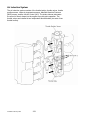
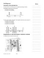
1
Outboard FourStroke II Technician’s Guide 1 Table of Contents Section 1 – General Information Section 2 – Product Updates Section 3 – EFI System Components/Operation Section 4 – Diagnostics Section 5 – Service Bulletins Section 6 – Tool Suppliers 3 2 Notes:_________________________________________________ _______________________________________________________ _______________________________________________________ _______________________________________________________ _______________________________________________________ _______________________________________________________ _______________________________________________________ _______________________________________________________ _______________________________________________________ _______________________________________________________ _______________________________________________________ _______________________________________________________ _______________________________________________________ _______________________________________________________ _______________________________________________________ _______________________________________________________ _______________________________________________________ _______________________________________________________ _______________________________________________________ _______________________________________________________ _______________________________________________________ _______________________________________________________ _______________________________________________________ _______________________________________________________ _______________________________________________________ _______________________________________________________ _______________________________________________________ _______________________________________________________ _______________________________________________________ _______________________________________________________ _______________________________________________________ _______________________________________________________ _______________________________________________________ _______________________________________________________ _______________________________________________________ 4 3 Section 1 - General Information 90-898313 1-1 4 Table of Contents Table of Contents.............................................................................................2 Table of Contents.............................................................................................3 Exhaust Emissions Standards ..........................................................................4 What Are Emissions? .................................................................................... 4 Hydrocarbons - HC........................................................................................ 4 Carbon Monoxide - CO ................................................................................. 4 Oxides of Nitrogen - Nox ............................................................................... 4 Stoichiometric (14.7:1) Air/Fuel Ratio............................................................ 5 Engine Emission Certification Label .................................................................6 Propeller Selection............................................................................................7 Prop Rattle and Flo-Torq III Propeller Hub........................................................8 Prop Rattle .................................................................................................... 8 FLO-TORQ III PROP HUB ............................................................................ 8 Propellors for Pontoon................................................................................. 10 Special Aluminum Propellers Required for 40/50/60 Bigfoot 4-Stroke Models .................................................................................................................... 10 Mercury/Mariner 40/50 Bigfoot 4–Stroke 2.31:1.......................................... 11 Mercury/Mariner 60 Bigfoot 4–Stroke 2.31:1............................................... 11 Battery.............................................................................................................12 Precautions ................................................................................................. 12 Battery Specification.................................................................................... 13 Battery Rating System................................................................................. 13 Cold Cranking Amps (CCA) ........................................................................ 13 Marine Cranking Amps (MCA)..................................................................... 13 Reserve Capacity ........................................................................................ 13 Amperage/Hour Rating................................................................................ 14 Charging Guide ........................................................................................... 14 Effects of Temperature on a Standing Battery ............................................ 14 Battery Cable Wire Gauge Size................................................................... 16 Fuel-Alcohol and Contaminants .................................................................. 17 Alcohol in Fuel Testing Procedure .............................................................. 17 Contaminants in Fuel Testing Procedure .................................................... 17 Effects of Fuel on Carbureted Models ......................................................... 18 Effects of Fuel on EFI Models ..................................................................... 18 Oil Dilution ................................................................................................... 18 90-898313 1-3 5 Notes ______________ ______________ ______________ ______________ ______________ ______________ ______________ ______________ ______________ ______________ ______________ ______________ ______________ ______________ ______________ ______________ ______________ ______________ ______________ ______________ ______________ ______________ ______________ ______________ ______________ ______________ ______________ ______________ ______________ ______________ ______________ ______________ ______________ ______________ ______________ ______________ ______________ ______________ ______________ ______________ Exhaust Emissions Standards Through the Environmental Protection Agency (EPA), the federal government has established exhaust emissions standards for all new marine engines sold in the U.S. What Are Emissions? Emissions are what comes out of the exhaust system in the exhaust gas when the engine is running. They are formed as a result of the process of combustion or incomplete combustion. To understand exhaust gas emissions, remember that both air and fuel are made of several elements. Air contains oxygen and nitrogen among other elements; gasoline contains mainly hydrogen and carbon. These four elements combine chemically during combustion. If combustion were complete, the mixture of air and gasoline would result in these emissions: water, carbon dioxide and nitrogen, which are not harmful to the environment. But combustion is not usually complete. Also, potentially harmful gases can be formed during and after combustion. All marine engines must reduce the emission of certain pollutants, or potentially harmful gases, in the exhaust to conform with levels legislated by the EPA. Emissions standards become more stringent each year. Standards are set primarily with regard to three emissions: hydrocarbons (HC), carbon monoxide (CO) and oxides of nitrogen (NOx). Hydrocarbons - HC Gasoline is a hydrocarbon fuel. The two elements of hydrogen and carbon are burned during combustion in combination with oxygen. But they are not totally consumed. Some pass through the combustion chamber and exit the exhaust system as unburned gases known as hydrocarbons. Carbon Monoxide - CO Carbon is one of the elements that make up the fuel burned in the engine along with oxygen during the combustion process. If the carbon in the gasoline could combine with enough oxygen (one carbon atom with two oxygen atoms), it would come out of the engine in the form of carbon dioxide (CO2). CO2 is a harmless gas. But carbon often combines with insufficient oxygen (one carbon atom with one oxygen atom). This forms carbon monoxide, CO. Carbon monoxide is the product of incomplete combustion and is a dangerous, potentially lethal gas. Oxides of Nitrogen - Nox NOx is a slightly different byproduct of combustion. Nitrogen is one of the elements that makes up the air going into the engine. Under extremely high temperatures it combines with oxygen to form oxides of nitrogen (NOx). This happens in the engine’s combustion chambers when temperatures are too high. NOx itself is not harmful, but when exposed to sunlight it combines with unburned hydrocarbons to create the visible air pollutant known as smog. Smog is a serious problem in California as well as many other heavily populated areas of the United States. 90-898313 1-4 6 Stoichiometric (14.7:1) Air/Fuel Ratio In the search to control pollutants and reduce exhaust emissions, engineers have discovered that they can be reduced effectively if a gasoline engine operates at an air/fuel ratio of 14.7:1. The technical term for this ideal ratio is stoichiometric. An air/fuel ratio of 14.7:1 provides the best control of all three elements in the exhaust under almost all conditions. The HC and CO content of the exhaust gas is influenced significantly by the air/fuel ratio. At an air/fuel ratio leaner than 14.7:1, HC and CO levels are low, but with a ratio richer than 14.7:1 they rise rapidly. It would seem that controlling HC and CO by themselves might not be such a difficult task; the air/fuel ratio only needs to be kept leaner than 14.7:1. However, there is also NOx to consider. As the air/fuel ratio becomes leaner, combustion temperatures increase. Higher combustion temperatures raise the NOx content of the exhaust. But, enrichening the air/fuel ratio to decrease combustion temperatures and reduce NOx also increases HC and CO, as well as lowering fuel economy. So the solution to controlling NOx - as well as HC and CO - is to keep the air/fuel ratio as close to 14.7:1 as possible. 90-898313 1-5 7 Notes ______________ ______________ ______________ ______________ ______________ ______________ ______________ ______________ ______________ ______________ ______________ ______________ ______________ ______________ ______________ ______________ ______________ ______________ ______________ ______________ ______________ ______________ ______________ ______________ ______________ ______________ ______________ ______________ ______________ ______________ ______________ ______________ ______________ ______________ ______________ ______________ ______________ ______________ ______________ ______________ Engine Emission Certification Label Your outboard has been labeled on the cowl with one of the following star labels. The Symbol for Cleaner Marine Engines Means: Cleaner Air and Water – for a healthier lifestyle and environment. Better Fuel Economy – burns up to 30-40 percent less gas and oil than conventional carbureted two-stroke engines, saving money and resources. Longer Emission Warranty – Protects consumer for worry free operation. The one-star label identifies engines that meet the CARB's 2001 exhaust emission standards. Engines meeting these standards have 75% lower emissions than conventional carbureted 2-stroke engines. These engines are equivalent to the U.S. EPA's 2006 standards The two-star label identifies engines that meet the CARB's 2004 exhaust emission standards. Engines meeting these standards have 20% lower emissions than One Star Low Emission engines. The three-star label identifies engines that meet the CARB's 2008 exhaust emission standards. Engines meeting these standards have 65% lower emissions than One Star - Low Emission engines. The four Star label identifies engines that meet the Air Resources Board's Sterndrive and Inboard marine engine 2009 exhaust emission standards. Personal Watercraft and Outboard marine engines may also comply with these standards. Engines meeting these standards have 90% lower emissions than One Star - Low Emission engines. 90-898313 1-6 8 Propeller Selection For best all around performance from your outboard/boat combination, select a propeller that allows the engine to operate at or neat the top of the recommended full throttle RPM range with the boat normally loaded (refer to Specifications). This RPM range allows for better acceleration while maintaining maximum boat speed. If changing conditions cause the RPM to drop below the recommended range (such as warmer, more humid weather, operation at higher elevations, increased boat load or a dirty boat bottom/gear case) a propeller change or cleaning may be required to maintain performance and ensure the outboard’s durability. Diagnostic Tip: Over propping can cause a FourStroke to stall when shifting into gear. These symptoms can result in misdiagnosis of the fuel system. When the engine that is overloaded with too large a prop may allow excess fuel to bypass the piston rings and dilute the crank case oil. The long term effects would be premature powerhead failure. Under propping can cause overrev condition. The long term effects could lead to oil coming out of the breather. As a general rule for every 1 inch of pitch change, the effect will be approximately 200 RPM. Check full-throttle RPM using an accurate tachometer with the engine trimmed out to a balanced-steering condition (steering effort equal in both directions) without causing the propeller to “break loose”. Refer to “Quicksilver Accessory Guide” for a complete list of available propellers. 1) Select a propeller that will allow the engine to operate at or near the top of the recommended full throttle RPM range (listed in “Specifications,” preceding) with a normal load. Maximum engine speed (RPM) for propeller selection exists when boat speed is maximum and trim is minimum for that speed. (High RPM, caused by an excessive trim angle, should not be used in determining correct propeller.) Normally, there is a 150-350RPM change between propeller pitches. 2) If full throttle operation is below the recommended range, the propeller MUST BE changed to one with a lower pitch to prevent loss of performance and possible engine damage. 3) After initial propeller installation, the following common conditions may require that the propeller be changed to a lower pitch: a) Warmer weather and great humidity will cause an RPM loss. b) Operating in a higher elevation causes an RPM loss. c) Operating with a damaged propeller or a dirty boat bottom or gear housing will cause an RPM loss. d) Operation with an increased load (additional passengers, equipment, pulling skiers, etc.). Tip: All 4-Stroke engines should be propped to the top of recommended RPM range for best overall performance and customer satisfaction. 90-898313 1-7 9 Notes _______________________ _______________________ _______________________ _______________________ _______________________ _______________________ _______________________ _______________________ _______________________ _______________________ _______________________ _______________________ _______________________ Prop Rattle and Flo-Torq III Propeller Hub Prop Rattle Crankshaft and driveshaft speed varies during rotation due to power strokes. This is the result of the piston coming up on its power stroke and combustion occurring, which in turn causes the crankshaft and prop shaft speed to increase. In between power strokes the crankshaft speed slows down due to normal drag in the system, while inertia of the prop causes the propeller shaft to remain rotating close to the same speed. Prop rattle is seen more often in engines that use stainless steel props. The increased weight, and the resulting increased inertial force generated by these stainless steel props allow the props to maintain more of a constant speed, as compared with that of the crankshaft’s speed. Consequently, the stainless steel prop does not slow down at the same rate as the crankshaft, and accordingly the clutch dogs separate slightly between the clutch and the gear. On the next power stroke, the crankshaft will again accelerate and create a slight noise when the clutch dogs on the drive gear catch up with the dogs on the clutch/prop shaft. When this is repeated over and over it results in prop rattle. IMPORTANT: This prop rattle does not damage the clutch dogs or lower unit, and is normally only heard at idle or just off idle speeds. _______________________ _______________________ FLO-TORQ III PROP HUB _______________________ The Flo-Torq III plastic drive sleeve assembly has a small forward/aft clearance so that it or the prop is not locked to the prop shaft. This allows the two hub pieces to rotate ± 10° relative to each other, and allows the springs to absorb the impacts from the combustion cycles instead of the clutch dogs. The plastic drive sleeve assembly has clearance, which allows it to move forward and aft slightly over the inner brass hub that is supplied with the Flo-Torq III hub kit. This free movement, along with the spring wires between the forward and aft section of the plastic hub, act as a shock absorber, reducing the noise. Do not shorten the inner brass hub of a Flo-Torq III prop hub; the prop must be allowed to have a slight forward and aft clearance. Aluminum props do not have the weight and mass (inertia) to remain at a constant speed. Generally aluminum props tend to remain at crankshaft speed. Because of this, the clutch dogs do not separate and there is very little or no prop rattle. _______________________ _______________________ _______________________ _______________________ _______________________ _______________________ _______________________ _______________________ _______________________ _______________________ _______________________ _______________________ 90-898313 1-8 10 Diagnostic Tip: Customer complaining of low pitch whine from gearcase at 1200-2400 RPM. Models: 1997 and newer 25-60hp fourstrokes usually on pontoon applications using 8, 9, or 10.5 inch pitch propellers. Possible cause: is propeller vibration which will not effect the gearcase durability. Correction: install propeller that has trailing edge tapered in the form of chisel point. 90-898313 1-9 11 Propellors for Pontoon Style Part Number Mercury 9.9 - 15 HP Black 48Max 850204A12 Diameter Pitch & # Blades Material 4 Aluminum Large blade area used on Pro Kicker 3 Aluminum Large blade area with cup 3 Aluminum Large blade area with extra cup 3 Aluminum Large blade area with cup 3 Aluminum Large blade area with cup 3 Aluminum Large blade area with cup 14" x 9" 3 Aluminum 14" x 10" 3 Aluminum 14" x 11" 3 Aluminum 9 3/4" x 6 Mercury 9.9 - 15 HP BigFoot, 20 - 25 HP Black Max 48-19636A10 10 3/8" x 9 1/2" Mercury 25 HP BigFoot, 30-40 & 50-60 HP Black Max 48-42738A13 12 1/2" x 8" Black Max 48-42738A11 12 1/2" x 8" Black Max 48-87818A11 12 1/4" x 9" Black Max 48-42740A11 12" x 10 1/2" Mercury 40 - 60 HP BigFoot Black 48Max 854340A33 Black 48Max 854342A33 Black Max 48-77338A33 Feature Large blade area with special rubber hub Large blade area with special rubber hub Large blade area with special rubber hub Special Aluminum Propellers Required for 40/50/60 Bigfoot 4-Stroke Models MERCURY/MARINER 2000 40/50/60 Bigfoot 4–Stroke USA 0G960500 and Above Outboards listed, require the use of specially designed rubber hub aluminum propellers to reduce both the instances and severity of gear case clutch rattle. The use of other propellers, (including stainless steel propellers) although not detrimental to either performance or durability could result in clutch rattle. IMPORTANT: These specially designed rubber hub aluminum propellers are now rated for 60 horsepower MAXIMUM. This new 60 rating applies to and supercedes the previous 50 rating listed for these propellers. 90-898313 1-10 12 Mercury/Mariner 40/50 Bigfoot 4–Stroke 2.31:1 Wide Open Throttle RPM : 5500-6000 Recommended Transom Heights : 20”, 25” Right Hand Rotation Standard Gear Reduction : 2.31:1 Diameter Pitch No. of Blades Material Approx. Boat Length Speed Range (mph) Propeller Part Number Alum. Approx. Gross Boat Weight (lbs) 1500-2000 13-3/4” 15” 3 14-16’ 25-32 48-77342A33 14” 13” 3 Alum. 1800-2600 16-18’ 23-27 48-77340A33 14” 11” 3 Alum. 2800-4000 Pontoon 17-21 48-77338A33 14” 10” 3 Alum. 3000+ Pontoon/work 14-19 48-854342A33 14” 9” 3 Alum. 5000+ Houseboat/work 1-16 48-854340A33 Speed Range (mph) Propeller Part Number Mercury/Mariner 60 Bigfoot 4–Stroke 2.31:1 Wide Open Throttle RPM : 5500-6000 Recommended Transom Heights : 20”, 25” Right Hand Rotation Standard Gear Reduction : 2.31:1 Diameter Pitch No. of Blades Material 13-3/4” 15” 3 14” 13” Approx. Boat Length Alum. Approx. Gross Boat Weight (lbs) 2000-2500 16-18’ 25-32 48-77342A33 3 Alum. 2300-3200 17-20’ 23-27 48-77340A33 14” 11” 3 Alum. 3000-4300 Pontoon 17-21 48-77338A33 14” 10” 3 Alum. 3500+ Pontoon/work 14-19 48-854342A33 14” 9” 3 Alum. 5500+ Houseboat/work 1-16 48-854340A33 When using Mercury stainless steel propellers 40-60 HP Bigfoot and 75-115 4stroke engines, use Flo-Torq III hub kit P/N 835257K9. This hub kit is specially designed to reduce gearcase operating sound and to increase customer satisfaction. 90-898313 1-11 13 Notes _______________________ Battery _______________________ Precautions _______________________ When charging batteries, an explosive gas mixture forms in each cell. A portion of this gas escapes thru holes in vent plugs and may form an explosive atmosphere around battery if ventilation is poor. This explosive gas may remain in or around battery for several hours after it has been charged. Sparks or flames can ignite this gas and cause an internal explosion which may shatter the battery. _______________________ _______________________ _______________________ _______________________ _______________________ _______________________ _______________________ _______________________ _______________________ The following precautions should be observed to prevent an explosion. 1) DO NOT smoke near batteries being charged or which have been charged very recently. 2) DO NOT break live circuits at terminals of batteries because a spark usually occurs at the point where a live circuit is broken. Always be careful when connecting or disconnecting cable clamps on chargers. Poor connections are a common cause of electrical arcs which cause explosions. 3) DO NOT reverse polarity of battery cables on battery terminals. 4) Wear eye protection. _______________________ _______________________ _______________________ CAUTION If battery acid comes into contact with skin or eyes, wash skin immediately with a mild soap. Flush eyes with water immediately and see a doctor. _______________________ _______________________ _______________________ _______________________ _______________________ _______________________ _______________________ _______________________ _______________________ _______________________ _______________________ _______________________ _______________________ 90-898313 1-12 14 Battery Specification Model Cold Cranking Amps (CCA) Marine Cranking Amps (MCA) 350 465 350 Above 32° F (0°C) 465 Above 32° F (0°C) 775 Below 32° F (0°C) 1000 Below 32° F (0°C) 4-Stroke 8.0 – 25 30-90/115/225 Carb & EFI Models NOTE: Battery specifications listed are minimum requirements for the outboard motor only, boats with additional electrical accessories will require larger batteries than listed. Battery Rating System There are two major rating systems used in the USA for marine engine cranking batteries. The most common is CCA (cold cranking amps) which rates the cranking amps at 0° F. The second system, mca (marine cranking amps), rates the cranking amps at 32° F. The mca rating of a given battery is always higher than the cca rating. Cold Cranking Amps (CCA) This figure represents in amps the current flow the battery can deliver for 30 seconds at 0º Fahrenheit without dropping below 1.2 volts per cell (7.2 volts on a standard 12 volt battery). The higher the number, the more amps it can deliver to crank the engine. (CCA x 1.3 = MCA). Marine Cranking Amps (MCA) This figure is similar to the CCA test figure except that the test is run at 32º Fahrenheit instead of ”0”. (MCA x.77 = CCA). This is more in line with actual boat operating conditions. Reserve Capacity This figure represents the time in minutes that a fully charged battery at 80º Fahrenheit can deliver 25 amps, without dropping below 1.75 volts per cell (10.5 volts on a standard 12 volt battery). The reserve capacity rating defines the length of time that a typical vehicle can be driven after the charging system fails. The 25 amp figure takes into account the power required by the ignition, lighting and other accessories. The higher the reserve capacity rating, the longer the vehicle could be driven after a charging system failure. 90-898313 1-13 15 Notes Amperage/Hour Rating _______________________ The ampere hour rating method is also called the 20 hour rating method. This rating represents the steady current flow that the battery will deliver for 20 hours while at 80º Fahrenheit without dropping below 1.75 volts per cell (10.5 volts on a standard 12 volt battery). The rating is actually the steady current flow times the 20 hours. _______________________ Example: A 60 amp–hour battery will deliver 3 amps continuously for 20 hours. _______________________ _______________________ _______________________ _______________________ _______________________ Charging Guide 12 Volt Battery Recommended Rate* and Time for Fully Discharged Condition _______________________ _______________________ _______________________ _______________________ _______________________ _______________________ _______________________ _______________________ _______________________ _______________________ _______________________ _______________________ _______________________ _______________________ _______________________ _______________________ _______________________ _______________________ _______________________ _______________________ _______________________ * Initial rate for constant voltage taper rate charger To avoid damage, charging rate must be reduced or temporarily halted, if: 1. Electrolyte temperature exceeds 125° F (52° C). 2. Violent gassing or spewing of electrolyte occurs. Battery is fully charged when, over a two hour period at a low charging rate in amperes, all cells are gassing freely and no change in specific gravity occurs. For the most satisfactory charging, the lower charging rates in amperes are recommended. Full charge specific gravity is 1.260-1.280, corrected for temperature with electrolyte level at split ring. Effects of Temperature on a Standing Battery The parasitic drain will be fairly constant over a range of temperatures. The important temperature is that of the boat at the time a start is attempted. Colder temperature raises the threshold of a no-start by increasing the residual power needed. When the temperature falls to 0°C (32°F), the battery will be able to put out only about 85% of its normally available starting power, and the engine may need as much as 165% of the usual power to start. The combined effect of these two factors is to reduce the number of days the battery can stand with a parasitic drain. At 0°C (32°F), the battery can stand only half as long as it could at 25°C (77°F). And at -19°C (0°F), the standing days are reduced to one-fourth. 90-898313 1-14 16 Temperatures above the moderate climate of 25°C (77°F) increase the battery's internal self discharge. If the battery is in a location where the temperature is averaging 32°C (90°F), an additional 5% to 10% of the available ampere-hours will be lost in a month due to self-discharge within the battery. At temperatures below the moderate range, self-discharge will be low enough to be insignificant compared to the parasitic loss. Discharged batteries can freeze at temperatures as high as 0°C (32°F), causing permanent damage. Other permanent damage may result from allowing batteries to stand discharged for extended periods. IMPORTANT: The battery specification listed below is generic specification. Notes _______________________ _______________________ _______________________ _______________________ _______________________ _______________________ The battery run down time will vary depending on cold cranking amperage (CCA) and reserve capacity (RC). If the CCA and RC are higher, then the battery run down time would be longer. If the CCA and RC are lower, then the battery run down time would be shorter. The graph below indicates roughly how many days a 690 CCA battery with at 110 min. RC (60.5 AH) starting at 80 percent state of charge will last with a constant current draw until it reaches 50 percent state of charge. Differences in battery rating and temperature will affect the results. _______________________ _______________________ _______________________ _______________________ _______________________ _______________________ Current Drain Days _______________________ 25 mA 30.5 _______________________ 50 mA 16.5 75 mA 11 100 mA 8.25 _______________________ 250 mA 3.3 _______________________ 500 mA 1.65 750 mA 1 1A 0.8 _______________________ 2A 0.4 _______________________ _______________________ _______________________ _______________________ _______________________ _______________________ _______________________ _______________________ _______________________ _______________________ _______________________ 90-898313 1-15 17 Battery Cable Wire Gauge Size Only use copper battery cables. See chart below for correct wire gage size. 1. Standard (original) cable length and wire gauge size. 90-898313 1-16 18 Fuel-Alcohol and Contaminants Notes Water contamination in the fuel system may cause driveability conditions such as hesitation, stalling, no start, or misfires in one or more cylinders. Water may collect near a single fuel injector at the lowest point in the fuel rail, and cause a misfire in that cylinder. If the fuel system is contaminated with water, inspect the fuel system components for rust, or deterioration. _______________________ Alcohol concentrations of 10 percent or greater in fuel can be detrimental to fuel system components. Alcohol contamination may cause fuel system corrosion, deterioration of rubber components, and subsequent fuel filter restriction. Fuel contaminated with alcohol may cause driveability conditions such as hesitation, lack of power, stalling, or no start. Some types of alcohol are more detrimental to fuel system components than others. _______________________ Alcohol in Fuel Testing Procedure The fuel sample should be drawn from the bottom of the tank so that any water present in the tank will be detected. The sample should be bright and clear. If alcohol contamination is suspected then use the following procedure to test the fuel quality. 1. Using a 3.4 oz (100 ml) specified cylinder with 0.03 oz (1 ml) graduation marks, fill the cylinder with fuel to the 3.0 oz (90 ml) mark. 2. Add 0.34 oz (10 ml) of water in order to bring the total fluid volume to 100 ml and install a stopper. 3. Shake the cylinder vigorously for 10-15 seconds. 4. Carefully loosen the stopper in order to release the pressure. 5. Install the stopper and shake the cylinder vigorously again for 10 to 15 seconds. _______________________ _______________________ _______________________ _______________________ _______________________ _______________________ _______________________ _______________________ _______________________ _______________________ _______________________ _______________________ _______________________ _______________________ 6. Put the cylinder on a level surface for approximately 5 minutes in order to allow adequate liquid separation. If alcohol is present in the fuel, the volume of the lower layer, which would now contain both alcohol and water, will be more than 0.34 oz (10 ml). For example, if the volume of the lower layer is increased to 0.51 oz (15 ml), this indicates at least 5 percent alcohol in the fuel. The actual amount of alcohol may be somewhat more because this procedure does not extract all of the alcohol from the fuel. Contaminants in Fuel Testing Procedure _______________________ _______________________ _______________________ _______________________ _______________________ _______________________ The fuel sample should be drawn from the bottom of the tank so that any water present in the tank will be detected. The sample should be bright and clear. If the sample appears cloudy, or contaminated with water, as indicated by a water layer at the bottom of the sample, use the following procedure to diagnose the fuel. _______________________ 1. Using an approved fuel container, draw approximately 0.5 quart _______________________ (0.5 liter) of fuel. 2. Place the cylinder on a level surface for approximately 5 minutes in order to allow settling of the particulate contamination. 90-898313 _______________________ _______________________ _______________________ _______________________ 1-17 19 Notes _______________________ _______________________ _______________________ _______________________ _______________________ Particulate contamination will show up in various shapes and colors. Sand will typically be identified by a white or light brown crystals. Rubber will appear as black and irregular particles. If particles are found clean the entire fuel system thoroughly. Effects of Fuel on Carbureted Models Carburetors on FourStrokes engines are made with great precision (small passages) to deliver the exact amount of fuel in order to complete very clean combustion process. Improper storage (causing varnishing) and contaminated fuel can result in plugging these passages. _______________________ Effects of Fuel on EFI Models _______________________ EFI models are not exempt from improper storage and fuel contaimination. The Vapor Separator Tank (VST) is vented just as a carburator bowl. If fuel remains in the VST untreated durning storage it will varnish. Only in this case the electric fuel pump could be damaged from the varnish adhering to the commutator and brushes. The injectors also have filters in their inlets that can restrict the flow of fuel resulting in lack of power, misfire complaint or flat spot. The injector might be able to flow the fuel at low RPM but not as fuel demand increases. _______________________ _______________________ _______________________ _______________________ _______________________ . Educating the customer of the importance of proper winterization and filter maintance can help in eliminating these issues. Remind your customers about the proper use of fuel stabilizers. Reference the Owners Manual for specific procedures. Do not treat the symptom without addressing the cause or a repeat failure will occur. _______________________ Oil Dilution _______________________ All FourStroke outboards will have some degree of oil dilution. Normally, the oil level fluctuates a small degree without notice. In some cases the dilution rate exceceds the normal amount and causes an issue when the oil pan completely fills and restricts crankcase ventilation. _______________________ _______________________ _______________________ _______________________ _______________________ _______________________ _______________________ _______________________ _______________________ There are serveral possible causes to keep in mind when diagnosing an excessive oil dilution complaint. Engine temperature is very critical to obtain proper piston ring sealing. Verify proper heat range of spark plugs and engine operating temperature. Excessive fuel in the combustion chamber and overpropping could also contribute. Most often the problem is caused by improper breakin procedure during the first hours of engine run operation. During this phase the rings are seating into their final position in the ring land of the piston. If the engine is run at a very low RPM for long durations the rings may never seat. _______________________ _______________________ _______________________ _______________________ _______________________ 90-898313 1-18 20 Section 2 Product Updates 90-898313 2-1 21 Table of Contents Table of Contents ............................................................................................. 2 Product Changes - 2004 MY ............................................................................ 3 4/5/6 .............................................................................................................. 3 9.9/15 ............................................................................................................ 3 25 .................................................................................................................. 3 Recoil Starter Housing - 25 thru 40............................................................... 4 30/40 ............................................................................................................. 5 Electric Fuel Pump - 30 thru 60 EFI .............................................................. 5 Stator - 30/40 EFI & 40/50/60 EFI................................................................. 6 40BF/50/60.................................................................................................... 7 Speedometer Tube - Removed..................................................................... 7 75/90/115 ...................................................................................................... 8 Carburetor Calibration - 90............................................................................ 8 Cowl Latch Handle ........................................................................................ 9 Water Tube (Copper-Nickel) ......................................................................... 9 Desmodromic (EZ Shift) Gearcase ............................................................. 10 Adapter Plate (EZ Shift) .............................................................................. 10 Shift Link Bracket (EZ Shift) ........................................................................ 10 Barrel Cup Retainer (EZ Shift) .................................................................... 11 Control Cable Latch (EZ Shift) .................................................................... 11 Reverse Gear (EZ Shift).............................................................................. 11 Shift Shaft Bushing (EZ Shift) ..................................................................... 12 Upper Shift Shaft Assembly (EZ Shift) ........................................................ 12 Shift Detent Assembly (EZ Shift)................................................................. 12 Shift Cam (EZ Shift) .................................................................................... 12 Cam Follower (EZ Shift).............................................................................. 13 Tiller Handle Kit – 75/90 &115 EFI (4-Stroke)............................................. 13 225 .............................................................................................................. 14 Product and Running Model Year Changes 2005-2006 ................................. 15 4/5/6 ............................................................................................................ 15 9.9/15 .......................................................................................................... 18 8-9.9 TMC/Mercury Joint Venture .............................................................. 18 30/40 3 Cylinder EFI & 40/50/60 4 Cylinder EFI ........................................ 20 WATER TUBE (COOPER-NICKEL) ........................................................... 22 84-858740T_............................................................................................... 27 84-898142T_............................................................................................... 28 90-898313 2-2 22 Product Changes - 2004 MY Notes _______________________ 4/5/6 _______________________ Starting serial number _______________________ Japan 0R036272 June 1, 2003 _______________________ Belgium 0P268000 June 1, 2003 _______________________ EMISSIONS _______________________ California 2 star rating. _______________________ ☆☆ _______________________ _______________________ _______________________ 9.9/15 _______________________ Starting serial number: _______________________ USA 0T801000 March 24, 2003 _______________________ Belgium 0P268000 April 28, 2003 _______________________ _______________________ EMISSIONS _______________________ California 2 star rating. _______________________ ☆☆ _______________________ _______________________ 25 _______________________ Starting serial number: _______________________ USA 0T801000 March 24, 2003 _______________________ Belgium 0P268000 April 28, 2003 _______________________ _______________________ EMISSIONS _______________________ California 3 star rating. _______________________ ☆☆☆ _______________________ _______________________ 90-898313 2-3 23 Notes _______________________ _______________________ _______________________ _______________________ _______________________ _______________________ _______________________ Recoil Starter Housing - 25 thru 40 Several changes to the recoil starter housing to improve durability. 1) Reinforcement rib added on the starboard rear to prevent cracking. 2) Larger radius on rear port side to prevent cracking. 3) Recoil inter lock cable mount has a metal insert for a machine screw for improved cable end retention. 4) Interlock cable mount is improved to prevent turning and maintain adjustment. 5) Recoil rope sheave pin has machined flats in place of a 360º “V” groove to improve retention into the housing. 6) Rope opening is enlarged to prevent rope contact. _______________________ _______________________ _______________________ _______________________ _______________________ _______________________ _______________________ _______________________ _______________________ _______________________ _______________________ _______________________ _______________________ _______________________ _______________________ _______________________ _______________________ _______________________ _______________________ _______________________ _______________________ 90-898313 2-4 24 30/40 Notes _______________________ Starting serial number: USA 0T801000 March 24, 2003 _______________________ Belgium 0P268000 April 28, 2003 _______________________ _______________________ EMISSIONS _______________________ California 3 star rating. _______________________ ☆☆☆ _______________________ Electric Fuel Pump - 30 thru 60 EFI A carbon communicator is used to improve the fuel pump durability. The carbon communicator will eliminate the internal corrosion of the previous copper communicator. _______________________ _______________________ _______________________ _______________________ _______________________ _______________________ _______________________ _______________________ _______________________ _______________________ _______________________ _______________________ _______________________ _______________________ _______________________ _______________________ _______________________ _______________________ _______________________ _______________________ _______________________ 90-898313 2-5 25 Notes _______________________ _______________________ _______________________ Stator - 30/40 EFI & 40/50/60 EFI Stator output on EFI models only is changed to provide improved battery charging at low engine speeds. Advertised output at WOT is changed from 20 amps to 18 amps. The stator can be installed on previous EFI models. _______________________ _______________________ _______________________ _______________________ _______________________ _______________________ _______________________ AMPERAGE OUTPUT TABLE _______________________ Previous Gross Output New Gross Output Previous Net Battery Charging New Net _______________________ RPM _______________________ 700 4.1 5.9 1.4 2.8 _______________________ 800 6.5 8.1 3.5 4.7 _______________________ 900 9.1 10.2 5.2 5.7 1,000 11.2 11.7 6.4 6.8 2,000 17.4 16.6 10.6 9.8 3,000 18.7 16.9 11.2 9.9 _______________________ 4,000 19.1 17.3 11.4 9.8 _______________________ 5,000 19.3 17.4 10.8 9.1 _______________________ 6,000 19.3 17.4 10.8 9.1 _______________________ _______________________ Battery Changing _______________________ _______________________ _______________________ _______________________ _______________________ _______________________ _______________________ _______________________ 90-898313 2-6 26 40BF/50/60 Notes Starting serial number: _______________________ USA 0T801000 March 24, 2003 _______________________ Belgium 0P268000 April 28, 2003 _______________________ EMISSIONS _______________________ California 3 star rating. _______________________ ☆☆☆ _______________________ _______________________ Speedometer Tube - Removed _______________________ Production has removed the 33 cm (13 inch) long speedometer tube 32-86862 and the speedometer tube nylon coupler 22-85822 from the standard and Big Foot models. Production is installing cap 19-816622 over the gearcase fitting. The change has been requested by OEM’s. _______________________ _______________________ _______________________ _______________________ _______________________ _______________________ _______________________ _______________________ _______________________ _______________________ _______________________ _______________________ _______________________ _______________________ _______________________ _______________________ _______________________ _______________________ _______________________ _______________________ 90-898313 2-7 27 Notes _______________________ _______________________ 75/90/115 Starting serial number: USA 0T801000 April 7, 2003 _______________________ _______________________ EMISSIONS _______________________ California ? star rating. _______________________ ☆☆☆ _______________________ _______________________ _______________________ _______________________ _______________________ _______________________ Carburetor Calibration - 90 New carburetor calibration changes the main jet and nozzle, to eliminate acceleration bog. Main jet/nozzle kit to fix existing units will be available (parts for one carburetor). Main Jet/Nozzle Kit 889682A01 available in stock. Changed: _______________________ _______________________ _______________________ _______________________ _______________________ _______________________ _______________________ _______________________ _______________________ _______________________ _______________________ _______________________ _______________________ _______________________ _______________________ _______________________ 90-898313 2-8 28 Notes Cowl Latch Handle _______________________ Cowl Latch Handle p/n 889740001 has been enhanced by changing from a die casting to an injection molded hand grip with a stainless steal pivot pin. Additionally the tang at the end of the pivot pin has been strengthened. _______________________ _______________________ _______________________ _______________________ _______________________ _______________________ _______________________ _______________________ _______________________ Water Tube (Copper-Nickel) _______________________ New Copper-Nickel (EDP) water tubes will be a running change and will be available as a service replacement part. Copper-Nickel provides an extra added margin of corrosion protection for saltwater applications. A spherical dimple at the top of the tube identifies the Copper-Nickel material. _______________________ _______________________ _______________________ _______________________ _______________________ _______________________ _______________________ _______________________ _______________________ _______________________ Model Previous Part New Part 75/90/115 L 32-858575—4 32-858575006 Copper/EDP Copper-Nickel/EDP 32-858575—3 32-858575005 _______________________ Copper/EDP Copper-Nickel/EDP _______________________ 75/90/115 XL _______________________ _______________________ _______________________ _______________________ _______________________ 90-898313 2-9 29 Notes _______________________ _______________________ _______________________ Desmodromic (EZ Shift) Gearcase New gearcase shift design similar to small V6 to reduce shift loads. Requires new shift linkage adjustment. Requires installation manual (throttle cable) adjustment changes and service manual updating. _______________________ Adapter Plate (EZ Shift) _______________________ P/N 888830C _______________________ _______________________ Shift Link Bracket (EZ Shift) _______________________ Shift Link Bracket p/n 888834A1 required for EZ Shift outboard is stamped to identify unique location for “115” throttle cable barrel cup retainer. The 75/90 (4-Stroke) models must be assembled with the throttle cable barrel cup retainer facing aft (no ID mark is provide). _______________________ _______________________ _______________________ _______________________ _______________________ _______________________ _______________________ _______________________ _______________________ _______________________ _______________________ _______________________ _______________________ _______________________ _______________________ _______________________ _______________________ _______________________ _______________________ _______________________ 90-898313 2-10 30 Notes Barrel Cup Retainer (EZ Shift) _______________________ New cable retainer designed to eliminate excess clearance between retainer and retainer pocket of shift rail. Change reduces the amount of lost motion within the control cables which helps to reduce shift effort. Molding color changed form BLACK to WHITE (Natural) for ease of identification. Barrel Cup Retainer p/n 889530 _______________________ _______________________ _______________________ _______________________ _______________________ _______________________ _______________________ _______________________ _______________________ _______________________ Control Cable Latch (EZ Shift) _______________________ New Throttle Cable Control Cable Latch p/n 889529 required for EZ Shift outboards. Latch is assembled either of two positions, one for the 75/90 (4Stroke) and one for the 115 (4-Stroke) to correspond with the to the throttle cable barrel installation. _______________________ _______________________ _______________________ _______________________ _______________________ _______________________ _______________________ _______________________ _______________________ _______________________ Reverse Gear (EZ Shift) _______________________ Clutch jaws for reverse gear utilize a 5º hook design which is required to hold clutch into reverse gear on outboards with EZ Shift systems. Previous design was a 5º push out design. _______________________ _______________________ _______________________ Model (Ratio) Previous Part New Part (EZ Shift) 75/90 (2.33:1) T28 43-882814T 43-889990T 115 EFI (2.07:1) T29 43-850036T 43-889991T _______________________ _______________________ Note: Reverse gears previous/new DO NOT interchange. 90-898313 2-11 31 Notes _______________________ _______________________ Shift Shaft Bushing (EZ Shift) New Shift Shaft Bushing required to guide the upper and lower shift shafts together when installing lower unit onto driveshaft housing. p/n 23-891637 _______________________ _______________________ _______________________ _______________________ _______________________ _______________________ _______________________ _______________________ _______________________ _______________________ Upper Shift Shaft Assembly (EZ Shift) New Upper Shift Shaft Assembly p/n 888835A1 required for EZ Shift Outboards. Top end of shift shaft provides cam for shift detent as well and neutral switch for 115 EFI. _______________________ _______________________ Shift Detent Assembly (EZ Shift) _______________________ New Shift Detent Assembly p/n 88823001 required for EZ Shift outboards. Detent provides positive feel of gear position. _______________________ _______________________ _______________________ _______________________ _______________________ _______________________ _______________________ Shift Cam (EZ Shift) _______________________ New shift cam p/n 77172 required for EZ Shift outboards. Five digit part number utilized due the lack of available room for a part number stamp on the cam. _______________________ _______________________ _______________________ _______________________ _______________________ 90-898313 2-12 32 Notes Cam Follower (EZ Shift) _______________________ New Cam Follower p/n 888807 required for EZ Shift outboards. _______________________ _______________________ _______________________ _______________________ _______________________ _______________________ _______________________ _______________________ _______________________ _______________________ Tiller Handle Kit – 75/90 &115 EFI (4-Stroke) A new tiller handle kit will be required for the 75/90 & 115 EFI (4-Stroke) model for 2004 because of the EZ Shift. _______________________ _______________________ _______________________ _______________________ _______________________ _______________________ _______________________ _______________________ _______________________ _______________________ _______________________ _______________________ _______________________ _______________________ _______________________ _______________________ _______________________ 90-898313 2-13 33 Notes _______________________ _______________________ 225 Starting serial number: USA 0T801000 June 2, 2003 _______________________ _______________________ EMISSIONS _______________________ New California 3 star rating. ☆☆☆ _______________________ _______________________ _______________________ ECM _______________________ A new calibration is used to achieve California 3 Star Emissions Rating. Previous 888286T1 supersedes to 888286T10. _______________________ _______________________ _______________________ _______________________ _______________________ _______________________ FLYWHEEL & STATOR _______________________ The flywheel and stator are changed to increase the electrical output, especially at lower engine speeds. _______________________ _______________________ _______________________ _______________________ _______________________ _______________________ Gross Charging - Engine Operation & Battery Charging _______________________ Previous New _______________________ Idle 700 rpm 17 amp. 23 amp. _______________________ WOT 6,000 rpm 44 amp. 45 amp. Previous New 700 rpm 10 amp. 16 amp. WOT 6,000 rpm 29 amp. 30 amp. _______________________ Net Battery Changing _______________________ _______________________ Idle 90-898313 2-14 34 Product and Running Model Year Changes 2005-2006 _______________________ 4/5/6 _______________________ CALIFORNIA LOW EMISSIONS HANG TAG _______________________ Notes _______________________ California is requiring that the hang tag for low emissions product be provided with the outboard by the manufacturer. In the past the hang tags were supplied by Mercury directly to dealers in California via a separate mailing or by them ordering the parts. The tag will be purchased by Mercury, stocked in plant 3 and sold to TMC, after which TMC will include it in the literature bag for each finished outboard. This change is only for low emissions (F-4,5,6) complete units, not for MPE models. _______________________ _______________________ _______________________ _______________________ EMISSIONS _______________________ New California 3 star rating. _______________________ ☆☆☆ _______________________ NEW CARBURETOR CALIBRATION _______________________ US verion for 3 Star EPA specification _______________________ IGNITION SYSTEM _______________________ New ignition system to accommodate the three star calibration. New CD igntion system which elimantes the need for CD box. _______________________ New ignition timing spec. n/a time of printing ELIMINATE CLIP ON VALVE GUIDE Serial Break: 0R028048 ADD RELIEF TO TOP OF PISTON Serial Break: 0R028048 _______________________ _______________________ _______________________ _______________________ _______________________ _______________________ OIL PAN New oil pan, O-ring, and power head gasket set were introduced to improve oil sealing. Depths of the o-ring cavity in the oil pan were changed to incorporate a deeper design. Serial number break: 0R057259 – New part numbers: • Oil pan: 803531001 • O-ring: 25-803513010 • Powerhead gasket set: 27-803508A05 _______________________ _______________________ _______________________ _______________________ _______________________ _______________________ _______________________ 90-898313 2-15 35 Notes _______________________ STIFFER FUEL PUMP SPRING _______________________ The new fuel pump will have a stronger spring so that this fuel pump can also be used on the new Fourstroke 8/9.9 hp outboard. Service Information: The old fuel pump is superseded to the new fuel pump. The old and new fuel pumps are fully interchangeable when used on F-4,5,6 hp outboards. _______________________ Serial Break: 0R036272 _______________________ _______________________ _______________________ _______________________ SPADE TO EYELET STYLE The ground terminal is changing from a spade style to an eyelet style. The purpose of this change is the help prevent the ground terminal from slipping off the bolt. _______________________ _______________________ Serial Break: 0R036272 _______________________ _______________________ _______________________ _______________________ _______________________ _______________________ _______________________ _______________________ _______________________ _______________________ _______________________ _______________________ _______________________ _______________________ _______________________ _______________________ _______________________ _______________________ _______________________ 90-898313 2-16 REVISED THROTTLE WIRE ROUTING Serial Break: 0R036272 Notes _______________________ 4 HP New Routing _______________________ _______________________ _______________________ _______________________ _______________________ _______________________ _______________________ _______________________ _______________________ _______________________ _______________________ 4 HP Old Routing _______________________ _______________________ _______________________ _______________________ _______________________ _______________________ _______________________ _______________________ _______________________ _______________________ _______________________ _______________________ _______________________ _______________________ _______________________ _______________________ 90-898313 2-17 Notes 9.9/15 _______________________ FUEL FILTER SCREEN CHANGE _______________________ Serial Break: 0T850768 _______________________ ADD SCREEN TO CARBURETOR _______________________ Micron was increased to help contamination _______________________ _______________________ _______________________ _______________________ _______________________ Serial Break: 0T897683 NEW FUEL LINE Due to undersized fit and splitting when installed on the fuel filter. New part numbers are 32-8566829-27 and 32-856829-31 8-9.9 TMC/Mercury Joint Venture 8/9.9hp FourStroke released at 2005 model year _______________________ NEW TILLER TUBES IMPLEMENTED _______________________ _______________________ – Tiller tubes were stripping out in the field when customers would attempt to shift the unit into gear. – Service Bulletin 2004-10 was released to address this issue. – Implemented at engine 0R053618. – New part number is 803998004 _______________________ NEW REVERSE HOOKS WERE IMPLEMENTED _______________________ _______________________ _______________________ _______________________ _______________________ _______________________ _______________________ _______________________ – Customers/dealers complained that their engines were coming out of the water when speed up in reverse. – Service Bulletin 2004-09 was released to address this issue. – Implemented at engine 0R053618. – New part number is 42141 1. SHIFTING SYSTEM _______________________ Shifting system was changed to accommodate a 3.0 inch shift stroke. Engines previous had a shift stroke of 2.5 inches. – Customer can now use any style of Mercury control box with the “SAE” end cables. – This change was implemented on all BigFoot model engines, and at 0R052327 for standard gearcase engines. _______________________ CHOKE KNOB _______________________ _______________________ _______________________ _______________________ _______________________ The material in the choke knob was changed to prevent a “cracking” condition. – New part number: 855565001 – Starting serial number: 0R054295 90-898313 2-18 IDLE ADJUSTMENT SCREW SPRING Changed the idle adjustment screw spring to a stiffer spring design. This was implemented to address the screw loosening up, which allowed the idle rpm to change. – Serial number at implementation:0R052328 – New part number :24-16264003 NEW TILT STOP PIN STRONGER New part number:815094003 Notes _______________________ _______________________ _______________________ _______________________ _______________________ _______________________ _______________________ 25HP _______________________ VENT HOSE ORIENTATION _______________________ Fuel was leaking out of the carburetor when tilted up. This resolved the issue. Service Bulletin 2003-01 was written to communicate the issue to the field. _______________________ _______________________ _______________________ _______________________ _______________________ _______________________ _______________________ _______________________ _______________________ _______________________ a) Carburetor Float Bowl Vent Hose _______________________ Serial Break: 0T756311 _______________________ _______________________ _______________________ _______________________ _______________________ _______________________ _______________________ _______________________ 90-898313 2-19 Notes _______________________ _______________________ 30/40 3 Cylinder EFI & 40/50/60 4 Cylinder EFI RESOURCE IGNITION COILS, HIGH TENSION LEADS, AND COIL PLATE TO MARSHALL COIL. _______________________ We will utilize this V-6 style ignition coil as a cost reduction. The high tension leads will now be 90deg rather than a 45deg plug end. New engine, ECM and trim harness. These will not back fit. _______________________ Model year 2004 Implementation. s/n 0T980000 _______________________ _______________________ Part number: 879984T00 _______________________ _______________________ _______________________ _______________________ _______________________ _______________________ _______________________ _______________________ _______________________ _______________________ _______________________ _______________________ _______________________ _______________________ 25 AMP IGNITION FUSE Serial break: 1B036320 – The root cause of the fuse implementation was the 3cylinder 40 hp blowing ignition fuses. • To repair this condition in the field a 25amp ignition fuse and ECU calibration 891952-029 should be installed. • The 20 amp smartcraft fuse was also changed to a 5 amp concurrently with this change. KEHIN VST _______________________ The complete assembly will backfit older product. Implemented in July 2004 S/N 1B036614 _______________________ WALBORO MECHANICAL FUEL PUMP _______________________ Changed the mechanical fuel pump return spring and the retention rate of the plunger washer to keep the plunger from sticking or turning. New part numbers are: 881862T07 for Carbureted engines and 881862T08 for EFI models. Change implemented on January 12th of 2004 for production. _______________________ _______________________ _______________________ _______________________ _______________________ DAEWA MECHANICAL FUEL PUMP Implementation Planned for August 2004 S/N 1B049660 Part number: 892874T01 Backfittable DELPHI “MULTEC” FUEL INJECTOR Implementation Planed for 2005 model year. 90-898313 2-20 NEW ADAPTER PLATE GASKET Implemented in July 2004 S/N 1B036508 Part number: 892320001. Service bulletin 2004-13 Notes _______________________ _______________________ _______________________ _______________________ _______________________ _______________________ _______________________ _______________________ _______________________ _______________________ _______________________ NEW POWERHEAD BASE GASKET Implemented in July 2004 S/N 1B036508 Part number: 892319001. Service bulletin 2004-13 _______________________ _______________________ _______________________ _______________________ _______________________ _______________________ _______________________ _______________________ _______________________ _______________________ _______________________ _______________________ _______________________ _______________________ _______________________ _______________________ _______________________ 90-898313 2-21 Notes _______________________ _______________________ TORQUE AND TURN PROCEDURE Implemented on this model for the adapter plate mounting bolts to improve bolt torque consistency. Service bulletin 2004-13 _______________________ _______________________ _______________________ _______________________ _______________________ _______________________ _______________________ _______________________ _______________________ _______________________ _______________________ _______________________ _______________________ _______________________ _______________________ _______________________ _______________________ _______________________ _______________________ _______________________ _______________________ WATER TUBE (COOPER-NICKEL) Implementation: February 2005 – Backfittable – Part number: – Short: 850169002 – Long: 888591001 _______________________ _______________________ _______________________ _______________________ _______________________ 90-898313 2-22 30-60 EFI FOURSTROKE FUEL COOLER HOSE REPLACEMENT Notes _______________________ _______________________ Bulletin No. 2005-03 _______________________ The engine models listed above are at risk to have the fuel cooler water return hose damaged by the cowl mounted trim switch. Mercury Marine has installed protective sleeves on all production built product after serial number 1B101240 to prevent the trim switch from damaging the hose _______________________ _______________________ _______________________ 30-60 FOURSTROKE OIL LEAKS _______________________ For engines leaking engine oil around the adapter plate and power head base areas please follow these steps to assure proper repair of the engine. _______________________ _______________________ • Inspect the oil sump for signs of leaks externally. This could include casting flaws or cracks in the oil sump. • Inspect the oil plug on the port side of the adapter plate for proper sealing/torque. The lower cowls will need to be removed for this inspection. _______________________ _______________________ _______________________ _______________________ _______________________ _______________________ _______________________ _______________________ Oil plug _______________________ _______________________ _______________________ _______________________ • Remove the p/h and inspect the oil galley plugs for proper seal and torque. If they are leaking, remove, clean, and reseal the plugs with Loctite 567 PST Pipe Sealant part number 92-809822. DO NOT use Teflon tape. The tape may tear during assembly and plug an internal oil passage. Install the plug until it is flush with the surface. Installing the plug to an increased depth may restrict the oil flow inside the oil passage. _______________________ _______________________ _______________________ _______________________ _______________________ _______________________ _______________________ 90-898313 2-23 Notes _______________________ _______________________ _______________________ _______________________ _______________________ _______________________ _______________________ _______________________ _______________________ _______________________ • _______________________ _______________________ _______________________ _______________________ _______________________ _______________________ _______________________ Replace powerhead base (892319001) and Adapter plate (892320001) gaskets with the new MLS (Multi-Layer Steel) gaskets. Be sure to torque the 5 rear adapter plate bolts to 28lb-ft and the 8 power head bolts per the following “torque and turn” sequence: 25-60 FOURSTROKE OIL PRESSURE The new four strokes using the new 25-40 oil will exhibit a higher oil pressure at 3000 rpm than what our service manual reflects as the correct range. Currently we state a normal oil pressure range of 30-40 PSI at 3000 RPM with a warm engine. The engines now running the thicker viscosity oils will have a range of 50-60 PSI at that same engine RPM. We will be addressing the service manual discrepancy shortly. _______________________ _______________________ _______________________ _______________________ _______________________ _______________________ _______________________ _______________________ _______________________ _______________________ _______________________ 90-898313 2-24 Notes _______________________ 225 EFI APPLY DIELECTRIC GREASE TO END OF HARNESS WITH DISPENSING SYSTEM Serial Break: 0T862494 _______________________ _______________________ _______________________ _______________________ CHANGE PRODUCT TO 2004.5 MY AND UPDATE EPA RATING FROM 2 STAR TO 3 STAR _______________________ _______________________ Serial Break: 0T922540 _______________________ INSTALL FUEL FILTER BEFORE CHECK VALVE INTO THE LOW PRESSURE FUEL PUMP RECIRCULATION SYSTEM 2004.5 model year implementation. Serial number 0T922540 _______________________ _______________________ _______________________ _______________________ _______________________ _______________________ _______________________ _______________________ a _______________________ _______________________ _______________________ _______________________ ob01004 _______________________ _______________________ INSTALLATION OF LINK ROD KITS _______________________ To eliminate throttle sticking situations per service bulletin 2005-01. Replacement link rod kits serial number 0T653945. through 1B055871 _______________________ _______________________ _______________________ _______________________ _______________________ 90-898313 2-25 Notes _______________________ 2005/2006 Model Year Changes14 Pin Adapter and Control Harnesses _______________________ Models Affected _______________________ 4-stroke models 9.9 thru 225 HP V-6 EFI (Excluding Verado) _______________________ _______________________ _______________________ _______________________ _______________________ _______________________ _______________________ 2-stroke V-6 Outboards 135 thru 250 HP (Excluding Jet Drive) The 2006 models listed above will be changing to a 14 pin connector for the main engine to boat control harness connection. A number of harness adapters have been developed to allow the use of older controls on new engines that use the 14 pin connector. Some of the new adapters will also allow the 2005 and prior models to use the new style 14 pin controls and key/choke harnesses. • _______________________ _______________________ • New engine harness requires a new 14 pin key/choke harnesses & controls. CAN # 1 & 3 built into harness with separate terminator locations. Old will NOT supersede to new. Reference Current Parts Catalogue for part numbers. _______________________ _______________________ _______________________ _______________________ _______________________ _______________________ _______________________ _______________________ _______________________ _______________________ _______________________ _______________________ _______________________ _______________________ _______________________ _______________________ 90-898313 2-26 Notes 84-896541T_ _______________________ Adapts the 2005 model and newer 8/9.9 HP (209cc) 4-Stroke engines to the new 14 pin control or key/choke harness. _______________________ _______________________ _______________________ _______________________ _______________________ _______________________ _______________________ _______________________ _______________________ 84-858740T_ _______________________ Adapts the 2005 model year and prior 75/90 HP 4-Stroke Carb/EFI, 115 HP and 225 HP V-6 EFI 4-Stroke engines; and the 2006 model and newer 75/90/115 HP (International 80/100 HP) EFI, 225 V-6 EFI 4-Stroke to the new 14 pin control or key/choke harness. _______________________ _______________________ _______________________ _______________________ _______________________ _______________________ _______________________ _______________________ _______________________ _______________________ _______________________ _______________________ _______________________ _______________________ _______________________ _______________________ _______________________ 90-898313 2-27 Notes _______________________ 84-898142T_ _______________________ Adapts engines with the round 8 pin to controls with the Amp 8 pin connector. _______________________ _______________________ _______________________ _______________________ _______________________ _______________________ _______________________ _______________________ _______________________ _______________________ _______________________ _______________________ _______________________ _______________________ _______________________ _______________________ _______________________ _______________________ _______________________ _______________________ _______________________ _______________________ _______________________ _______________________ _______________________ _______________________ 90-898313 2-28 Section 3 EFI Systems Components/Operation 90-898313 February 2005 3-1 Table of Contents Table of Contents ............................................................................................. 2 Abreviations .................................................................................................. 5 30-60 Electronic Fuel Injection System ............................................................ 6 Air Induction System ..................................................................................... 6 Fuel System .................................................................................................. 7 Fuel System Components ................................................................................ 8 Fuel Pump..................................................................................................... 8 Vapor Separators .......................................................................................... 9 Fuel Pressure Regulator ............................................................................. 11 Fuel Cooler.................................................................................................. 12 Electronic Control Module............................................................................... 13 ECM and Voltage Signals ........................................................................... 14 Electronin Control Functions ....................................................................... 16 ECM Control Module Functions .................................................................. 17 Switches...................................................................................................... 18 Sensors .......................................................................................................... 19 Two Wire Sensor......................................................................................... 20 Three Wire Sensor ...................................................................................... 20 Crank Position Sensor (CPS)...................................................................... 21 Engine Coolant Temperature (ECT) Sensor ............................................... 21 Manifold Absolute Pressure (MAP) Sensor................................................. 22 Manifold Air Temperature (MAT) Sensor .................................................... 25 Throttle Position Sensor (TPS) ................................................................... 25 Oil Pressure Switch..................................................................................... 25 Actuators ..................................................................................................... 26 Fuel Injector ................................................................................................ 27 Fuse Holder Assembly.................................................................................... 28 Suppression Diode ......................................................................................... 29 Suppression Diode Tests ............................................................................ 29 ECM Operating Modes ................................................................................... 30 Start/Crank Mode ........................................................................................ 30 Run Mode.................................................................................................... 30 Acceleration ................................................................................................ 30 Deceleration ................................................................................................ 30 RPM limit..................................................................................................... 30 Speed / Density Theory and Operation .......................................................... 31 Speed/Density Theory................................................................................. 31 Speed/Density Operation ............................................................................ 32 Main Power Relay........................................................................................... 33 Ignition Description ......................................................................................... 33 Ignition Coils (EST)......................................................................................... 34 New Ignition Coil for 2005 MY..................................................................... 36 Guardian Protection System........................................................................... 36 Powerhead .................................................................................................. 38 Intake System ............................................................................................. 38 Fuel Injector ................................................................................................ 38 Fuel Injection System.................................................................................. 38 Fuel Pressure Test...................................................................................... 38 CDS Information.......................................................................................... 39 Ignition System............................................................................................ 40 Warning Lamp............................................................................................. 41 75-90 Electronic Fuel Injection System .......................................................... 43 90-898313 February 2005 3-2 Powerhead ..................................................................................................43 Intake System..............................................................................................43 Vapor Separator Tank .................................................................................43 Vapor Canister ............................................................................................43 Fuel Injection System ..................................................................................45 Idle Air Control.............................................................................................45 Computer Diagnostic Systems (CDS) .........................................................45 Self-Diagnoses ............................................................................................46 Checking fuel pressure................................................................................46 115 Electronic Fuel Injection System ..............................................................47 Powerhead ..................................................................................................47 Electronic Fuel Injection System .................................................................48 Idle Air Control (IAC) ...................................................................................50 Air Induction System ...................................................................................51 Fuel System ................................................................................................52 Pressure Regulator .....................................................................................53 Fuel Cooler..................................................................................................53 Vapor Separator ..........................................................................................54 Ignition System ............................................................................................55 Electronic Control System ...........................................................................55 Fuel Injection Control ..................................................................................56 Idle Air Control (IAC) .......................................................................................57 Step-Motor-Type Actuator ...........................................................................57 Ignition Control ................................................................................................58 Ignition Timing Control During Engine Start Up...........................................58 Over-Revolution Control ..............................................................................58 Overheating Control ....................................................................................58 Low Oil Pressure Control ............................................................................58 Fail Safe Function Table .................................................................................59 Service Information .........................................................................................60 Measuring the Fuel Pressure (High-Pressure Fuel Line) ............................60 Self-Diagnosis .............................................................................................61 DIAGNOSIS OF THE ELECTRONIC CONTROL SYSTEM........................61 CHECKING STEPS.....................................................................................64 Drive Shaft Bushing Removal (75/90/115 4-Stroke Models)...........................65 225 Electronic Fuel Injection System ..............................................................67 Air Induction System ...................................................................................68 Fuel System ................................................................................................69 Fuel System Components...............................................................................70 Low Pressure Fuel Pump ............................................................................70 Fuel Cooler..................................................................................................70 Pressure Regulator .....................................................................................71 Vapor Separator ..........................................................................................71 Secondary Vapor Separator ........................................................................72 Electronic Control System...............................................................................73 EFI System .....................................................................................................73 Ignition System ...............................................................................................73 Computer Diagnostic System (CDS) Now Used for Diagnostics.................73 Sensors...........................................................................................................74 Intake Air Temperature Sensor ...................................................................74 Crank Position Sensors ...............................................................................74 Manifold Absolute Pressure (MAP) Sensor .................................................75 Throttle Position Sensor (TPS)....................................................................75 Engine Temperature Sensor .......................................................................76 Shift Cutoff Control ......................................................................................77 90-898313 February 2005 3-3 Engine Temperature Switch........................................................................ 78 Other System Components ............................................................................ 79 Flywheel Assembly ..................................................................................... 79 Stator Assembly .......................................................................................... 79 Ignition Coils................................................................................................ 80 Actuators......................................................................................................... 81 Idle Air Control ............................................................................................ 81 Ignition System ............................................................................................... 83 Theory of Operation .................................................................................... 83 Electronic Control Module (ECM)................................................................ 83 Ignition Timing Control During Engine Start Up .......................................... 83 Normal Operation........................................................................................ 83 Protection Controls ......................................................................................... 84 Over-revolution Control ............................................................................... 84 Overheating Control .................................................................................... 84 Shift Cut Out Switch .................................................................................... 84 225 FourStroke Fault List............................................................................ 84 Low Oil Pressure Protection........................................................................ 86 Computer Diagnostic System (CDS) – Sample Screens................................ 87 Engine Information Screen.......................................................................... 87 Adapter Harness Screen............................................................................. 87 Fault Code Screen ...................................................................................... 88 Data Monitor Screen ................................................................................... 88 Active Test Screen ...................................................................................... 89 Water Test Screen ...................................................................................... 90 Calibration and System Info Screen............................................................ 90 Pinpoint Diagnostic Screen ......................................................................... 91 225 FourStroke Outboard ECM Pin Identification........................................... 92 90-898313 February 2005 3-4 Abreviations 90-898313 February 2005 3-5 30-60 Electronic Fuel Injection System Air Induction System The air induction system consists of an intake manifold (an intake runner for each cylinder joined to a common air box), a single throttle body/shutter with attached Throttle Position Sensor (TPS), an Idle Air Control (IAC), a Manifold Absolute Pressure (MAP) sensor, and a Manifold Air Temperature (MAT) sensor. The intake manifold also mounts the fuel distribution manifold and the fuel injectors. a) b) c) d) e) f) Intake Manifold Throttle Body/Shutter Throttle Position Sensor (TPS) Idle Air Control (IAC) Manifold Absolute Pressure (MAP) Sensor Manifold Air Temperature (MAT) Sensor 90-898313 February 2005 3-6 NOTE: All components shown are common on four cylinder models. The 40 & 50 HP models also have a restrictor plate. Fuel System The fuel system consists of a fuel line connector, a water separating fuel filter, a low-pressure mechanical fuel pump, a high-pressure electric fuel pump, a fuel distribution manifold, fuel injectors, a fuel cooler and a fuel pressure regulator. The low-pressure mechanical fuel pump draws fuel from the fuel tank, through the fuel line connector and fuel filter, then delivers it to the highpressure fuel pump within the vapor separator tank. High-pressure fuel is circulated through the fuel cooler and supplied to the fuel distribution manifold and fuel injectors to be sprayed into the intake manifold. Fuel not used by the fuel injectors (fuel not entering the high-pressure fuel line to the fuel distribution manifold) circulates through the fuel cooler, then flows through pressure regulator, and returns to the vapor separator tank. a) b) c) d) e) f) g) h) i) Fuel Line Connector Water Separating Fuel Filter Low-Pressure Mechanical Fuel Pump Vapor Separator Tank/High Pressure Electric Fuel Pump Fuel Cooler Fuel Distribution Manifold Fuel Injectors (4) Pressure Regulator High Pressure Fuel Filter 90-898313 February 2005 3-7 Fuel System Components Notes _______________________ _______________________ _______________________ Fuel Pump The fuel pump is a diaphragm pump which is mechanically driven off of the rocker arm. The pump base insulates the fuel pump from the heat of the engine block. The fuel pump is water cooled to help prevent vapor lock by cooling the fuel. _______________________ _______________________ _______________________ _______________________ _______________________ _______________________ _______________________ _______________________ _______________________ _______________________ _______________________ _______________________ _______________________ _______________________ _______________________ _______________________ _______________________ _______________________ a) b) c) d) Fuel From Filter/Tank Fuel Outlet to VST Water Inlet From VST Fuel Cooler Water Outlet to Tell-tale _______________________ _______________________ _______________________ Diagnostic Tip: Customer complaining of knocking noise from powerhead. _______________________ Possible Cause: If the lift pump has fuel restriction it will knock potentially misleading technician to false internal powerhead failure. _______________________ Correction: Complete lift pump vaccum test should be less than 2.0 Hg. _______________________ _______________________ 90-898313 February 2005 3-8 Vapor Separators Notes NEW VST MANUFACTURER (KEIHIN) FOR 2005 MY (RUNNING CHANGE) 40/50/60 FOUR CYLINDER AND 30-40 THREE CYLINDER The newer VST will supersede the earlier version. It looks almost identical. Following are some brief highlights: • Fuel pressure regulator will now be inside. • The main seal between the top and bottom will now be an o-ring. • The float will be a hollow design, instead of a solid material. • The main fittings will now be pressed in, instead of being threaded. • The new electrical fuel pump is a Turbine Pump, instead of a Gerotor Pump. The vapor separator maintains a liquid fuel supply for the high pressure fuel pump located in the vapor separator tank. Fuel delivered from the mechanical low-pressure fuel pump is supplied to the top of the vapor separator and is controlled by the inlet needle/float assembly. Pressurized fuel from the highpressure pump circulates through the fuel cooler, to the fuel distribution manifold and injectors. Excess fuel flows through the pressure regulator back to the vapor separator tank. _______________________ _______________________ _______________________ _______________________ _______________________ _______________________ _______________________ _______________________ _______________________ _______________________ _______________________ _______________________ _______________________ _______________________ _______________________ _______________________ _______________________ _______________________ _______________________ _______________________ _______________________ _______________________ _______________________ _______________________ _______________________ _______________________ _______________________ _______________________ 90-898313 February 2005 3-9 Notes 1B036613 AND BELOW _______________________ _______________________ _______________________ _______________________ _______________________ _______________________ _______________________ _______________________ _______________________ _______________________ _______________________ _______________________ _______________________ _______________________ _______________________ _______________________ _______________________ _______________________ _______________________ _______________________ _______________________ _______________________ _______________________ _______________________ _______________________ _______________________ _______________________ _______________________ 90-898313 February 2005 3-10 Fuel Pressure Regulator 1B036613 AND BELOW The fuel pressure regulator mounted on top of the vapor separator maintains a stable fuel pressure between the high-pressure fuel pump and the fuel injectors. The pressure regulator consists of a spring-loaded diaphragm which actuates a valve/seat assembly. Excess fuel pressure unseats the valve returning fuel to the vapor separator tank. The excess fuel is channeled below the fuel level in the vapor separator tank through an internal pipe to prevent fuel vaporization. The spring side of the diaphragm is vented to atmosphere allowing barometric conditions to act on the diaphragm in addition to spring pressure. Notes _______________________ _______________________ _______________________ _______________________ _______________________ _______________________ _______________________ _______________________ _______________________ _______________________ _______________________ _______________________ _______________________ _______________________ a) Vent to Atmosphere b) High Pressure Fuel From Fuel Cooler c) Excess Fuel Flows to VST _______________________ 1B036614 AND ABOVE The fuel pressure regulator is mounted inside the VST on the vapor separator cover and maintains a stable fuel pressure between the high pressure fuel pump and the fuel injectors. The pressure regulator consists of a springloaded diaphragm which actuates a valve/seat assembly. Excess fuel pressure unseats the valve returning fuel to the vapor separator tank. The excess fuel is channeled below the fuel level in the vapor separator tank through an internal pipe to prevent fuel vaporization. The spring side of the diaphragm is vented inside the VST tank. The VST tank is vented to atmosphere pressure allowing barometric pressure changes to act on the diaphragm in addition to spring pressure. _______________________ _______________________ _______________________ _______________________ _______________________ _______________________ _______________________ _______________________ _______________________ _______________________ 90-898313 February 2005 3-11 _______________________ _______________________ _______________________ Notes _______________________ _______________________ _______________________ Fuel Cooler A fuel cooler (heat exchanger) is attached to the vapor separator, and uses engine cooling water to cool the high-pressure fuel supply to the fuel injectors as well as a return circuit to the VST. Removing heat from the circulating highpressure fuel prevents the formation of fuel vapors. _______________________ _______________________ _______________________ _______________________ _______________________ _______________________ _______________________ _______________________ _______________________ _______________________ _______________________ _______________________ _______________________ _______________________ _______________________ _______________________ _______________________ _______________________ _______________________ _______________________ _______________________ _______________________ _______________________ _______________________ _______________________ 90-898313 February 2005 3-12 Electronic Control Module The ECM is the control center for the fuel injection system. It constantly monitors information from various sensors (engine temperature, throttle opening, engine speed, air temperature and pressure) and controls the systems that affect engine performance (engine timing and injector pulse width). There are three types of memory storage within the ECM: ROM, RAM and EEPROM. Read Only Memory (ROM) is the permanent memory inside the ECM. The ROM contains the overall control programs and once programmed cannot be changed. The control program is the list of instruction the ECM will follow in performing its routines. The ROM memory is non-erasable and does not need power to be retained. Notes _______________________ _______________________ _______________________ _______________________ _______________________ _______________________ _______________________ Random Access Memory (RAM) is the microprocessor“scratch pad”. The processor can write into, or read from, this memory as needed. The ECM uses RAM to store temporary values and data like coolant temperature or manifold pressure signals. This memory is erasable and needs a constant supply of voltage to be retained. _______________________ Electronic Erasable Programmable Read Only Memory (EEPROM) is the portion of the ECM that contains the different engine calibration information that is specific to each marine application. Information like fuel curve, spark advance and default values are stored in EEPROM. This type of memory will retain information until erased for insertion of new information. Changing EEPROM memory requires special equipment and is usually not performed at the dealership without factory assistance. CDS is currently developing cables and software to program ECM in the field. _______________________ The ECM supplies 5 or 12 volts to power various sensors or switches. This is done through resistance in the ECM which is so high in value that a test light will not light when connected to the circuit. Care should be taken to use a 10 meg-ohm input impedance digital meter for accurate readings. The ECM can also perform a diagnostic function check of the system. It can recognize operational problems and store a code or codes which identify the problem areas to aid the technician in making repairs. _______________________ _______________________ _______________________ _______________________ _______________________ _______________________ _______________________ _______________________ _______________________ _______________________ _______________________ _______________________ _______________________ _______________________ _______________________ _______________________ _______________________ _______________________ _______________________ 90-898313 February 2005 3-13 Notes _______________________ _______________________ The ECM is turned on through the “wake-up” line, which is key-switched battery voltage. The ECM then turns on the Main Power Relay, which feeds battery voltage (12 volts) to most of the actuators (such as the ignition system and fuel injectors). The ECM also supplies 5 volts (called “Power 1” [PWR1]) to various sensors and switches. This is normally done through a current limiting resistor to protect the ECM’s power supply from short circuits. _______________________ _______________________ _______________________ _______________________ _______________________ _______________________ _______________________ _______________________ _______________________ _______________________ ECM and Voltage Signals _______________________ • The ECM uses voltage to send and receive information. • Voltage is electrical pressure that does not flow in circuits. _______________________ • Voltage causes current which does the real work in electrical circuits. _______________________ • It is the flow of electrically charged particles (current), that energizes solenoids, closes relays and lights lamps. _______________________ _______________________ _______________________ _______________________ _______________________ _______________________ _______________________ _______________________ _______________________ _______________________ _______________________ _______________________ _______________________ • Voltage is used as a signal to send information by changing levels, changing wave-form (shape), or changing the speed at which the signal switches from one level to another. • Different sections inside the ECM also use voltage signals to communicate with each other. There are two kinds of voltage signals. a. Analog b. Digital It is important to understand the difference between them and the different ways they are used. Analog Signals 1. An analog signal is continuously variable and can be any voltage within a certain range. 2. An analog signal usually gives information about a condition that changes continuously over a certain range. 3. Temperature is usually provided by an analog signal. 90-898313 February 2005 3-14 Notes Digital Signals _______________________ 1. The ECM uses digital signals (Digital Binary Code), that contains only ones and zeros. _______________________ 2. Digital BinaryCode is computer language between a computer (ECM) and any electronic device that understands the code. By stringing together thousands of bits, computers can communicate and store an infinite variety of information. To a computer that understands binary code, 11001011 might mean that it should reset engine RPM at a lower level. Although the computer uses 8-bit digital codes internally and when talking to another computer, each bit can have a meaning. _______________________ 3. A digital signal is limited to two voltage levels. a. One level is a positive voltage (Column),which is the high voltage of the digital signal representing a one (1). _______________________ _______________________ _______________________ _______________________ _______________________ _______________________ b. The other is no voltage (zero volts)(Space). No voltage represents a zero (0). _______________________ c. A Digital Binary Signal is a square wave. _______________________ 4. Each zero and each one is called a bit of information, or just a bit. Eight bits together are called a word. A word, therefore, contains some combination of eight binary code bits: eight ones, eight zeros, five ones and three zeros, and so on. 5. Digital signals (Digital Binary Code) is especially useful when the information can only refer to two possible conditions; • Yes or No _______________________ _______________________ _______________________ _______________________ _______________________ • On or Off • High or Low _______________________ 6. Digital signals are variable, but not continuously and can only be represented by distinct voltages within a range. _______________________ _______________________ _______________________ _______________________ _______________________ _______________________ _______________________ _______________________ _______________________ _______________________ 90-898313 February 2005 3-15 _______________________ ECM Control Module Functions 90-898313 February 2005 3-17 Notes Switches _______________________ _______________________ _______________________ _______________________ _______________________ _______________________ The simplest kind of signal the ECM receives is known as a “switched” input. A switched input is a clear high or low signal, depending on whether the switch is open or closed. However, the ECM can receive two types of switched input, depending on the source of power to the circuit. A “pull-up” circuit has a power source outside the ECM. The ECM is not providing the reference voltage signal. When the switch is closed, external source voltage generates a high reference signal to the ECM. An open switch, on the other hand, generates a low reference signal. _______________________ _______________________ _______________________ _______________________ _______________________ _______________________ _______________________ _______________________ _______________________ _______________________ _______________________ _______________________ _______________________ _______________________ _______________________ _______________________ _______________________ _______________________ _______________________ _______________________ _______________________ _______________________ 90-898313 February 2005 3-18 A “pull-down” circuit is provided with a reference volt-age signal from the ECM. The power source for the circuit is internal to the ECM. When the switch is closed, source voltage is pulled low to an external ground. The ECM registers a low voltage reference signal. When the switch is open, the ECM registers a high reference signal. Notes _______________________ _______________________ _______________________ _______________________ _______________________ _______________________ _______________________ _______________________ _______________________ _______________________ _______________________ _______________________ _______________________ _______________________ _______________________ Sensors _______________________ One, Two and Three Wire Sensors If a sensor has one wire, this wire carries the reference signal from the ECM, and the circuit is completed to ground through the body of the sensor. Example: _______________________ _______________________ _______________________ _______________________ _______________________ _______________________ _______________________ _______________________ _______________________ _______________________ _______________________ _______________________ 90-898313 February 2005 3-19 Two Wire Sensor Notes In a two-wire sensor, one wire is the reference signal, which goes either to the ECM or to an external ground. _______________________ _______________________ _______________________ _______________________ _______________________ _______________________ _______________________ _______________________ _______________________ _______________________ _______________________ _______________________ Three Wire Sensor _______________________ In the three-wire sensor, there is a reference circuit, a signal voltage circuit to the ECM and a ground circuit. Example TPS sensor. _______________________ _______________________ _______________________ _______________________ _______________________ _______________________ _______________________ _______________________ _______________________ _______________________ _______________________ _______________________ _______________________ _______________________ _______________________ The TPS is a good example of how this type of sensor operates. The signal voltage wire bringing the sensor voltage signal back to the ECM is connected to the wiper terminal. The amount of voltage sensed by the wiper depends on where it is touching the resistor. If it touches the resistor close to the 5-volt input, it senses essentially the full 5 volts.. But if it touched the resistor close to ground, the wiper senses close to 0 volts, with varying sensor voltages at positions between the extremes. _ 90-898313 February 2005 3-20 Crank Position Sensor (CPS) As the flywheel rotates, the CPS senses the location of the 54 teeth on the flywheel and supplies the trigger signal information to the ECM. The ECM utilizes the CPS information and determines when to trigger each ignition coil and fuel injector. The CPS provides the ECM with crank angle position and engine speed information, which the ECM uses in determining fuel delivery and spark timing. If the ECM fails to receive a crank position sensor signal it will stop the engine. The ECM requires a signal before activating the ignition system, fuel pump, etc. Notes _______________________ _______________________ _______________________ _______________________ _______________________ _______________________ _______________________ _______________________ _______________________ _______________________ _______________________ Engine Coolant Temperature (ECT) Sensor The ETC sensor is located on the engine’s exhaust cover and protrudes into the return water passage. The sensor monitors the temperature of the cooling water that has passed through the engine as controlled by the thermostat and sends signals to the ECM for processing. Low coolant temperature produces a high resistance, while high temperature causes low resistance. The ECM supplies a 5 volt signal to the ECT through a resistor in the ECM and measures the voltage. The voltage will be high when the engine is cold, and low when the engine is hot. By measuring the voltage, the ECM knows the engine coolant temperature. Engine coolant temperature affects most systems the ECM controls. _______________________ _______________________ _______________________ _______________________ _______________________ _______________________ _______________________ _______________________ _______________________ _______________________ _______________________ _______________________ _______________________ _______________________ _______________________ _______________________ _______________________ 90-898313 February 2005 3-21 Notes Manifold Absolute Pressure (MAP) Sensor _______________________ _______________________ _______________________ The MAP sensor measures changes in intake manifold air pressure. The ECM takes information from the MAP sensor, indicating engine load, in order to calculate fuel and spark timing requirements. _______________________ _______________________ _______________________ _______________________ _______________________ _______________________ _______________________ _______________________ _______________________ _______________________ _______________________ Manifold absolute pressure is the exact opposite of manifold vacuum. That is, MAP is low when vacuum is high (such as closed throttle), and MAP is high when vacuum is low (such as at wide-open-throttle). When the engine is not running, the manifold is at atmospheric pressure and the MAP sensor is registering barometric (BARO) pressure. THE BARO reading is used at engine start up for fuel delivery calculations, as well as during engine run for fuel and spark calculations. An absolute sensor compares intake manifold pressure to reference pressure sealed inside the sensor. This type of sensor is used for MAP and BARO sensors. _______________________ _______________________ _______________________ _______________________ _______________________ _______________________ _______________________ _______________________ _______________________ _______________________ _______________________ _______________________ _______________________ _______________________ 90-898313 February 2005 3-22 A pressure sensor consists of a small silicone chip about 3mm square. The thickness of the chip at the outer edges is about 250 micrometers, but the center of the chip is only 25 micrometers thick. This construction forms a diaphragm that flexes with pressure changes. A set of resistors are placed around the edge of this diaphragm forming a circuit known as a WHEATSTONE BRIDGE. This entire assembly is placed in a sealed housing that is connected to the in-take manifold vacuum. Notes _______________________ _______________________ _______________________ _______________________ _______________________ _______________________ _______________________ _______________________ _______________________ _______________________ _______________________ _______________________ _______________________ _______________________ As intake manifold pressure changes, it causes the diaphragm to flex. The deflection of the diaphragm causes the value of the resistance to change in pro-portion with intake manifold pressure. This change in resistance is called PIEZO RESISTIVITY, which is the proportional change in resistance to the change in length. The ECM places a constant 5 volts across the sensor. When there is no strain on the diaphragm all of the resistors are of equal value. As the diaphragm flexes, it causes the resistance to change in such a way that“R1” and “R3” increase while, simultaneously, “R2” and “R4” proportionally decrease. This causes a voltage difference at points “A” and “B”. The differential amplifier then outputs a voltage that is proportional to the difference in voltage between points “A” and “B”. This signal voltage is used by the ECM to determine engine load. _______________________ _______________________ _______________________ _______________________ _______________________ _______________________ _______________________ _______________________ _______________________ _______________________ _______________________ _______________________ _______________________ _______________________ 90-898313 February 2005 3-23 Notes _______________________ _______________________ _______________________ _______________________ _______________________ _______________________ _______________________ _______________________ _______________________ _______________________ _______________________ _______________________ _______________________ _______________________ _______________________ _______________________ _______________________ _______________________ _______________________ _______________________ _______________________ _______________________ _______________________ _______________________ _______________________ _______________________ _______________________ _______________________ 90-898313 February 2005 3-24 Manifold Air Temperature (MAT) Sensor The MAT sensor is mounted into the intake manifold and measures the charge air temperature. This information is then conducted to the ECM for processing. Low temperature produces a high resistance, while high temperature causes a low resistance. The ECM supplies a 5 volt signal to the sensor through a resistor in the ECM and measures the voltage. The voltage will be high when the intake air is cold, and low when the intake manifold air is hot. Throttle Position Sensor (TPS) The TPS sensor is located on the throttle body and connected to the throttle shaft. It provides the ECM with throttle angle information. The TPS has one end connected to 5 volts from the ECM and the other to ECM ground. A third wire is connected to the ECM to measure the voltage from the TPS. As the throttle valve angle is changed, the voltage output of the TPS also changes. At a closed throttle position, the voltage output of the TPS is low. As the throttle valve opens, the output increases so that at wide-open-throttle (W.O.T.), the output voltage should be near 4.5 volts. By monitoring the output voltage from the TPS, the ECM can determine fuel delivery based on throttle valve angle (driver demand). A broken or loose TPS can cause intermittent bursts of fuel from the injector and an unstable idle, because the ECM thinks the throttle is moving. Oil Pressure Switch The oil pressure switch is located port side of the engine and protrudes into the pressurized oil galley between the oil pump and the oil filter. The switch sends a low oil pressure signal to the ECM, which activates ignition/injection cut-off/warning horn. 90-898313 February 2005 3-25 Notes _______________________ _______________________ _______________________ _______________________ _______________________ _______________________ _______________________ _______________________ _______________________ Actuators Actuators receive input signals from the ECM and perform functions, which control air-fuel ratios, spark advance, and idle rpm. Idle Air Control (IAC) The Idle Air Control (IAC) is an electrically operated spring-loaded solenoid valve, which controls the amount of intake air that bypasses the closed throttle shutter. Signals from the ECM regulate the duty cycle that the IAC valve remains open, or (spring-loaded) closed. Duty cycle of the IAC valve ranges from 0% to 100% open. The IAC controls three operating functions: 1) Provides additional intake air (bypass) for engine start-up and allows increased idle rpm during engine warm-up. 2) Controls idle speed according to varying engine loads and running conditions. 3) Functions as an electronic dashpot by providing additional bypass air as the throttle quickly closes during a rapid deceleration, preventing engine stalling. _______________________ _______________________ _______________________ _______________________ _______________________ _______________________ _______________________ _______________________ Diagnostic Tip: If the IAC readings are low (0%) customer might experience any or all of the following symptoms. _______________________ _______________________ 1. Engine idling to high which could result in hard shifting effort. _______________________ 2. Engine runs rough. _______________________ 3. Engine does not accelerate well. _______________________ Possible causes of condition. _______________________ 1. Air leak in the intake system. _______________________ 2. Misadjusted throttle linkage. _______________________ _______________________ _______________________ 90-898313 February 2005 _______________________ 3-26 Fuel Injector Notes _______________________ The fuel injector is an electrically operated spring-loaded solenoid, which delivers a metered amount of fuel into the intake manifold runner, just ahead of the intake valve. The injectors are electrically charged as the key switch is set to the “RUN” position. The ECM controls the injection by completing the ground circuit, lifting the solenoid, which allows high-pressure fuel to flow. The ECM then opens the ground circuit allowing the spring to close the injector and stop the fuel flow. _______________________ _______________________ _______________________ _______________________ _______________________ _______________________ _______________________ _______________________ _______________________ _______________________ _______________________ _______________________ _______________________ _______________________ _______________________ _______________________ _______________________ _______________________ _______________________ _______________________ _______________________ _______________________ _______________________ _______________________ _______________________ _______________________ _______________________ 90-898313 February 2005 3-27 Notes _______________________ _______________________ _______________________ _______________________ _______________________ _______________________ _______________________ Fuse Holder Assembly The fuse holder hold four function fuses and one spare fuse. 4) Fuse number one protects the SmartCraft wiring. 5) Fuse number two is powered by the main relay. It protects red/blue leads on the engine. This fuse provides power to the injectors, idle air control, and electric fuel pump. 6) Fuse number three protects red/purple leads on the engine, the main power relay, and key switch. When the key switch is on, the purple leads on the engine, key switch and dash gauges are also powered/protected through this fuse. 7) Fuse number four is powered by the main relay. It protects red/yellow leads on the engine. This fuse provides power to the ignition coils. 8) Fuse number 5 is a spare 20 AMP fuse. _______________________ _______________________ _______________________ _______________________ _______________________ _______________________ _______________________ _______________________ _______________________ _______________________ _______________________ _______________________ _______________________ _______________________ _______________________ _______________________ _______________________ _______________________ _______________________ _______________________ _______________________ 90-898313 February 2005 3-28 Suppression Diode The suppression diode is located between the brown start solenoid lead and the yellow/red key switch lead (within the engine harness), and connects to the engine ground. The purpose of the suppression diode is to eliminate the inductive spike created as the start solenoid is de-energized (key switch turned from START to RUN). Notes _______________________ _______________________ _______________________ _______________________ _______________________ _______________________ _______________________ _______________________ _______________________ _______________________ _______________________ Diagnostic Tip: When turning the key to start position if the 20 amp main power relay/accessory fuse blows check the suppression diode. If the battery is connected backwards, the diode will fail providing a direct short to ground each time the starter is engauged. Suppression Diode Tests _______________________ _______________________ _______________________ _______________________ _______________________ _______________________ _______________________ _______________________ _______________________ _______________________ _______________________ _______________________ _______________________ _______________________ _______________________ _______________________ _______________________ 90-898313 February 2005 3-29 ECM Operating Modes Notes _______________________ _______________________ _______________________ _______________________ _______________________ _______________________ _______________________ _______________________ _______________________ _______________________ _______________________ _______________________ _______________________ While all of the sensors are important, the ECM looks at certain key sensors during its different modes of operation. Start/Crank Mode In this mode the ECM engages the fuel pump relay to pressurize the fuel rail, reads the signals from the CPS and reads the input from the ECT sensor to establish the temperature of the engine. Cold engines will result in a longer pulse-width to the injectors and warm engines will result in a shorter pulsewidth. Run Mode Once the engine starts, the ECM keeps the main power relay engaged and reads the following sensors to determine the correct air/fuel mixture and ignition timing. CPS to determine engine rpm and crankshaft position, MAP to determine the density of the air in the intake manifold and engine load, MAT to fine tune the calculations of air density and ECT to adjust fuel delivery and spark timing based on engine coolant temperature. For example, an engine with high rpm and low load will run a much higher spark advance than an engine with low rpm and high load. Acceleration _______________________ Sudden changes in the MAP and TP sensors signal the ECM that the engine is accelerating and extra fuel will be added by increasing pulse width (much like an accelerator pump on a carbureted engine). Ignition timing will also change quickly to improve throttle response. _______________________ Deceleration _______________________ During deceleration (sudden TP closing and low MAP pressure readings), the ECM will reduce fuel flow to prevent flooding and open the IAC valve to prevent stalling. _______________________ _______________________ _______________________ RPM limit _______________________ Each ECM is programmed with a RPM limit. If the engine reaches this limit for whatever reason (incorrect propping, ventilation, wake-jumping, etc.), the ECM will turn off fuel injectors and ignition coils as necessary to hold rpm at the limit programmed into it. This number is generally about 150 rpm above the maximum recommended speed. This is actually a Guardian program function and the warning horn will sound continuously during the RPM limit event. _______________________ _______________________ _______________________ _______________________ _______________________ _______________________ _______________________ _______________________ 90-898313 February 2005 3-30 Speed / Density Theory and Operation Speed/Density Theory Notes _______________________ Most EFI engines operate on the fuel injection strategy called “Speed/Density”. This means that the ECM primarily looks at the engine’s speed and the intake manifold’s air density in order to calculate the correct amount of fuel to inject. The engine requires an air/fuel mixture of approximately 14:7 to 1 in the combustion chambers. Since the EFI system doesn’t control air flow, it must determine how much air is flowing through the engine in order to calculate the correct amount of time to fire the fuel injectors. The net result is that there must be 1 part of fuel for every 14.7 parts of air going through the engine. Since the engine is basically an air pump, we know that an engine is capable of pumping a certain maximum amount of air at any specific rpm. The actual amount of air it pumps at a specific rpm depends on the density of the air in the intake manifold. The air density (in the intake manifold) will vary depending on rpm, throttle plate position and barometric pressure. If the air density in the intake manifold is known, the actual amount of air flowing through the engine (the “Air Mass” or “Mass Air Flow”) can be calculated. The calculated (and the actual) air flow is a repeatable function, meaning that at a specific rpm and a specific manifold absolute pressure reading, the air flow through the engine will always be the same. However, in the speed/density system we do not actually calculate the actual air flow. Instead, the ECM measures the rpm and the air density, then refers to a programmed “lookup table” in the ECM’s EEPROM. This lookup table will be programmed with the correct fuel injector information for every rpm and density reading. The programming engineer has to come up with these figures, because the ECM is not actually calculating the Mass Air Flow. The speed-density system depends on the engine being unmodified from its original production state. If we change the volumetric efficiency of the engine in any manner, the amount of air flow for a given rpm and air density will change, causing the ECM to deliver the incorrect amount of fuel. Any modification to the following components will influence the air flow through the engine, throwing the speed-density system out of calibration. 1. Pistons and combustion chambers (anything that changes the compression ratio). 2. Camshaft changes (effecting the valve timing, lift and duration). 3. Changes to intake and exhaust valve size, as well as “porting and polishing” 4. Installing different intake and/or exhaust manifolds. _______________________ _______________________ _______________________ _______________________ _______________________ _______________________ _______________________ _______________________ _______________________ _______________________ _______________________ _______________________ _______________________ _______________________ _______________________ _______________________ _______________________ _______________________ _______________________ _______________________ _______________________ _______________________ _______________________ _______________________ _______________________ _______________________ _______________________ 90-898313 February 2005 3-31 Speed/Density Operation Notes _______________________ _______________________ _______________________ _______________________ _______________________ _______________________ _______________________ _______________________ _______________________ _______________________ _______________________ _______________________ The engine’s RPM is easily determined from the input of crank position sensor. To determine the density of the air in the intake manifold, we need to know the intake manifold vacuum, which is measured with the MAP (Manifold Absolute Pressure) sensor. It is important to remember that a MAP sensor measures the manifold pressure above absolute zero (like a barometer), while a conventional vacuum gauge measures the manifold pressure below the ambient atmospheric pressure. The use of the Manifold Absolute Pressure Sensor allows us to compensate for variations in atmospheric pressure due to weather and altitude changes. A conventional vacuum gauge would not provide us with this needed information. In review, our standard, unmodified production engines flow a repeatable (and therefore “known”) amount of air at any specific engine rpm and manifold pressure. With this knowledge, the ECM can be programmed to deliver the correct amount of fuel from the combination of the speed sensor (distributor signal) and density information (from the MAP sensor). It is often said that the speed-density system runs “in theory alone”, since the ECM doesn’t really know how much air is flowing through the engine, it is just assuming it knows how much (based on the repeatability of airflow theory). In reality, the system is simple, rugged and works extremely well. But, the ECM cannot compensate for changes in volumetric efficiency of the engine. _______________________ _______________________ _______________________ _______________________ _______________________ _______________________ _______________________ _______________________ _______________________ _______________________ _______________________ _______________________ _______________________ _______________________ _______________________ _______________________ 90-898313 February 2005 3-32 Main Power Relay Notes The main power relay is controlled by the ECM. It provides power to the ignition coils, idle air control, injectors, and high pressure fuel pump. _______________________ _______________________ _______________________ _______________________ _______________________ _______________________ _______________________ _______________________ _______________________ _______________________ Ignition Description _______________________ When the ignition key switch is turned to the “RUN” position battery voltage is applied to both the ECM through the purple wire, and the main power relay through the red/purple wire. As the ECM receives the “RUN” signal it internally completes the ground circuit of the main relay for a period of two seconds, energizing the ignition/injection systems for start-up. As the engine is cranked with the starter motor, the ECM receives the run signal from the Crank Position Sensor (CPS) and completes the ground circuit to the main relay for engine operation. With the main relay closed (completed circuit) D.C. current from the battery/charging system is transferred through the 20 ampere main relay fuse to the positive terminal of all ignition coil primary windings. The negative terminals of the ignition coil primaries are connected to the engine ground through the coils internal driver, which is triggered by the ECM. With the coil drivers closed, an electric magnetic field is allowed to build up within the ignition coil. As the flywheel rotates, the CPS senses the location of the 54 teeth on the flywheel and supplies the trigger signal information to the ECM. The ECM utilizes the CPS information and determines when to remove the trigger signal from the coil driver of each ignition coil. The coil driver then opens the coil primary ground circuit which allows it’s magnetic field to rapidly collapse across the coil secondary winding which induces a high voltage charge (50,000 volts) that fires the spark plug. _______________________ _______________________ _______________________ _______________________ _______________________ _______________________ _______________________ _______________________ _______________________ _______________________ _______________________ _______________________ _______________________ _______________________ _______________________ _______________________ _______________________ 90-898313 February 2005 3-33 Ignition Coils (EST) Notes _______________________ _______________________ _______________________ _______________________ _______________________ _______________________ _______________________ _______________________ _______________________ _______________________ _______________________ _______________________ _______________________ The negative terminals of the ignition coil primaries are connected to the engine ground through the coils internal driver, which is triggered by the ECM. With the coil drivers closed, an electric magnetic field is allowed to build up within the ignition coil. As the flywheel rotates, the CPS senses the location of the 54 teeth on the flywheel and supplies the trigger signal information to the ECM. The ECM utilizes the CPS information and determines when to remove the trigger signal from the coil driver of each ignition coil. The coil driver then opens the coil primary ground circuit which allows it’s magnetic field to rapidly collapse across the coil secondary winding which induces a high voltage charge (50,000 volts) that fires the spark plug. _______________________ _______________________ _______________________ _______________________ _______________________ _______________________ _______________________ _______________________ _______________________ _______________________ _______________________ _______________________ _______________________ _______________________ _______________________ 90-898313 February 2005 3-34 New Ignition Coil for 2005 MY The new ignition coil being used on all 40 thru 60 EFI engines is the same 5Pin Coil that has been used on V6 EFI Outboards. This is an EST type coil that operates basically the same as the previous EST coils. NOTE: The wiring harnesses on the 2005 engines will not back-fit to older models. Guardian Protection System The guardian protection system monitors critical engine functions and will reduce engine power accordingly in an attempt to keep the engine running within safe operating parameters. IMPORTANT: The Guardian System cannot guarantee that powerhead damage will not occur when adverse operating conditions are encountered. The Guardian System is designed to (1) warn the boat operator that the engine is operating under adverse conditions and (2) reduce power by limiting maximum rpm in an attempt to avoid or reduce the possibility of engine damage. The boat operator is ultimately responsible for proper engine operation. 90-898313 February 2005 3-36 Warning Horn/ Guardian System Operation Sound Condition Description One Beep on key up Normal System Test Six Beeps on key up, or during a running failure. Failure detected with MAP, MAT *, TPS, or Flash Check Sum (ECM) Engine should run well however, service will be required. Three Beeps every 4 Minutes. Failure detected with: Engine will start hard, run rough and/or stall. Utilizing the neutral fast idle feature may assist starting. Service is required. Intermittent Beeps Failure detected with: Continuous 90-898313 February 2005 • Battery Voltage * • EST *- Open detected at key up. Short detected with engine running • Fuel Injector - Detected while cranking/running * • Coolant Sensor * • IAC ** Failure detected with: • Fuel Pump - May start momentarily ** • Main Power Relay - No start ** • ECM Reference Voltage to MAP/TPS - Starts but stalls under load Engine may or may not start. If engine starts it easily stalls. Service is required. Engine Overheat Engine Guardian System is activated. Power limit will vary with level of overheat. Stop engine and check water intake for obstruction. Advancing throttle above idle may provide additional cooling Low Oil Pressure Guardian System is activated. Engine power is limited to 10% of maximum. Stop engine and check oil level. Add oil if necessary. Battery Voltage Less Than 10v or More Than 16v Engine Guardian System is activated. Engine power is limited to 75% of maximum. Coolant Sensor Failure Engine Guardian System is activated. Engine power is limited to 50% of maximum. Engine overheat protection is compromised. Engine Speed Limiter Exceeding 6200 rpm cuts spark/injection on cylinders #2 and #3 to reduce engine speed. Exceeding 6350 rpm cuts spark/injection on all cylinders to reduce engine speed. 3-37 Notes 25-30 TMC Electronic Fuel Injection _______________________ Powerhead _______________________ This three cylinder powerhead has displacement of 526cc (32cu.in). This is interfearance powerhead your attention to valve timing is important or severe powerhead damage could occur. _______________________ _______________________ Intake System _______________________ The air induction system consists of an intake manifold with an intake runner for each cylinder for a smooth air flow to the combustion chamber. Each runner has a single fuel injector controlled by the ECM. The fuel injector has a single pintel or nozzle to help atomize the fuel when injected into the runner as the cylinder valve opens. A single throttle body/shutter with attached Throttle Position Sensor (TPS) along with an Idle Air Control (IAC), manages the amount of air entering the induction system. A Manifold Absolute Pressure (MAP) sensor, and a Manifold Air Temperature (MAT) sensor sends temperature information to the ECM to regulate the fuel injector pulse width and modulate the IAC. _______________________ _______________________ _______________________ _______________________ _______________________ _______________________ Fuel Injector _______________________ The fuel injector is an electrically operated spring-loaded solenoid, which delivers a metered amount of fuel into the intake manifold runner, just ahead of the intake valve. The injectors are electrically charged by the ECM through the stator assembly when the flywheel starts to rotate. The ECM controls the injection by completing the ground circuit, lifting the solenoid, which allows high-pressure fuel to flow. The ECM then opens the ground circuit allowing the spring to close the injector and stop the fuel flow. An injector filter is located on the fuel inlet side of the injector. The filter is not serviceable but can be cleaned of debris. _______________________ _______________________ _______________________ _______________________ _______________________ _______________________ _______________________ _______________________ _______________________ _______________________ _______________________ Fuel Injection System This Kokusan-Denki EFI system does not require a battery to operate. Regulated supply voltage is generated by the magneto. An independent coil supplies the injectors and the fuel pump with a stable power source. The ECM requires minimun of 6 volts to operate. If the ECM should fail, the engine will stop running. The ECM directly controls the ground circuit of fuel injectors, ignition coils, and idle air control. Indirectly controls the positive circuit of fuel injectors, ignition coils, and idle air control. The inputs to the ECM can be monitored and tested by the Computer Diagnostic System (CDS). _______________________ _______________________ Fuel Pressure Test _______________________ Engine running idle warm pressure should be 36 psi (250 kPa) _______________________ _______________________ 90-898313 February 2005 3-38 CDS Information Notes The ECM data can be monitored by upcoming version of Computer Diagnostic System (CDS) software 6.09 using a new data cable part number 84-899150A01 When the diagnostic cable is plugged it provides 12 volts to the ECM (remember this is batteryless system) and the ECM goes into "service mode". DATA LIST: Engine RPM Driver Power (the voltage from the charge coils under the flywheel that operates the fuel injection system). Baro Pressure Manifold Pressure Throttle Position Ignition Timing IAC Duty Cycle Engine Coolant Temp Intake Air Temp Fuel Flow Rate (GPH) Injector Pulse Width Low Oil Pressure switch (on or off) Stop Switch (on or off) FAULT LIST: Fault Status: only displayed when occurred. Not stored in memory, they are cleared each time you shut down the engine. ACG Coil 1 ACG Coil 2 ACG Coil 3 Ignition Coil 1 Ignition Coil 2 Ignition Coil 3 Injector 1 Injector 2 Injector 3 ISC (IAC) Throttle Position Sensor Intake Air Temp Sensor Engine Coolant Temp Sensor Manifold Pressure Sensor Oil Pressure Low (oil pressure switch is on, always occurs before starting the engine if the diagnostic cable is connected to a battery) Run History: We can read total run time, but not individual RPM bands. _______________________ _______________________ _______________________ _______________________ _______________________ _______________________ _______________________ _______________________ _______________________ _______________________ _______________________ _______________________ _______________________ _______________________ _______________________ _______________________ _______________________ _______________________ _______________________ _______________________ _______________________ _______________________ _______________________ _______________________ _______________________ _______________________ Water Test and Host record are supported just like previous engines. _______________________ The air induction system consists of an intake manifold with an intake runner for each cylinder for a smooth air flow to the combustion chamber. _______________________ 90-898313 February 2005 3-39 _______________________ Each runner has a single fuel injector controlled by the ECM. Notes _______________________ _______________________ _______________________ _______________________ _______________________ _______________________ _______________________ _______________________ _______________________ _______________________ _______________________ _______________________ _______________________ _______________________ A single throttle body/shutter with attached Throttle Position Sensor (TPS) along with an Idle Air Control (IAC), manages the amount of air entering the induction system. A Manifold Absolute Pressure (MAP) sensor, and a Manifold Air Temperature (MAT) sensor sends temperature information to the ECM to regulate the fuel injector pulse width and modulate the IAC. Models Full Throttle Range Idle Speed in Forward Gear Number of Cylinders Piston Displacement Cylinder Bore Stroke Recommanded Spark Plug Spark Plug Gap Gear Ratio Recommended Gasoline Gearcase Lubricant Capacity Engine Oil Capacity Battery Rating 25 30 5000-6000 RPM 5250-6250 RPM 850 +/- 25RPM 3 526 cc (32.09 cu. in.) 61.0 mm (2.40 in.) 60 mm (2.36 in.) NGK DCPR6E 0.8-0.9 mm (0.031-0.035 in.) 1.92:1 Automotive unleaded with a minimum pump posted octane rating of 87 (R+M)/2 280 ml (9.5 fl. oz.) 1.8 liter (1.9 quarts) 465 Marine Cranking Amps (MCA) or 350 Cold Cranking Amps (CCA) _______________________ Ignition System _______________________ The ignition exciter stator is composed of several layers of steel plates called a bobbin laminate. The bobbin laminate is wound with a fine wire in order to generate a high voltage that is require for the ECM/ignition to function. As the flywheel rotates, magnets secured to the inside of the flywheel pass close to the ignition exciter stator, generating a strong alternating current. The are three separate coils (windings) to generate specific circuits with power. Having three separate windings (listed below) spreads out the electrical load which is important for EFI system that do not require a battery to operate. _______________________ _______________________ _______________________ _______________________ _______________________ _______________________ _______________________ _______________________ _______________________ _______________________ _______________________ _______________________ 1. The injector/fuel pump coil generates A.C current which is sent to the ECM where it is rectified to direct current (D.C.) voltage. 2. Battery charging coil (if so equiped) supplies the regulator/rectifier with A.C. voltage to charge the battery. 3. Exiciter coil for ignition supply There are 2 crank position sensors on the cylinder block. They are offset from each other. The offset CPS configuration helps the ECM determine the crankshaft position and the engine RPM. The crank position sensor is a hall effect switch. The hall effect switch changes when its magnetic field collapses. This collapse of the magnetic field occurs when the flywheel timing key passes near the CPS. This type of crankshaft position recognition, is highly accurate, very reliable, and will not change values with extreme temperature conditions. 90-898313 February 2005 3-40 As the timing key passes the first crankshaft position sensor, an electrical pulse is generated and sent to the ECM. The ECM then calculates the position of the crankshaft based on the electrical pulse generated when the timing key passes the second crank position sensor. The ECM will use this information to regulate ignition and fuel injector timing. The flywheel also has magnets on the inside circumference to generate A.C. voltage needed for the ECM to operate. These same magnets are also used generate voltage to charge a battery. Warning Lamp Notes _______________________ _______________________ _______________________ _______________________ _______________________ The warning lamp flashes on the first five seconds after engine starting. If the oil pressure switch is turned on, overheat or over-rev mode is detected. Flashing on and off occurs when TPS, MAT, MAP, ECT sensor or circuit is high/low. _______________________ _______________________ _______________________ _______________________ _______________________ _______________________ _______________________ _______________________ _______________________ _______________________ _______________________ _______________________ _______________________ _______________________ _______________________ _______________________ _______________________ _______________________ _______________________ _______________________ _______________________ _______________________ _______________________ 90-898313 February 2005 3-41 75-90 Electronic Fuel Injection System Notes _______________________ Powerhead This powerhead has a displacement of 1596cc (97.39cu.in) is in-line four cylinder with dual overhead cams and 16 valves per cylinder. This is interfearance powerhead your attention to valve timing is important or severe powerhead damage could occur. _______________________ _______________________ _______________________ _______________________ Intake System _______________________ This engine is equipped with single throttle body for a more compact design which also reduces the load for throttle operation. The manifold has 4 runners for the air to flow smoothly to the combustion chamber. Fresh air enters the cowling and is drawn into the silencer air box. Throttle noise is baffled for quiet operation as the air passes through the silencer air box. Each runner has a single fuel injector controlled by the ECM. _______________________ Vapor Separator Tank _______________________ Fuel delivered from the low pressure fuel pump located on the cylinder block valve cover, supplies fuel to the top inlet port of the VST. The fuel level inside the VST is controlled by an inlet needle and float assembly. High pressure fuel is pushed through a dual port area in the VST cover where the pressure is controlled by the fuel pressure regulator and supplies fuel to the fuel rail. Excess fuel pressure is returned to the VST through the cooler. _______________________ Vapor Canister _______________________ The purpose of the vapor canister is to capture fuel vapors. Fuel vapors will accumulate in the VST during all engine operations and when the engine is not running. When the engine is running, the fuel vapors are pulled through various hoses and the vapor canister. The vapor canister is connected to the intake manifold at the IAC control valve assembly where the vapor is pulled into the combustion chamber. After the engine has reached operating temperatures and turned off, vapors will increase in the VST. The vapor canister will accumulate these vapors and gradually discharge the vapor through a charcoal filter element into the atmosphere. _______________________ _______________________ _______________________ _______________________ _______________________ _______________________ _______________________ _______________________ _______________________ _______________________ _______________________ _______________________ _______________________ _______________________ _______________________ _______________________ _______________________ _______________________ 90-898313 February 2005 3-43 75/90 FourStroke EFI Fuel Flow 17 22 21 18 23 24 20 1 19 12 10 11 10 16 13 5 15 9 16 6 2 3 16 8 14 7 16 4 1. Boat fuel tank. 2. Water separating fuel filter assembly 3. Mechanical fuel pump. 4. Fuel filter (in-line) 5. Float valve assembly 6. High pressure fuel pump filter 7. Vapor Separator Tank (VST) drain fitting 8. Vapor Separator Tank (VST) drain screw 9. High pressure fuel pump. 10. Vapor Separator Tank (VST) fuel vapor fitting 11. High pressure fuel out to fuel rail. 12. Fuel pressure regulator. 90-898313 February 2005 13. 14. 15. 16. 17. 18. 19. 20. 21. 22. 23. 24. 3-44 13229 Fuel cooler Fuel return to VST from fuel cooler Fuel rail Fuel injector Fuel regulator internal view Fuel regulator vent to intake manifold High pressure fuel inlet to regulator High pressure fuel to fuel cooler Vent to atmosphere Vapor canister filter Vapor canister To intake manifold Fuel Injection System The fuel injection system uses a synchronous (batch) for fuel control. Fuel is injected into the intake manifold two cylinders at a time, every second revolution of the engine. This type of fuel injection (synchronous) allows for simple fuel injection control programming. The fuel injector is unique and has ten holes for the fuel to be injected into the combustion chamber. The ten hole design allows for a better atomization of the fuel. The ECM controls the injection by completing the ground circuit, lifting the solenoid, which allows high-pressure fuel to flow. An injector filter is located at fuel inlet side and is non-serviceable. Fuel injection volume is initially charted in the ECM when the engine electrical system is activated with turning the key to the "ON" position. Notes _______________________ _______________________ _______________________ _______________________ _______________________ _______________________ _______________________ Idle Air Control _______________________ This system consists of a motor constructed of a magnet operated rotor, and a stator coil; a threaded portion which converts the rotation into a linear movement of the valve. The electric current flowing through two stator coils is switched in steps. Air flow volume is adjusted by the rotation of the rotor, which raises or lowers the valve to adjust the amount of air passing through. The direction that the rotor rotates is determined by the electric flow through the stator coils. The valve of this IAC can be opened from fully closed to fully open in 120 steps. The valve can be commanded with CDS. _______________________ Computer Diagnostic Systems (CDS) _______________________ The Mercury Computer Diagnostic System version 6.xx will have the ability to view and perform the following: _______________________ _______________________ _______________________ _______________________ _______________________ _______________________ 1. View Fault Codes 2. Monitor and Record Engine Data _______________________ 3. Perform Various Active Tests. _______________________ _______________________ _______________________ _______________________ _______________________ _______________________ _______________________ _______________________ _______________________ _______________________ 90-898313 February 2005 3-45 _______________________ Notes _______________________ _______________________ _______________________ _______________________ Self-Diagnoses 1. Start the engine let it idle. 2. Attach theMalfunction Indicator Lamp. p/n 91-881824001 to the test terminal. 3. Reference the number of flashes to diagnostic code chart. _______________________ _______________________ _______________________ _______________________ _______________________ _______________________ _______________________ _______________________ _______________________ _______________________ _______________________ _______________________ _______________________ Checking fuel pressure Fuel pressure gauge adaptor 91-881824003 Engine running idle warm fuel pressure should be 30 to 34 psi. _______________________ _______________________ _______________________ _______________________ _______________________ _______________________ _______________________ _______________________ _______________________ _______________________ _______________________ 90-898313 February 2005 3-46 115 Electronic Fuel Injection System Powerhead Although based on the previous 75/90 (4-Stroke) carburetor engine, the 115 EFI (4-Stroke) has an increased displacement and is equipped with an electronic fuel-injection system. With a newly designed crankshaft, connecting rod and pistons, the engine takes its valve system and durability from the 75/90 (4-Stroke) while increasing its power. This engine is equipped with four independent throttle bodies, an Idle Air Control (IAC) and a fuel cooler to improve fuel economy. Fuel consumption, starting, and acceleration are improved due to an electronic fuel-injection system with sensor-based control and correction. The electronic fuel-injection system of the 115 EFI (4-Stroke) determines the optimal air-fuel ratio using the throttle position sensor, Manifold Absolute Pressure (MAP) sensor, intake air temperature sensor, crank position sensors, water temperature sensor, oil pressure switch and Electronic Control Module (ECM). Charging output for battery has increased to 25 A to comply with the electronic fuel-injection system. 90-898313 February 2005 3-47 Electronic Fuel Injection System 90-898313 February 2005 3-48 The electronic fuel-injection system of the 115 EFI (4-Stroke) operates based on the combination of the throttle opening angle and engine speed, as well as the combination of engine speed, Manifold Absolute Pressure (MAP) and intake air temperature. When engine speed is low, from fully closed to 10° open throttle, the fuel injection volume is determined by the Manifold Absolute Pressure (MAP) and the engine speed map. From 7° open to fully open (high speed), the fuel injection volume is determined by the throttle opening angle and the engine speed map. Between 7° and 10° open, where the fuel injection volume depends on a overlap of both MAP and throttle opening angle, the fuel injection volume is determined more by the higher efficiency signal source (MAP vs throttle opening angle). The injection volume is determined by the ECM using signals from the Manifold Absolute Pressure (MAP) sensor, water temperature sensor, intake air temperature sensor, throttle position sensor, and crank position sensors. A optimal air-fuel ratio can be achieved at all speeds, including starting and warm-up, rapid acceleration and deceleration. The injection system employs a 180° synchronous (batch) injection method which groups cylinders #1 and #4, and cylinders #2 and #3. In order to make corrections according to the engine conditions, an asynchronous injection is performed in all modes regardless of the crank angle signal. In addition, the injector of the 115 EFI (4-Stroke) is equipped with a function that cleans the nozzle by operating it one time to prevent the injector needle from sticking when the main switch is turned to ON. Notes _______________________ _______________________ _______________________ _______________________ _______________________ _______________________ _______________________ _______________________ _______________________ _______________________ _______________________ _______________________ _______________________ _______________________ _______________________ _______________________ _______________________ _______________________ _______________________ _______________________ _______________________ _______________________ _______________________ _______________________ _______________________ _______________________ _______________________ _______________________ 90-898313 February 2005 3-49 Notes _______________________ Idle Air Control (IAC) _______________________ The IAC controls an optimum idling engine speed depending on the coolingwater temperature and the condition of the engine. _______________________ STARTING AND IDLING _______________________ With the throttle valve fully closed, the air quantity in the bypass is controlled by a step-motor-type actuator equipped in the IAC. _______________________ WARMING UP _______________________ _______________________ To warm up the engine, the IAC valve located in the bypass is opened and air is supplied to the engine to increase the engine speed. After the engine is warmed up, the valve is closed to decrease the engine speed and to maintain the specified idling speed. _______________________ RAPID DECELERATION _______________________ _______________________ _______________________ When the throttle valve quickly returns to the fully closed position, the IAC valve will open just before the throttle valve is fully closed and act as a dashpot to prevent the engine from stalling. _______________________ _______________________ _______________________ _______________________ _______________________ _______________________ _______________________ _______________________ _______________________ _______________________ _______________________ _______________________ _______________________ _______________________ _______________________ _______________________ _______________________ 90-898313 February 2005 3-50 Air Induction System The air induction system consists of the throttle bodies, throttle valves, throttle position sensor, intake air temperature sensor, Manifold Absolute Pressure (MAP) sensor, and the Idle Air Control (IAC). The intake silencer attenuates the sound of the air drawn into the engine to provide quite operation. The throttle valves are installed in two independent throttle bodies (two sets of two throttle bodies). 90-898313 February 2005 3-51 Fuel System The fuel system consists of a low-pressure fuel pump, a high-pressure fuel pump, a fuel rail, fuel injectors, a pressure regulator, and a fuel cooler. The low-pressure pump sends fuel to the vapor separator tank, which is then pressurized to 43.5 psi (300 kPa) by the high-pressure pump. The pressurized fuel then travels through the fuel rail where it is injected from the fuel injectors into the intake manifold. Fuel not injected into the intake manifold goes through the pressure regulator, the fuel cooler, and is then returned to the vapor separator tank. The fuel pressure is maintained at 43.5 psi (300 kPa) between the high pressure fuel pump and the fuel injectors by the pressure regulator. High fuel-injection pressure maximizes the atomization of the fuel, resulting in increased combustion efficiency. Diagnostic Tip: The 115 does not have high presssure fuel filter. When diagnosing misfire or lack of power don’t forget an injector can work electrically but have debri in screen or mechancial problem. 90-898313 February 2005 3-52 Pressure Regulator A pressure regulator is installed in the upper part of the fuel rail. The pressure regulator maintains a stable fuel pressure according to the vacuum pressure in the intake manifold. With a maintained fuel pressure, control of an accurate fuel injection volume is increased. Notes _______________________ _______________________ _______________________ _______________________ _______________________ _______________________ _______________________ _______________________ _______________________ _______________________ _______________________ _______________________ _______________________ _______________________ _______________________ Fuel Cooler The 115 EFI (4-Stroke) is equipped with a fuel cooler that uses the engine cooling water to decrease the fuel temperature and reduce vapors. A brass pipe is used to prevent corrosion. _______________________ _______________________ _______________________ _______________________ _______________________ _______________________ _______________________ _______________________ _______________________ _______________________ _______________________ _______________________ _______________________ 90-898313 February 2005 3-53 Notes _______________________ _______________________ _______________________ _______________________ Vapor Separator The vapor separator maintains a liquid fuel supply for the high pressure fuel pump located in the vapor separator tank. Fuel delivered from the mechanical low pressure fuel pump is supplied to the top port of the vapor separator and is controlled by the inlet needle/float. Low pressure fuel returning from the pressure regulator, passes through the fuel cooler and is supplied to the lower port of the vapor separator. _______________________ _______________________ _______________________ _______________________ _______________________ _______________________ _______________________ _______________________ _______________________ _______________________ _______________________ _______________________ _______________________ _______________________ _______________________ _______________________ d) e) f) g) h) Check Valve Vapor Separator High Pressure Electric Fuel Pump Filter Fuel Float Inlet Needle _______________________ i) _______________________ NOTE: Remove float pin by pressing on the round end, NOT THE SQUARE END. Drive the pin out in the direction shown. _______________________ _______________________ _______________________ _______________________ _______________________ _______________________ j) Float Pin k) Square End l) Round End 90-898313 February 2005 3-54 Ignition System The 115 EFI (4-Stroke) has a newly designed ignition system, which provides the longer discharge duration required to burn the fuel injected into the cylinder in an extremely short period. The ECM induces a high voltage in the ignition coil by allowing battery current to flow into the ignition circuit and turning on and off the ECM’s ignition signals with the transistor. Electronic Control System The ECM of the 115 EFI (4-Stroke) controls the ignition timing, the fuel injection timing, the fuel injection volume, and the IAC, maintaining the optimal air-fuel ratio in all operating conditions. The ECM converts the signals from the input sensors and sends instructions to each part of the fuel injection system. 90-898313 February 2005 3-55 Notes _______________________ _______________________ _______________________ _______________________ _______________________ _______________________ _______________________ _______________________ _______________________ _______________________ _______________________ Fuel Injection Control BATCHED FUEL INJECTION (INJECTION AT EACH REVOLUTION) Fuel is injected into cylinder in pairs, (#1 & #4 or #2 & #3) with the charge to each cylinder requiring two revolutions. Fuel Injection Fuel is injected in two different ways: a batched injection, which divides the cylinders into two pairs (#1 & #4 and #2 & #3), and an asynchronous injection which accrues across all cylinders and does not depend on the crankshaft angle. NOTE: Asynchronus injection occurs as an accelerator pump or dash pot function. BATCHED INJECTION Injection groups are divided into two pairs (#1 & #4 and #2 & #3). With this type of system, the injection timing will change according to the ECM control based on the water temperature sensor and the intake air temperature sensor. _______________________ _______________________ _______________________ _______________________ _______________________ _______________________ _______________________ _______________________ _______________________ _______________________ _______________________ _______________________ _______________________ _______________________ _______________________ _______________________ _______________________ 90-898313 February 2005 3-56 Idle Air Control (IAC) Notes _______________________ Step-Motor-Type Actuator This system consists of a motor (constructed of a magnet-operated rotor and a stator coil), a threaded portion (which converts the rotation into a linear movement of the valve), and a valve. The electric current flowing through the stator coils is switched in steps. The regular rotation and counter-rotation of the rotor raises or lowers the valve to adjust the amount of air that flows through. The direction that the rotor rotates is determined by the electric flow through the stator coils. The valve of this IAC can be opened from fully closed to fully open in 120 steps. _______________________ _______________________ _______________________ _______________________ _______________________ _______________________ _______________________ _______________________ _______________________ _______________________ _______________________ _______________________ _______________________ _______________________ _______________________ _______________________ _______________________ _______________________ _______________________ _______________________ _______________________ _______________________ _______________________ _______________________ _______________________ _______________________ _______________________ 90-898313 February 2005 3-57 Notes Ignition Control _______________________ Ignition Timing Control During Engine Start Up _______________________ The ignition timing is mainly determined by signals from the throttle position sensor and the crank position sensors. Corrections are controlled by the water temperature sensor, the oil pressure switch, the shift position switch, the engine stop switch after engine start and the main switch. During cranking, the ignition timing is 10° BTDC until the engine starts, then it is retarded 1° per second until it reaches 4° ATDC. The ignition timing is normally controlled between 4° ATDC and 26° BTDC. While the engine is warming up, the ignition timing is fixed at 4° ATDC. At rapid acceleration or deceleration ignition timing changes according to the throttle valve opening angle. _______________________ _______________________ _______________________ _______________________ _______________________ _______________________ Over-Revolution Control _______________________ If the engine speed exceeds 6,200 rpm, the ignition of either cylinder #1 or #4 is cut. If the engine speed exceeds 6,250 rpm, the ignition of both cylinders #1 and #4 is cut. If the engine speed exceeds 6,350 rpm, the ignition of cylinders #1 and #4, and either cylinder #2 or #3 is cut. If the engine speed exceeds 6,450 rpm, the ignition of all four cylinders is cut. _______________________ Overheating Control _______________________ _______________________ _______________________ _______________________ _______________________ _______________________ _______________________ _______________________ _______________________ When the engine speed is less than 2,000 rpm, this control mode is delayed 60 seconds after the engine is started. When the engine speed is 2,000 rpm or more, this control mode is delayed 20 seconds after the engine is started. The engine is considered to be over-heating if its temperature increases from 167° F (75° C) to 185° F (85° C). If its temperature exceeds 194° F (90° C), this control mode begins. The overheat warning buzzer sounds, and the ignition and injection are cut according to the misfiring rate. If the engine overheats, the ignition of both cylinders #1 and #4 is cut, however the ignition of cylinders #2 and #3 is not cut. After the engine temperature decreases to less than 167°F (75°C) the overheat warning can be cancelled by decreasing the throttle opening angle to less than 2° and turning the ignition key to the off position. _______________________ Low Oil Pressure Control _______________________ When the oil pressure drops below 21.75 psi (150 kPa) the oil pressure warning buzzer sounds, and the ignition and injection are cut according to the misfiring rate. _______________________ _______________________ _______________________ The low oil pressure control operates in the same way as the overheating control. _______________________ _______________________ _______________________ _______________________ 90-898313 February 2005 3-58 Fail Safe Function Table FAIL SAFE FUNCTION Symptoms Ignition Fuel Injection IAC 900 rpm Abnormal signal from crank position sensor Four cylinder ignition is fixed at 40° ATDC Cylinders with no input signal will be stopped Abnormal signal from throttle position sensor When throttle opening angle is less than -10° or more than 100°: When the throttle opening angle is less than -10° or more than 100°: Injection is controlled only by the boost map When the intake air pressure is less than 1.9 psi (100 mmHg) or more than 17.4 psi (900 mmHg): Injection is controlled with throttle opening map When less than 0.1 V or more than 4.52 V are detected (substitutes the intake air temperature sensor): Normal Operation When less than 0.1 V or more than 4.52 V are detected (the intake air temperature sensor is fixed at 4°): Normal Operation On is detected Ignition is cut Ignition is fixed at 10° BTDC Abnormal signal from Manifold Absolute Pressure (MAP) sensor When the intake air pressure is less than 1.9 psi (100 mmHg) or more than 17.4 psi (900 mmHg): Ignition is fixed at 10° BTDC Abnormal signal from water temperature sensor When less than 0.1 V or more than 4.52 V are detected (substitutes the intake air temperature sensor): Ignition is fixed at 10° BTDC Abnormal signal from intake air temperature sensor When less than 0.1 V or more than 4.52 V are detected (the intake air temperature sensor is fixed at 4°): Ignition is fixed at 10° BTDC On is detected Ignition is cut Abnormal signal from engine stop switch 90-898313 February 2005 3-59 900 rpm 900 rpm 900 rpm 900 rpm IAC is stopped Engfine Condition Engine idling speed increases. Top speeds cannot be reached. Engine idling speed increases. Top speeds cannot be reached. Engine idling speed increases. Top speeds can be reached. Engine idling speed increases. Top speeds can be reached. Engine idling speed increases. Top speed can be reached. Engine is stopped. Notes Service Information _______________________ Measuring the Fuel Pressure (High-Pressure Fuel Line) _______________________ 9) Install high pressure fuel gauge. 10) Start engine and then measure the fuel pressure. _______________________ _______________________ _______________________ _______________________ _______________________ _______________________ _______________________ _______________________ _______________________ _______________________ _______________________ _______________________ _______________________ _______________________ _______________________ _______________________ _______________________ _______________________ _______________________ _______________________ _______________________ _______________________ _______________________ _______________________ _______________________ _______________________ 90-898313 February 2005 3-60 Self-Diagnosis Notes DIAGNOSIS CODE INFORMATION _______________________ Normal condition (no defective part or irregular processing is found). _______________________ Single flash is given every 4.95 seconds. a) Light on, 0.33 second b) Light off, 4.95 seconds _______________________ _______________________ _______________________ _______________________ _______________________ _______________________ _______________________ Trouble code indication. Example: The illustration indicates code number 23. a) Light on, 0.33 second b) Light off, 0.33 second c) Light off, 1.65 seconds d) Light off, 4.95 seconds. _______________________ _______________________ _______________________ _______________________ _______________________ _______________________ _______________________ _______________________ DIAGNOSIS OF THE ELECTRONIC CONTROL SYSTEM 11) Remove wire connector test plug cap. _______________________ _______________________ _______________________ _______________________ _______________________ _______________________ _______________________ _______________________ _______________________ _______________________ _______________________ 90-898313 February 2005 3-61 Notes _______________________ _______________________ _______________________ 12) Install Malfunction Indicator Lamp a) Model Year 2001 and Prior - Install Malfunction Indicator Lamp (MIL) p/n 99056A1, or create your own test light. (1.) Remove rubber plugs from engine harness bullet connectors. (2.) Connect leads of the Malfunction Indicator Lamp (MIL) p/n 99056A1 to the engine harness connectors. _______________________ _______________________ _______________________ _______________________ _______________________ _______________________ NOTE: When performing this diagnosis, all of the electrical wires must be properly connected. _______________________ _______________________ _______________________ _______________________ _______________________ _______________________ _______________________ _______________________ _______________________ _______________________ _______________________ _______________________ _______________________ _______________________ _______________________ _______________________ _______________________ _______________________ _______________________ 90-898313 February 2005 3-62 b) Model Year 2002 and Newer - Install Malfunction Indicator Lamp (MIL) p/n 91-884793A1. NOTE: This new service tool must be used on 2002 model year product. The new tool consists of the previous diagnostic lam 99056A1 and an additional harness with a 3 pin terminal connector. (1.) Remove rubber plug from engine harness bullet connector. (2.) Connect the harness terminal to the diagnostic test terminal. (3.) Connect the lamp wire bullet terminal to the blue/white wire bullet terminal on the engine harness. m) Lamp Wire n) Lamp Wire o) Green/Red Wire (Not Used) p) Harness Terminal CAUTION: Do not allow the GRN/RED wire to touch ground. During diagnosis of the electronic control system, the GRN/RED wire is supplied with battery voltage. Any contact with ground will damage a fuse. Also, DO NOT accidentally connect the GRN/RED wire to the BLU/WHT wire from the engine harness. Doing so WILL damage the ECM. q) Harness terminal r) Bullet terminal 13) Check diagnosis code(s) a) Code 1 is indicated - normal b) Code 13-29 indicated - Check the applicable parts. c) Code 33-44 indicated - Microcomputer processing information problem. 90-898313 February 2005 3-63 Notes _______________________ _______________________ _______________________ _______________________ _______________________ _______________________ _______________________ CHECKING STEPS 14) Start the engine and let it idle. 15) Check the malfunction indicator lamp’s flash pattern to determine if there are any malfunctions. NOTE: The ignition key must be returned to the “OFF” position to clear a corrected failure code. NOTE: When more than one problem is detected, the malfunction indicator lamp light flashes in the pattern of the lowest numbered problem. After that problem is corrected, the lamp flashes in the pattern of the next lowest numbered problem. This continues until all of the problems are detected and corrected. Diagnostic Code Chart _______________________ _______________________ Code _______________________ 13 Incorrect crank position sensor input signal 15 Incorrect engine cooling water temperature _______________________ Symptom _______________________ sensor input signal _______________________ _______________________ 18 Incorrect throttle position sensor input _______________________ signal _______________________ _______________________ _______________________ 19 Incorrect battery positive voltage 23 Incorrect intake air temperature _______________________ sensor input signal _______________________ _______________________ _______________________ 28 Incorrect shift position switch 29 Incorrect manifold absolute pressure sensor input _______________________ signal (out of normal operating range) _______________________ _______________________ (33) a cold engine). _______________________ _______________________ Ignition timing is being slightly corrected (when starting (37) Intake passage air leakage (44) Engine stop switch control operating _______________________ 90-898313 February 2005 3-64 Drive Shaft Bushing Removal (75/90/115 4Stroke Models) 1) Using a suitable punch, drive roll pin to inside of drive shaft housing. 2) Remove drive shaft bushing with Bushing Installation Tool 91-875215. Notes _______________________ _______________________ _______________________ _______________________ _______________________ _______________________ _______________________ _______________________ _______________________ _______________________ _______________________ _______________________ _______________________ a) Roll Pin b) Bushing Installation Tool 91-875215 c) Water Hose _______________________ _______________________ _______________________ _______________________ _______________________ _______________________ _______________________ _______________________ _______________________ _______________________ _______________________ _______________________ _______________________ a) Crankshaft/Driveshaft Splines b) Oil Pump Drive Splines (75/90/115 4-Stroke Only) NOTE: Refer to Service Bulletin 2001-8 for more information. 90-898313 February 2005 3-65 _______________________ _______________________ 225 Electronic Fuel Injection System 90-898313 February 2005 3-67 Air Induction System The air induction system consists of the throttle bodies, throttle valves, throttle position sensor, intake air temperature sensor, Manifold Absolute Pressure (MAP) sensor, and the Idle Air Control (IAC). The intake silencer attenuates the sound of the air drawn into the engine to provide quiet operation. The throttle valves are installed in six independent throttle bodies. a - Intake silencer b - MAP sensor c - Throttle position sensor (Located on #1 throttle body) d - IAC motor e - Throttle bodies with throttle valves f - Intake air temperature sensor (Located on lower front of intake silencer) 90-898313 February 2005 3-68 Fuel System The fuel system consists of a low pressure fuel pump, a high pressure fuel injection pump, a fuel rail, fuel injectors, a pressure regulator, and a fuel cooler. The low pressure fuel pump pulls fuel from the fuel tank, sends fuel to the vapor separator tank, which is then pressurized to 44 psi (310 kPa) by the high pressure fuel injection pump. The pressurized fuel then travels through the fuel rail where it is injected from the fuel injectors into the intake manifold. Fuel not injected into the intake manifold goes through the pressure regulator, the fuel cooler, and is then returned to the vapor separator tank. The fuel pressure is maintained at 38 psi (270 kPa) between the high pressure injection fuel pump and the fuel injectors by the pressure regulator when the engine is running. High fuel injection pressure maximizes the atomization of the fuel, resulting in increased combustion efficiency. a - Intake manifold b - Fuel pressure regulator c - To MAP sensor d - Over flow check valve e - Secondary VST overflow to adaptor plate f - Secondary VST g - Low pressure fuel pump h - Fuel bypass check valve (10-12 psi) i - Fuel filter j - From fuel tank k - High pressure fuel pump filter l - High pressure fuel pump m - Fuel return from fuel cooler n - Fuel cooler o - Port fuel rail p - High pressure fuel hose from VST q - Fuel injectors r - Starboard fuel rail 90-898313 February 2005 3-69 Notes _______________________ _______________________ _______________________ _______________________ _______________________ _______________________ Fuel System Components Low Pressure Fuel Pump The fuel system has a low pressure electric fuel pump, in place of the mechanical fuel pump used in the previous electronic fuel injection systems. With the electric fuel pump, the routing of the fuel system is more compact. After start up, the fuel pump will operate continuously for 3 minutes. After the 3 minutes, to prevent the over pumping of fuel, the pump operates for 10 seconds, and stops for 20 seconds when the engine is operating below 1200 rpm. The pump operates constantly when the engine speed is 1200 rpm or higher. _______________________ _______________________ _______________________ _______________________ _______________________ _______________________ _______________________ _______________________ _______________________ _______________________ _______________________ _______________________ _______________________ _______________________ _______________________ _______________________ a - VST b - Fuel pump c - Low pressure fuel bypass check valve d - Fuel filter e - Pump operation for 10 seconds f - Pump not operating for 20 seconds Fuel Cooler The system is equipped with a fuel cooler that uses the engine cooling water to decrease the fuel temperature and reduce vapors. A brass pipe is used to prevent corrosion. _______________________ _______________________ _______________________ _______________________ _______________________ _______________________ 90-898313 February 2005 3-70 Pressure Regulator A pressure regulator is installed in the upper part of the port fuel rail. The pressure regulator maintains a stable fuel pressure according to the vacuum pressure in the intake manifold. With a maintained fuel pressure, control of an accurate fuel injection volume is increased. Notes _______________________ _______________________ _______________________ _______________________ _______________________ _______________________ _______________________ a - Intake manifold b - Spring chamber c - Spring d - Diaphragm e - From fuel rail f - To fuel cooler g - Fuel chamber h - Valve i – Housing _______________________ _______________________ _______________________ _______________________ _______________________ Vapor Separator _______________________ The vapor separator maintains a liquid fuel supply for the high pressure fuel pump located in the vapor separator tank. Fuel delivered from the low pressure fuel pump is supplied to the top port of the vapor separator and is controlled by the inlet needle/float. Low pressure fuel returning from the pressure regulator passes through the fuel cooler and is supplied to the lower elbow on the vapor separator. _______________________ _______________________ _______________________ _______________________ _______________________ _______________________ _______________________ _______________________ _______________________ a - Fuel inlet b - Check valve c - Vapor separator d - High pressure fuel pump e - Filter f - Fuel return from fuel cooler. g - Fuel float h - Inlet needle _______________________ _______________________ _______________________ _______________________ _______________________ _______________________ 90-898313 February 2005 3-71 Notes _______________________ _______________________ _______________________ _______________________ Secondary Vapor Separator The secondary vapor separator is a reservoir to hold liquid fuel if the vapor separator float or needle valve fail. The SVS has a check valve (float ball) used to close the SVS atmosphere vent. It also is a purge for the vapor separator, eliminating the chance of vapor lock. The SVS eliminates any possibility of uncontrolled liquid fuel or fuel vapors to enter the engine and alter the running quality. _______________________ _______________________ _______________________ _______________________ _______________________ _______________________ _______________________ _______________________ _______________________ _______________________ _______________________ _______________________ a - SVS locating tab b - Check valve (float ball) c - Atmosphere vent hose d - SVS mounting screw grommet e - SVS inlet _______________________ _______________________ Diagnostic tip: Customer complaining of stalling below 1200 RPM will restart once the fuel system is reprimed. Might not be able to duplicate. _______________________ 2004-2005 Model year 225 Fourstroke _______________________ _______________________ _______________________ _______________________ _______________________ The possible cause of this situation may be a contaminated fuel return check valve. Debris in this check valve will not allow the system to purge any air out of the vapor separator under 1200 RPM due to predetermined low pressure fuel pump cycling. Once the vapor separator runs out of fuel, the engine will stall. This will usually occur within 5-10 minutes of running below 1200 RPM. See bulletin 2003-07. _______________________ _______________________ _______________________ _______________________ 90-898313 February 2005 3-72 Notes Electronic Control System _______________________ The ECM of the 225 EFI (4-Stroke) controls the ignition timing, the fuel injection timing, the fuel injection volume, and the IAC, while maintaining the optimal air-fuel ratio in all operating conditions. The ECM converts the signals from the input sensors and sends instructions to each part of the fuel injection system. _______________________ _______________________ _______________________ _______________________ EFI System _______________________ The injection system employs a 120° synchronous (batch) injection method which groups cylinders #1 and #4, and cylinders #2 and #5, and cylinders #3 and #6. In order to make corrections according to the engine conditions, an asynchronous injection is performed in all modes regardless of the crank angle signal. In addition, the injector of the 225 EFI (4-Stroke) is equipped with a function that cleans the nozzle by operating it one time to prevent the injector needle from sticking when the main switch is turned to ON. _______________________ _______________________ _______________________ _______________________ Ignition System _______________________ The 225 EFI (4-Stroke) has an ignition system which provides a longer discharge duration, required to burn the fuel injected into the cylinder in an extremely short period. _______________________ The ECM induces a high voltage in the ignition coil by allowing battery current to flow into the ignition circuit. The ECM controls the signal to the ignition coils. Ignition occurs on two cylinders at once; #1 and #4, #2 and #5, #3 and #6. This type of ignition is called wasted spark. _______________________ Computer Diagnostic System (CDS) Now Used for Diagnostics The Mercury Computer Diagnostic System has some new diagnostic capabilities as of Version 3.2x. The CDS System will have the ability to view and/or perform the following: • View Fault Codes • Monitor and Record Engine Data • Perform Various Active Tests Refer to the end of this section for a view of some sample screens. _______________________ _______________________ _______________________ _______________________ _______________________ _______________________ _______________________ _______________________ _______________________ _______________________ _______________________ _______________________ _______________________ _______________________ _______________________ 90-898313 February 2005 3-73 Notes _______________________ _______________________ _______________________ _______________________ Sensors Intake Air Temperature Sensor Monitors the intake air temperature. Sends signals to the ECM which aid in determining the optimal air-fuel ratio, fuel injection timing and fuel injection volume. _______________________ _______________________ _______________________ _______________________ _______________________ _______________________ _______________________ _______________________ _______________________ a - Air Temperature Sensor _______________________ _______________________ _______________________ _______________________ Crank Position Sensors Provides the ECM with crank position information and engine speed which the ECM uses in determining optimal air-fuel ratio, fuel injection volume, ignition timing, and ignition/injection cut-off/warning for over revolution control. _______________________ _______________________ _______________________ _______________________ _______________________ _______________________ _______________________ _______________________ As the crankshaft rotates, the CPS’s (3) sense a passing tooth on the rotor (located on the crankshaft, under the cam belt drive gear). The CPS’s send signals to the microcomputer (located within the ECM), which then determines both the crankshaft position and engine speed. _______________________ _______________________ _______________________ 90-898313 February 2005 3-74 Manifold Absolute Pressure (MAP) Sensor Monitors the intake manifold pressure. Sends signals to the ECM which aid in determining the optimal air-fuel ratio and fuel injection volume. Notes _______________________ _______________________ _______________________ _______________________ _______________________ _______________________ _______________________ _______________________ _______________________ _______________________ _______________________ a - MAP sensor _______________________ Throttle Position Sensor (TPS) _______________________ Provides the ECM with throttle angle information which the ECM uses in determining optimal air-fuel ratio, fuel injection timing and fuel injection volume. _______________________ If the TPS is faulty, the ignition timing will automatically be fixed at 10° BTDC, corrections are made to the basic injection map, the IAC opening angle is fixed to 60 % and idle speed in neutral increases to 900 rpm. _______________________ _______________________ _______________________ _______________________ _______________________ _______________________ _______________________ _______________________ _______________________ _______________________ _______________________ a - Throttle Position Sensor b - Starboard throttle body _______________________ _______________________ _______________________ 90-898313 February 2005 3-75 Notes _______________________ _______________________ _______________________ _______________________ Engine Temperature Sensor Monitors the engine temperature. Sends signals to the ECM which aids in determining the optimal air-fuel ratio, fuel injection volume, and ignition/injection cut-off/warning for engine overheat control. If the engine temperature sender is faulty, the ECU will adjust to read 40 °C (104 °F). This will activate normal fuel injection control and the idle speed increases. _______________________ _______________________ _______________________ _______________________ _______________________ _______________________ _______________________ _______________________ _______________________ _______________________ _______________________ a - Engine temperature sensor b - Gasket c - MAP d - IAC _______________________ _______________________ _______________________ _______________________ _______________________ _______________________ _______________________ _______________________ _______________________ _______________________ _______________________ _______________________ _______________________ 90-898313 February 2005 3-76 Shift Cutoff Control Notes If the shift switch is activated with the engine operating under 2000 rpm, the ECU causes one or two cylinders to misfire in order to facilitate shifting. The ECU causes cylinders #1 and #2, or #4 and #5 to misfire when the engine speed is over 850 rpm, and cylinder #1 or #4 to misfire when the engine speed is under 850 rpm. Neutral Switch Sends a signal to the ECM indicating in gear or neutral. When the outboard is in neutral, the switch is closed. When the switch is in the closed position, the ECM will limit the engine speed to less than 4500 rpm as described in the over-revolution control. Oil Pressure Sensor Monitors engine oil pressure. Sends signals to the ECM which activates ignition/injection cut-off/warning for low oil pressure. _______________________ _______________________ _______________________ _______________________ _______________________ _______________________ _______________________ _______________________ _______________________ _______________________ _______________________ _______________________ _______________________ _______________________ _______________________ _______________________ _______________________ a- Neutral start switch connector b- Shift cut switch connector c- Oil pressure switch _______________________ _______________________ _______________________ _______________________ _______________________ _______________________ _______________________ _______________________ _______________________ _______________________ _______________________ 90-898313 February 2005 3-77 Notes _______________________ _______________________ _______________________ _______________________ _______________________ Engine Temperature Switch Sends a signal to the ECM that the engine temperature has reached 120 °C (248 °F) or higher. The ECM causes cylinder pairs #2 and #5, #3 and #6 to misfire until the engine decreases speed to 2000 rpm. The warning light will be illuminated and the warning horn will sound continuously until the thermoswitch is deactivated and the throttle is fully closed. If the engine temperature switch fails, the engine will idle at 900 rpm in neutral and the overheating control will activate. _______________________ _______________________ _______________________ _______________________ _______________________ _______________________ _______________________ _______________________ _______________________ _______________________ a - Thermostat b - Engine Temperature Switch c - Engine Temperature Sender _______________________ _______________________ _______________________ _______________________ _______________________ _______________________ _______________________ _______________________ _______________________ _______________________ _______________________ _______________________ _______________________ 90-898313 February 2005 3-78 Other System Components Flywheel Assembly Notes _______________________ _______________________ _______________________ _______________________ _______________________ _______________________ The flywheel assembly contains six permanently charged magnet segments which are bonded and retained to the inner wall of the flywheel. Each magnet contains a north and a south pole providing a 12 pole system. _______________________ _______________________ _______________________ Stator Assembly _______________________ _______________________ _______________________ _______________________ _______________________ _______________________ _______________________ The stator assembly, located under the flywheel, contains coil windings which provides three-phase AC voltage to the voltage regulator. As the flywheel permanent magnets pass the coil windings, an AC pulse current is produced at each coil winding as the magnet polarity changes. (South to North), (North to South) etc. _______________________ _______________________ _______________________ _______________________ _______________________ _______________________ _______________________ _______________________ _______________________ _______________________ _______________________ _______________________ 90-898313 February 2005 3-79 Notes Ignition Coils _______________________ _______________________ _______________________ _______________________ _______________________ _______________________ _______________________ _______________________ _______________________ _______________________ _______________________ _______________________ _______________________ a - Ignition Coils _______________________ The primary (+) side of the ignition coil receives battery voltage from the main power relay. When the ECM receives a signal from the CPS, the main power relay ground circuit is completed through the ECM. The main power relay transfers battery voltage to 3 coils. The negative side of the coil is connected to the engine ground through the ECM. When this circuit is closed, a magnetic field is allowed to be built up in the ignition coils. When the ECM is supplied with a trigger signal, the ECM opens the circuit and the magnetic field collapses across the coil secondary winding creating a high voltage charge that is sent to the spark plugs. _______________________ _______________________ _______________________ _______________________ _______________________ _______________________ _______________________ _______________________ _______________________ _______________________ _______________________ _______________________ _______________________ _______________________ 90-898313 February 2005 3-80 Actuators Notes Idle Air Control _______________________ STEP-MOTOR-TYPE ACTUATOR This system consists of a motor (constructed of a magnet-operated rotor and a stator coil), a threaded portion (which converts the rotation into a linear movement of the valve), and a valve. The electric current flowing through the stator coils is switched in steps. The regular rotation and counter-rotation of the rotor raises or lowers the valve to adjust the amount of air that flows through. The direction that the rotor rotates is determined by the electric flow through the stator coils. The valve of this IAC can be opened from fully closed to fully open in 120 steps. _______________________ _______________________ _______________________ _______________________ _______________________ _______________________ _______________________ _______________________ _______________________ _______________________ _______________________ _______________________ _______________________ a - Screw–type mechanism b - Rotor c - Valve d - Valve Shaft e - Stator coil f – Bearing _______________________ STARTING AND IDLING _______________________ The IAC controls an optimum idling engine speed depending on the coolingwater temperature and the condition of the engine. With the throttle valve fully closed, the air quantity in the bypass is controlled by the step-motor-type actuator equipped in the IAC. _______________________ WARMING UP _______________________ _______________________ _______________________ _______________________ To warm up the engine, the IAC valve located in the bypass is opened and air is supplied to the engine to increase the engine speed. After the engine is warmed up, the valve is closed to decrease the engine speed and to maintain the specified idling speed. _______________________ _______________________ _______________________ _______________________ _______________________ _______________________ _______________________ 90-898313 February 2005 3-81 Notes _______________________ _______________________ RAPID DECELERATION When the throttle valve quickly returns to the fully closed position, the IAC valve will open just before the throttle valve is fully closed to prevent the engine from stalling. _______________________ _______________________ _______________________ _______________________ _______________________ _______________________ _______________________ _______________________ _______________________ _______________________ _______________________ _______________________ _______________________ _______________________ _______________________ _______________________ a - Throttle position sensor b - IAC hose c - Map sensor d - IAC motor e - Throttle body _______________________ _______________________ _______________________ _______________________ _______________________ _______________________ _______________________ _______________________ _______________________ _______________________ 90-898313 February 2005 3-82 Ignition System Notes Theory of Operation The ignition system uses a microcomputer-controlled CDI (Capacitor Discharge Ignition) system. This system provides quick voltage buildup and strong spark required for high power and high performance engines. When the ignition key is turned to the RUN position, battery voltage is applied to the main power relay. When the ECM receives a signal form the CPS (Crank Position Sensor) the main power relay ground is completed through the ECM. The main power relay is then closed and battery voltage is transferred to the coils, and fuel injectors. The coils and fuel injectors are protected by a 20 amperage fuse. The negative terminal of the coil primary is connected to the engine ground through the ECM. When this circuit is closed a magnetic field is allowed to be built up in the ignition coil. The CPS sends a signal to the ECM supplying information on the engine position (degrees of rotation) and the rpm of the engine. The ECM opens the ground circuit of the coil primary. The magnetic field of the ignition coil primary collapses causing high voltage charge in the secondary winding of the coil. This high voltage charge is then sent to the spark plug. _______________________ _______________________ _______________________ _______________________ _______________________ _______________________ _______________________ _______________________ _______________________ _______________________ _______________________ Electronic Control Module (ECM) _______________________ Under normal operating conditions the microcomputer-controlled CDI system has two basic modes of operation: Ignition Timing Control During Engine Start-up, and Normal Operation. _______________________ Ignition Timing Control During Engine Start Up _______________________ The ignition timing is mainly determined by signals from the throttle position sensor and the crank position sensors. Corrections are controlled by the water temperature sensor, the oil pressure switch, the shift position switch, the engine stop switch after engine start and the main switch. During cranking, the ignition timing is 10° BTDC until the engine starts, then it is retarded 1° per second until it reaches TDC. The ignition timing is normally controlled between TDC and 24° BTDC. At rapid acceleration or deceleration ignition timing changes according to the throttle valve opening angle. _______________________ Normal Operation _______________________ This mode operates between TDC and 24° BTDC. The ignition timing is automatically adjusted by the microcomputer. The microcomputer receives three signals (i.e., crankshaft position, engine revolution, and throttle position) every 5ms (microseconds) and then adjusts the ignition timing accordingly. _______________________ Three crank position sensors (CPS) send signals to the microcomputer which then determines the crankshaft position and engine revolution. The throttle position sensor (TPS) also sends signals to the microcomputer which then determines the throttle position. The microcomputer uses these three signals to determine the proper ignition timing. _______________________ _______________________ _______________________ _______________________ _______________________ _______________________ _______________________ _______________________ _______________________ _______________________ _______________________ 90-898313 February 2005 3-83 Notes _______________________ _______________________ _______________________ _______________________ _______________________ _______________________ _______________________ Protection Controls This ignition system incorporates four protection controls that are described below. Over-revolution Control Neutral - If the engine speed exceeds 4,500 rpm in neutral, either cylinder #1 or #4 will misfire. If the engine speed exceeds 4,750 in neutral, the ignition is cut. In Gear - If the engine speed in gear exceeds 6,200 rpm, cylinders #1 or #4 will misfire. If the engine speed exceeds 6,350 rpm, cylinder #1 and #4, #2 and #5 will misfire. If the engine speed exceeds 6,450 rpm, the ignition on all cylinders is cut. _______________________ Overheating Control _______________________ When the engine speed is less than 2,000 rpm, this control mode is delayed 75 seconds. When the engine speed is 2,000 rpm or more, this control mode is delayed 25 seconds. The engine is considered to be over-heating if its temperature reaches 120 °C (248 °F) or higher. _______________________ _______________________ _______________________ _______________________ _______________________ _______________________ _______________________ _______________________ _______________________ _______________________ _______________________ When the ECM has entered the overheat control mode, and the delay time has elapsed, the ECM causes cylinder pair #2 and #5, #3 and #6 to misfire, and will not operate the fuel injector to the misfiring cylinders, until the engine speed has decreased to 2000 rpm or less. At this time the warning indicator will illuminate and the warning horn will sound. The control will not deactivate until the ignition key is turned to the OFF position Shift Cut Out Switch When the shift cut out switch is activated with the engine speed under 2000 rpm, one or two cylinders will misfire in order to facilitate shifting. Cylinder #1 or #4 will misfire when the engine speed is below 850 rpm. The ECM causes cylinder #1 and #2 or #4 and #5 to misfire when the engine speed is over 850 rpm. 225 FourStroke Fault List _______________________ _______________________ _______________________ _______________________ _______________________ _______________________ _______________________ _______________________ 90-898313 February 2005 3-84 Neutral Switch The neutral switch provides out of gear over-revolution protection as described in the over-revolution control. Notes _______________________ _______________________ _______________________ _______________________ _______________________ _______________________ _______________________ _______________________ _______________________ _______________________ _______________________ a - Bracket b - Shift slide c - Neutral switch d - Shift cut out switch e – Bracket _______________________ _______________________ _______________________ _______________________ _______________________ _______________________ _______________________ _______________________ _______________________ _______________________ _______________________ _______________________ _______________________ _______________________ _______________________ _______________________ _______________________ 90-898313 February 2005 3-85 Low Oil Pressure Protection The low oil pressure warning activation varies in accordance with the engine speed. When the value detected by the oil pressure sensor drops below the specified value on the graph, the ECM determines a drop in oil pressure has occurred and activates the oil pressure control. When the oil pressure control mode is activated, the oil warning light is illuminated and the warning horn sounds. This warning mode will not be deactivated until the ignition switch is turned to the OFF position. When the system enters low oil pressure protection, the engine will not exceed 2000 rpm. If operating above 2000 rpm, the ECM causes cylinder pairs #2 and #5, #3 and #6 to misfire until the engine speed decreases to 2000 rpm and will continue to misfire until the oil pressure has exceeded the specified value. The ECM will not open the fuel injectors to the specified cylinder pairs when the oil pressure is lower than the specified value (see graph below). 90-898313 February 2005 3-86 Section 4 - Diagnostics 90-898313 4-1 Table of Contents Table of Contents................................................................................................2 Battery Cable Test...............................................................................................3 Troubleshooting Guide .......................................................................................6 Sticky/Non-Sticky Faults ................................................................................7 Diagnostic Guide.............................................................................................8 Diagnosing Typical Two Wire Sensor General Theory................................11 Diagnosing Three Wire Sensors General Theory .........................................13 ECM 555 FourStroke Pin Identification ...........................................................22 Injector Balance Test ........................................................................................22 Injector Testing Tool Specifications .............................................................23 Test Procedure...............................................................................................23 Outboard 555 ECM/PCM Fault Listing............................................................25 Mechanical Engine Noise .................................................................................37 Compression Check ..........................................................................................38 Cylinder Leakage Testing .................................................................................39 Cylinder Leakage Tester (Snap-On Tools EEPV309A) ...............................39 Analysis.........................................................................................................39 90-898313 4-2 Battery Cable Test Notes This test is used to determine if there is excessive resistance in the battery positive or negative cables or to determine if the cable is sized properly to carry the necessary current needed to crank the engine at the proper rpm. IMPORTANT: This test must be performed while the key switch is in the START position. Any voltage readings taken without the circuit under load should be ignored. 1. Perform a load test on the battery following the instructions supplied with the load tester. Ensure that the battery is brought to a full charge after being tested. 2. Measure the voltage across the battery posts (not the cable clamps) with the key switch in the START position. Record the voltage reading. If the voltage is not above 10 VDC, replace the battery. NOTE: The voltage reading in step 2 is the base voltage. The base voltage reading will be compared to the voltage readings obtained in the following steps. 3. Measure the voltage from the battery positive post (not the cable clamp) to the starter post (the stud where the battery positive cable is connected to) with the key switch in the START position. Record the voltage reading. 4. Measure the voltage from the starter case to the battery negative post (not the cable clamp) with the key switch in the START position. Record the voltage reading. Results: 5. If the voltage reading in step 3 was more than 1.0 VDC: • Check the connections and cable for tightness and corrosion. • If the cables are tight and not corroded, replace the cable with a larger diameter cable. 6. If the voltage reading in step 4 was more than 1.0 VDC: • Check the connections and cable for tightness and corrosion. • If the cables are tight and not corroded, replace the cable with a larger diameter cable. The relationship between the battery’.s voltage and the voltage drop of the cables changes the amount of available amperage to the starter. If corrosion is introduced into the equation or if the starter is worn, there may not be enough amperage available to turn the starter motor. If the total voltage drop in the starting circuit leaves the starter with less than 9 VDC, the engine may not start. Everything possible should be done to lower the voltage drop in the starting circuit to avoid starting problems. 90-898313 4-3 ______________ ______________ ______________ ______________ ______________ ______________ ______________ ______________ ______________ ______________ ______________ ______________ ______________ ______________ ______________ ______________ ______________ ______________ ______________ ______________ ______________ ______________ ______________ ______________ ______________ ______________ ______________ ______________ ______________ ______________ ______________ ______________ ______________ ______________ ______________ ______________ ______________ ______________ ______________ ______________ Notes ______________ ______________ ______________ ______________ ______________ ______________ ______________ ______________ ______________ ______________ ______________ ______________ ______________ ______________ ______________ ______________ ______________ ______________ ______________ ______________ ______________ ______________ ______________ ______________ ______________ ______________ ______________ ______________ ______________ ______________ ______________ ______________ ______________ ______________ ______________ ______________ ______________ ______________ ______________ ______________ Battery Parasitic Drain Information A parasistic drain is an electrical load that draws current from the battery when the ignition is turned off. Some devies, such as ECM/PCM, charging systems, radio memory are intended to draw very small amout continously. These draws are measured in milliamps (mA). In normal use, parasitic drains aren’t usually cause for concern, because the battery is replenished each time the boat used. But in long turn storage situations, parasitic drains may discharge the battery enough to cause a no start condition. An abnormal parasitic drain could be from electronic componants that may have malfunctioned. Or an electrical accessory staying powered up. In most cases of discharged batteries in low-age, low-hours, proper charging procedures with approved equipment is the only repair necessary. Here are some rules of thumb that might help relate parasitic drains to how long a battery would last on a boat that is not being used. The Reserve Capacity (RC) rating multiplied by 0.6 gives the approximate available ampere-hours (AH) from full charge to complete rundown. Somewhere between full charge and complete rundown, the battery will reach a point at which it can no longer start the engine, although it may still operate some of the electrical accessories. Using up about 40% of the total available ampere-hour will usually take a fullycharged battery to a no-start condition at moderate temperatures of 25°C (77°F). Put another way, for a typical battery in a storage situation, depleting the available AH by 20 to 30 AH will result in a no-start condition. IMPORTANT: If the battery begins storage at 90% of full charge will reduce the avialalble AH. Multiply the drain (in amps) by the time (in hours) the battery sits without being recharged. The result is the amount of amp-hours consumed by the parasitic drain. The actual drain may be small, but over time the battery grows steadily weaker. Here's an example: With a 30 mA drain and a fully-charged 70 reserve capacity battery will last 23 days. But if that battery is at only 65% of full charge it is going to last only 15 days before causing a no-start. 90-898313 4-4 90-898313 4-5 Notes ______________ ______________ ______________ ______________ ______________ ______________ ______________ ______________ ______________ ______________ ______________ ______________ ______________ ______________ ______________ ______________ ______________ ______________ ______________ ______________ ______________ ______________ ______________ ______________ ______________ ______________ ______________ ______________ ______________ ______________ ______________ ______________ ______________ ______________ ______________ ______________ ______________ ______________ ______________ ______________ Troubleshooting Guide Faults A “Fault” indicates that the ECM has either sensed that the circuit in question has recorded a sensor value outside of its acceptable “window” or that a sensor value has gone outside its “normal” range. For example: 1. A circuit with an open or short would give a fault that is “CKT HI” or “CKT LO”. This means that the sensor itself has failed with an open or short circuit, or one of the leads between the sensor and the ECM is open or shorted. A “CKT HI” fault means that the ECM is seeing a 5.0 (or nearly 5) volt signal and a “CKT LO” fault means that the ECM is seeing a 0.0 (or nearly 0) volt signal. 2. A sensor showing a reading outside of its normal range, but not shorted or open, would give a fault identifying an abnormal operating condition, such as “ECT Coolant Overheat”, which means the ECT circuit is operating correctly, but the engine is simply overheating. A Diagnostic Trouble Code indicates that the ECM has sensed that the circuit in question has recorded a sensor value outside of its acceptable “window” for at least as long as its pre-programmed time period. Default Sensor Values Default sensor values are preprogrammed amounts used by the ECM to calculate fuel and ignition values, when the sensor in question has exceeded its preprogrammed diagnostic limits. Default sensor values typically are used when the sensor has a circuit high or circuit low fault. Most temperature sensors default to 0 °C (32 °F). This should be verified by unplugging the sensor in question and watching the data stream value with the CDS or the DDT Most pressure sensors default to a preprogrammed number also. MAP sensors usually default to 100 kPa (29.5 in. Hg). This should be verified by unplugging the sensor in question and watching the data stream value. Other pressure sensors will have their own default values which may be determined as described previously. Most faults can be detected with the engine running, or key-on, engine off. However, some faults require the presence of engine RPM, and cannot be detected key-on, engine off. Examples of this type of fault are EST (cylinders 1 through 8) shorted circuit and all injector faults (fuel and direct). Some faults are only detected in the key-on, engine off mode. Examples of the type of fault would be EST (cylinders 1 through 8) open circuit. Faults also take a certain time to set. The time it takes to set a fault varies greatly and can also vary with engine RPM. Faults generally set faster at higher engine speed 90-898313 4-6 Notes Sticky/Non-Sticky Faults All faults are classified as either sticky or non-sticky. Sticky means that the fault, once set, will continue to show up as active, even in the circuit or problem has corrected itself. A key switch cycle is required to reset a sticky fault. A non-sticky fault is a fault that will change it's status from active to inactive without requiring a key switch cycle. The diagnostic tools (CDS or DDT) will continue to display a sticky fault as active, even though the cause of the fault has been corrected. Cycle the key to reset all faults if there is difficulty correcting a fault. Engine Guardian Almost every fault will cause the guardian program (within the ECM) to become active. The amount of guardian protection is expressed as a percentage. The higher the percentage, the more power the engine is allowed to produce. If available power (on the CDS or DDT) is showing 100%, then guardian is not currently active and the engine is capable of producing full power. The engine power is reduced by changing injector and ignition operation. Guardian is always accompanied by another fault or faults that actually caused the guardian to become active. The more severe the fault, the more the guardian reduces available power. A small problem, such as a noncritical sensor going circuit high or circuit low, will result in available power of 90% depending on product line. A severe problem such as low oil pressure will result in forced idle which is usually displayed as 5-6% available power. Several minor faults occurring at the same time will cause the ECM to treat the faults as a more severe situation. Diagnostic Tip: Guardian is not actively displayed unless the rpm limit is hit pertaining to the particular fault limit. View the parameter called AVAILABLE POWER % on the data screen if 100% is displayed then engine Guardian is not responsible for the reduction in RPM. Anything less than 100% indicates a problem and Guardian is or soon will be active. Warning Horn Signals Most faults will cause the warning horn circuit to activate. How the warning horn activates depends on how serious the problem is. There are four warning horn states: Caution- horn signal varies with product line and calibration. Minimal Guardian Warning - horn signal varies with product line and calibration. Severe - horn is constant (solid). Critical - horn is constant (solid) and guardian will be at forced idle. 90-898313 4-7 ______________ ______________ ______________ ______________ ______________ ______________ ______________ ______________ ______________ ______________ ______________ ______________ ______________ ______________ ______________ ______________ ______________ ______________ ______________ ______________ ______________ ______________ ______________ ______________ ______________ ______________ ______________ ______________ ______________ ______________ ______________ ______________ ______________ ______________ ______________ ______________ ______________ ______________ ______________ ______________ Notes ______________ ______________ ______________ ______________ ______________ ______________ ______________ ______________ ______________ ______________ ______________ ______________ ______________ ______________ ______________ ______________ ______________ ______________ ______________ ______________ ______________ ______________ ______________ ______________ ______________ ______________ ______________ ______________ ______________ ______________ ______________ ______________ ______________ ______________ ______________ ______________ ______________ ______________ ______________ ______________ Diagnostic Guide The goal of this guide is to provide guidance when you create a plan of action for each specific situation. Following a similar plan for each diagnostic situation you will achieve maximum efficiency when you diagnose and repair vessels. You are not required to complete every step in order to successfully diagnose a customer concern. 1. The process begins with a Customer Complaint or when the technician notes an “Observable Symptom”. A. A very important part of diagnosing a customer concern is obtaining as much information prior to diagnosing a problem. 1. What aftermarket and dealer –installed accessories exist? 2. What related systems operate properly? 3. When does the problem occur? 4. Where does the problem occur? 5. How long does the problem occur? 6. How long has the condition existed? 7. How often does the problem occur? 8. Has the severity of the problem increased, decreased or stayed the same? 2. The technician must Verify (or Duplicate) the complaint (or symptom). A. To verify the customer concern, you will need to know the correct(normal) operating behavior of the system and verify that the customer concern is a valid failure of the system. As the system is operated to duplicate the concerns, it may be necessary to refer to either the Owner’s Manual or the Service Manual for operating information. You may be familiar with similar systems on other engines, but it is important to refer to the information for the specific engine you are diagnosing. Diagnostic Tip: Use CDS to record data (saved events) of various engine families at a variety of RPM's. These saved events can be replayed to view normal engine data parameters. B. Another way to verify customer concern is to operate an identical engine and compare the two engines. C. Isolate the suspect systems to the engine or the boat. Diagnostic Tip: For outboards with mechanical shift you can use part number 15000A7 which include key switch with horn. If application has SmartCraft disconect boat harness at engine including input sensors ( fuel level and paddle wheel). Isolate the vessels fuel tank by using test tank. If twin application make sure common ground is used. 90-898313 4-8 3. Preliminary Checks A. Verify the engine will start. B. Operate the suspected system. C. Visually inspecting the harness routing and accessible /visible power and ground circuits. Check battery cable connections make sure clean and tight. D. Checking for blown fuses E Visually inspecting the condition of the connectors; may include checking terminals for damage and tightness. F. Observing unusual conditions; noise, vibration, feel and smells. G. Investigate the engines service history. 4. Check for diagnostic faults (trouble codes) A. A Diagnostic Trouble Code indicates that the ECM has sensed that the circuit in question has recorded a sensor value outside of its acceptable “window” for at least as long as its pre-programmed time period. B. Diagnose the active codes first starting with the lowest number code to highest number code. 1. When troubleshooting active codes the system in question is experiencing a failure right now. a. Looking for open or short in the wires involved with the sensor in question. b. Inspecting connections at sensor and ECM. c. The sensor itself has failed. d. Follow Outboard ECM/PCM Fault Listings 1) SmartCraft DTS 10 Pin 90-895372 2) SmartCraft DTS 14 Pin 90-895072 C. When troubleshooting historic or logged codes, the system in question is not experienceing a failure at this time. 1. Still check circuits for opens and shorts but you must wiggle wires and connections durning tests in attempt to locate the poor connection. a. Inspect for corroded connections and internal wire splices. b. Make sure the male to femal connections are not relaxed. c. Reference intermitants for expanded information. D. If no faults are present, but you still have an observable symptom, then the problem is with a component or system that the ECM cannot monitor. Carefully perform and check for obvious things, such as incorrect fuel pressure, engine mechanical problems, exhaust blockage, etc. 90-898313 4-9 Notes ______________ ______________ ______________ ______________ ______________ ______________ ______________ ______________ ______________ ______________ ______________ ______________ ______________ ______________ ______________ ______________ ______________ ______________ ______________ ______________ ______________ ______________ ______________ ______________ ______________ ______________ ______________ ______________ ______________ ______________ ______________ ______________ ______________ ______________ ______________ ______________ ______________ ______________ ______________ ______________ 1. The problem may be that a sensor is “out of calibration” or it may be that the problem has nothing to do with the EFI system (clogged fuel supply system, mechanical engine problems, etc.). Notes ______________ ______________ ______________ ______________ ______________ ______________ ______________ ______________ ______________ ______________ ______________ ______________ ______________ ______________ ______________ ______________ ______________ ______________ ______________ ______________ ______________ ______________ ______________ ______________ ______________ ______________ ______________ ______________ ______________ ______________ ______________ ______________ ______________ ______________ ______________ ______________ ______________ ______________ ______________ ______________ 5. Repair and Verify the Fix. A. After the cause of the problem is located, repairs must be performed following recommended procedures in the service manual. B. Verify the system works by operating the system under the conditions documented in step 1. Customer Complaint. C. Carry out preventative measures to avoid comebacks. This might include lake testing with the customer. 90-898313 4-10 Diagnosing Typical Two Wire Sensor General Theory The ECM is dependable and should not be replaced before testing the sensor or wiring harness. The corrosive environment combined with vibration suggests that most problems occur with either the wiring or the sensor. Note: This is general guide to aid in diagnosing a typical two wire and three wire sensor fault. Diagnosing Two Wire Sensor 1. Disconnect the connector from the sensor being tested. 2. Perform a visual inspection of the pins at the sensor and the wires coming from the connector, look for broken, bent, or corroded pins at the sensor and loose, broken or corroded wires at the connector. 3. Turn the key switch to the RUN position and make sure the lanyard switch is in the RUN position. Do not start the engine. 4. Shake or move the harness and connector by hand as you perform the following tests. If the voltmeter readings vary during the tests, you should suspect a broken, loose or corroded wire is causing the failure. 5. Check for voltage at the two-pin connector on the harness between the 5 V signal wire and the BLK/ORN wire. If voltage is present, the wiring is good. Check the sensor for a open or a short. 90-898313 4-11 Notes ______________ ______________ ______________ ______________ ______________ ______________ ______________ ______________ ______________ ______________ ______________ ______________ ______________ ______________ ______________ ______________ ______________ ______________ ______________ ______________ ______________ ______________ ______________ ______________ ______________ ______________ ______________ ______________ ______________ ______________ ______________ ______________ ______________ ______________ ______________ ______________ ______________ ______________ ______________ ______________ Notes _______________________ _______________________ _______________________ _______________________ _______________________ 6. If voltage is not present, check for voltage between the 5 V pin and engine ground. If this test results in voltage, trace the BLK/ORN wire back to its splice point and test for voltage to locate the fault. In addition to checking for opens don’t forget to check for short to voltage. _______________________ _______________________ _______________________ _______________________ _______________________ _______________________ 7. If the BLK/ORN ground is ok turn the key off, disconnect the PCM connector referencing the wiring diagram. Check the 5 v signal reference or signal wire from the PCM with ohmeter. Should have continuity if not check for open between the sender and PCM. Remember to check for short to voltage. _______________________ _______________________ _______________________ _______________________ _______________________ Diagnostic Tip: Two wire sensor can also suffer from OUT OF CALIBRATION problems. EXAMPLE: If the ECT sensor is indicating 125 degrees Fahrenheit but the engine is actually at 160 degrees Fahrenheit the ECM thinks the engine is cold. This will not set a code since the ECT voltage is not outside of its WINDOW. The engine will still run poorly due to the added fuel. _______________________ _______________________ _______________________ _______________________ _______________________ _______________________ _______________________ _______________________ _______________________ _______________________ _______________________ _______________________ 90-898313 4-12 Diagnosing Three Wire Sensors General Theory Condition: key switch to RUN and engine OFF. 1. Complete steps 1-4 under Diagnosing Typical Two Wire Notes _______________________ _______________________ _______________________ _______________________ _______________________ _______________________ _______________________ _______________________ _______________________ a -Ground (BLK/ORN) b -Signal Lead (YEL) c -+ 5 volts (PPL/YEL) _______________________ _______________________ _______________________ 2. The voltmeter should read 5 volts, if not, connect the voltmeter across the PPL/YEL wire and the engine ground. If the voltmeter indicates 5 volts, there is an open in the ground circuit (BLK/ORN). _______________________ _______________________ _______________________ _______________________ _______________________ 3. If the voltmeter does not indicate 5 volts, there is an open circuit between the ECM and the connector (PPL/YEL). _______________________ 4. High Circuit Fault would indicate short in sensor circuit. The following conditions will store a typical three wire sensor HIGH FAULT: _______________________ A. Power Lead 5 volts (PPL/YEL) 1. If the power lead shorts to the signal lead, the signal lead will indicate 5 volts. B. Ground Lead (BLK/ORN) 1. If the ground lead opens the signal lead will indicate 5 volts. _______________________ _______________________ _______________________ _______________________ _______________________ C. Signal Lead (YEL) 1. If the signal lead shorts to another 5 volt source, the ECM will read a 5 volt signal. 2. If the signal lead shorts to the power lead, the ECM will read 5 volts. _______________________ _______________________ _______________________ _______________________ 90-898313 4-13 Notes ______________ ______________ ______________ ______________ ______________ ______________ ______________ ______________ ______________ ______________ ______________ ______________ ______________ ______________ ______________ ______________ ______________ ______________ ______________ ______________ ______________ ______________ ______________ ______________ ______________ ______________ ______________ ______________ ______________ ______________ ______________ ______________ ______________ ______________ ______________ ______________ ______________ ______________ ______________ ______________ 5. Low Circuit Fault would indicate open in the sensor circuits. The following conditions will store a typical three wire sensor LOW FAULT. A. Power Lead 5 volts (PPL/YEL) 1. If the power lead opens, the signal lead will indicate 0 volts. 2. If the power lead shorts to a ground source the signal lead will indicate 0 volts. B. Ground Lead (BLK/ORN) 1. If the ground lead shorts to the power lead, the signal lead will indicate 0 volts. 2. If the ground lead shorts to the signal lead, the signal lead will indicate 0 volts. C. Signal Lead (YEL) 1. If the signal lead opens , the ECM will read 0 volt signal. 2. If the signal lead shorts to the ground lead, the ECM will read a 0 volt signal. 3. If the signal lead shorts to another ground source the ECM will read 0 volts. Diagnostic Tip: Three wire sensors can also suffer form OUT OF CALIBRATION problems. EXAMPLE: If the MAP sensor was indicating 25 inches of mercury but the engine was actually operating at 15 inches of mercury the ECM would indicate that the engine was under a greater load than it actually is and would richen up the fuel delivery accordingly. The engine would be running to rich in this example. There would not be a fault since the voltage readings are still within the acceptable WINDOW for this sensor and calibration. For specific faults listings reference: Outboard ECM/PCM Fault Listings at end of this section or: • SmartCraft DTS 10 Pin 90-895372 • SmartCraft DTS 14 Pin 90-895072 • SmartCraft DTS 14 Pin Version 2006 90-89770 90-898313 4-14 Crankshaft Position Sensor Condition: Key switch to RUN and engine OFF. Model Referenced: FourStroke ECM/PCM 555 1. Complete steps 1-5 under diagnosing Typical Two Wire Sensor High/Low Circuit Fault. Perform a visual inspection of the sensor. The tip of the sensor must be flush and centered across the end, if not, replace the sensor. 2. Inspect magnet make sure on center. Important the magnet and entire sensor is secure. a -Sensor Tip 3. Inspect the flywheel for: A. Excessive corrosion. B. The teeth on the rotor shoud have square edges C. Inspect the flywheel key. 4. Diagnose without scanner: Disconnect the connector from the sensor. Measure the resistance across the connector pins. Resistance should be between 300 and 350 Ohms, if not, replace the sensor 5. Diagnose with scanner: Crank engine over while monitoring engine speed should show crank RPM if not continue with step six. 6. Reconnect the harness to the sensor. Disconnect the Starboard (A) conector from the ECM and measure the resistance across pins 5 and 6. Resistance should be between 300 and 350 Ohms, if not, repair the wiring between the ECM and the sensor. 90-898313 4-15 Notes ______________ ______________ ______________ ______________ ______________ ______________ ______________ ______________ ______________ ______________ ______________ ______________ ______________ ______________ ______________ ______________ ______________ ______________ ______________ ______________ ______________ ______________ ______________ ______________ ______________ ______________ ______________ ______________ ______________ ______________ ______________ ______________ ______________ ______________ ______________ ______________ ______________ ______________ ______________ ______________ Notes ______________ ______________ ______________ ______________ ______________ ______________ ______________ ______________ ______________ ______________ ______________ ______________ ______________ ______________ ______________ ______________ ______________ ______________ ______________ ______________ ______________ ______________ ______________ ______________ ______________ ______________ ______________ ______________ ______________ ______________ ______________ ______________ ______________ ______________ ______________ ______________ ______________ ______________ ______________ ______________ Intermittent Faults IMPORTANT: DO NOT use the Diagnostic Trouble Code (DTC) tables for intermittent problems. The fault must be present to locate the problem. Most intermittent problems are caused by faulty electrical connections or wiring. Perform careful visual/physical check. Check for the following conditions: 1. Harness and Conectors a. Many intermittent open or shorted circuits are affected by harness/connector movement that is caused by vibration, engine torque, bumps/rough water, etc. 2. Poor mating of the connector halves, or a terminal not fully seated in the connector body (backed out or loose). 3. Improperly formed or damaged terminals and/or connectors. 4. All connector terminals in the problem circuit should be carefully checked for proper contact tension. 5. Poor terminal to wire connection (crimping). The vessel may be driven with a Digital Multimeter connected to a suspected circuit. An abnormal voltage when malfunction occurs is a good indication that there is a fault in the circuit being monitored. The record (or min/max) function of the DMT 2004 (or equivalent) multimeter can also be used to monitor and record the voltage signals on the suspect circuit. Use the SPX MM-46523 Jumper Lead Set (or equivalent) to connect the meter to the suspect sensor’s signal lead. Sensor signals must never be 0.0 or 5.0 volts. A multimeter can catch glitches as quick as a micro-second. A scan tool (see “Special Tools” for part numbers) can be used to help detect intermittent conditions. Keep in mind that the refresh rate of the scan tool is relatively slow (every 50 milliseconds or so). The scan tools have several features that can be used to locate an intermittent condition. The following features can be used in finding an intermittent fault: Freeze frame diplays captured set of data the corresponds to the exact moment in time the fault was set. The “Record” feature or choosing not to erase data can be triggered to capture and store engine parameters within the scan tool when the malfunction occurs. This stored information can then be reviewed by the service technician to see what caused the malfunction. To check loss of fault memory, disconnect TPS sensor and idle engine until the fault comes “ON.” A trouble code should be stored and kept in memory when ignition is turned “OFF.” If not, the ECM/PCM is faulty. When this test is completed, make sure that you clear the codes from memory. 90-898313 4-16 An intermittent FAULT with no stored code may be caused by the following: 1. Ignition coil shorted to ground and arcing at ignition wires or plugs. 2. Poor ECM/PCMgrounds, go to ECM/PCM wiring diagrams. 3. Check for an electrical system interference caused by a sharp electrical surge. Normally, the problem will occur when the faulty component is operated. 5. Check for improper installation of electrical options such as lights, ship to shore radios, sonar, trolling motors etc. 6. Check for secondary ignition components shorted to ground, or an open ignition coil ground (coil mounting brackets). 7. Check for components internally shorted to ground such as starters, alternators or relays. Harness/Connector Many intermittent open or shorted circuits are affected by harness/connector movement that is caused by vibration, engine torque, bumps/rough water, etc. Test for this type of condition by performing the applicable procedure from the following list: • Move related connectors and wiring while monitoring the appropriate scan tool data. • Move related connectors and wiring with the component commanded ON, and OFF, with the scan tool. Observe the component operation. • With the engine running, move related connectors and wiring while monitoring engine operation. If harness or connector movement affects the data displayed, component/system operation, or engine operation, inspect and repair the harness/connections as necessary 90-898313 4-17 Notes ______________ ______________ ______________ ______________ ______________ ______________ ______________ ______________ ______________ ______________ ______________ ______________ ______________ ______________ ______________ ______________ ______________ ______________ ______________ ______________ ______________ ______________ ______________ ______________ ______________ ______________ ______________ ______________ ______________ ______________ ______________ ______________ ______________ ______________ ______________ ______________ ______________ ______________ ______________ ______________ Electrical Connections or Wiring 90-898313 Poor electrical connections, terminal tension or wiring problems cause most intermittents • Inspect for poor mating of the connector halves, or terminals improperly seated in the connector body. • Inspect for improperly formed or damaged terminals. Test for poor terminal tension. • Inspect for poor terminal to wire connections including terminals crimped over insulation. This requires removing the terminal from the connector body. • Inspect for corrosion/water intrusion. Pierced or damaged insulation can allow moisture to enter the wiring. The conductor can corrode inside the insulation, with little visible evidence. Look for swollen and stiff sections of wire in the suspect circuits. • Inspect for wires that are broken inside the insulation. • Inspect the harness for pinched, cut or rubbed through wiring. • Ensure that the wiring does not come in contact with hot exhaust components. 4-18 ECM Power and Grounds 90-898313 Poor power or ground connections can cause widely varying symptoms. • Test all control module or ECM power supply circuits. Many vessels have multiple circuits supplying power to the control module. Other components in the system may have separate power supply circuits that may also need to be tested. Inspect connections at the module/component connectors, fuses, and any intermediate connections between the power source and the module/component. A test lamp or a digital meter may indicate that voltage is present, but neither tests the ability of the circuit to carry sufficient current. Ensure that the circuit can carry the current necessary to operate the component. • Test all ECM or control module grounds and system ground circuits. The control module may have multiple ground circuits. Other components in the system may have separate grounds that may also need to be tested. Inspect grounds for clean and tight connections at the grounding point. Inspect the connections at the component and in splice packs, where applicable. 4-19 Temperature Sensitivity • An intermittent condition may occur when a component/connection reaches normal operating temperature. The condition may occur only when the component/connection is cold, or only when the component/connection is hot. • Freeze Frame, Failure Records and recorded data may help with this type of intermittent condition, where applicable. • If the intermittent is related to heat, review the data for a relationship with the following: • • 90-898313 o High ambient temperatures o Under cowling engine generated heat o Circuit generated heat due to a poor connection, or high electrical load o Higher than normal load conditions, towing, etc. If the intermittent is related to cold, review the data for the following conditions: o The condition only occurs on a cold start. o The condition goes away when the vessel warms up. Information from the customer may help to determine if the trouble follows a pattern that is temperature related. 4-20 Electromagnetic Interference (EMI) and Electrical Noise Duplicating Failure Conditions Some electrical components/circuits are sensitive to EMI or other types of electrical noise. Inspect for the following conditions: • A misrouted harness that is too close to high voltage/high current devices such as secondary ignition components, motors, generator etc. These components may induce electrical noise on a circuit that could interfere with normal circuit operation. • Electrical system interference caused by a malfunctioning relay, or a ECM driven solenoid or switch. These conditions can cause a sharp electrical surge. Normally, the problem will occur when the malfunctioning component is operating. • Improper installation of non-factory or aftermarket add on accessories such as lights, 2way radios, amplifiers, electric motors, remote starters, alarm systems, cell phones, etc. • Test the generator or alternator for a bad rectifier bridge that may be allowing AC noise into the electrical system. • If none of the previous tests are successful, attempt to duplicate and/or capture the failure conditions. • Freeze Frame and Saved Events Records data, where applicable, contains the conditions that were present when the fault set. 1. Review and record Freeze Frame and Saved Event Records for future use. 2. Clear the faults using the scan tool. 3. Turn the key to OFF and wait 15 seconds. 4. Operate the vessel under the same conditions that were noted in Freeze Frame or Saved Event data, as closely as possible. 90-898313 4-21 ECM 555 FourStroke Pin Identification Injector Balance Test Note: To prevent flooding, the entire test should not be repeated more than once without running the engine. (This includes any retest on faulty injectors) 90-898313 4-22 Injector Testing Tool Specifications • Must be capable of an injector pulse width within 0-1000 milliseconds (mSec) or CDS version 5.09 or greater. See tool section for CDS part numbers. • Must drop the fuel rail pressure to half of its normal operating pressure. • Will turn the injector ON for a precise amount of time. • Will spray a measured amount of fuel into the manifold. • Will cause a drop in the fuel rail pressure to be recorded and injectors compared. Any injector with a pressure drop that is 1.5 PSI (10kPa) (or more) greater or less than the average drop of the other injectors should be considered faulty and replaced. Test Procedure 1. Allow engine to cool down for ten minutes to avoid irregular readings due to “hot soak” fuel boiling. 2. Relieve fuel pressure. 3. Remove plenum if necessary to gain acces to the fuel pressure schrader valve test port. 4. With ignition OFF, connect fuel pressure gauge to fuel pressure tap. 5. Disconnect harness connectors from all injectors, and connect injector tester to one injector. a. Ignition must be OFF at least ten seconds to complete ECM shutdown cycle. b. Fuel pump should run about two-five seconds after ignition is turned ON. 6. Attach clear tubing to the vent valve and insert it into a suitable container. Bleed initial air pocket from gauge and hose to ensure accurate gauge operation. 7. Turn ignition OFF for ten seconds and then ON again several times to get fuel pressure to its maximum. Record this initial pressure reading and make sure the fuel pressure is steady. Note: If the fuel pressure continues to drop you should not continue the test until leak is repaired 8. Energize tester one time and note pressure drop at its lowest point. (Disregard any slight pressure increase after drop hits low point.) 9. Subtract this second pressure reading from the initial pressure to get the actual amount of injector pressure drop. 10. Repeat Steps 5 through 9 on each injector and compare the amount of drop between injectors. Usually, good injectors will have virtually the same drop. 90-898313 4-23 Notes ______________ ______________ ______________ ______________ ______________ ______________ ______________ ______________ ______________ ______________ ______________ ______________ ______________ ______________ ______________ ______________ ______________ ______________ ______________ ______________ ______________ ______________ ______________ ______________ ______________ ______________ ______________ ______________ ______________ ______________ ______________ ______________ ______________ ______________ ______________ ______________ ______________ ______________ ______________ ______________ 11. Retest any injector that has a pressure difference of 1.5 PSI (10 kPa), either more or less than the average of the other injectors. Replace any injector that also fails the retest. 12. If the pressure drop of all injectors is within 1.5 PSI (10 kPa) of the average, the injectors appear to be flowing properly. 90-898313 4-24 Outboard 555 ECM/PCM Fault Listing 90-898313 4-25 90-898313 4-26 90-898313 4-27 90-898313 4-28 90-898313 4-29 90-898313 4-30 90-898313 4-31 90-898313 4-32 90-898313 4-33 90-898313 4-34 90-898313 4-35 90-898313 4-36 Mechanical Engine Noise Notes _______________________ No definite rule or test will positively determine source of engine noise; therefore, use the following information only as a general guide to engine noise diagnosis. 1. The use of a stethoscope can aid in locating a noise source; however, because noise will travel to other metal parts not involved in the problem, caution must be exercised. 2. If you believe noise is confined to one particular cylinder, ground spark plug leads, one at a time. If noise lessens noticeably or disappears, it is isolated to that particular cylinder. Noise confined to one cylinder is normally connected to a problem with a wrist pin, rod bearing or piston slap. 3. Try to isolate the noise to location in engine: front to back, top to bottom. This can help determine which components are at fault. _______________________ _______________________ _______________________ _______________________ _______________________ _______________________ _______________________ _______________________ 4. Sometimes engine noises can be caused by other componants transfer noise to powerhead. Examples are: flywheel torqued to specification; flywheel load wring in place, or exhaust tube loose rattling. _______________________ 5. When noise is isolated to a certain area and component, removal and inspection will be required. Refer to proper sections of servicemanual for information required for service. _______________________ 6. If noise cannot be distinguished between engine and gear case, on applications where the driveshaft does not run the oil pump remove gearcase. Run a water supply directly to engine. Run engine without the gearcase to determine if the noise is still there. _______________________ _______________________ _______________________ _______________________ _______________________ _______________________ _______________________ _______________________ _______________________ _______________________ _______________________ _______________________ _______________________ _______________________ _______________________ _______________________ _______________________ 90-898313 4-37 Notes _______________________ _______________________ _______________________ _______________________ _______________________ _______________________ _______________________ _______________________ Compression Check 1) 2) 3) 4) Remove spark plugs. Install compression gauge in spark plug hole. Hold throttle plate at W.O.T. Crank the engine over until the compression reading peaks on the gauge. Record the reading. 5) Check and record compression of each cylinder. The highest and lowest reading recorded should not differ by more than 15% (see example chart below). A reading below 120 psi might indicate a total engine wear problem. Example of compression test differences Maximum (psi) Minimum (psi) 180 153 150 127.5 _______________________ _______________________ _______________________ _______________________ _______________________ 6) Compression check is important because an engine with low or uneven compression cannot be tuned successfully to give peak performance. It is essential, therefore, that improper compression be corrected before proceeding with an engine tuneup. 7) Cylinder scoring: If powerhead shows any indication of overheating, such as discolored or scorched paint, visually inspect cylinders for scoring or other damage as outlined in Service Manual. _______________________ _______________________ _______________________ _______________________ _______________________ _______________________ _______________________ _______________________ _______________________ _______________________ _______________________ _______________________ _______________________ _______________________ _______________________ 90-898313 4-38 Notes CAUTION Compression/Cylinder Leakage Tests Must be performed with the ignition/injection system disabled. To do this, the lanyard stop switch MUST BE placed to the “OFF” position. Cylinder Leakage Testing _______________________ _______________________ _______________________ _______________________ _______________________ _______________________ NOTE: Cylinder leakage testing, along with compression testing, can help the mechanic pinpoint the source of a mechanical failure by gauging the amount of leakage in an engine cylinder. Refer to the manufactures tester instructions for proper testing procedures. _______________________ Cylinder Leakage Tester (Snap-On Tools EEPV309A) _______________________ _______________________ _______________________ _______________________ _______________________ _______________________ _______________________ _______________________ _______________________ _______________________ _______________________ _______________________ _______________________ Analysis _______________________ Due to standard engine tolerances and engine wear, no cylinder will maintain a 0% of leakage. It is important only that cylinders have somewhat consistent reading between them. Differences of 15 to 30% indicate excessive leakage. Larger engines tend to have a larger percentage of cylinder leakage than smaller engines. _______________________ If excessive leakage is present, first check that the piston is at top dead center of it’s compression stroke. Leakage will naturally occur if the exhaust or intake valve is open. _______________________ _______________________ _______________________ _______________________ _______________________ _______________________ 90-898313 4-39 Notes _______________________ To determine the cause of high percentage leaks, you must locate where the air is escaping from. Listen for air escaping thru the carburetor intake, adjacent spark plug holes, exhaust pipe, crankcase fill plug. Use the following table to aid in locating the source of cylinder leakage: _______________________ _______________________ Air Escaping From: Carburetor Indicates Possible Defective: Intake Valve _______________________ Exhaust System Exhaust Valve Crankcase Fill Plug Piston and rings Adjacent Cylinders Head Gasket _______________________ _______________________ _______________________ _______________________ _______________________ _______________________ _______________________ NOTE: Prevent engine from rotating when performing leak down test to ensure accuracy. Flywheel Retorque NOTE: Refer to Service Bulletin 2001-6 for 115 Flywheel Retorque information. _______________________ _______________________ _______________________ _______________________ _______________________ _______________________ _______________________ _______________________ _______________________ _______________________ _______________________ _______________________ _______________________ _______________________ _______________________ _______________________ _______________________ 90-898313 4-40