1
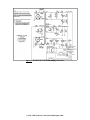
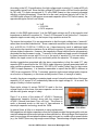
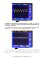
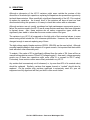
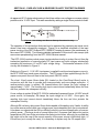
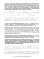
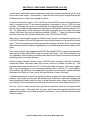
RDF PRODUCTS
Vancouver, Washington, USA 98682
Tel: +1-360-253-2181 Fax: +1-360-635-4615
E-Mail: [email protected] Website: [email protected]
VR-002
Vintage Radio Application Note
RECONDITIONING AND MODERNIZING
THE HEATHKIT HP-13 DC POWER SUPPLY
Rev A03/03-14/vr_apl_002
By Alex J. Burwasser
Original Writing: August 2011
TABLE OF CONTENTS
SECTION I - INTRODUCTION, OVERVIEW, & HONORARIAM ..............................
1
SECTION II - SUMMARY CIRCUIT DESCRIPTION ................................................
2
SECTION III - CLEANING & COSMETICS ..............................................................
4
SECTION IV - SILICON RECTIFIER DIODE REPLACEMENT ................................
A.
DIODE REPLACEMENT ................................................................................
B.
PLACING DIODES IN SERIES ......................................................................
C.
SERIES RECTIFIER DIODE REVERSE VOLTAGE ISSUES .......................
D.
EQUALIZING SERIES RECTIFIER DIODE REVERSE VOLTAGE ..............
5
5
5
6
7
SECTION V - ELECTROLYTIC CAPACITOR REPLACEMENT ..............................
A.
OVERVIEW ....................................................................................................
B.
IMPORTANT CHARACTERISTICS OF ELECTROLYTIC CAPACITORS ....
C.
REPLACEMENTS FOR C3, C4, C8, C9, & C10 (20 uF/450 V) ....................
D.
REPLACEMENTS FOR C11a & C11b (20 uF/150 V) ...................................
E.
MOUNTING C3, C4, C8, C9, C10, C11a, & C11b .........................................
F.
REPLACEMENTS FOR C1 & C12 (10 uF/25 V) ...........................................
G.
REPLACEMENT FOR C6 (100 uF/50 V) .......................................................
H.
RESISTORS ..................................................................................................
8
8
8
9
11
11
12
12
15
SECTION VI - OVER-VOLTAGE & REVERSE POLARITY PROTECTION
ZENER .....................................................................................................................
16
SECTION VII - SWITCHING TRANSISTORS (Q1 & Q2) .........................................
19
SECTION VIII - PARTS VENDORS ..........................................................................
20
LIST OF ILLUSTRATIONS
Figure 1 - Heathkit HP-13B DC Power Supply Schematic ........................................
Figure 2 - Full-Wave Voltage Doubler (w/1N4007 Diodes & Equalizing Resistors) ..
Figure 3 - Electrolytic Capacitors - Then & Now .......................................................
Figure 4 - Chassis Photos (w/annotations) ...............................................................
Figure 5 - Replacement Timing Capacitor C1 ...........................................................
Figure 6 - Voltage Across C6 (220 uF) .....................................................................
Figure 7 - Voltage Across C6 (660 uF total) .............................................................
Figure 8 - Voltage Across C6 (4,420 uF total) ..........................................................
Figure 9 - Over-Voltage and Reverse Polarity Protection Circuitry ...........................
ii
3
7
10
11
12
13
13
14
16
SECTION I - INTRODUCTION, OVERVIEW, & HONORARIUM
This paper is a vintage radio technical document that describes the reconditioning,
modification, and modernization of a Heathkit HP-13 DC power supply. This unit was
designed by Heathkit back in the 1960s to provide the necessary supply voltages for mobile
+12 VDC operation of Heathkit SB- and HW-series HF amateur transceivers and other
equipment.
I procured this unit on Ebay and found it to be in fair condition. Although the unit was
functional and structurally sound, it required significant reconditioning, modification, and
modernization to restore it to “like-new” operational condition. This paper describes this
process in detail along with the necessary supporting technical background.
Although this project did not pose any major technical challenges and was not particularly
difficult, it is my hope that the enhanced technical detail provided will be helpful to other
vintage radio afficionados interested in refurbishing the HP-13 and other power supplies with
similar issues.
Also, visit my N6DC vintage radio website at www.rdfproducts.com/N6DC.Vintage.Radio.htm
for possible revisions to this paper as well as other vintage radio technical articles.
** DANGER **
The Heathkit HP-13 DC power supply contains dangerous high voltages that
can be lethal if contacted. Those intending to work on this power supply
should be well-versed in working on equipment with high voltages present and
be completely familiar with all necessary safety precautions. Those unfamiliar
with these safety precautions or inexperienced in working on equipment
containing high voltages should not open the unit.
HONORARIUM
This paper is written in honor of CWO James D. Henson (U.S. Army, retired) who served this
country over a period of 30 years (1941-1971) that included three wars. CWO Henson built
this HP-13 power supply in 1964 and had it in his possession until 2011. CWO Henson is still
an active amateur radio operator operating as W5BVN out of Killeen, Texas.
1 of 20 - RDF Products - Vancouver Washington USA
SECTION II - SUMMARY CIRCUIT DESCRIPTION
Referring to the schematic of Figure 1, the HP-13 essentially is a transistorized inverter power
supply that accepts +12 VDC (typically from an automotive electrical system), steps up the
resulting AC voltage via a multi-secondary power transformer, and then rectifies and filters the
various secondary voltages to obtain the desired DC outputs. The rated input voltage range
is +12.0 to +14.5 VDC (negative ground). The rated maximum input current is 25 amperes
at full load.
The HP-13 supplies three separate unregulated DC voltage outputs (in addition to a pass-thru
+12 VDC filament voltage output). These DC output voltages are as follows:
High Voltage - The high voltage output is generated by a full-wave voltage doubler. Its rated
output is +800 VDC no-load and +750 VDC @250 mA.
Low Voltage - The low voltage output is generated by a full-wave voltage doubler. Its rated
output is +310 VDC no-load and +300 VDC @150 mA. This low voltage output can be
reduced (for appropriate applications) by selecting the lower voltage tap on the T1 power
transformer secondary. With the lower voltage tap selected, the rated output is +265 VDC noload and +250 VDC @150 mA.
Bias Voltage - An adjustable bias voltage output is generated by a half-wave rectifier. This
is a negative voltage rated at -40 to -130 VDC no-load, depending upon the setting of R10
(Bias Adj.). Current capacity is 20 mA at -130 VDC and 1 mA at -40 VDC.
Capacitive input filters are used for all three DC voltages. The low-voltage supply also
employs an additional series filter choke (L1) followed by an additional shunt filter capacitor
for improved AC ripple reduction.
The inverter switching frequency is nominally 1,500 Hz with loud audible ringing. Unlike
modern inverters that employ switching frequencies above 20,000 Hz (and are inaudible as
a result), inverters built back in the 1960s had to be designed using earlier generation power
transistors that did not offer the enhanced high frequency performance available from modern
power transistors. As a result, these inverters had to use much lower switching frequencies
to operate efficiently.
2 of 20 - RDF Products - Vancouver Washington USA
Figure 1 - Heathkit HP-13 DC Power Supply Schematic
3 of 20 - RDF Products - Vancouver Washington USA
SECTION III - CLEANING & COSMETICS
As stated above, the HP-13 I procured on Ebay was functional and structurally sound, but
somewhat shop-worn and aged. Even so, there was little repair work that needed to be done
aside from replacing missing hardware, retightening some nuts, and conducting a general
clean-up. Since the power output cable was found to be functional and in good condition, it
was left as is.
Fortunately, this unit was assembled very well and required no rework to correct for assembly
errors. In general however, workmanship for Heathkits must be checked carefully given that
the assembly skill of the builder can vary over a wide range. In addition to inspecting solder
joints, all Heathkits should be inspected for solder balls, solder splashes, and any other debris
that may be lodged in the chassis. Of course, all foreign objects should be removed as part
of the cleaning process. Upon completion of the reconditioning, I used cable ties to secure
various wires and non-corrosive silicone RTV to secure various components.
The HP-13 includes a power relay that is used to switch the +12 VDC input power on or off.
It was necessary to clean both sets of relay contacts (these are wired in parallel as per the
schematic of Figure 1) since they were very dirty. I did this by cutting up a 3" x 5" index card
into narrow strips and then soaking the end of one of these strips with spray contact cleaner.
I then ran this soaked strip through the relay contact (manually pushing the relay contacts to
their closed position to generate the friction necessary to clean the contacts as the strips were
pulled through). I then repeated this process with a new strip until the strip pulled through the
contacts clean.
Although the unit looked its age, no cosmetic restoration effort was made aside from general
cleaning. Since my intent was to install this unit out-of-view from the operating console, I saw
no reason to invest any effort into cosmetic restoration.
4 of 20 - RDF Products - Vancouver Washington USA
SECTION IV - SILICON RECTIFIER DIODE REPLACEMENT
A. DIODE REPLACEMENT
The HP-13 rectifiers (D1-D7 from Figure 1) are all 1960s-vintage 1N2071 silicon diodes.
These diodes are rated at 600 PIV (peak inverse voltage) with a maximum average forward
current rating of 750 mA. Although these are old diodes, they are fully adequate for this
application. Even so, being 40+ years old and with newer and better diodes available at very
low cost, it seemed prudent to replace them.
Although there are many modern silicon rectifier diodes available to replace the 1N2071, the
1N4007 is a particularly good choice in that it is widely used, readily available, and very
inexpensive. Rated at 1,000 PIV with a maximum average forward current rating of 1.0 A, the
1N4007 is superior to the 1N2071 in all respects. Being very similar in size to the 1N2071,
the 1N4007 is thus an excellent choice for a fit/form/function replacement for the 1N2071. The
1N4007 can be purchased in small quantities from Digi-Key Corp., Jameco Electronics, and
Mouser Electronics. I purchased mine from Digi-Key Corp. (P/N 1N4007FSCT-ND) along with
replacement electrolytic capacitors as discussed in Section V.
B. PLACING DIODES IN SERIES
As per the schematic of Figure 1, the full-wave voltage doubler employs series diode strings
(D1/D2 and D3/D4) in each leg to increase the PIV ratings. To put some numbers on this, the
required rectifier PIV rating for a full-wave voltage doubler is given by the following equation:
PIV = 2.82 Erms
(1)
where PIV is the maximum peak inverse voltage and Erms is the power transformer RMS
secondary voltage. Although Equation (1) is valid only for a sinusoidal waveform (rather than
the square wave output of T1), using this equation builds in a margin of safety.
An easier way to estimate the required diode total PIV rating for each leg is to simply equate
it to the no-load DC output voltage, which is rated at +800 VDC as per Section II. Since this
is far in excess of the 1N2071 600 PIV rating, the Heathkit engineers correctly decided to
employ two series diodes in each leg for a total nominal rectifier PIV rating of 1,200 volts.
Although at first glance it might seem that the 1,000 PIV rating of the 1N4007 replacement
diodes would eliminate the need for two series diodes, this would be marginal design practice
that would leave this margin a little thin for conservative design standards. Thus, even with
the higher 1N4007 PIV rating, two series diodes should still be used in each voltage doubler
leg.
5 of 20 - RDF Products - Vancouver Washington USA
C. SERIES RECTIFIER DIODE REVERSE VOLTAGE ISSUES
Although I have always given the Heathkit engineers high marks for their circuit designs, I
have to offer an (amicable) criticism of their practice of omitting shunt voltage equalizing
resistors in their series rectifier diode strings (this topic is discussed in more depth in Section
IV-D below). In a paper I recently read on Heathkit upgrades for the SB-200 linear amplifier,
this same topic was addressed.
As it happens, the SB-200 employs a similar full-wave voltage doubler circuit that employs the
same 1N2071 silicon rectifier diodes. Since the SB-200 requires a +2,400 VDC plate supply,
however, eight diodes are employed in each leg to obtain the necessary PIV rating. However,
no shunt voltage equalizing resistors are employed.
The author of this paper tactfully addresses this questionable Heathkit design practice as
“remarkable”, but then goes on to say that with modern diodes this practice is acceptable.
Once again, I have to offer an amicable disagreement.
To get back to the basics on this subject, the salient issue is the silicon rectifier diode back
resistance. If we place two 1,000 PIV diodes in series to effectively increase the total PIV
rating to 2,000 volts, our implicit assumption is that both diodes have nearly the same back
resistance. If this is not the case, there will be “voltage hogging”. To explain, if one of the
diodes has (for example) twice the back resistance of the other, then that diode with the higher
back resistance will drop 2/3 (rather than ½) of the total reverse voltage. With simple
arithmetic, we can see that the total effective PIV rating of these two series diodes would then
be only 1,500 rather than 2,000 volts (i.e., with 1,500 reverse volts applied across the series
pair, the higher back resistance diode will see its maximum rated 1,000 PIV).
To resolve this matter, we need a better understanding of the characteristics of diode back
resistance. Unfortunately, diode back resistance is not directly specified in the 1N4007 diode
data sheet. The diode specification most closely related to back resistance is the reverse
(leakage) current. The “typical” reverse current for a 1N4007 at its maximum 1,000 volts
reverse voltage at 25EC is given as 0.05 microamperes (which corresponds to a 20,000
megohm back resistance).
However, this same data sheet lists the “maximum” reverse current for this same diode as 10
microamperes (which corresponds to a far lower 100 megohm back resistance). This in itself
is a huge variation, but it even gets worse. At 100EC, the “typical” and “maximum” numbers
are given as 1.0 and 50 microamperes, respectively, corresponding to back resistances of
1,000 megohms and 20 megohms, respectively.
Clearly, diode back resistance is an uncontrolled parameter that is all over the place, varying
both from unit to unit and over temperature. Given the above numbers, it seems amazing that
Heathkit’s practice of placing these diodes in series without shunt voltage equalizing resistors
could ever have worked. Equally clearly, the problem cannot be solved simply by substituting
modern diodes since back resistance is still an uncontrolled and unspecified diode
characteristic. I have to think that what pulled Heathkit through on this (aside from a generous
dose of luck) was that most of the diodes supplied with their kits must have come from the
same batch.
6 of 20 - RDF Products - Vancouver Washington USA
D. EQUALIZING SERIES RECTIFIER DIODE REVERSE VOLTAGE
The issues associated with the highly variable back resistances of series diodes have been
well-known for many years along with a mature and time-proven solution. Essentially, the
remedy is to place shunt “swamping” resistors of the same value across each diode in the
series string. If this resistor value is much lower than the diode back resistance, then the
effective back resistance is essentially the value of this resistor and the voltage will divide
nearly equally across each diode/resistor shunt pair.
Although there is likely no truly “optimum” value for this shunt resistor, the 1974 ARRL Radio
Amateur’s Handbook in its chapter on AC operated power supplies provides the following ruleof-thumb:
Rs = PIV x 500
(2)
where Rs is the required value of shunt resistance and PIV is the diode rated peak inverse
voltage. Essentially then, the author recommends using 500 ohms of resistance per diode
PIV rating. For a 1N4007 diode rated at 1,000 PIV, the required resistor value would be
500,000 ohms. A 470,000 ohm resistor is thus selected as a good-match standard value.
Again referring to the HP-13 schematic of Figure 1, the 800 volt open-circuit high-voltage is
dropped across four rectifier diodes. If 470,000 ohm voltage equalizing resistors are placed
across each diode, then the voltage across each 470,000 ohm resistor is 800/4 = 200 volts.
The resulting power dissipation in each of these resistors can then be computed by Ohm’s
Law as E x E/R = 200 x 200/470,000 = 0.085 watts.
Purely from the standpoint of power dissipation, we could use 1/8 watt 5% carbon film
resistors. However, resistors also have maximum voltage ratings and it would be unsafe to
use a 1/8 watt resistor for this high-voltage application. 1/4 watt 5% carbon film resistors have
a rated maximum working voltage of 250 VDC which would probably be adequate. However,
it is better to use ½ watt 5% carbon film resistors with their higher rated maximum working
voltage of 350 VDC. The modified diode section of the full-wave voltage doubler is illustrated
in Figure 2.
Figure 2 - Full-Wave Voltage Doubler
Modified to Include 1N4007 Silicon Diodes
and Shunt Voltage Equalizing Resistors
Figure 4 is a photo showing D1-D4 (all 1N4007s) mounted piggy-back on their associated
470k 1/2W equalizing resistors (located behind C3 and C4).
7 of 20 - RDF Products - Vancouver Washington USA
SECTION V - ELECTROLYTIC CAPACITOR REPLACEMENT
A. OVERVIEW
Electrolytic capacitors (especially high-voltage ones) are likely not to be reliable after 40+
years of service. Although the electrolytic capacitors in my HP-13 were functional, I decided
to replace them for this reason.
Of all the HP-13 restoration tasks, replacing the 10 electrolytic capacitors turned out to be the
most difficult and time consuming. Although high-voltage electrolytic capacitors are still
available, there are no longer any direct fit/form/function replacements for the original 1960svintage electrolytic capacitors employed in the HP-13. As a result, adaptations must be made
to accommodate the different sizes and footprints of modern electrolytic capacitors.
On the positive side, modern electrolytic capacitors are much smaller, better performing, and
more reliable than their 1960s-vintage predecessors. Since electrolytic capacitors have
service lives that are much shorter than nearly all other components aside from vacuum tubes
and dial lights, I chose premium-grade replacements.
In the following paragraphs, the important characteristics of high-voltage electrolytic capacitors
are discussed, followed by identification of specific modern substitutes for the obsolete
originals. Suggestions are then made as to how to install these modern substitutes in the HP13.
B. IMPORTANT CHARACTERISTICS OF ELECTROLYTIC CAPACITORS
1. Capacitance and Voltage Rating - Replacement electrolytic capacitors should have
capacitances and voltage ratings equal to or greater than the originals.
2. Service Life - The service life of electrolytic capacitors is typically in the order of
thousands of hours, which surprisingly is only somewhat better than that of vacuum
receiving tubes. Service life is highly dependent upon operating temperature, applied
voltage, and applied ripple current. When operated conservatively, electrolytic capacitors
last far longer than when they are operated near their maximum ratings.
3. Temperature Rating - The original electrolytic capacitors employed in the HP-13 (and
most non-military electronic equipment built in the 1960s) are rated for operation up to
+85EC. Keeping in mind that the service life of electrolytic capacitors is typically in the
order of thousands of hours and that this service life degrades at higher temperatures, I
recommend that premium grade capacitors rated for operation up to +105EC be used for
longest service life.
4. ESR (Equivalent Series Resistance) - Since electrolytic capacitors dissipate a certain
percentage of the charge applied to them into heat, they are characterized as having an
8 of 20 - RDF Products - Vancouver Washington USA
equivalent series resistance. This ESR is frequency sensitive, but is mostly constant over
the frequency range of interest (under 1,000 Hz) for high-voltage power supplies. Low
ESRs are desirable for good performance and long life.
5. AC Ripple Current - Electrolytic capacitors employed as power supply filters are subject
to AC ripple current as a consequence of the fact that there is always some AC ripple
voltage across them. Since this ripple current flows through the capacitor ESR, heat is
generated that shortens capacitor life. It is therefore important that electrolytic capacitors
be selected both for high ripple current capacity and low ESR.
C. REPLACEMENTS FOR C3, C4, C8, C9, & C10 (20 uF/450 V)
C3, C4, C8, C9, and C10 are the five 20 uF/450 V electrolytic capacitors mounted in a row at
the rear-most section of the HP-13 circuit board (adjacent to the 2 watt resistors) . As per the
schematic of Figure 1, C3/C4 are used in the high-voltage supply while C8-C10 are used in
the low-voltage supply. Since the high-voltage supply imposes the most demanding
requirements on these capacitors, we will focus primarily on C3/C4.
A vendor search to locate a 20 uF/450 V replacement electrolytic capacitor was unsuccessful.
However, a premium-grade 47 uF/450 V manufactured by Panasonic (P/N EEU-EE2W470)
was available from Digi-Key Corp. (P/N 13677-ND). The relevant specifications for this
capacitor are as follows:
Temperature Range:
Rated ESR @ 120 Hz:
Rated Ripple Current (120 Hz/105EC):
-25EC to +105EC
6.77 ohms
1.2 amperes
The rated service life is dependent upon a number of variables, but was very favorable
compared to other capacitors that were also considered.
To determine the suitability of this capacitor for the application at hand, we must first calculate
the overall impedance of this capacitor, which comprises the 6.77 ohm ESR in series with the
capacitive reactance at the 3,000 Hz ripple frequency (i.e., twice the rated inverter 1,500 Hz
switching frequency for the full-wave voltage doubler). First, we compute the capacitive
reactance:
Xc = 1/(2 x π x F x C)
= 1.13 ohms
(3)
where Xc is the capacitive reactance, π is 3.14159, F is 3,000 Hz, and C is 47 uF.
Next, the total impedance is found by vectorially adding Xc and the ESR as follows:
Z = Square Root (Xc x Xc + ESR x ESR)
= Square Root (1.13 x 1.13 + 6.77 x 6.77)
= 6.86 ohms
9 of 20 - RDF Products - Vancouver Washington USA
(4)
According to the HP-13 specifications, the high-voltage ripple is rated at 1% under a 250 mA
(presumably typical) load. Since the high-voltage DC output under a 250 mA load is specified
as 750 volts, 1% ripple corresponds to 7.5 volts RMS (based on the commonly-accepted
definition of ripple percentage). Given this to be the case, and given that only half of this 7.5
volt RMS ripple voltage (Vr) will appear across each capacitor (since C3/C4 are in series), the
approximate ripple current is as follows:
Ir = Vr/Z
= 3.25/6.86
= 0.474 amperes
(5)
where Ir is the RMS ripple current, Vr is the RMS ripple voltage, and Z is the capacitor total
impedance as defined in equation (4). Since 0.474 amperes is well below the 1.2 ampere
capacitor ripple current rating, we can expect long capacitor service life.
The reason that equation (5) is an approximation is that the ripple voltage has a “sawtooth”
rather than sinusoidal characteristic. Since a sawtooth waveform has odd-order harmonics
(e.g., at 9,000 Hz, 15,000 Hz, 21,000 Hz, etc.), these harmonics result in additional ripple
current since the capacitive reactance Xc as defined in equation (3) progressively diminishes
at these higher frequencies. However, the magnitude of these harmonics also progressively
diminishes as they increase in order. To account for the additional ripple current contributed
by these harmonics we can add 15% or so to the result of equation (5), but even with this
addition the ripple current is still very comfortably within the capacitor 1.2 ampere rating.
Another imperfection associated with the above computations is that the rated 6.77 ohm
capacitor ESR is specified for the 100-120 Hz ripple frequency (typically associated with fullwave rectifiers operated from standard 100-120 Hz AC mains), rather than for the inverter
3,000 Hz ripple frequency. It is therefore reasonable to expect that the ESR is different at
3,000 Hz as compared to 120 Hz. Fortunately, capacitor ripple current ratings tend to improve
as a function of frequency, so this issue actually works in favor of a margin of safety.
In reality, the above computation overstates ripple current Ir since the substitution of the larger
capacitor (47 uF versus 20 uF) substantially reduces the ripple voltage Vr. As a result, the
margin of safety is further improved.
Since ripple voltage Vr across C8/C9/C10 used in the lowvoltage supply is even lower, this same capacitor can be used
with an even greater margin of safety.
Figure 3 is a photo of the modern 47 uF/450 V Panasonic
replacement capacitor (bottom) along with the original 20
uF/450 V General Instrument Corp. unit (top). This picture is
worth a thousand words on the topic of improvements in
electrolytic capacitor technology since the 1960s.
Figure 3 - Electrolytic
Capacitors - Then & Now
In general, there is little or no downside to using replacement
filter capacitors with higher capacitance than the originals provided that good quality units are
used with adequate ripple current ratings as discussed above. Although larger filter capacitors
result in more surge current when the power supply is turned on, modern silicon power diodes
(e.g., the 1N4007) have very high surge current ratings. The advantage of higher capacitance
10 of 20 - RDF Products - Vancouver Washington USA
units, of course, is lower ripple voltage.
D. REPLACEMENTS FOR C11a & C11b (20 uF/150 V)
As per the schematic of Figure 1, C11 is a dual electrolytic type (both sections 20 uF/150 V)
that is used to filter the rectified bias voltage (-130 VDC nominal maximum). Although the 47
uF/450 V capacitors used for the high- and low-voltage supplies as discussed above are
higher rated than necessary for use in this bias supply (both in terms of capacitance and
voltage rating), I decided to use them since I had them on hand and they were not very
expensive.
E. MOUNTING C3, C4, C8, C9, C10, C11a, & C11b
Although the 47 uF/450 V capacitors selected to replace C3/C4/C8/C9/C10 offer great
performance and reliability, they did not fit the HP-13 PC board patterns that were made for
these capacitors. While the replacement capacitors are much smaller than the originals, the
bigger problem is that they are radial lead units (whereas the originals are axial lead units).
Since modern capacitors are designed mostly for PC board mounting, it is increasingly difficult
to find axial lead capacitors.
Figure 4 - Chassis Photo
(C3/C4/C8/C9/C10/C11a/C11b & D1-D4 replacements annotated)
11 of 20 - RDF Products - Vancouver Washington USA
Since these capacitors are small enough to be mounted upright, I mounted them as pictured
in Figure 4. Although the capacitor leads were long enough to reach the original component
PC board mounting holes, these capacitors were not well-secured to the board using this
unorthodox mounting technique.
To correct this issue, I staked these capacitors down to the board using RTV (RTV is a form
of silicone sealant). I used Permatex Part 66B (which is non-corrosive and available in many
hardware and auto supply stores), but many other types are equally suitable. After allowing
several hours to cure, the RTV secured these capacitors firmly to the PC board.
F. REPLACEMENTS FOR C1 & C12 (10 uF/25 V)
As per the schematic of Figure 1, C1 and C12 (both 10 uF/25 V) are the inverter timing
capacitors that are used to establish the 1,500 Hz (nominal) switching frequency. Although
it was not clear to me what the ripple current requirements were for these capacitors, I
decided to once again go with premium-grade replacements.
I selected 10 uF/63 V capacitors manufactured by
Panasonic (P/N EEU-EB1J100) and available
from Digi-Key Corp. (P/N P13138-ND). As
expected, these capacitors are much smaller
than the original units. C1 is shown in Figure 5
(just below 270 ohm resistor R1). I staked-down
both C1 and C12 with RTV.
Although the nominal inverter switching
frequency is 1,500 Hz, the actual measured
switching frequency with the original C1/C12
capacitors was near 1,600 Hz. This frequency
rose slightly to near 1,700 Hz with the
replacement capacitors.
Figure 5 - Replacement Timing Capacitor C1
G. REPLACEMENT FOR C6 (100 uF/50 V)
Referring to the schematic of Figure 1, C6 is a large bypass capacitor intended to hold the T1
inverter transformer center tap at AC ground. In conjunction with choke L2, it also serves to
help filter inverter switching spikes from the +12 VDC input.
Since there was no question in my mind that C6 needed to be a high-quality capacitor, I
selected a premium-grade 220 uF/50 V unit manufactured by Panasonic (P/N EEU-EB1H221)
and available from Digi-Key Corp. (P/N P13131-ND). To my surprise, however, this capacitor
became very warm to the touch when the power supply was powered-up. Probing this
replacement capacitor with an oscilloscope, the voltage across it appeared as in Figure 6 (no
load on power supply).
12 of 20 - RDF Products - Vancouver Washington USA
Figure 6 - Voltage Across C6 (220 uF)
As per this photo, the magnitude of the switching spikes is 3 VPP, which is very large for a
+12 VDC input. Clearly, the large ripple current resulting from these spikes was responsible
for the capacitor overheating.
To improve things, two additional 220 uF/50 V capacitors were added in parallel with C6 (for
a total of 660 uF). The result of this additional capacitance is shown in Figure 7.
Figure 7 - Voltage Across C6 (660 uF total)
As per this photo, including the additional 440 uF of capacitance cut the switching spike
magnitude in half to approximately 1.5 VPP. Also, the additional capacitance eliminated the
heating problem as a result of the fact that this additional capacitance reduced ripple voltage
and distributed the lesser resulting ripple current through three (rather than one) capacitors.
13 of 20 - RDF Products - Vancouver Washington USA
Figure 8 - Voltage Across C6 (4,420 uF total)
Although this was a significant improvement, it seemed that this ripple magnitude was still high
(especially considering the fact that there was no load on the power supply). Also, it seemed
that further improvement would require a large amount of additional capacitance. My next
step then was to add eight 470 uF/25 V capacitors in parallel with the three 220 uF/50 V units
already in place. With this very large amount of capacitance, the ripple voltage significantly
diminished as illustrated in Figure 8.
These additional 470 uF/25 V capacitors were used since they were already in stock. These
units are manufactured by Panasonic (P/N ECA-1EHG471) and are available from Digi-Key
Corp. (P/N P5543-ND). These capacitors are visible in Figure 4. (Note that the 470 uF/25 V
capacitors are grouped into sets of four and bundled together using heat-shrink tubing.)
With the benefit of hindsight, however, it is clear that this piecemeal and incremental approach
leaves much to be desired. Subsequent to the photo shoot for Figure 4, these capacitors
were all removed and replaced by a single 4,700 uF/35V electrolytic capacitor suitable for this
application. This capacitor is manufactured by Panasonic (P/N ECA1VHG472) and available
from Digi-Key Corp. (P/N P5558-ND). This unit has a very high ripple current rating (1.91
amperes).
In closing, the original 100 uF/50 V capacitor used for C6 appears to have been very marginal
for the intended application. 100 uF is far to small to provide good ripple filtering, and it is
almost certain that this capacitor was being operated far in excess of its ripple current rating.
Also, even though Heathkit chose a 50 V capacitor, in most mobile +12 VDC applications it
is safe to use 25 V capacitors. This is especially the case if a power Zener diode is employed
as an over-voltage clamp. This useful input power protection technique is discussed in detail
in Section VI.
14 of 20 - RDF Products - Vancouver Washington USA
H. RESISTORS
Although a discussion of the HP-13 resistors might seem outside the purview of this
discussion of its electrolytic capacitors, replacing the capacitors also presents an opportunity
tp check these resistors. More specifically, significant disassembly of the HP-13 is required
to replace its capacitors. As a result, most of the resistors will have at least one lead
disconnected during this process so it is easy to check their values with an ohmmeter.
Although resistors are not usually considered as high-maintenance components prone to
failure, the resistors used in the HP-13 are all power resistors and have thus been subjected
to thermal stress. Also, these resistors are all carbon composition types, which are
significantly less stable in value than the more modern carbon film types.
The resistors in my HP-13 all measured on the high side of their nominal values, in some
cases having drifted outside the 10% tolerance specification. However, the values had not
changed enough to warrant replacing any of them.
The high-voltage supply bleeder resistors (R3/R4; 100k/2W) are the most critical. Although
a modest upward change in their values is of no great concern, it is important that their values
track with each other reasonably well.
To explain, if the value of R3 is significantly different than the value of R4, there will be an
unequal voltage division across C3 and C4 (“voltage hogging”). As a result, voltage appearing
across one of these two capacitors might come close to or exceed its 500 V rating.
Fortunately, these resistor values were closely matched in my HP-13.
Any resistor that is excessively out of tolerance (i.e., by more than 20% of its nominal value)
should be replaced. Similarly, resistors that appear burned or “cooked” should also be
replaced. On the positive side, resistors employed in extensively used 40+ year old
equipment are fully aged and will likely not drift in value much further.
15 of 20 - RDF Products - Vancouver Washington USA
SECTION VI - OVER-VOLTAGE & REVERSE POLARITY PROTECTION ZENER
An apparent HP-13 design shortcoming is that it has neither over-voltage nor reverse-polarity
protection at its 12 VDC input. This was remedied by adding a single Zener protection diode.
Figure 9 - Over-Voltage and Reverse Polarity Protection Circuitry
The operation of this protection diode can best be explained by examining an actual circuit
where it has been successfully employed. Figure 9 is a simplified schematic of the input
power circuitry of the RDF Products DFP-1000A DF bearing processor (the predecessor to
the current DFP-1000B). The following detailed explanation of this circuit is an excerpt (with
some minor paraphrasing) from the DFP-1000A Service manual:
“The DFP-1000A contains robust power input protection circuitry to protect the unit from the
inadvertent application of reverse-polarity DC input power and input voltages substantially
exceeding the maximum +16 volt DC input voltage rating. The essential elements of this
circuitry are illustrated in Figure 9.
Referring to Figure 9, 11-16 VDC input power is applied from the external power source to
the DFP-1000A rear-panel power connector. This DC power is then applied through the 2.5
ampere rear-panel fuse and then to the front-panel ON/OFF switch.
The shunt 18-volt power Zener diode (D9, located on the Front-Panel Board) works in
conjunction with the fuse to provide both reverse-polarity and over-voltage protection. If
reverse-polarity power is applied, D9 forward-biases and clamps the input voltage at
approximately -1 VDC. The resulting high input current almost immediately blows the fuse
and thus protects the subsequent circuitry.
If over-voltage is applied (if the DFP-1000A is inadvertently powered from a +28 VDC aircraft
power source, for example), D9 clamps the input voltage at +18 VDC. Once again, the
resulting high input current almost immediately blows the fuse and thus protects the
subsequent circuitry.
Although D9 is a heavy-duty power Zener diode capable of dissipating up to 5 watts, its ability
to survive reverse-polarity and over-voltage power inputs depends upon the circumstances.
It has been our experience that D9 is sufficiently robust to survive the application of reversepolarity power. (The large inrush of current blows the 2.5 ampere fuse before the junction
temperature of D9 rises to the point where the diode junction fuses, although it is possible that
this might not be the case if the current capacity of the power source is sufficiently high.) If
D9 survives (as is usually the case), it is necessary to replace only the 2.5 ampere fuse.
16 of 20 - RDF Products - Vancouver Washington USA
In cases where over-voltage is applied, however, it has been our experience that D9's junction
typically fuses before the 2.5 ampere fuse blows (although it is possible that D9 can survive
if the external power source has a sufficiently low current-limiting threshold), resulting in both
a blown fuse and D9 presenting a direct short circuit as a result of its fused junction. In this
case, it is necessary to replace both the 2.5 ampere fuse and D9. Even so, the input power
protection circuitry has still functioned effectively, preventing major DFP-1000A damage at the
expense of requiring replacement of only two inexpensive components.”
Since the HP-13 12 VDC input circuitry is protected by a 30 ampere circuit breaker rather than
the faster acting 2.5 ampere fuse employed in the DFP-1000A, it is probable that the 1N5355B
Zener diode would not survive the application of reverse-polarity power. Even so, this
inexpensive and readily replaceable part would still protect the HP-13 power transformer and
power transistors (parts that would likely be irreplaceable or very hard to find at best).
An incidental benefit of this power protection Zener is that it limits input voltage spikes to 18
volts. As a result, the voltage rating of C6 need be no greater than 25 V for safe operation.
(The 4,700 uF capacitor substituted for C6 as discussed above is rated at 35 V only because
this 35 V capacitor has a higher ripple current rating than the comparable 25 V unit.)
I strongly recommend adding this inexpensive part to the HP-13. Referring to the HP-13
schematic of Figure 1, the 1N5355B cathode be connected to the positive terminal of C6 (i.e.,
at the power transformer center tap) and the anode should be connected to ground.
A possible amendment to this technique would be to select a similar power Zener with a lower
forward voltage rating. In the case of the DFP-1000A/B discussed above, the maximum
specified input voltage is 16 VDC. Since the forward voltage tolerance for this Zener family
is +/-5%, we decided to use the 18 volt 1N5355B to be absolutely certain that there would be
no unwanted Zener forward conduction at the maximum specified 16 VDC input. Also, we
validated this choice by confirming that the DFP-1000A/B would not suffer damage from
prolonged exposure to an 18 VDC input.
In the case of the HP-13, however, the maximum rated input voltage is only 14.5 VDC so it
would be reasonable to substitute a Zener with a lower forward voltage rating. The 16 volt
1N5353B would be a good candidate, and possibly even the 15 volt 1N5352B.
The downside of using a Zener with too low a forward voltage rating is that it can conduct and
gulp large amounts of current at too low an input voltage. As a case in point, if the 15 volt
1N5352B is selected for the HP-13, a Zener at the bottom edge of the rated +/-5% tolerance
would begin conducting at 14.25 VDC (which would unfortunately be inside the HP-13 14.5
VDC maximum rated input voltage specification).
Ultimately, this is a matter of deciding how far we want to go to protect the HP-13. As
discussed in Section VII, the germanium switching transistors (Q1 & Q2) would likely be very
difficult to replace. Given this reality, the prudent decision might well be to use a lower voltage
Zener, particularly if the applied DC voltage is not likely to rise too close to the HP-13 14.5
VDC maximum rated input.
To further amplify on this, a typical lead-acid battery can reach a 14.5 terminal voltage under
hard charging although lower terminal voltages are more typical. If we really wanted to
finesse this, we could buy a small quantity of nominal 14 volt (1N5351B) and 15 volt
17 of 20 - RDF Products - Vancouver Washington USA
(1N5352B) Zeners and then select them by careful measurement to find one with forward
voltage threshold very close to 14.5 volts.
1N5355B Zener diodes are available from many sources including Digi-Key Corp. (P/N
1N5355BRLGOSCT-ND). This part is also available from Mouser Electronics (P/N 610CZ5355B). The 1N5351B and 1N5352B are also available from these same sources.
18 of 20 - RDF Products - Vancouver Washington USA
SECTION VII - SWITCHING TRANSISTORS (Q1 & Q2)
It would seem reasonable to want to replace the two power switching transistors in a 40+ year
old inverter power supply. Unfortunately, I found this task to be far from straightforward and
ultimately decided to leave the originals in service.
As per the schematic of Figure 1, Q1 and Q2 are identical PNP power switching transistors
used in conjunction with T1 and various peripheral components to form a 1,500 Hz power
oscillator. Although the circuitry is conventional and straightforward, the HP-13 assembly
manual does not identify these transistors other than by the Heathkit house part number (41760). An examination of the transistors themselves revealed only this same house part
number, Motorola’s logo and the additional identifier “SP838-1". None of my Motorola data
manuals (even the very old ones dating back to the 1970s) list the SP838.
Based on an internet search of various Heathkit users’ groups, this transistor appears to be
a 45 volt 25 ampere 100 watt PNP germanium type that has been out of production for many
years. This is not surprising given that germanium transistors, as far as I know, are no longer
manufactured and have long been supplanted by more reliable and temperature-stable silicon
types.
One of the postings I found suggested the NTE179 and the ECG197 as generic replacements
(although the poster stated that he had not actually tried them). Also, these transistors are
very expensive, which is likely an indication that they are no longer in production and that the
remaining stocks are nearly depleted.
Another posting claimed success using a 2N6330 silicon transistor, although it reported
occasional inverter mis-starts where the inverter would not oscillate at power-up. (The
reported remedy was to switch the HP-13 off and then back on again.) This issue suggests
that it may be necessary to use a matched transistor pair for the HP-13 to start reliably.
Unfortunately, the 2N6330 is not available from my primary semiconductor suppliers (Mouser
Electronics and Digi-Key Corp.) and is likely an obsolete or hard-to-find part.
I ultimately decided just to leave the original transistors in place since they appeared to work
properly. My primary concern was that attempting a substitution might risk damaging the
power transformer (which would force me to scrap the whole power supply since it would be
very difficult to find a replacement transformer from any source other than another HP-13).
Even so, I see no reason why the two germanium transistors could not be replaced with
modern silicon types. This task would, of course, have to be done carefully and with the full
expectation that some circuit redesign might be necessary. Such an effort would be a worthy
follow-on project.
19 of 20 - RDF Products - Vancouver Washington USA
SECTION VIII - PARTS VENDORS
As discussed above, I purchased the necessary parts from Digi-Key Corp. since they have
an excellent selection of capacitors. Other parts vendors with good parts selections and
reasonable minimum order requirements are Jameco Electronics and Mouser Electronics.
Contact information is as follows:
Digi-Key Corp. - www.digikey.com
Jameco Electronics - www.jameco.com
Mouser Electronics - www.mouser.com
<>
Post Note:
I received a message from reader Burkhard Riemer in Germany who has also reconditioned
an HP-13. Burkhard advises that a European source for capacitors and other components
can be found at the following link:
http://www.die-wuestens.de/dindex.htm?/katalog.htm
20 of 20 - RDF Products - Vancouver Washington USA