1
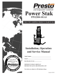
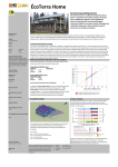
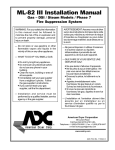
Dock Lift
Model:
PDL60-60
Installation, Operation
and Service Manual
Model Number ___________________
Serial # _________________________
Date Placed in Service _____________
IMPORTANT: READ CAREFULLY
BEFORE INSTALLING OR OPERATING LIFT
Part orders are subject to a $50 minimum charge.
September 2015
This manual was current at the time of printing. To obtain the latest, most updated version,
please contact the Customer Service Department or go to our website: www.PrestoLifts.com
-- you will find a complete list of current Owner’s Manuals to print.
PRESTO OWNER’S MANUAL
Page 2 DOCK LIFT
Contents
INTRODUCTION............................................................................... 4
RESPONSIBILITY OF OWNERS AND USERS............................... 5
SAFETY ALERT SYMBOLS AND SIGNAL WORDS..................... 6
SAFE SERVICING OF THE LIFT ..................................................... 7
SAFETY .............................................................................................. 8
INSTALLATION INSTRUCTIONS ................................................. 8
Preparation ......................................................................... . 8
Positioning the Lift ....................................................... ....... 9
Hydraulic Connections .................................................... .... 9
Electrical Connections ..................................................... .. 10
Testing ......................................................................... ...... 10
Completing Installation .................................................... . 10
OPERATING INSTRUCTIONS ..................................................... 11
Operating Procedure ........................................................ .. 11
MAINTENANCE .......................................................................... .. 13
Hazards .............................................................................. 13
Routine Periodic Maintenance ......................................... . 13
TROUBLESHOOTING .................................................................... 14
Troubleshooting Check List ............................................. . 14
Electrical Connections for Single-Phase AC................... ... 18
Electrical Connections for Three-Phase AC ...................... 19
Ordering Replacement Parts .......................................... .... 22
RESTOCKING POLICY................................................................... 23
WARRANTY............................................................................ ........ 24
List of Figures
Fig. 1 Safe Servicing of Lift ............................................................ 5
Fig. 2 Mount the Lift Securely ........................................................ 8
Fig. 3 Using Lifting Eyes ............................................................... . 9
Fig. 4 Center the Load ................................................................... 11
Fig. 5 Secure the Load .................................................................. . 11
Fig. 6 Pinch Points ......................................................................... 12
Fig. 7 Parts Identification ............................................................... 16
Fig. 8 Standard 3.2 HP Power Unit ................................................... 17
Fig. 9 Hydraulic Pump and Down Valve ......................................... 17
Fig. 10 Electrical Connections,
Lifts Wired for Single-Phase AC ......................................... 18
Fig. 11 Wiring Diagram,
Lifts Wired for Single-Phase AC - without limitswitch ...... 18
Fig. 12 Electrical Connections,
Lifts Wired for Three-Phase AC .......................................... 19
Fig. 13 Wiring Diagram,
Lifts Wired for Single-Phase AC - with limitswitch............ 20
Fig. 14 Hydraulic Connections......................................................... 20
Fig. 15 Hydraulic Diagram .............................................................. 21
Table 1 Electrical Interface, Supplied by Customer............. 21
Table 2 Hydraulic Oil Specifications ................................... 21
PRESTO OWNER’S MANUAL Page 3 DOCK LIFT
SECTION 1
INTRODUCTION
The PDL series includes Presto Lifts Dock Lift scissor table. The basic PDL series lift may
be modified in many ways to meet special requirements for load capacity, vertical travel, table
size, power source, and other characteristics. PDL lifts can also be fitted with many optional
accessories and modifications to suit the customer’s needs.
This manual contains information to acquaint you with the safe and proper installation, use, and
upkeep of an PDL series lift table. You should ensure that this manual is available to personnel
working with and on the lift table and require its use by these personnel.
PDL lift tables are designed for lifting and vertical positioning of equipment and materials in a
wide variety of industrial settings. The instructions set forth in this manual are not necessarily allinclusive, as Presto Lifts cannot anticipate all conceivable or unique situations.
In the interest of safety, please read all of this manual carefully, and be familiar with its
contents before you install, use, or service the PDL Lift Table. If you have any questions
about any of the instructions in this manual, please contact your dealer or Presto Lifts.
Presto’s product warranty is shown on the back cover of this manual.
This instruction manual is not intended to be or to create any other warranty, express or
implied, including any implied warranty of merchantability or fitness for a particular
purpose, all of which are hereby expressly excluded.
As set forth more specifically in the product warranty, Presto’s obligation under that warranty
is limited to the repair or replacement of defective components, which shall be the buyer’s sole
remedy, and Presto Lifts shall not be liable for any loss, injury, or damage to persons or property,
nor for any direct, indirect, or consequential damage of any kind resulting from the PDL lift table.
PRESTO OWNER’S MANUAL
Page 4 DOCK LIFT
Responsibility of Owners and Users
Inspection and Maintenance
The device shall be inspected and maintained in proper working order in accordance with Presto’s
owner’s manual.
Removal from Service
Any device not in safe operating condition such as, but not limited to, excessive leakage, missing
rollers, pins, or fasteners, any bent or cracked structural members, cut or frayed electric, hydraulic,
or pneumatic lines, damaged or malfunctioning controls or safety devices, etc. shall be removed from
service until it is repaired to the original manufacturer’s standards.
Repairs
All repairs shall be made by qualified personnel in conformance with Presto’s instructions.
Operators
Only trained personnel and authorized personnel shall be permitted to operate PowerStak.
Before Operation
Before using the device, the operator shall have:
• Read and/or had explained, and understood, the manufacturer’s operating instructions and safety
rules.
• Inspected the device for proper operation and condition. Any suspect item shall be carefully examined and a determination made by a qualified person as to whether it constitutes a hazard. All
items not in conformance with Presto’s specification shall be corrected before further use of the
PowerStak.
During Operation
The device shall only be used in accordance with this owner’s manual.
• Do not overload.
• Ensure that all safety devices are operational and in place.
Modifications or Alterations
Modifications or alterations to any Presto industrial positioning equipment shall be made only with
written permission from Presto.
PRESTO OWNER’S MANUAL Page 5 DOCK LIFT
SAFETY ALERT SYMBOLS AND SIGNAL WORDS
The safety of all persons operating, maintaining, repairing, or in the vicinity of this equipment is of paramount
concern. This is a powerful machine with moving parts, and is capable of causing personal injury if proper precautions are not taken. Therefore, throughout this manual, certain hazards have been identified which may occur in
the use of the machine, and there are appropriate instructions or precautions which should be taken to avoid these
hazards. In some cases, there are consequences which may occur if instructions or precautions are not followed.
Below are the symbols and signal words along with their definitions referenced from ANSI Z535.4 - Product Safety
Signs and Labels.
Safety Alert Symbols
These are the safety alert symbols.. They are used to alert you to potential physical injury hazards. Obey all safety messages that follow this symbol to avoid possible injury or death.
For use with DANGER signal word
(Red Background)
For use with WARNING signal word
(Orange Background)
For use with CAUTION signal word
(Yellow Background)
Signal Words
The meaning of different signal words as defined by ANSI Standard Z535.4 indicates the relative
seriousness of the hazardous situation.
DANGER indicates a hazardous situation which, if not avoided,
will result in death or serious injury.
(Red Background)
WARNING indicates a hazardous situation which, if not avoided,
could result in death or serious injury.
(Orange Background)
(Yellow Background)
CAUTION, used with the safety alert symbol, indicates a hazardous situation which, if not avoided, could result in minor or
moderate injury.
NOTICE is used to address practices not related to personal
injury.
(Blue Background)
SAFETY
INSTRUCTIONS
SAFETY INSTRUCTIONS (or equivalent) signs indicate safetyrelated instructions or procedures.
(Green Background)
PRESTO OWNER’S MANUAL
Page 6 DOCK LIFT
Rotate the chocks
into position
SAFE SERVICING OF THE LIFT
WARNING !
Only authorized personnel should perform inspection or maintenance and service procedures. Unauthorized personnel attempting these procedures do
so at the risk of severe injury or death.
Working
position
DANGER !
Working
position
Failure to properly adhere to lift blocking procedures
is to risk the sudden and uncontrolled descent of the
lift during maintenance or inspection. A falling lift
can cause severe injury or death.
Storage
position
Figure 1 – Safe Servicing of Lift
This procedure describes the only factory-approved
method of working under a lift. Follow these instructions
EVERY time you plan to reach or crawl beneath the lift to
perform service or maintenance – no matter how momentary
that might be.
If the factory-provided maintenance device is damaged
or missing, stop immediately and consult the factory for assistance. The manufacturer is not liable for your failure to
use the approved maintenance device(s) and procedures that
have been provided.
1. Any load must be removed from the lift prior to engaging
the maintenance device(s). These devices are designed
to support an unloaded lift only. Failure to remove
the load from the lift prior to blocking could cause the
failure of the maintenance device(s) and allow the lift to
fall unexpectedly. This can result in personal injury or
death, or permanent damage to the maintenance device(s)
and/or the lift.
2. Raise the lift to its fully raised position. If you do not,
the maintenance device(s) may not be able to be placed
properly in its/their designed blocking position.
3. Remove the maintenance device(s) from its/their storage
location and place it/them into the engaged position as
shown in Figure 1. (Note: further information may be
useful here to provide additional instructions as to the
location and method of storage and engaged positions).
4. Lower the lift until it makes complete contact with the
maintenance device(s). Re-check to ensure that all
provided devices are fully and securely engaged. If
the device(s) is/are not fully engaged the lift could fall
unexpectedly, resulting in permanent damage to the
device(s) or the lift.
PRESTO OWNER’S MANUAL DANGER !
If for any reason you are unable to lower the lift completely onto the maintenance device(s), stop immediately and consult the factory. Failure to properly use
the factory approved maintenance device(s) could result
in severe injury or death.
5. (For single-acting hydraulic, and pneumatic lifts) Once
the maintenance device(s) is/are properly and securely
engaged, continue to press the down button, valve or
switch for an additional 5-10 seconds to relieve all pressure in the operating system (add more specifics here as
required for pneumatic lifts).
WARNING !
Failure to relieve operating system pressure could result
in the sudden and unexpected release of high pressure
fluids (or air) during maintenance and/or repair of the
lift and result in severe injury or death.
6. Follow OSHA electrical lock-out/tag-out procedures.
Disconnect and tag all electrical and/or other power
sources to prevent an unplanned or unexpected actuation of the lift.
7. Once inspection or work is complete, reverse the performance of the steps above to raise the lift off the maintenance device(s) and place the device(s) back into its/
their designated storage position(s).
Page 7 DANGER !
HIGH VOLTAGE ! – Disconnect and/or lock out
the electrical supply to the power unit prior to any
installation or maintenance being performed.
DOCK LIFT
SAFETY
The safety of all persons operating, maintaining, repairing, or
in the vicinity of the PDL lift table is of paramount concern to
Presto Lifts. The lift table is a powerful machine with moving
parts, and is capable of causing personal injury if proper
precautions are not taken.
Therefore, throughout this manual, Presto Lifts has identified
certain hazards which may occur in the use of the lift table,
and provided appropriate instructions or precautions which
should be taken to avoid these hazards.
In some cases, Presto Lifts has also pointed out the
consequences which may occur if Presto’s instructions or
precautions are not followed. Presto Lifts uses the following
system of identifying the severity of the hazards associated
with its products:
DANGER - Immediate hazard which will result in
severe personal injury or death.
WARNIN - Hazard or unsafe practice which could
result in severe personal injury or death.
CAUTION - Hazard or unsafe practice which
could result in minor personal injury or property
damage.
Please read and follow this instruction manual, including
all safety instructions and precautions, carefully and
completely.
INSTALLATION
INSTRUCTIONS
Preparation
Before you start to install the lift, check for local codes and
ordinances which may apply. It is your responsibility to obtain
any necessary permits.
Read all of these installation instructions carefully. Be
sure to read and understand all of the warnings!
If your unit is designed to be installed in a pit, check the pit
before you start to install the lift. Measure the length and
width of the lift table, then measure the pit, and be sure the
pit allows adequate clearance. Does the pit have 90° angles at
each corner? To check, measure across the opposite corners
of the pit. The measurement on each diagonal should be the
same, within 1/2 inch. The walls of the pit should be vertical.
Check with a carpenter’s square.
If the power unit will be mounted away from the lift (“external
power unit”), check the mounting arrangement for the power
unit. The power unit should be sheltered from the weather. It
should be mounted within 30 feet of the lift to minimize the
pressure drop in the hydraulic system. Be sure the hydraulic
lines have been installed properly.
Note: Certain PDL models, including dock lifts, require handrails. Throughout this manual, the handrails have been omitted for clarity.
Use lag bolts to hold the unit down
(unless it is mounted on casters).
If necessary, insert shims
to level the lift.
Grout or shim the area under each
side rail with cement.
The side rails must be supported.
Mount the lift on a firm,
level surface.
Lag plates
Fig. 2 – Mount the Lift Securely
PRESTO OWNER’S MANUAL
Page 8 DOCK LIFT
The chain should pull straight up
Fig. 3 – Using Lifting Eyes
Chain spreader bar
Eye bolt
Captive nut
Base nut
WARNING!
Protect the power unit from rain or moisture.
If the electrical parts in the power unit get wet,
workers may be hurt by electrical shock. The
electrical parts may fail if they are wet.
WARNING!
Move the lift into position, supporting the base of the lift. If
the lift has a hinged throwover plate, set the lift in position
so the plate is in the appropriate orientation. Install the lift
as shown in Figure 2. Unless the lift is mounted on casters,
lag the lift to the floor.
The electric motor in the lift can create sparks.
Don’t install the power unit in an area where
flammable gases may be present.
Do not hang the lift from the table top. This can
damage the lift.
CAUTION!
If the power unit is mounted within the lift (“internal power
unit”), you will need these tools:
WARNING!
If the lift is mounted on an unstable surface, it
may tip over when it is in use. You may be hurt,
and the lift and load may be damaged.
• A crane or lift truck that can lift the unit safely.
• Shims and lag bolts – see the pit plan if the lift will be
mounted in a pit.
• A masonry drill and bit to drill the holes for the lag bolts.
• A power supply with the specified voltage, including fuses
or circuit breakers as specified in Figures 12, 13 and 14.
If the power unit will be mounted away from the lift (“external
power unit”), you will also need:
• A compressed air source for clearing the hydraulic lines.
• Extra hydraulic oil for flushing the underground lines and
refilling the tank. See Table 2 for the oil specifications.
Positioning the Lift
Remove the shipping material and unskid the lift. On the front
of this manual, confirm the model number, serial number,
and date the lift is placed in service. You can find the model
number and serial number on the name plate. The name plate
is located on the crossbar at the base of the cylinders.
PRESTO OWNER’S MANUAL If your lift has lifting eyes, as shown in Figure 3, use these
when you move the lift. It is best to use a chain spreader,
so the chain sections pull straight up. (You must supply the
chain and spreader.) Remove the lifting eyes once you have
moved the lift.
Hydraulic Connections
(External Power Units Only – If Internal Power Unit, proceed
to step 10.)
Install the power unit. Install the hydraulic line between the
power unit and the lift as shown on the pit plan.
Blow out the hydraulic line with compressed air before
Page 9 DOCK LIFT
connecting it to the lift table. Replace the solid plug on the
hydraulic fluid tank with the vented plug supplied, then attach
the vent line to the vented plug.
WARNING!
Raise and chock the lift, as shown in Figure 1.
Make the permanent electrical connections as shown in Figure
10 through 12.
Check the level of the hydraulic fluid. On most models, when
the lift is fully elevated, the oil should be about 3/4 inch above
the bottom of the tank. Use a dipstick to check the oil level,
and add oil as necessary.
Be sure that the hydraulic line will not be pinched
by the lift as it raises or lowers. If you allow
the line to be pinched, the lift may not work
properly. A hose may break, the lift table may
drop suddenly, and someone may be hurt.
Testing
CAUTION!
It is very important to keep the hydraulic oil
free of dirt, dust, metal chips, water, and other
contamination. Most of the problems with
hydraulic systems are caused by contamination
in the oil. Be sure to flush all hydraulic lines
before connecting remote power units.
Clear the area around the lift. Remove any loose wires,
lumber, or other materials which might get in the way of the
lift as it raises or lowers.
Remove the maintenance chocks and warn others to stay
away from the lift. Operate the lift through its full range of
travel. The lift should rise smoothly with a quiet humming
sound, and lower smoothly and quietly. Raise and lower the
lift a few times to check the clearances around the lift table.
CAUTION!
If you do not install the vented plug in the tank,
the pump may be damaged.
WARNING!
As the lift table moves up and down, “pinch
points” are created at the places shown in Figure
6. If you are standing too close to the lift when it
is moving, your arm or leg may be caught in the
moving parts, and you may be hurt. Stay away
from the pinch points when the lift is moving.
Electrical Connections
DANGER!
The lift may use a power supply of up to 575
Volts AC. This voltage can kill you. Do not work
with the electrical parts unless you are a qualified
electrician.
Make temporary electrical connections to the lift, as shown
in Figure 13 through 15. This temporary set-up will allow
you to raise the lift.
WARNING!
The fusing requirements are shown in Table 1.
To avoid fire danger, follow these requirements.
On a lift designed for three-phase AC, you must be sure
the pump motor is turning in the right direction. The lift
table should start to move quickly when you press the “up”
or “down” button. If the lift table does not move in 2 or 3
seconds, do not try to operate the lift! Exchange any two of
the three-phase leads. If this does not correct the problem,
see the troubleshooting instructions at the end of this manual.
Completing Installation
If your lift is mounted in a pit, align the unit with the sides
of the pit. Once you are sure the lift is positioned correctly,
mark the locations of the lag holes in the base frame, and drill
the holes. If necessary, insert metal shims to level the base
of the lift. Insert and tighten the lag bolts to secure the lift.
Grout under the base rails to prevent vibration and distortion
of the base frame, as shown in Figure 2.
If the lift is lowering too quickly or too slowly, you can
change the “down speed” by adjusting the flow control. The
flow control may be mounted either internally, at the base of
the cylinders, or on the external power unit.
WARNING!
When adjusting the flow control, always raise
the lift table and insert the maintenance chocks,
as shown in Figure 1. Do not try to adjust the
flow control while pressing the “down” button.
If you try this, the lift table may drop suddenly,
and you may be hurt.
CAUTION!
If you have a unit designed for three-phase AC
and you connect the power so the motor runs
backwards, the lift will not operate, and you may
damage the pump. Do not operate the lift for
more than 2 or 3 seconds if you think the motor
might be turning backwards.
PRESTO OWNER’S MANUAL
It is important that you follow these steps when adjusting
the flow control:
Page 10 DOCK LIFT
• Raise the lift table and insert the maintenance chocks,
as shown in Figure 1.
• If you want the lift to lower more slowly, turn the control
clockwise up to 1/4 turn at a time. If you want the lift to
lower more quickly, turn the control counterclockwise
up to 1/4 turn. Don’t move the control more than 1/4 turn
at a time.
• Remove the maintenance chocks, and check the descent
speed.
• Every time you want to change the adjustment again,
raise the table again and insert the maintenance chocks
as shown in Figure 1.
Test the lift with the rated load. If the lift does not rise, and
you hear a loud squealing noise, the pressure relief valve is
operating. Contact Presto Lifts for instructions.
WARNING!
Don’t continue to use the lift if this happens. The
pump will overheat very quickly, and may be
permanently damaged. Do not try to adjust the
relief valve. If you change the setting on the relief
valve, you may overwork the lift. This can cause
the lift to fail suddenly, and you may be hurt.
OPERATING
INSTRUCTIONS
Operating Procedure
Before operating the lift, read and understand this entire
section.
DANGER!
The lift may use a power supply of up to 575
Volts AC. This voltage can kill. Do not work with
the electrical parts unless you are a qualified
electrician!
Locate the lift on a firm, flat surface as shown in Figure 2.
Stationary lifts should be lagged to the floor.
WARNING!
If you place the lift on a soft surface, it may
tip over, especially when it is loaded or raised.
Someone may be hurt, and the lift and load may
be damaged.
Load the lift correctly.
• Be sure that the load weighs no more than the maximum
rated for the lift. The maximum rated load is shown on
the platform skirt.
WARNING!
Do not try to lift a load that exceeds the maximum
rating. If you try this, the lift may fail suddenly.
Someone may be hurt, and the
As a final step, clean up all spilled hydraulic fluid. Spilled
hydraulic oil is slippery, and may present a fire hazard.
Always place the load in the
center of the lift table
Fig. 4 – Center the Load
PRESTO OWNER’S MANUAL If the load can roll or move,
insert chocks, or fasten
the load down
Fig. 5 – Secure the Load
Page 11 DOCK LIFT
Fig. 6 – Pinch Points
lift and load may be damaged.
• Place the load in the center of the lift table, as shown in
Figure 4.
• Do not try to load the lift while the lift table is moving.
• If you are lifting pipes or other objects which may be
able to roll or move, fasten them down, or chock them
as shown in Figure 5.
Operate the lift. Press and hold the “up” button to raise the
lift, and “down” to lower it. Release the button when the
lift reaches the limit of travel. If the lift does not operate
within 2 or 3 seconds, turn off the lift and call a qualified
maintenance worker.
WARNING!
If you hear a squealing noise from the pump,
the pressure relief valve is operating. Do not
continue to use the lift! The pump will overheat
very quickly, and may be permanently damaged.
The relief valve is included to protect the machine
operators – don’t change the relief pressure
setting.
Be sure all workers are clear of the lift. Remove any lumber
or other material which may fall onto the lift.
WARNING!
Do not use the unit to lift people unless it has been
specially equipped for this purpose. A specially
equipped lift will include operator protection,
and an excess flow protector to keep the lift from
dropping suddenly if a hydraulic line is damaged.
Retrofit kits are available if you want to add these
features to your lift.
Wait until the lift table has stopped. Unload the lift.
WARNING!
The warning labels on the lift are there for
your safety. If you find that the labels are worn
or missing, or have been painted over, ask
Maintenance to replace the labels before you use
the lift. The labels are shown in Figure 7.
WARNING!
As the lift table moves up and down, “pinch
points” are created as shown in Figure 6. Stay
away from these pinch points! Part of your body
or clothing may become caught, and you may
be hurt.
PRESTO OWNER’S MANUAL
Page 12 DOCK LIFT
MAINTENANCE
Routine Periodic Maintenance
All servicing should be done by qualified personnel. Qualified
personnel should be able to read and understand wiring and
hydraulic diagrams. They should be able to troubleshoot live
electrical circuits safely and in accordance with accepted
practice. For safety’s sake, if in doubt, please contact your
dealer or Presto Lifts Service Department at (207) 878-0700
or (800) 743-1000.
Every month:
Visually inspect the leg rollers, center pivot bushings and pins,
cylinder clevis pins and bushings, and the leg hinge pins and
bushings for signs of wear. Contact Presto for instructions for
repair of the center pivot pins and bushings.
WARNING!
If you are going to repair the center pivot pins
and bushings, you must support the lift table in
a special way. Each set of leg plates, on both sides
of the unit, must be clamped together firmly,
using large C-clamps. You cannot use the chocks
shown in Figure 1. With the pivot pins removed,
they will not support the table top. If you do not
support the lift table correctly, the top may drop
suddenly when you remove the pivot pins. Please
contact Presto for instructions.
Before servicing the lift, read and understand this entire
section and the section entitled “Operating Instructions.”
Hazards
There are several hazards you should be aware of as you
service the lift:
DANGER!
The lift may use a power supply of up to 575
Volts AC. This voltage can kill. Do not work
with the electrical parts unless you are a qualified
electrician!
WARNING
• As the lift moves up and down, “pinch points”
are formed as shown in Figure 6. Keep hands,
feet, and loose clothing away from these pinch
points. If your hand or arm or a part of your
clothing is caught, you may be hurt.
• A falling lift can cause severe personal injury.
Before working under the lift, raise the lift and
insert the maintenance chocks, as shown in
Figure 1. Do this every time you work under
the lift!
• Do not change the setting on the relief valve.
If you do change the setting, this may cause a
hydraulic part to fail. The hydraulic components
in the lift are designed to handle a certain amount
of pressure. If the relief valve does not open, this
pressure may be exceeded. The lift may drop
suddenly. Someone may be hurt, and the lift and
load may be damaged.
• Release of fluids under high pressure can cause
personal injury. Before you open any part of the
hydraulic system, be sure to release the hydraulic
pressure.
Apply oil or WD-40 to the parts listed in the last step.
NOTE: Although the bearings are “lifetime lubricated”
their performance may be extended by additional periodic
lubrication.
Check the level and appearance of the hydraulic fluid. First,
raise the lift and insert the maintenance chocks, as shown
in Figure 1. On most models, when the lift is fully elevated,
the oil should be about 3/4 inch above the bottom of the tank.
Use a dipstick to check the oil level, and add oil as necessary.
Change the oil if it has darkened, or feels gritty or sticky.
CAUTION!
It is important to use hydraulic fluid with the
correct grade and properties. See the hydraulic
oil specification in this manual, Table 2.
Every six months or 500 hours of operation, whichever
comes first:
Raise the lift and insert the maintenance chocks, as shown
in Figure 1.
Check all of the hydraulic fittings and hoses, and repair
the connections as necessary. Occasionally the fittings can
be worked loose by the vibrations from the power unit.
WARNING!
If a hydraulic fitting becomes loose, or if a
hydraulic hose breaks, the hydraulic fluid
• The warning labels on the lift are there for the
safety of the operators. See Figure 7.
• If the labels are worn or missing, or have
been painted over, replace them before releasing
the lift for operation.
PRESTO OWNER’S MANUAL Page 13 DOCK LIFT
may escape from the system under pressure. If
the lift is raised when this happens, it can drop
quickly. Someone may be hurt, or the lift or load
may be damaged.
WARNING!
This power unit contains a hydraulic pump that is
capable of developing excessive pressure. A pressure
relief valve is used to set the pressure at the desired
level. Tampering with,adjusting, modifying, or
removing the relief valve is extremely dangerous
and is not recommended. Only a trained hydraulics
technician, using a calibrated hydraulic pressure
gauge to assure the proper pressure setting is achieved,
should make the adjustments to the relief valve.
The clear plastic vent line and the cylinder rod(s) should be
free of hydraulic fluid. If you find much fluid in either place,
the cylinder seals may be leaking.
Disassemble the down valve as shown in Figure 11. Blow
the valve plunger clean with compressed air. Reassemble
and reinstall.
Drain and discard the hydraulic fluid. The suction filter is in
the tank, at the point where the suction line runs out to the
pump. Unscrew the hydraulic filter. Blow the filter clean.
Reinstall the filter in the tank and reassemble the hydraulic
line.
Refill the tank with new hydraulic fluid.
CAUTION!
If you continue to use fluid after it has “worn
out,” the moving parts in the system will wear
more quickly.
Be sure all of the warning labels are in position and legible.
The warning labels are intended to protect your workers.
If the labels are missing, or if they have been painted over,
replace them.
If the motor is not running, check the main disconnect switch,
the fuse(s) and the wiring to the motor.
Using an external lifting mechanism, such as a crane or
fork lift, raise the lift and insert the maintenance chocks
as shown in Figure 1. Be sure to lift the hinged end of the
table top.
The hydraulic oil level may be low. When the lift is raised
as far as possible, the oil should be about 3/4 inch above the
bottom of the tank. (The exact level varies with different
models, especially on models with tanks that tip as the lift
elevates.) Use a dipstick to check the oil level.
If your lift has an optional up limitswitch, the lift may have
reached this upper limit. If the switch is out of adjustment,
the lift may not be able to raise completely. Readjust the
switch if necessary.
WARNING!
TROUBLESHOOTING
Do not disconnect the up limitswitch. Instead,
loosen the adjusting screw, and change the
position of the arm. If you do disconnect the
switch, when the lift platform moves up, it may
not stop at the correct point. If the platform rises
above the normal stopping point, the frame of the
unit may be damaged. People working nearby
may be hurt.
Troubleshooting Check List
All servicing should be done by qualified personnel. Qualified
personnel should be able to read and understand wiring and
hydraulic diagrams. They should be able to troubleshoot live
electrical circuits safely and in accordance with accepted
practice. For safety’s sake, if in doubt, please contact your
dealer or the Service Department at Presto Lifts at 800-3439322.
Before servicing the lift, read and understand this entire
section and the section entitled “Operating Instructions.”
WARNING!
Before working underneath the lift, always raise
the lift and insert the maintenance chocks, as
shown in Figure 1. Failure to do so may result
in damage to the lift and severe personal injury!
On a lift with an external power unit, the tank vent may be
plugged. You must remove the solid plug from the tank and
insert the vented plug. The vent line must be clear.
CAUTION !
Do not continue to hold the “up” button for more
than 2 or 3 seconds. You may damage the pump.
Check the actual weight of the load. The rated capacity of the
lift is shown on the table skirt.
On a lift with a three-phase motor, the motor may be “single
phasing.” When this happens, the motor hums, but does not
turn. If this is the case, one lead of the three-phase line has
been interrupted. Check the motor wiring and line fuses.
The motor voltage may be too low. Check the voltage at the
starter when the motor is under load. The supply voltage
should be within ±10% of the rating.
If the lift will not raise:
PRESTO OWNER’S MANUAL
On a lift with a three-phase motor, the motor may be running
backwards. If the motor has been wired correctly, the lift
should start moving 2 or 3 seconds after you press the “up”
button. If it does not, try reversing any two electrical leads.
The suction filter may be clogged. Clean the suction filter as
described in the section on “Periodic Maintenance.”
A vacuum leak may be allowing air into the suction line,
Page 14 DOCK LIFT
causing cavitation (loss of suction) in the pump. Check all
fittings in the suction line, and repair as necessary.
CAUTION!
If cavitation is allowed to continue, the pump
may be damaged, and may have to be replaced.
For the lift to raise, the down-valve must be de-energized
and fully closed. Check for a problem with the wiring to
the down-valve. Check the solenoid in the valve with a
volt meter. The valve must be clean and free to operate. To
check this, remove the solenoid and then the valve. Look for
contamination which could block the valve action. Clean
the valve plunger with kerosene, then blow it clean with
compressed air. The expansion nut which holds the solenoid
should be finger tight only!
The down valve may be de-energized. When the lift is
lowering, the down valve should be energized and fully open.
Check the solenoid in the valve with a volt meter. The valve
must also be clean and free to operate. Remove the solenoid,
then the down valve. Look for contamination which could
block the valve action. Clean the valve plunger with kerosene,
then blow it clean with compressed air. The strainer screen
over the lower part of the plunger must be clean. See Figure
11. Before reassembling, depress the plunger manually
several times to be sure it moves freely. The expansion nut
which holds the solenoid should be finger tight only!
The flow control may need to be adjusted. The flow control
must be partially open to allow the oil to return from the
cylinder(s). It is important that you follow these steps when
adjusting the flow control:
If the pump has been changed, the coupling may not have
been installed. See the pump assembly in Figure 11.
• Raise the lift and insert the maintenance chocks, as
shown in Figure 1.
If the lift elevates, but fails to hold a load:
• If you want the lift to lower more slowly, turn the control
clockwise up to 1¦4 turn at a time. If you want the lift to
lower more quickly, turn the control counterclockwise
up to 1¦4 turn. Do not move the control more than 1¦4
turn at a time.
Raise the lift and insert the maintenance chocks, as shown
in Figure 1.
WARNING!
Failure to chock the legs may result in damage
to the lift and severe personal injury!
The check valve may be leaking. Dirt on the valve seat
will prevent the valve from closing fully. The check valve
is mounted in the base of the pump housing, as shown in
Figure 11. Remove the check valve cap and inspect the valve
for contamination which may be preventing it from closing.
You may be able to restore the seal by lightly rapping the ball
into the seat using a 1/4” diameter rod and a small hammer.
The down-valve may be energized. While the lift is holding a
load, the down-valve should be de-energized and fully closed.
Check the solenoid in the valve with a volt meter. The valve
must also be clean and free to operate. To check this, remove
the solenoid and then the valve. Look for contamination which
could block the valve action. Clean the valve plunger with
kerosene, then blow clean with compressed air. The expansion
nut which holds the solenoid should be finger tight only!
• Remove the maintenance chocks, and check the speed
as the table lowers.
• Every time you want to change the adjustment again,
raise the table again and insert the maintenance chocks
as shown in Figure 1.
DANGER!
Do not try to adjust the flow control while
pressing the “down” button. If you try this, the
lift table may drop suddenly, and you may be
hurt.
If the steps listed above do not solve the problem, please call
the Service Department at Presto Lifts at 800-343-9322
The cylinder(s) may be leaking. Look for oil on the cylinder
rod(s) and in the vent line. (This may also occur if the oil tank
has been overfilled.) If you find much oil in either place, and
the tank is not overfilled, the cylinder(s) need to be repacked.
See the instructions in this manual on “Repacking Presto Lift
Cylinders.”
If the lift fails to lower:
1. Raise the lift and insert the maintenance chocks, as
shown in Figure 1.
WARNING!
Failure to chock the legs may result in damage
to the lift and severe personal injury!
PRESTO OWNER’S MANUAL Page 15 DOCK LIFT
the lift and use it immediately.
• A supply of new hydraulic oil. Contaminated oil may
damage the new packing.
• A container to catch the used oil.
• A clean place to work. Choose a place which will not be
damaged if you spill some oil.
Raise the lift and insert the maintenance chocks, as shown
in Figure 1.
Remove the plastic rod bearing from the cylinder rod. Observe
how the wiper ring sits in the rod bearing. Remove the wiper
ring and the O-ring from the rod bearing. Do not try to remove
the aluminum piston from the cylinder rod, as this will damage
the assembly. Loosen the small snap ring. Remove the poly
U-cup from the piston.
Check the vent plug, and clean it if it appears dirty.
CAUTION!
While reassembling, it is very important to keep
all of the parts free of dirt, dust, metal chips,
water, and other contamination. Most of the
problems with hydraulic systems are caused by
contamination in the oil.
Turn off electrical power at the main disconnect or circuit
breaker, or unplug the machine. This will prevent the lift from
moving accidentally while you are working on it.
Disconnect the cylinder supply line at the pump, and place
the end into a container to collect the used oil.
Disconnect the vent line(s) at the cylinder(s).
At the top end of the cylinder rod, remove the “keeper,” and
drive out the clevis pin. Push the rod back into the cylinder
to drive the hydraulic fluid out through the hose into the
container. You may use air pressure at the vent hole to do this.
Disconnect the hydraulic line(s) from the cylinder(s). Lift the
cylinder(s) out of the lift. Be careful! Each cylinder is heavy!
Figure 8 shows the parts inside a J-style cylinder. At the upper
end of the cylinder, remove the large snap ring. Pull the rod
and piston all the way out of the cylinder. This assembly is
heavy! Be careful not to drop it as it comes free.
Clean the piston surfaces, and install a new fiber wear ring.
Install a new poly U-cup seal, with the open part of the seal
facing down.
Clean all of the surfaces on the rod bearing. Install a new
O-ring and wiper. Replace the rod bearing assembly on the
rod.
CAUTION!
Be careful not to install the wiper backwards. The
lip on the wiper should point upwards, as shown
in the detail in Figure 8.
Clean the bore of the cylinder tube thoroughly.
Look for deformation around the hole at the clevis end of
the cylinder rod. If necessary, clean up the rod diameter with
a file to allow the rod bearing to slide off without damage.
Fig. 7 – Parts Identification
(lift shown without precautionary labels for clarity)
PRESTO OWNER’S MANUAL
Page 16 DOCK LIFT
Fig. 8 – Standard 3.2 HP Power Unit
Fig. 9 – Hydraulic Pump and Down Valve
PRESTO OWNER’S MANUAL Page 17 DOCK LIFT
Electrical Connections for Single-Phase AC
Fig. 10 – Electrical Connections, Lifts Wired for Single-Phase AC
If your lift has a dual-voltage motor, determine the correct voltage and make the connections as shown on the nameplate.
Connections shown above are for lifts operating on 120 VAC. For lifts operating on 230 VAC, a NEMA L6-15R receptacle is
required. The pump, motor, and down valve may be mounted on the lift unit itself (internal power unit) or in a separate location
(external power unit). The pump has a built-in relief valve and check valve. The down speed control is pressure-compensated.
Fig. 11 – Wiring Diagram, LIfts Wired for Single-Phase AC – without limitswitch
PRESTO OWNER’S MANUAL
Page 18 DOCK LIFT
Electrical Connections for Three-Phase AC
Figure 12 – Electrical Connections, Lifts Wired for Three-Phase AC
Connect the power and control wiring to the proper terminals located in the control panel. The pump,
motor and valve may be mounted on the lift unit itself (internal power unit) or in a separate location
(external power unit). The control panel may be wall mounted.
CAUTION!
If on power-up the motor rotates in the wrong direction, don’t continue to operate the lift. You may
damage the pump. To correct the problem, interchange any two of the motor leads (T1, T2 or T3).
PRESTO OWNER’S MANUAL Page 19 DOCK LIFT
Fig. 13 – Wiring Diagram, LIfts Wired for Single-Phase AC – with limitswitch
Fig. 14 – Hydraulic Connections
PRESTO OWNER’S MANUAL
Page 20 DOCK LIFT
Fig. 15 – Hydraulic Diagram
Table 1 – Electrical Interface, Supplied by Customer
Motor
Required Fuse
Required Fuse
Required Fuse
Wire
Voltage
1.0 HP Motor
3.2 HP Motor
5.0 HP Motor
Gauge
120/1/60
20 AMP
—
—
12 AWG
208/1/60
20 AMP
—
—
12 AWG
230/1/60
20 AMP
—
—
12 AWG
208/3/60
10 AMP
12 AMP
20 AMP
14 AWG
230/3/60
10 AMP
12 AMP
20 AMP
14 AWG
460/3/60
5 AMP
6 AMP
10 AMP
14 AWG
575/3/60
5 AMP
5 AMP
7.5 AMP
14 AWG
Table 2 – Hydraulic Oil Specifications
If the lift will be used at normal ambient temperatures, Presto supplies the unit with CONOCO Ecoterra 32 biodegradeable oil - do not substitute.
NOTICE
CAUTION!
This lift is supplied with:
Conoco Ecoterra® 32 Hydraulic Oil.
Do not substitute.
Ecoterra Hydraulic oil is not compatible with oils containing
Zinc. Mixng will result in poor machine performance, could
damage hydraulic compoentns, adn will lessen the environmental beneits gained by using Ecoterra Hydraulic Oil.
It is very important to keep the hydraulic oil free of dirt, dust, metal
chips, water, and other contamination. Most of the problems with
hydraulic systems are caused by
contamination in the oil.
Tank to be full only when cylinders are fully retracted.
PRESTO OWNER’S MANUAL Page 21 DOCK LIFT
Ordering Replacement Parts
Presto Lifts has carefully chosen the components in your unit to be the best available for the purpose.
Replacement parts should be identical to the original equipment. Presto Lifts will not be responsible
for equipment failures resulting from the use of incorrect replacement parts or from unauthorized
modifications to the unit.
Presto Lifts can supply all replacement parts for your lift. With your order, please include the model
number and the serial number of the unit. You can find these numbers on the name plate. This plate
is located within the cabinet, or the angle iron cylinder cross support.
To order replacement parts, please call the Presto Parts Department. Parts are shipped subject to the
following terms:
• FOB factory
• Returns only with the approval of our Parts Department.
• Credit cards preferred (except parts covered by warranty).
• Freight collect for truck (except parts covered by warranty).
• Freight - prepaid and invoice for small parcel shipments (except parts covered by warranty).
• The warranty for repair parts is 30 days from date of shipment.
Parts replaced under warranty are on a “charge-credit” basis. We will invoice you when we ship the
replacement part, then credit you when you return the worn or damaged part, and we verify that it is
covered by our warranty. Labor is not covered under warranty for Parts orders.
Presto Lifts Parts Department
50 Commerce Way, Norton, MA 02766
Telephone: 800-343-9322
FAX: 888-788-6496
Email: [email protected]
www.PrestoLifts.com
PRESTO OWNER’S MANUAL
Page 22 DOCK LIFT
RESTOCKING POLICY
PARTS
Standard parts may be returned with a 23% restocking fee. Modified or custom-engineered parts
are not returnable. Unfortunately, due to potentially concealed damage, all sales of electrical
assemblies are final.
QUALITY ISSUES
Should you feel there is a quality problem, please contact the seller to ask questions and gather
information on how to rectify the issue. Presto Lift Inc. reserves the right to determine potential
credits, as a result of factory defects, based on its inspection of the merchandise.
GENERAL
All products shipped from our factory have passed Quality Assurance inspection and testing.
The carrier of choice has signed for, and accepted the product in new working condition. The
customer should inspect to ensure it is not received damaged, has no concealed damage or is not
incomplete. Parts orders are determined to be complete based upon Presto Lift, Inc. inspection
sheets and carrier shipping weights.
PRESTO OWNER’S MANUAL Page 23 DOCK LIFT
Presto Lifts Limited Warranty Policy
Presto Lifts warrants all of its products against defects in the welded structural frame and, if applicable, scissor legs from faulty material and workmanship for a period of five (5) years from
the date of invoice.
All other components have a limited warranty against defects in faulty material and workmanship
for a two (2) year period from the date of invoice date of invoice and 30 day limited warranty
on labor. Please note that prior authorization from Presto Lifts is required on all warranty work.
There are no implied warranties of any kind, more specifically, there are no warranties of merchantability or fitness for any particular purpose. Presto Lifts' sole warranty shall be as set forth
in this limited warranty.
Presto Lifts will elect to repair or replace a defective component without charge, if any components should become defective within the limited warranty period. Proof of purchase is required
for warranty. The charge for shipping the defective component is the responsibility of the buyer
and must be accompanied with an RMA number. The shipping charge to return the component to
the buyer is the responsibility of Presto Lifts, Inc.
This limited warranty does not cover labor expense for removal or reinstallation of components
after thirty days. This limited warranty shall not cover, among other things: damages resulting
from foreign matter or water, failure to provide reasonable and necessary maintenance, and if applicable, use of product while charger is plugged into an AC outlet, or failure to follow operating
instructions. The limited warranty is not valid for damage resulting from negligence, accident,
unreasonable use, abuse or misuse, exceeding data plate capacities or altering the product without
Presto Lifts authorization.
Presto Lifts expressly disclaims and excludes any liability for consequential, incidental, indirect
or punitive damages or financial loss to people or property resulting from any breach of warranty
or the operation or failure of this product.
Presto Lifts makes no representation that this product complies with local, state, or federal safety/
product standards codes. Should this product fail to comply in any way with those codes, it shall
not be considered a defect of materials or workmanship. Presto Lifts shall not be held liable for
any damages resulting from noncompliance. It is the dealer's responsibility to exercise this limited
warranty. This limited warranty is provided to the original purchaser (defined as the original end
user) and is nontransferable. This constitutes the complete and final agreement involving Presto
Lifts and limited warranty obligations for products.
PRESTO OWNER’S MANUAL
Page 24 DOCK LIFT
MANY NEEDS REQUIRE MANY OPTIONS...
LET PRESTO MEET THOSE NEEDS!
Call Presto Sales
for stock or
customized lift inquiries:
800-343-9322
Email: [email protected]