1
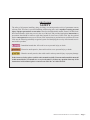
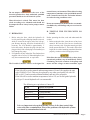
PT &
PTS Series
Scissor Lifts
Installation,
Operation and
Service Manual
Model Number ___________________
Serial # _________________________
Date placed in service _____________
IMPORTANT: READ CAREFULLY
BEFORE INSTALLING OR OPERATING LIFT
Part orders are subject to a $50 minimum charge.
September 2015
This manual was current at the time of printing. To obtain the latest, most updated version, please contact Presto
Lifts Customer Service Department or go to our website: www.PrestoLifts.com -- you will find a complete list of
current owner’s manuals to print.
Page 2 — PRESTO OWNER’S MANUAL: PT & PTS SERIES
CONTENTS
S E C T I O N 1:
INTRODUCTION...................................................................................................4
RESPONSIBILITY OF OWNERS AND USERS...................................................5
SAFETY ALERT SYMBOLS AND SIGNAL WORDS.........................................6
S E C T I O N 2:
SAFETY...................................................................................................................7
S E C T I O N 3:
INSTALLATION.....................................................................................................8
A. Installing..............................................................................................................8
B. Electrical..............................................................................................................8
C. Hydraulic.............................................................................................................9
D. Testing the Tilter with No Load..........................................................................9
S E C T I O N 4:
OPERATION.........................................................................................................10
A. Method of Operation.........................................................................................10
B. Operation Procedures.......................................................................................11
S E C T I O N 5:
MAINTENANCE.................................................................................................. 11
A. Routine Maintenance.......................................................................................11
B. Troubleshooting Maintenance..........................................................................12
S E C T I O N 6:
SERVICE...............................................................................................................13
A. Replacing Cylinder Seals..................................................................................13
B. Replacing Rigid & Swivel Wheels....................................................................13
C. Ordering Replacement Parts..............................................................................14
LIST OF FIGURES:
Figure 1 Loading and Operational Diagram.....................................................................10
Figure 2 Pinch Point Diagram..........................................................................................10
Figure 3 Wiring Diagram 12V DC....................................................................................15
Figure 4 Hydraulic Schematic......................................................................................... 15
Figure 5 Component Identification - DC Units................................................................16.
RESTOCKING POLICY...................................................................................................17
RETURN GOODS AUTHORIZATION (RMA) PROCEDURES....................................18
ORDERING REPLACEMENT PARTS............................................................................19
WARRANTY.....................................................................................................................20
PRESTO OWNER’S MANUAL: PT & PTS SERIES —
Page 3
SECTION 1
INTRODUCTION
The PT & PTS Series Container Tilters are designed for lifting, tilting and positioning a wide variety of loads.
Each tilter has front, rigid wheels and large rear swivel casters, allowing the tilter to be easily positioned under the
container to be tilted. A floor lock is provided for maintaining the tilter in position during loading and unloading.
This manual provides all the information for the safe and proper installation, operation and maintenance of Presto
Lifts PT & PTS Series Portable Container Tilters. It is important that this manual be read by all personnel involved
with the installation, maintenance or operation of the tilter. WHERE UNIQUE SITUATIONS ARISE, WHICH
ARE NOT COVERED IN THIS MANUAL, CALL PRESTO LIFTS, INC. FOR FURTHER INSTRUCTIONS.
Additional manuals are available upon request.
The Container Tilter has a nameplate, which provides the load capacity rating, serial number and model identification. Please refer to these numbers when ordering parts or requesting further information.
The PT & PTS Series Container Tilter is designed for in-plant, non-hazardous location use only.
Page 4 — PRESTO OWNER’S MANUAL: PT & PTS SERIES
Responsibility of Owners and Users
Inspection and Maintenance
The device shall be inspected and maintained in proper working order in accordance with Presto’s
owner’s manual.
Removal from Service
Any device not in safe operating condition such as, but not limited to, excessive leakage, missing
rollers, pins, or fasteners, any bent or cracked structural members, cut or frayed electric, hydraulic,
or pneumatic lines, damaged or malfunctioning controls or safety devices, etc. shall be removed from
service until it is repaired to the original manufacturer’s standards.
Repairs
All repairs shall be made by qualified personnel in conformance with Presto’s instructions.
Operators
Only trained personnel and authorized personnel shall be permitted to operate PowerStak.
Before Operation
Before using the device, the operator shall have:
• Read and/or had explained, and understood, the manufacturer’s operating instructions and safety
rules.
• Inspected the device for proper operation and condition. Any suspect item shall be carefully examined and a determination made by a qualified person as to whether it constitutes a hazard. All
items not in conformance with Presto’s specification shall be corrected before further use of the
PowerStak.
During Operation
The device shall only be used in accordance with this owner’s manual.
• Do not overload.
• Ensure that all safety devices are operational and in place.
Modifications or Alterations
Modifications or alterations to any Presto industrial positioning equipment shall be made only with
written permission from Presto.
PRESTO OWNER’S MANUAL: PT & PTS SERIES —
Page 5
SAFETY ALERT SYMBOLS AND SIGNAL WORDS
The safety of all persons operating, maintaining, repairing, or in the vicinity of this equipment is of paramount
concern. This is a powerful machine with moving parts, and is capable of causing personal injury if proper precautions are not taken. Therefore, throughout this manual, certain hazards have been identified which may occur in
the use of the machine, and there are appropriate instructions or precautions which should be taken to avoid these
hazards. In some cases, there are consequences which may occur if instructions or precautions are not followed.
Below are the symbols and signal words along with their definitions referenced from ANSI Z535.4 - Product Safety
Signs and Labels.
Safety Alert Symbols
These are the safety alert symbols.. They are used to alert you to potential physical injury hazards. Obey all safety messages that follow this symbol to avoid possible injury or death.
For use with DANGER signal word
(Red Background)
For use with WARNING signal word
(Orange Background)
For use with CAUTION signal word
(Yellow Background)
Signal Words
The meaning of different signal words as defined by ANSI Standard Z535.4 indicates the relative
seriousness of the hazardous situation.
DANGER indicates a hazardous situation which, if not avoided,
will result in death or serious injury.
(Red Background)
WARNING indicates a hazardous situation which, if not avoided,
could result in death or serious injury.
(Orange Background)
(Yellow Background)
CAUTION, used with the safety alert symbol, indicates a hazardous situation which, if not avoided, could result in minor or
moderate injury.
NOTICE is used to address practices not related to personal
injury.
(Blue Background)
SAFETY
INSTRUCTIONS
SAFETY INSTRUCTIONS (or equivalent) signs indicate safetyrelated instructions or procedures.
(Green Background)
Page 6 — PRESTO OWNER’S MANUAL: PT & PTS SERIES
SECTION 2
SAFETY
The safety of all persons installing, using, servicing, or working near the unit is of paramount concern
to Presto Lifts. The tilter is a powerful machine with moving parts, and is capable of causing personal
injury if proper precautions are not taken. Therefore, throughout this manual, Presto Lifts has identified certain hazards, which may occur in the use of the unit, and provided appropriate instructions or
precautions that should be taken to avoid these hazards. In some cases, Presto Lifts’ has also pointed
out the consequences that may occur if Presto Lifts’ instructions or precautions are not followed. Presto
Lifts uses the following nationally recognized system for identifying the severity of the hazards associated with its products:
DANGER – Immediate hazard that will result in severe personal injury or death.
WARNING – Hazard or unsafe practice, that could result in severe personal injury or death.
CAUTION – Hazard or unsafe practice, that could result in minor personal injury or property damage.
In the interest of safety, please read the entire manual carefully. You must understand the material
in this manual before you install, use, or service the unit. If you have any question about any of the
instructions in this manual, please contact Presto Lifts Inc. at 1-800-343-9322.
PRESTO OWNER’S MANUAL: PT & PTS SERIES —
Page 7
WARNING!
• Do not perform any repair work on tilters with
the forks in a raised position.
• All personnel must stand clear of the tilter when
container is being tilted.
• Do not put hand or feet under the forks or
the container while lowering or raising the
tilter.
• Do not work under the forks or under the container positioned on the forks.
• Do not stand, sit or climb on the forks of the
tilter, either during or after operation.
• Do not roll the tilter on soft, uneven or unstable
surfaces with a load.
• Do not exceed load capacity.
• Do not try to raise or lower the tilter while
moving the tilter.
Place load in center of the forks and against the tilter
platform. Be sure that the load is secures properly.
SECTION 3
INSTALLATION
Upon receipt of the Portable Container Tilters, inspect
the equipment completely to determine if there is any
shipment damage and that the tilter is complete. Do not
use the tilter if there appears to be any damage. With
the tilter in a collapsed position or the forks in a down
position, check the following by carefully removing the
battery housing cover and the shield that protects the
top of the power pack area.
1. Check for signs of damage, especially to the electrical and hydraulic components.
2. Check all connections for tightness. Also check for
visible hydraulic liquid around the connections.
3. Check for any physical damage to the frame or
wheels.
4. Inspect the forks for damage, either twisted or
bent.
CAUTION!
Do not operate the tilter before performing the installation procedures specified in section B, C, D and E.
Severe damage to the tilter may occur.
A.INSTALLING:
Read all of the instructions prior to starting or connecting the tilter.
Page 8 — PRESTO OWNER’S MANUAL: PT & PTS SERIES
1. Working Area
a) Make sure that the floor and the operation area
is flat, stable, relatively smooth and free from
dirt, obstacles and surface defects.
b) Move the empty tilter to exact operating area
ensuring that there are no change to obstacles
due to components or equipment in the general
area.
CAUTION!
Do not operate the unit out of doors or any place
where it could get wet. If any of the electrical components get wet, the worker may receive a shock.
The electrical components may also fail.
Make sure that all four (4) wheels of the tilter are in
contact with the floor.
WARNING!
If the unit is mounted in an unstable area it may tip
over when in use. To avoid this problem always use
the unit on a solid and stable surface.
B.ELECTRICAL:
1. DC Motor Models
a) Motors on the Portable container Tilters are
special, intermittent duty motors with high pull
up torques. These motors require heavier duty
controls than standard motors. A DC/ 1HP motor powers the standard PT & PTS units. The
battery source is 12 volt 60 AMP gel cell battery for the 2,000 lb. tilter, and a 72 AMP gel
cell battery for the 4,000 lb. tilter. Schematics
are provided at the end of this manual for the
connections of the dc operated tilters.
b) The tilters with the DC motors are shipped with
the positive terminal of the battery disconnected.
Connect the positive terminal being sure not to
touch any of the grounded parts while doing so
with the screwdriver or the wrench. (See figure
3 for electrical schematic.)
2. AC Motor Models
The optional motor available is a 115-volt AC motor,
which is a special, intermittent duty motor with high pull
up torques. These motors require heavier duty electrical
controls and outlets than standard motors.
CAUTION!
All wiring must conform to local codes and must be
performed by licensed electricians. The 1 horsepower
AC motor requires a 115 volt 20 AMP fused outlet.
WARNING!
Do not tamper with or remove the cover of the
electrical junction box. Only authorized, qualified
personnel should service the electrical system.
normal factory environments. Where below freezing
temperatures sometimes exist, special fluids must be
used. Contact Presto Lifts Inc. for further information when freezing conditions exists.
Motor direction is critical. This motor has been
wired according to its schematic and should not
be tampered with as it may lead to pump or motor
failure.
WARNING!
Do not use automotive hydraulic brake or transmission fluids, they will damage and pose a serious fire
hazard.
C. HYDRAULIC:
D.TESTING THE TILTER WITH NO
LOAD:
1. Before using the tilter, check the hydraulic oil
level by removing the solid plug from the reservoir,
which is located at the upper end of the left support. Remove the plug, check for oil and add oil if
necessary. The level should be approximately 1”
below the surface. Replace the plug with the vent
plug provided; if the vented plug is not installed you
may damage the pump.
2. Use hydraulic oil only in the tilter. The tilter has been
supplied with a Conoco 32. When adding fluid, use
only the recommended oils or equivalent.
CAUTION!
The Portable Container Tilters are designed for
Before operating the tilter, read and understand this
section.
1. Before testing the tilter, clear the area of any loose
material. Be sure the tilter has no obstructions
above it or on any side. Using the controls provided,
briefly operate the tilter (5-10 seconds). If the tilter
begins to rise with a humming sound and functions
properly, continue to the full upright position.
CAUTION!
If the tilter does not rise immediately, or there is any
operational problem, stop it immediately. Before
continuing, check the rotation of the pump and
motor and the voltage at motor terminals, again
If the lift will be used at normal ambient temperatures, Presto Lifts supplies the unit
with CONOCO 32 oil. This may be replaced by any other good quality oil with 150
SSU at 100° F and rust and oxidation inhibitors and anti-wear properties.
If the lift will be used at ambient temperatures below 0°F, use aircraft grade hydraulic
oil. Type 15 aircraft hydraulic oil is recommended.
The following are equivalent to Conoco 32
TYPE
MANUFACTURER
DTE 24
EXXON/MOBIL
NUTO H32
EXXON/MOBIL
AMOCO AW32 CHEVRON (AMOCOCO.)
AW32
CITGO
CAUTION
It is very important to keep the hydraulic oil free of dirt, dust, metal chips,
water, and other contamination. Most of the problems with hydraulic systems
are caused by contamination in the oil.
PRESTO OWNER’S MANUAL: PT & PTS SERIES —
Page 9
briefly operate the tilter. If the tilter does not move
smoothly with the humming sound, stop and review
the procedures in the section on troubleshooting.
FIGURE 1:
Loading and Operational Diagram
2. After raising the tilter completely, lower the tilter
completely. It should move slowly and smoothly
without a humming sound. If the tilter operates
properly, raise and lower the tilter and stop at different levels in order to familiarize yourself with
the tilter’s operations and movements.
WARNING!
As the container tilter platform and forks move up
and down, pinch points are created at locations near
the base of the base of the frame. While operating
the tilter the operator should be standing behind
the tilter located near the battery and power pack
area, In that way, the operator’s arms, legs or clothing will not be caught in the moving parts. During
operations the operator should avoid the pinch point
areas, which are located on either side of the tilter.
See the diagram pointing out the particular pinch
points (figure 1).
SECTION 4
OPERATION
A. METHOD OF OPERATION:
All Portable Container Tilters are provided with a special hydraulic relief valve, which is factory preset to the
maximum safe capacity of the container tilter (see the
nameplate attached to the tilter). Activating and holding the up switch will energize the motor. The motor is
attached to a positive displacement pump, which draws
hydraulic fluid from the reservoir and transfers it under
pressure to the cylinder. This forces the piston forward
and the forks to rise in a ninety-degree arc. Releasing
the up button will stop the tilter. A check valve between the pump and piston holds the forks in position.
Depressing and holding the down button of the switch
will energize a solenoid, which allows the oil from the
cylinder to return to the reservoir through a preset flow
control. This allows the tilter to lower smoothly and at
a controlled speed.
CAUTION!
Do not maintain the up button on the switch energized if the tilter does not move or has not reached
its upper limit. This may cause damage to the motor,
pump and controls.
Page 10 — PRESTO OWNER’S MANUAL: PT & PTS SERIES
FIGURE 2: Pinch Point
B. OPERATION PROCEDURES:
In order to operate the tilter, follow these operating
procedures:
1. Read and understand all the instructions before operating, if the tilter has modifications or accessories,
read and understand their functions.
2. Load the tilter correctly (figure 1.) Refer to the attached nameplate for load capacity information.
a) Do not load the tilter while it is running.
b) Do not exceed the maximum rated load (note
that load capacity is on the nameplate of the
tilter).
c) Engage floor lock prior to loading tilter.
d) Place load in the center and at the very back of
the forks.
e) If the load is unstable or may become unstable,
fasten it into position.
3. Operate the Tilter
a) To raise the tilter, press and hold the up button
on the switch.
b) To lower the tilter, press the down button on
switch.
c) Release the button to stop the tilter in either
direction.
4. Wait until the tilter has come to a complete stop before
loading or unloading.
5. Stand clear of the tilter when operating in order to
avoid injury.
WARNING!
a) Do not stand, sit or climb onto the tilter.
b) Do not load or unload a moving tilter.
c) If the tilter fails to move or exhibits strange movements or sounds, stop immediately. Do not operate
the tilter until it has been checked and repaired.
d) Obey all warning labels.
6. Moving the unit
a) When moving an empty tilter be sure the forks
are in a completely lowered position.
i) Release the floor lock.
ii) Set your push handle into position (see figure
1). The figure shows the handle in its raised
and lowered position. The handle is controlled
by a stop pin to prohibit travel beyond a safe
pushing point.
iii) With the handle in an up position, the tilter
can now be carefully moved forward. When
pulling the unit keep your feet clear of the
caster wheels.
b) When moving a loaded tilter, procedures are as
follows: lower the tilter forks until the container
legs or base is _” inch to 1” inch above the ground,
then proceed as previously discussed with an
empty tilter.
WARNING!
Do not move the unit with the fork in a raised position. Moving a raised container could cause product
to fall out or cause the basket or container to become
unstable, and thereby, could cause injury.
As you move the unit in a backward direction, keep
your feet clear of the swivel casters. When moving a
loaded tilter it would be safer for two (2) operators
to direct the tilter.
SECTION 5
MAINTENANCE
Generally, the Portable Container Tilter Lift will require
little maintenance. However, routine inspection and
maintenance will minimize costly repairs or hazardous
conditions.
WARNING!
Before servicing the unit, read and understand this
entire section and the section entitled Operating
Instructions.
Never go under or service a tilter with a load on the
forks or with the forks in a raised position. Always
service the tilter in a down position.
A. ROUTINE MAINTENANCE:
1.
All routine inspection maintenance should be
performed monthly, and can be performed on the
Portable Container Tilter Lift in a down position.
Before performing any maintenance, shut the power
off. In the case of the 115-volt, remove the plug from
the receptacle. When servicing a battery-operated
unit, disconnect the positive terminal from the battery. Remove the safety shelf cover and the battery
cover from the tilter. By doing this you will make
available all of the components that may require
servicing.
2. Periodic maintenance checks and service:
PRESTO OWNER’S MANUAL: PT & PTS SERIES —
Page 11
a) Check the oil level and add oil if necessary
according to the instructions on the hydraulic
schematic.
b) Check the snap rings on the pivot bar that
holds the tilt forks in place, if damaged, replace
them.
c) Check hydraulic lines for damage or leaking.
Replace if damaged.
d) Check for oil spots or leaks around fittings.
Trace leaks to the proper fitting and tighten.
e) Check wiring for damage. Replace immediately
if any signs of wear are evident.
f) Bearings on all tilters are permanently lubricated and require no servicing. (Do not oil or
grease.)
g) The rear swivel casters should be inspected for
lubricant wear or cracks. Replace if required.
Grease if needed.
h) Front load wheels should also be inspected for
wear or cracks. Replace if damage.
3. Charging a gel cell battery:
a) Lower lift to its full lowered position.
b) Remove battery cove, shield, positive and negative terminals.
c) Do not attempt to remove battery caps or covers.
d) Connect battery charger positive and negative
terminal to battery with charger provided with
lift.
e) Plug battery charger in 120-volt wall outlet.
f) Observe charger voltage meter. Low batteries
will show 14+ volts. As batteries charge the
voltage will drop to 12-13 volts.
g) Time to charge will depend on battery use.
Generally a one-shift operation will require 4-6
hours to recharge fully.
CAUTION!
a. Do not attempt to remove battery covers or
caps.
b. Wear safety glasses and gloves when charging or
replacing batteries.
c. Always use charger provided.
d. Read charger instruction prior to charging batteries.
WARNING!
The unit using a power supply of the 115-volt AC
must be disconnected from its power source. Do not
work on electrical circuits unless you are a qualified
electrician. DC units must have the positive cable
Page 12 — PRESTO OWNER’S MANUAL: PT & PTS SERIES
removed from the battery terminal. Do not move the
unit while maintenance is continuing to be done.
Before performing any maintenance on the unit, it
must be in a fully lowered position. Do not remove
hydraulic lines unless the tilter has been lowered
to its lowest down position. This should be verified
several times by pushing the down button on the
switch (prior to electrical disconnect).
When removing hydraulic hoses, crack the fittings
slowly to be sure that any hydraulic pressure that
may be residual is released.
B.TROUBLESHOOTING MAINTENANCE:
All servicing should be done by qualified personnel who
should have read and understood all of the information
provided in the Operating, Installation and Maintenance
sections in this manual.
1. Tilt will not move up
a) For the 115 volt AC units:
i) Load is too heavy. Check weight versus
nameplate rating.
ii) Check the power switch, fuses and overload
associated with its electrical circuits.
iii) Check voltage at motor; motor may have
failed.
b) For DC units:
i) Inspect battery voltage level for charge and recharge if necessary.
ii) Check terminals at the battery for corrosion or faulty connections.
iii) Check voltage at the motor; motor may have failed.
2. Operational noises (tilter is not moving or is very
noisy when moving):
a) Tilter may be overloaded or jammed. Check
load weights and obstructions.
b) For 115 volt AC motor, check voltage at terminal. Repair or replace.
c) Oil shortage, reservoir low or oil line failure.
Repair or replace.
d) Down valve open, check wiring. Replace if
necessary.
e) Air in the system causing cavitations. Check
fittings and lines.
3. Motor overheats:
a) Excessive cycling (15 cycles per hour maximum). Check actual time in use.
b) Low voltage-check voltage of AC motor.
c) Oil starvation – check filter on the pump by
removing the coil stem from the pump. Note:
Do not over tighten the stem when reinstalling
(maximum 4 ft/lb).
4. Tilter operating slowly:
a) Up cycle:
i) Oil starvation- check filter in reservoir.
ii) Oil viscosity- oil is too heavy or too thin.
iii) Air in cylinder- cycle tilter with no load 2-3 times and hold down the up button for 10
seconds after bottoming out on each cycle.
b) Down Cycle:
i) Down valve dirty - remove and clean.
Check oil condistion; replace if dirty. Note: Do not
over-tighten the stem when reinstalling (maximum
4ft/lbs.).
ii) Pinched hydraulic lines.
iii) Oil viscosity is too heavy.
5. Tilter raises, then fully lowers without power:
a) Down valve filter is dirty. Remove and clean.
Note: Do not over torque when reinstalling
down valve (maximum 4 ft./lbs).
b) Leaking hydraulic lines or fittings (check for
telltale oil spots and tighten).
c) Check valve in pump, may not be seating properly. Pump must be replaced.
6. Tilter will not lower when energized:
a) Down solenoid faulty. Check voltage of coil.
Check continuity of coil (could be burnt out)
b) Down solenoid retainer nut over torque causing
damage to the down valve stem. Replace.
c) Down valve dirty. Remove and clean.
d) Leaking hydraulic lines or fittings (check for
telltale oil spots).
e) Check valve in pump -- may not be seating.
Requires new pump.
SECTION 6
SERVICE
A. REPLACING CYLINDER SEALS:
1. Lower the tilter to its lowest position and hold down
switch for an additional 10 to 20 seconds.
2. Remove the steel plate and battery cover.
3. Disconnect the electrical power:
a) 115-volt units must have the plug removed from
the receptacle.
b) On DC units, remove the positive terminal from
the battery.
4. Disconnect the hydraulic hose from the cylinder and acp the line to prevent hydraulic fluid loss.
5. Remove the cylinder pin. Note: loosen the set
screws from the holding pin that has secured the cylinder in position.
6. Lift cylinder out of tilter.
CAUTION!
When disconnecting the hydraulic hose from the
cylinder, crack the fittings to be sure that the residual
hydraulic fluid pressure that may be in the line is
released slowly. Hold the cylinder securely while
removing the pin to prevent it from falling to the
floor or injuring someone that is servicing it.
7. Clamp cylinder securely at the base end.
8. Completely collapse cylinder piston.
9. Push gland into the cylinder 1/8".
10. Remove retainer ring.
11. Remove piston rod, piston and gland from cylinder.
12. Remove rod nut, piston and gland.
13. Remove and replace seals and wipers.
14. Assemble piston and gland to piston rod.
15. Assemble rod nut to piston rod & torque to 100 ft./lb.
16.
17.
18.
19.
20.
21.
Lubricate piston and seals and install in cylinder.
Insert retainer ring.
Install cylinder and hydraulic lines.
Fill reservoir.
Cycle tilter 2 to 3 times with no load.
Recheck reservoir oil level and fill if necessary.
B. REPLACING FRONT RIGID LOAD
WHEELS AND SWIVEL CASTER
WHEELS:
With the tilter in its completely lowered position, raise
the tilter one inch (1") using either a Johnson Bar or a
crow bar and chocking the unit to maintain the wheels
approximately 1/2" to 3/4" off the ground. Service one
wheel at a time.
1. Unloosening the screws that hold them in position,
remove the wheels and replace with new units. Note: the
nut and bolt assembly has a lock washer, it is imperitive
that the lock washer be replaced when reinstalling.
CAUTION!
Do not service more than one wheel at a time. Tilter
will become unstable if more than one wheel is serviced simultaneously.
PRESTO OWNER’S MANUAL: PT & PTS SERIES —
Page 13
C. ORDERING REPLACEMENT PARTS:
1. Standard replacement parts for each tilter are provided by part number and tilter models.
2. All key parts are identified and must be replaced with original equipment components.
3. Warranties will be voided where original equipment components are not used.
4. In ordering the replacement parts, be sure to include the serial number and model number of the tilter you are
requesting parts for.
STANDARD DC REPLACEMENT PARTS
Part #
Description
Used on
1026-028
Hydraulic Cylinder
All Units
1000-102-01
Oldham Coupling
All Units
1026-064
Cylinder Seal Kit
All Units
C141E
Battery, Gel Cell
All Units
B249G
Battery Charger
All Units
1026-046VR
Ground Cable
All Units
80000786VR
Hand Pendant Assy
All Units
B262RC
Motor Solenoid 12V
All Units
1000-056-03
Down Solenoid 12VDC
All Units
1000-076
Down valve stem
All Units
1000-034-10
Pump HyDry 1GPM w/dwn valve All Units
1000-046-01
Filter
All Units
B258CCW-1
Motor DC CCW
All Units
B211RC-A
Flow Control VLV
All Units
1026-037VR
Hydraulic Hose Hi-Pressure
All Units
1026-038VR
Hydraulic Hose Low-Pressure
All Units
1004-049VR
Wheel 8 x 2 Nylon w/swvl caster All Units
1003-001VR
Wheel 8 x 2 Nylon
All Units
1004-021AVR
Wheel 3 x 3 Nylon
PT Units
C102PH
Wheel s 5 x 2 Phenolic
PTS Units
C100
Floor Lock All Units
1026-042
Hand Control Magnet
All Units
STANDARD AC REPLACEMENT PARTS
Part #
Description
Used On
1026-028
Hydraulic Cylinder
All AC Units
1000-034CP
Oldham Coupling All AC Units
1000-056-01
Down Solenoid
115 secondary control voltage
1000-056-02
Down Solenoid
24V AC secondary control voltage
1000-076
Down Valve Stem
All Units
1000-034-10
Pump with Down Valve
All AC Units
E255R
Motor (1 HP)
All AC Units
80000263
Hand Pendant Assy
All AC Units
E308-E36
Foot Control
Optional
B211RC-A
Flow Control Valve
All Units
Page 14 — PRESTO OWNER’S MANUAL: PT & PTS SERIES
FIGURE 3: Wiring Driagram 12V DC
FIGURE 4: Hydraulic Schematic
PRESTO OWNER’S MANUAL: PT & PTS SERIES —
Page 15
FIGURE 5: Component Identification - DC Units
80000786VR
B249G
On Board Charger
B249H
Page 16 — PRESTO OWNER’S MANUAL: PT & PTS SERIES
PARTS
Standard parts may be returned with a 20% restocking fee. Modified or customengineered parts are not returnable. Unfortunately, due to potentially concealed
damage, all sales of electrical assemblies are final.
QUALITY ISSUES
Should you feel there is a quality problem, please contact the seller to ask questions and gather information on how to rectify the issue. Presto Lift Inc. reserves
the right to determine potential credits, as a result of factory defects, based on its
inspection of the merchandise.
GENERAL
All products shipped from our factory have passed Quality Assurance inspection and
testing. The carrier of choice has signed for, and accepted the product in new working
condition. The customer should inspect to ensure it is not received damaged, has no
concealed damage or is not incomplete. Parts orders are determined to be complete
based upon Presto Lift, Inc. inspection sheets and carrier shipping weights.
PRESTO OWNER’S MANUAL: PT & PTS SERIES —
Page 17
RETURN GOODS AUTHORIZATION POLICY
Presto Lifts provides the Return Goods Authorization (RGA) Policy, for specific models, as a
courtesy to our distributors in the event they do not receive what they ordered. If a customer
wishes to return a Presto Lifts product, please contact the Customer Service Department and
request an RGA number. This request must be made on or before the fifteenth calendar day
following the date of Presto Lifts’ invoice for the merchandise. Not all units are returnable.
Quantity orders and special designs cannot be returned under any circumstances. Presto Customer Service reserves the right for final judgment on all product returns.
The RGA number must appear on the outside of any packaging material for a return to be accepted and processed by Presto Lifts. Customers shipping returns from the Continental US,
Canada, or Mexico have thirty (30) days from date of RGA issue to have the product arrive at
Presto Lifts’ facility. All merchandise must arrive Free on Board at Presto Lifts’ facility or the
shipment will be refused and returned to the sender. All credits are issued less restocking and
refurbishing charges, regardless if the merchandise was damaged in transit.
Return addresses: please refer to your RMA for the address to which your product should be
returned.
Presto Lift Inc.
715 Highway 77
Manila, Arkansas 72442
Telephone: 800-343-9322
Fax: 888-788-6496
Page 18 — PRESTO OWNER’S MANUAL: PT & PTS SERIES
Ordering Replacement Parts
Presto Lifts has carefully chosen the components in your unit to be the best available for the purpose. Replacement
parts should be identical to the original equipment. Presto Lifts will not be responsible for equipment failures
resulting from the use of incorrect replacement parts or from unauthorized modifications to the unit.
Presto Lifts can supply all replacement parts for your lift. With your order, please include the model number
and the serial number of the unit. You can find these numbers on the name plate. This plate is located within
the scissors mechanism.
To order replacement parts, please call the Presto Parts Department. Parts are shipped subject to the following
terms:
• FOB factory
• Returns only with the approval of our parts department.
• Credit cards preferred (except parts covered by warranty).
• Freight collect for truck (except parts covered by warranty).
• Freight – prepaid and invoice for small parcel shipments (except parts covered by warranty).
• The warranty for repair parts is 30 days from date of shipment.
Parts replaced under warranty are on a “charge-credit” basis. We will invoice you when we ship the replacement
part, then credit you when you return the worn or damaged part, and we verify that it is covered by our warranty.
Labor is not covered under warranty for Parts orders.
Presto Parts Department
50 Commerce Way
Norton, MA 02766
Telephone: 800-343-9322
FAX: 888-788-6496
Email: [email protected]
www.PrestoLifts.com
PRESTO OWNER’S MANUAL: PT & PTS SERIES —
Page 19
Presto Lifts Limited Warranty Policy
Presto Lifts warrants all of its products against defects in the welded structural frame and, if applicable, scissor legs from faulty material and workmanship for a period of five (5) years from
the date of invoice.
All batteries and battery chargers have a limited warranty against defects in faulty material and
workmanship for a ninety (90) day period from the date of invoice through Presto Lifts.
All other components have a limited warranty against defects in faulty material and workmanship
for a two (2) year period from the date of invoice date of invoice and a 30 day limited warranty
on labor. Please note that prior authorization from Presto Lifts is required on all warranty work.
There are no implied warranties of any kind, more specifically, there are no warranties of merchantability or fitness for any particular purpose. Presto Lifts' sole warranty shall be as set forth
in this limited warranty.
Presto Lifts will elect to repair or replace a defective component without charge, if any components should become defective within the limited warranty period. Proof of purchase is required
for warranty. The charge for shipping the defective component is the responsibility of the buyer
and must be accompanied with an RMA number. The shipping charge to return the component to
the buyer is the responsibility of Presto Lifts, Inc.
This limited warranty does not cover labor expense for removal or reinstallation of components
after thirty days. This limited warranty shall not cover, among other things: damages resulting
from foreign matter or water, failure to provide reasonable and necessary maintenance, and if applicable, use of product while charger is plugged into an AC outlet, or failure to follow operating
instructions. The limited warranty is not valid for damage resulting from negligence, accident,
unreasonable use, abuse or misuse, exceeding data plate capacities or altering the product without
Presto Lifts authorization.
Presto Lifts expressly disclaims and excludes any liability for consequential, incidental, indirect
or punitive damages or financial loss to people or property resulting from any breach of warranty
or the operation or failure of this product.
Presto Lifts makes no representation that this product complies with local, state, or federal safety/
product standards codes. Should this product fail to comply in any way with those codes, it shall
not be considered a defect of materials or workmanship. Presto Lifts shall not be held liable for
any damages resulting from noncompliance. It is the dealer's responsibility to exercise this limited
warranty. This limited warranty is provided to the original purchaser (defined as the original end
user) and is nontransferable. This constitutes the complete and final agreement involving Presto
Lifts and limited warranty obligations for products.
Page 20 — PRESTO OWNER’S MANUAL: PT & PTS SERIES
MANY NEEDS REQUIRE MANY OPTIONS...
LET PRESTO MEET THOSE NEEDS!
Call Presto Sales
for stock or
customized lift inquiries:
800-343-9322
Email: [email protected]