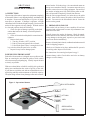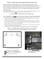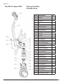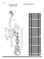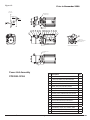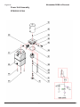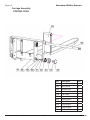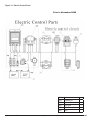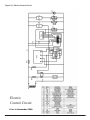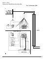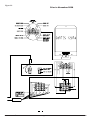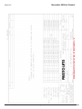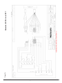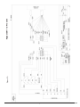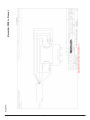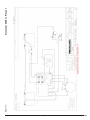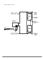
1
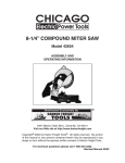
Power Stak
PPS2200-101AS
FOR UNITS SHIPPED PRIOR TO MARCH 2014
Installation, Operation
and Service Manual
Model Number _____________________________________
Serial # ____________________________________________
Date Placed in Service _____________
IMPORTANT: READ CAREFULLY
BEFORE INSTALLING OR OPERATING LIFT
Part orders are subject to a $50 minimum charge.
September 2015 REV
Presto Lifts Limited Power Stacker Warranty Policy
Presto Lifts warrants the Power Stacker against defects on the mast, fork carriage, chains, pumps,
DC motors, controllers, cylinders and wiring harnesses from faulty material and workmanship for a
period of one (1) year from the date of invoice.
All wear items such as batteries, wheels, motor brushes, seals, bearings, hydraulic hoses, all switches,
battery chargers and forks have a limited warranty against defects in faulty material and workmanship
for a ninety (90) day period from the date of invoice and 30 day limited warranty on labor. Please
note that prior authorization from Presto Lifts is required on all warranty work.
There are no implied warranties of any kind, more specifically; there are no warranties of merchantability or fitness for any particular purpose. Presto Lifts’ sole warranty shall be as set forth in this
limited warranty. Presto Lifts will elect to repair or replace a defective component without charge,
if any components should become defective within the limited warranty period. Proof of purchase is
required for warranty. The charge for shipping the defective component is the responsibility of the
buyer and must be accompanied with an RGA number. The shipping charge to return the component
to the buyer is the responsibility of Presto Lifts, Inc.
This limited warranty does not cover labor expense for removal or reinstallation of components
after thirty days. This limited warranty shall not cover, among other things: damages resulting
from foreign matter or water, failure to provide reasonable and necessary maintenance, and if
applicable, use of product while charger is plugged into an AC outlet, or failure to follow operating instructions. The limited warranty is not valid for damage resulting from negligence, accident,
unreasonable use, abuse or misuse, exceeding data plate capacities or altering the product without
Presto Lifts authorization.
Presto Lifts expressly disclaims and excludes any liability for consequential, incidental, indirect
or punitive damages or financial loss to people or property resulting from any breach of warranty or
the operation or failure of this product.
Presto Lifts makes no representation that this product complies with local, state, or federal safety/
product standards codes. Should this product fail to comply in any way with those codes, it shall
not be considered a defect of materials or workmanship. Presto Lifts shall not be held liable for any
damages resulting from noncompliance. It is the dealer’s responsibility to exercise this limited warranty. This limited warranty is provided to the original purchaser (defined as the original end user)
and is nontransferable. This constitutes the complete and final agreement involving Presto Lifts and
limited warranty obligations for products.
This manual was current at the time of printing. To obtain the latest, most updated version, please
contact the Customer Service Department or go to our website: www.PrestoLifts.com -- you will
find a complete list of current Owner’s Manuals to print.
PRESTO OWNER’S MANUAL
Page 2 POWER STAK PPS2200-101AS
LIST OF FIGURES:
TABLE OF CONTENTS
S E C T I O N 1:
Limited Warranty ...................................................................2
Introduction.............................................................................4
Responsibility of Owners and Users.......................................5
S E C T I O N 2:
Safety.................................................................................. 6-7
S E C T I O N 3:
Installation...............................................................................8
A. Inspection ........................................................................8
B. Removing from Pallet......................................................8
C. Preparation for Use...........................................................8
Wheel Traction & Straddle Leg Set-Up..................................9
S E C T I O N 4:
Operation...............................................................................10
A. Operating Instructions.....................................................10
Suggested Daily Operator Checklist.....................................11
B. Daily Operations Maintenance Checks...........................11
S E C T I O N 5:
Battery Maintenance.............................................................12
A. Preparing to Charge a Battery ........................................12
B Charging the battery........................................................12.
C. Warnings and Battery Info..............................................12
D. Battery maintenance........................................................12
E. Charger Operation...........................................................13
S E C T I O N 6:
Fig. 1: Operational Buttons............................................... 8
Fig. 2: PPS2200-101AS Exploded View
(Prior to Nov. 2008).................................................... 15
Fig. 3: PPS2200-101AS Exploded View
(Nov. 2008 to Present)................................................ 17
Fig. 4: PPS2200-101AS Inner Mast (Prior to Nov. 2008)..... 18
Fig. 5: PPS2200-101AS Inner Mast (Nov. 2008 to Present)..... 19
Fig. 6: Cylinder View (Prior to Nov. 2008)............................. 20
Fig. 7: Cylinder View (Nov. 2008 to Present)......................... 20
Fig. 8: Caster Wheel Assembly (Prior to Nov. 2008)............ 21
Fig. 9: Caster Wheel Assembly (Nov. 2008 to Present)......... 22
Fig. 10: Drive Wheel Assembly...................................... 23
Fig. 11: Control Pod........................................................ 24
Fig. 12: Steering Assembly (Prior to May 2007)................... 25
Fig. 13: Steering Assembly (Prior to May 2007 - Aug. 2008)... 26
Fig. 14: Steering Assembly (August 2008 to Present)............ 27
Fig. 15: Power Unit Assembly (Prior to Nov. 2008)............... 28
Fig. 16: Power Unit Assembly (Nov. 2008 to Present)........... 29
Fig. 17: Carriage Assembly ........................................... 30
Fig. 18: Labels & Precautionary Warnings..................... 31
Fig. 19: Electric Control Panel (Prior to Nov. 2008).............. 32
Fig. 20: Electric Control Circuit (Prior to Nov. 2008)............. 33
Fig. 21: Wiring (Prior to Nov. 2008)...................................... 34
Fig. 22: Wiring Diagram (Prior to Nov. 2008)........................ 35
Fig. 23: Wiring Diagrams (Nov. 2008 to Present).................. 36
Fig. 24: Wiring Diagrams (Nov. 2008 to July 2011)................ 37
Fig. 25: Wiring Diagrams (August 2011 to Present)............... 38
Fig. 26-31: Wiring Diagrams (Nov. 2008 to Present)........ 39-44
Fig. 32: Battery Connection............................................ 45
Maintenance..........................................................................13
A. Weekly Operations Maintenance Checks........................13
B. Monthly Operations Maintenance Checks .....................13
S E C T I O N 7:
Troubleshooting....................................................................14
ORDERING REPLACEMENT PARTS...............................46
RESTOCKING POLICY......................................................46
RETURN GOODS AUTHORIZATION...............................47
LIST OF TABLES:
Table 1: PPS2200-101AS Assembly
(November 2008 to Present)....................................... 16
PRESTO OWNER’S MANUAL
Page 3 POWER STAK PPS2200-101AS
SECTION 1
INTRODUCTION
This manual attempts to provide all of the information necessary for the safe and proper installation,
operation and maintenance of Presto Lifts Inc. battery operated, Power Stak. It is important that all
personnel involved with the installation, maintenance or operator of the stacker read this manual.
Additional manuals are available upon request or at www.PrestoLifts.com.
Each Presto stacker is equipped with nameplate, serial number and model identifications. Please
refer to these numbers when ordering parts or requesting further information.
The Presto stackers are designed for lifting, lowering and positioning a wide variety of loads.
WHERE UNIQUE SITUATIONS ARISE, WHICH ARE NOT COVERED IN THIS MANUAL,
CALL PRESTO LIFTS FOR FURTHER INSTRUCTIONS.
The battery operated stackers are designed for in-plant/non-hazardous locations only. They can be
used in a 8’ or larger aisle. These units are not for personnel lifting.
PRESTO OWNER’S MANUAL
Page 4 POWER STAK PPS2200-101AS
Responsibility of Owners and Users
Inspection and Maintenance
The device shall be inspected and maintained in proper working order in accordance with Presto’s
owner’s manual.
Removal from Service
Any device not in safe operating condition such as, but not limited to, excessive leakage, missing
rollers, pins, or fasteners, any bent or cracked structural members, cut or frayed electric, hydraulic,
or pneumatic lines, damaged or malfunctioning controls or safety devices, etc. shall be removed from
service until it is repaired to the original manufacturer’s standards.
Repairs
All repairs shall be made by qualified personnel in conformance with Presto’s instructions.
Operators
Only trained personnel and authorized personnel shall be permitted to operate PowerStak.
Before Operation
Before using the device, the operator shall have:
• Read and/or had explained, and understood, the manufacturer’s operating instructions and safety
rules.
• Inspected the device for proper operation and condition. Any suspect item shall be carefully examined and a determination made by a qualified person as to whether it constitutes a hazard. All
items not in conformance with Presto’s specification shall be corrected before further use of the
PowerStak.
During Operation
The device shall only be used in accordance with this owner’s manual.
• Do not overload.
• Ensure that all safety devices are operational and in place.
Modifications or Alterations
Modifications or alterations to any Presto industrial positioning equipment shall be made only with
written permission from Presto.
PRESTO OWNER’S MANUAL
Page 5 POWER STAK PPS2200-101AS
SECTION 2
SAFETY
You must be trained and certified to operate this powered stacker. Federal law states that only properly
trained operators are permitted to operate a powered industrial stacker and that your employer must
train you and certify that you are qualified. (OSHA 1910.178 29QFR-7-1-06 Edition)
Presto lifts does not offer operator training. Operator training programs may be offered by your local Presto Lifts dealer or obtained online. Enter, “powered industrial truck operator training” into a
search engine.
The battery operated stackers are very powerful lifts capable of doing large amounts of work.
DO NOT OPERATE THESE LIFTS WITHOUT CAREFULLY READING THIS MANUAL. In order to provide for the safe
operation of these stackers, Presto Lifts Inc. has identified certain hazards that may occur during the maintenance and use of
these lifts. For safety reasons these units are designed to be serviced or repaired in the fully lowered position. If performed
properly, this will greatly reduce the possibility of injury.
SAFETY ALERT SYMBOLS AND SIGNAL WORDS
The safety of all persons operating, maintaining, repairing, or in the vicinity of this equipment is of paramount concern.
This is a powerful machine with moving parts, and is capable of causing personal injury if proper precautions are not taken.
Therefore, throughout this manual, certain hazards have been identified which may occur in the use of the machine, and
there are appropriate instructions or precautions which should be taken to avoid these hazards. In some cases, there are
consequences which may occur if instructions or precautions are not followed. Below are the symbols and signal words
along with their definitions referenced from ANSI Z535.4 - Product Safety Signs and Labels.
Safety Alert Symbols
These are the safety alert symbols.. They are used to alert you to potential physical injury hazards. Obey all safety messages that follow this symbol to avoid possible injury or death.
For use with DANGER signal word
(Red Background)
For use with WARNING signal word
(Orange Background)
For use with CAUTION signal word
(Yellow Background)
Signal Words
The meaning of different signal words as defined by ANSI Standard Z535.4 indicates the relative
seriousness of the hazardous situation.
DANGER indicates a hazardous situation which, if not avoided,
will result in death or serious injury.
(Red Background)
WARNING indicates a hazardous situation which, if not avoided,
could result in death or serious injury.
(Orange Background)
(Yellow Background)
CAUTION, used with the safety alert symbol, indicates a hazardous situation which, if not avoided, could result in minor or
moderate injury.
NOTICE is used to address practices not related to personal
injury.
(Blue Background)
SAFETY
INSTRUCTIONS
SAFETY INSTRUCTIONS (or equivalent) signs indicate safetyrelated instructions or procedures.
(Green Background)
PRESTO OWNER’S MANUAL
Page 6 POWER STAK PPS2200-101AS
between the stacker and a fixed object will be crushed
or even cut off.
• If traveling forks first, keep both hands on the control
handle and be careful when changing direction of
travel. Keep your feet clear of the stacker.
• Keep the stacker under control at all times. Operate at
a speed that allows you to stop safely. Be even more
careful on slippery or uneven surfaces. Do not run over
objects on the floor.
• Perform all stacker movements smoothly and at a
speed that will give you time to react if an emergency
occurs.
WARNING!
When servicing the unit:
1. Key should be in “OFF” position.
2. E-stop should be depressed.
3. Disconnect the batteries at the terminals.
• Do not perform any repair work on lifts if there is a
load on the forks or platform.
• Do not perform any repair work if the forks or platform
is in the raised position.
• All personnel must stand clear of the lift while in motion.
• Do not put hands or feet under the forks or platform.
• Do not stand underneath the forks or platform.
• Do not stand in front of the stacker while in motion.
• Do not stand, sit or climb on the lift.
• Do not use the lift on soft, uneven or unstable surfaces.
• Do not exceed the load center or capacity.
WARNING!
You or others around you can be seriously injured or even
killed if you don’t use this stacker correctly. Read and
obey all warnings and instructions in this manual and on
the stacker. It is your responsibility before starting work
to make sure it is in good working order.
Always be alert to the area around you and watch where
you are walking. Be careful that you don’t get pinned or
crushed between the stacker and a fixed object such as a
wall or post.
• Watch your hands and feet. A foot or hand caught
PRESTO OWNER’S MANUAL
Tipovers and falls are very serious accidents; you can be
crushed or even killed. To prevent injury, know where you are
at all times and follow the rules of safe stacker operation.
• Be careful when working around docks, dockboards
and trailers. Stay away from the edge of docks and
ramps. Check to make sure the wheels of truck or trailers are chocked.
• Travel with the load or forks close to the ground.
Watch for overhead obstructions. Perform all stacker
movements smoothly and at a speed that will give you
time to react in an emergency.
• Keep your hands and feet away from all moving parts
such as masts, chains, forks or wheels.
• Never stand on or under the forks, or allow anyone
else to stand on or under them. Never ride on the
stacker or allow anyone else to ride. There is no safe
place to sit or stand.
• Before you leave your stacker, be sure to lower the
forks to the floor. Shut the stacker off with the key.
WARNINGS
DO NOT use this stacker until you have been trained and
authorized to do so.
DO NOT operate until you have read all warnings and instructions.
DO NOT exceed load center or load weight capacities (check
capacity plate).
DO NOT operate until you have checked the conditions of
the stacker: lift systems, forks, chains, and cables.
DO NOT use if any part is damaged, worn or not working
properly.
DO NOT use on ramps or inclines. Only smooth level surfaces.
DO NOT use for lifting or carrying people.
DO NOT handle unbalanced, unstable or loosely stacked
loads.
DO NOT travel with forks or platform in an elevated position.
DO NOT handle tall, unsecured or unstable loads that could
fall.
DO NOT allow people to stand or pass under forks or platform with or without load.
DO NOT operate when parts of anyone’s body may be close
to mast structure or any moving parts.
DO NOT drop loads on platform or forks.
DO NOT alter or modify this stacker in any way.
Page 7 POWER STAK PPS2200-101AS
SECTION 3
INSTALLATION
A. INSPECTION:
Upon receipt of the stacker, inspect the equipment completely
to determine if there is any shipping damage, and that the lift
is complete. Presto tests and inspects every piece of equipment prior to shipment. If damage is apparent, a freight
claim must be filed with the freight company. Do not use the
stacker if there appears to be any damage. With the stacker
in a lowered position, check the following:
• Check for signs of damage especially to the back
cabinet that houses the battery, electrical/hydraulic
power pack.
• Check all electrical and hydraulic connections for
tightness.
• Remove back panel.
1. Turn key switch to “OFF” position.
2. Push in E-stop and unscrew the red knob,
3. Lift off back panel. There is enough wire to the
key switch to allow the panel to be set aside.
• Inspect for any bent or damaged parts.
tion of stacker. Pick the unit up. On conventional masts use
the top cross member of the lift. On narrow masts the cover
must be removed to access lifting equipment. Be careful of
the stacker swinging once fully lifted off the pallet or skid.
Have all personnel completely cleared from the area.
Pick the unit up approximately six inches above the pallet
or skid. Once raised, remove the pallet or skid from below
the lift. Do not move the lift around in the air. Lower the
stacker on the ground.
C. PREPARATION FOR USE
This stacker left our factory in new condition. It has been
inspected and weight tested to assure all performance standards have been met.
Visually inspect the stacker for damage. Check for attachments and accessories that may have been ordered. If there
is any damage or missing parts, report it to your carrier and
your Presto dealer immediately.
Remove all metal/plastic bands, cardboard and other material
used for shipping purposes.
Check to see if chains are in place, and that the lift system is
in working order. Inspect for oil leaks.
See instructions for removing back panel on pg. 5.
B. REMOVING FROM PALLET
Each of the Presto stackers is shipped out on a pallet or skid.
Prior to removing the unit from the pallet or skid, remove
all tie down straps and packaging. Visually inspect the unit
as closely as possible.
Connect battery cable. Check cables and wires on battery
charger as well as battery.
With an overhead hoist or forklift, carefully pick up the unit
taking into consideration the center of gravity of the unit.
If you choose to pick the unit with an overhead hoist, use a
nylon sling and hoist with a minimum of 2,000-lb. capacity.
The nylon sling will not do any damage to the steel construc-
Figure 1: Operational buttons
BELLY BUTTON SWITCH
LIFT UP
LIFT DOWN
HORN
SPEED CONTROL
DIRECTION CONTROL
PRESTO OWNER’S MANUAL
Page 8 POWER STAK PPS2200-101AS
CRITICAL PROCEDURE FOR PROPER WHEEL TRACTION
Proper Drive Wheel traction is obtained for the PowerStak Straddle unit using this Procedure
All PowerStak Models are designed and intended to operate on an unfinished concrete floor surface. If any
PowerStak is operated on smooth or polished concrete, sealed concrete, epoxy sealed floor, linoleum or
other smooth surfaces Drive Wheel traction performance may be affected; If traction issues are encountered
Rubber Drive Wheels are available through special order. Please contact Customer Service at Presto
Lifts 1-800-343-9322
When any PowerStak is operated on a wet, oily, powdery, sandy or non-uniform liquid or granular surface
Drive Wheel traction performance will be affected and loss of traction will occur.
SET-UP PROCEDURE FOR POWERSTAK STRADDLE LEGS
NOTE: STRADDLE LEGS MUST BE ADJUSTED IN ACCORDANCE WITH THIS PROCEDURE
1. PowerStak unit located on flat, clean uniform surface, unloaded, forks raised a minimum of 1” off the floor
2. Determine the desired/required straddle width dimension (2 inches greater than pallet width, 1” on each side of
the pallet or load, up to a maximum of 50 inches inside width)
3. Be sure to fully loosen all bolts before moving stabilizing legs. Adjust one stabilizer leg at a time – using a pry
bar, pinch bar, rubber mallet etc. move the straddle leg out from the base tube to the desired position. Do not
move too far, see picture below, if the ¼” wide painted White Line is visible the leg is pulled out too far; Maximum movement 5 ½” for each leg for 2200 pound units.
4. Adjust second Straddle Leg – using a pry bar, pinch bar, rubber mallet etc. move the straddle leg out from inside
the base tube to the desired straddle width position.
5. Straddle Legs must be symmetrically adjusted, both legs adjusted to the same extended dimension!
CRITICAL – STRADDLE BOLT TIGHTENING SEQUENCE & PROCEDURE
Set up procedure for PowerStak Straddle legs with 3 or 4 Bolts:
5½"
Bolt
Bolt
Bolts
Back off all bolts and follow steps.
First - tighten Bolt 1 to 85 foot pounds.
Second - tighten Bolt(s) 2 to 85 foot pounds.
Third - tighten Bolt 3 to 25 foot pounds - NOT 85.
Last - securely tighten all lock nuts.
PRESTO OWNER’S MANUAL
Page 9 NOTE:
When adjusted correctly, white
line cannot be seen.
POWER STAK PPS2200-101AS
SECTION 4
parked, always put the handle in the full vertical position
with the brake applied and the forks in lowered position.
OPERATION
A. OPERATING INSTRUCTIONS:
To Raise and Lower:
There are two buttons located on both sides of the handle.
The inside one is for raising the forks. The outside one is for
lowering the forks. When operating, always make sure the
load being lifted is within the loading capacity of your stacker
and the load has been stacked safely on the pallet. Also, make
sure that the length of the forks corresponds to the length of
the pallet. In this way, the load rollers will place themselves
in the opening at the end of the pallet, so that when you
raise the forks, you will not break the bottom boards of the
pallet. Always make sure that when entering the pallet that
the forks are in the fully lowered position. Be careful when
lifting pallets that are too short or too long for the stacker.
It might destroy your pallet by breaking the bottom boards,
and if the forks project through the end of the pallet, the tips
of fork may go into the next pallet that is behind the pallet
that you are lifting, which may bend the tips of forks and
overload the capacity of the stacker.
To Travel:
To travel, rotate the butterfly controls throttle on the upper
part of the handle. When rotating the butterfly control CW
towards the forks, the stacker runs forwards in the forks first
direction. When rotating the butterfly CCW towards you, the
stacker runs backwards in the handle first direction. Always
make sure the stacker clears any obstruction when traveling, and that your path of travel is clear of people. Never
carry loads above the loading capacity of the stacker. It is
suggested that when traveling without a load, the forks be in
the lowered position. The speed of the stacker is increased
by the degree of the rotation in either direction; it functions
like a throttle. When you release your hand from the butterfly
control, it automatically will resume to the neutral position
and the speed of the stacker will slow down.
Reversing Safety:
At the end of the handle there is a large, red reversing bar
(belly button switch) that is designed to protect the operator
from injury. When the operator runs the stacker backwards,
and the end of the handle comes in contact with the operator’s body, the stacker will automatically reverse direction
and travel away from the operator. When the reversing safety
bar comes in contact with your body during operation, immediately release your hands from the butterfly control
and put the handle up to its vertical position or down to its
lowest position and the brake is on. The reversing safety bar
will automatically resume to its original position after being
activated.
Horn:
As standard equipment, a horn that is located on the top of
the handle.
AUTHORIZED OPERATORS SHOULD READ
AND UNDERSTAND ALL INSTRUCTIONS,
PRECAUTIONS AND WARNINGS.
IMPROPER USE OF THIS LIFT TRUCK COULD
RESULT IN INJURY AND/OR DAMAGE
TO LOAD AND EQUIPMENT.
To Brake:
Your stacker is equipped with a magnetic brake. The brake
is applied when the handle is in its vertical position between
10 – 15 degrees and lowered position between 80 – 90 degrees. The brake could be released when you pull down the
handle at any point between 15 – 80 degrees. Always make
sure the brake is released before operating the stacker. When
the stacker is running, you could brake the stacker by raising
the handle to its vertical position or lowering the handle to
its lowest position. Or, to turn the butterfly controls in the
opposite direction, the change in direction of the motor will
slow down, stop, and reverse the direction of stacker. When
PRESTO OWNER’S MANUAL
Page 10 POWER STAK PPS2200-101AS
DAILY OPERATOR CHECK LIST
CHARGE CONDITION/BATTERY CHECK LIST
1. Check Battery Discharge Indicator (Fuel Gage and Hour Meter) – Be sure unit is
showing proper Charge Level before operating unit
2. Check to be sure Charging Cord is Unplugged and properly stowed before operating unit
3. Inspect Battery Wire Connections – All connections should be tight with No Corrosion (white powder) showing at the Battery Terminals
4. Inspect Battery Case – There should be no cracks or visible damage to the Battery
Case
WALK AROUND INSPECTION
1. Check general condition of Stacker (loose or broken parts, oil, dangling wires, dents,
cracked covers etc.)
2. Check metal frame, mast, carriage and font load supports for cracked welds, worn or
flat rollers, loose or disconnected chains, loose pins, missing snap rings, and loose or
missing hardware – bolts, nuts washers etc.
3. Check for evidence of hydraulic leaks
4. Make sure all precautionary labeling is in place and legible
FUNCTIONAL INSPECTION
1.
2.
3.
4.
5.
Check Drive – Forward and Reverse Function
Check Lift – Up and Down Function
Check Function for Belly Button Reverse
Check Horn Function
Check Brake Function
OPERATOR IDDATE
DO NOT USE OR OPERATE STACKER IF ANY FUNCTION IS NOT
OPERATING PROPERLY OR IF STACKER APPEARS UNSAFE IN ANYWAY
REPORT CONCERNS TO SUPERVISOR IMMEDIATELY!
PRESTO OWNER’S MANUAL
Page 11 POWER STAK PPS2200-101AS
• Inspect the lift for damaged or worn parts. Do not use
if not in safe operating condition.
• Use lift on hard level surfaces only.
• Make sure load is evenly distributed, not loose or unstable, and is as far back on platform or forks as possible.
Do not pick up loads on tips or forks or edge of platform.
• For fork models, adjust forks to the maximum practical width. Pick up loads on both forks.
• Do not overload. Check load center and load weight
capacities on the nameplate.
• Make sure travel and work area is clear of obstructions.
• Check overhead clearance before lifting loads or transporting.
B. DAILY OPERATIONS
MAINTENANCE CHECKS:
1. Battery
A. Check for corroded and loose terminals. A
white powder substance will be present if there is
any existing corrosion.
B. Visually inspect for any cracks or damage to the
casing.
C. Check for loose battery tie-downs.
SECTION 5
BATTERY MAINTENANCE
A. PREPARING TO CHARGE A BATTERY
1. Always turn off E-stop and key switch before working
with the batteries.
2.
Be sure the area around the stacker and the battery is
well ventilated while battery is being charged.
3. The battery terminals, connections and wiring connections should be clean and free of corrosion. When cleaning any of these components wear a face shield or other
suitable protective eyewear.
B. BATTERY CHARGING
Charging must be performed with the charger that is provided
with or prewired into the machine. During charging, the
temperature in the battery must not exceed 120 F. Charging
simultaneously with truck operation is not recommended.
Plug the charger into a 115 volt outlet. Charge until the battery gauge indicator lights show fully charged (approximately
6-8 hours).
2.Charger
A. Inspect wire connections.
B. Check power cord for nicks/damage.
C. Check power charger for proper mounting.
3. Hydraulic System
D.
E.
F.
G.
Inspect pump and cylinder for oil leaks.
Check hydraulic oil level.
Check hydraulic fittings and hoses.
Check ram for nicks/damage.
C. WARNINGS AND BATTERY INFORMATION
Avoid use of open flame near batteries. At temperatures
around freezing point, battery capacity is reduced by 30%.
The battery terminals, connections and wiring should be
clean and free of corrosion. When cleaning any of these
components, wear a face shield or other suitable protective
eyewear. Read, understand, and follow all battery and battery
manufacturer’s specific precautions while working with and/
or charging batteries.
4. Frame Assembly
A. Check chain roller assembly connections.
B. Check for any worn or damaged parts.
D. BATTERY MAINTENANCE
To measure the voltage, use a digital voltmeter (DC) on the
battery poles. The truck must not have been in use for the
previous 30 minutes.
DANGER
Never alter the AC cord or plug provided. If it will not
fit outlet, have proper outlet installed by a qualified electrician. Improper connection can result in a risk of an
electric shock.
1. Disconnect the charger from the 115 volt wall outlet
once the indicators read fully charged.
VOLTAGE
Approx. 12.7 V...... Fully charged
Approx. 12.2 V......... 1/2 charged
Approx. 12.0 V......... 1/4 charged
Approx. 11.6 V......... Discharged
PRESTO OWNER’S MANUAL
Note: The batteries are designed for intermittent use.
Continual usage will wear the battery out and charging
will be required.
Page 12 POWER STAK PPS2200-101AS
E. CHARGER OPERATION
Power Lamp
1. Green: Connection correct. Charger will operate normally.
2. Red: Bad connection or bad battery.
Fault
1. Red light blinks 3 times in 5 seconds: The output between
charger is faulty, loose, or bad connection
2. Red light blinks 5 times in 5 seconds: The temperature
is too hot for the charger to operate.
3. Building power is not compatible; too low or too high.
+- 10% is the general rule.
Charge Lamp
1. Red: Charger can charge normally. The battery is less
than 70%
2. Orange: Battery is between 70% and 100% charged.
3. Green: Battery is at 100%. Fully charged.
4. No light: The charger can not charge the battery. Voltage
of the battery may be too low to cause the charger to start. It
must be at 9 volts to initiate charge.
SECTION 6
they are turning smoothly.
5. LIFT CHAINS: Check to see that they are in place and
not loose.
6. FORKS: Check that they are not bent or cracked.
7. BRAKES: Ensure brakes work properly.
8. CABLES; WIRES: Check that there are no loose cables
or wires.
9. LABELS: Ensure all precautionary labels and guards
are in place.
B. MONTHLY OPERATIONS
MAINTENANCE CHECKS:
1. Battery (maintenance free)
A. Clean terminals.
B. Clean battery compartment area if there are signs
of corrosion.
2. Hydraulic System
A. Clean and inspect hydraulic cylinder.
B. Lubricate chain with a rust inhibitive lubricant
(light machine oil).
C. Check chain tension. It should be even on both
chains. The chain should be tight enough so that
it does not come off of the roller assembly.
3. Frame Assembly
MAINTENANCE
Operation of Presto Power Stak is very simple — as is their
construction. They require very little maintenance. Reasonable care will result in excellent trouble-free performance.
The Power Stak is designed for one-man operation and ease
of performance.
• Grease floor wheels and casters at least once a month.
• Use only Hydraulic Oil AW32 or Dextron III in the
hydraulic system.
• Do not overload your lift.
• Check brakes, steering mechanisms and controls before each use.
A. Clean and lubricate all roller bearings, cam followers and all moving parts.
B. Clean and inspect all welds.
C. Check wheels for wear and damage.
D. Inspect nameplate for legibility. Place the serial
and model number shown on the nameplate on the
cover of the manual for future reference.
4.Electrical
A. Check batteries, motors, controllers, limit switches,
electrical conductors and connections.
CAUTION:
DO NOT USE LIFT IF IT IS NOT OPERATING
PROPERLY, OR APPEARS UNSAFE IN ANY WAY!
A. WEEKLY OPERATIONS
MAINTENANCE CHECKS:
1. DAMAGE: Check for bent, dented, worn or broken
parts.
2. LIFT SYSTEM: Check to assure that there is no binding or excessive play in the forks. Check for quiet and
smooth operation of the lift cylinder. Check all moving
parts and linkage.
3. LEAKS: Check hydraulic system for leaks and hydraulic
oil level.
4. WHEELS AND CASTERS: Check for wear and that
PRESTO OWNER’S MANUAL
Page 13 POWER STAK PPS2200-101AS
SECTION 7
IDLER WHEEL ADJUSTMENT
TROUBLESHOOTING
The following is a procedure for adjusting the idler wheel on
the Presto PowerStak. Under normal conditions this should
not be necessary because the idler wheel has been adjusted
at the factory.
Before starting the troubleshooting, you have to:
A. Put the truck on an even and solid surface.
B. Turn off key switch or disconnect the battery terminals.
1. Unit will not lift (motor does not run)
• Faulty wiring from fuse to lift switch in handle
• Faulty lift switch
• Faulty wiring from battery positive terminal to pump
contactor to pump motor
• Burned out brushes in pump motor
• Low hydraulic pressure caused by:
¨ Pressure relief valve needs adjustment
¨ Pump check valve stuck open
¨ Faulty solenoid valve
• Faulty wiring from lift switch to solenoid
• Faulty lift contactor
• Defective control circuit fuse
• Chain or roller bound
• Check oil level
2. Forks will not lower
• Look for binding in chains or rollers
3. No electrical power
Dead Batteries:
¨ Key switch on “OFF” position
¨ E-stop button depressed
¨ Loose or dirty battery connections
¨ Blown fuse(s)
Tools Needed:
Phillips head screw driver
Medium crescent wrench
1 block of wood (2 x 4)
1. Place unit on a flat surface.
2. Turn key to the OFF position and push emergency stop
button down.
3. Remove the 2 screws from the main orange cover that
covers the unit.
4. Remove the emergency stop button by unscrewing.
5. Slide the main cover up and place the block of wood
under the right hand side to hold open exposing the idler
wheel and adjusting the screw.
6. With the adjustable wrench loosen the jam nut on the
idler wheel adjusting screw.
7. Loosen the adjusting screw until you have no tension
between the adjusting screw and idler wheel. You will
have some play between the idler wheel and the left
front wheel.
8. Now tighten the screw until you just make contact with
the idler wheel. Continue adjusting until the idler wheel
just touches the floor.
9. Tighten jam nut. You may have a slight rocking back
and forth, from the left front to right rear idler wheel, but
this is not uncommon.
10. Now remove the wooden block and lower the cover back
into place inserting the 2 screws and tighten. Screw the
E-stop button back on.
11. Your adjustment is complete
If the wheel is worn, replace wheel.
• Faulty wiring from fuse to travel control switch
• Faulty control switch
• Faulty wiring from travel control switch direction contactor
• Faulty contactor
4. No Traction
• Idler wheel needs adjustment
PRESTO OWNER’S MANUAL
Page 14 POWER STAK PPS2200-101AS
Figure 2:
PPS2200-101AS
Exploded View
Prior to November 2008
1062
1042
1041
1043
1044
1045
1046
1076
1075
1074
1073
1072
1071
1070
1069
1030
9000
1068
1067
1037
1036
1066
1023
1035
1020
1065
1021
1022
1063
1064
1047
1040
1048
3200
1060 1049
1059 1061
1058 1004
1005
1003
1056
1057
1051
1052
1054
2300
4000
1006
1007
1010
1009
1077
1008
1019
1011
1012
1013
1018
1017
1016
1014
1015
2400
1002
1055
1001
8000
7000
6000
5000
PRESTO OWNER’S MANUAL
Page 15 POWER STAK PPS2200-101AS
Table 1:
November 2008 to Present
PPS2200-101AS Assembly
Item
2300
2400
3000
3100
3200
4000
5000
6000
7000
8000
9000
1001
1002
1003
1004
1005
1006
1007
1008
1009
1010
1011
1012
1013
1014
1015
1016
1017
1018
1019
1020
1021
1022
1023
1030
1035
1036
Description
Cylinder
Rear wheel
Drive wheel assembly
Handle assembly
Steering assembly
Lifting mechanism
Electric system
Power unit
Battery charger
Body weld
Inner mast
Drive wheel cover
Rear box cover
Nut M6
Bolt M6x25
Spring washer 6
Bolt M12x50
Nut C-grade M12
Leg assembly
Nut C-grade M12
Bolt
Bolt M20x65
Nut C-grade M20
Upper fix plate
Spring sleeve
Spring
Front wheel axle
Washer ?20
Bearing 6204
Front wheel
Flat washer 12
Spring washer 12
Bolt M12x25
Battery lock plate
Chain LH 1233
Nut M10
Nut M10
Qty
1
2
1
1
1
1
1
1
1
1
1
1
1
2
2
2
2
2
2
4
4
1
1
1
1
1
2
2
4
2
2
2
2
2
1
2
2
Item
1037
1040
1041
1042
2043
1044
1045
1046
1047
1048
1049
1051
1052
1054
1055
1056
1057
1058
1059
1060
1061
1062
1063
1064
1065
1066
1067
1068
1069
1070
1071
1072
1073
1074
1075
1076
1077
Description
Flat washer 10
Battery
B-Pin ?8x40
Pin ?2.5x12
Chain pole
Pin ?1.5x25
Flat washer 16
Nut M16
Battery Cover
Nut M6
Spring washer 6
Bolt M6x35
Spring washer 6
Cover lock plate
Round cover
Bolt M5x10
Flat washer 5
E-Stop
Key Switch
Battery meter
Bolt M5x25
Safety net
Safety net lock plate
Bolt M4x10
Bolt M10x40
Nut C-grade M10
Press plate
U bolt
Bolt M10x10
Idler wheel
Flat washer 16
Ring 16
Lubricate bearing (no oil)
Idler wheel axle
Nut M12
Adjustable bolt
Flat washer 6
Qty
2
2
1
1
1
1
1
1
1
2
2
2
2
1
1
1
2
1
1
1
2
1
6
6
1
1
1
1
2
2
4
4
2
2
4
4
6
PRESTO OWNER’S MANUAL
Page 16 POWER STAK PPS2200-101AS
Figure 3:
PPS2200-101AS
Exploded View
November 2008 to Present
PRESTO OWNER’S MANUAL
Page 17 POWER STAK PPS2200-101AS
Figure 4:
PPS2200-101AS
Inner Mast
Prior to November 2008
9001
9002
9003
9004
9005
9006
9007
9008
9011
9012
9013
9009
9010
Item Description
Qty
9001 Flat washer 8
4
9002 Spring washer 8
4
9003 Bolt M8x25 M10
4
9004 Chain wheel protect plate
1
9005 Chain wheel frame weld
1
9006 Chain wheel (special bearing)
2
9007 Washer 30
2
PRESTO OWNER’S MANUAL
Item
Description
Qty
9008
9009
9010
9011
9012
9013
Inner mast weld
Nether bean
Bolt M10x25
Idler wheel cover
Bearing 6307
Washer 35
1
1
2
4
4
4
Page 18 POWER STAK PPS2200-101AS
Figure 5:
PPS2200-101AS
Inner Mast
November 2008 to Present
Item
6001
6002
6003
6004
6005
6007
60014
Description
Flat Washer 8
Spring Washer 8
Bolt M8X25 M10
Chain Wheel Protect Plate
Chain Wheel Frame Weld
Snap Ring 30
Chain Wheel (Special Bearing)
PRESTO OWNER’S MANUAL
Qty
4
4
4
1
1
2
2
Item
6015
6016
6017
6018
6019
6020
Page 19 Description
Inner Mast Weld
Mast Bottom Beam
Bolt M10x25
Idler Wheel Cover
Bearing 6307
Snap Ring 35
Qty
1
1
2
4
4
4
POWER STAK PPS2200-101AS
Prior to November 2008
Figure 6:
Cylinder View
PPS2200-101AS
Figure 7:
November 2008 to Present
Cylinder View
PPS2200-101AS
Item
5001
5002
5003
5004
5005
5006
5007
5008
5009
5010
5011
5012
5013
PRESTO OWNER’S MANUAL
Page 20 Description
Fitting
O Ring
Velocity Valve
Cylinder Barrel
Nut
U Ring
Piston
Spacer
O Ring
Piston Rod
Wearable Ring
Direction Sleeve
Dustproof Ring
Qty
1
1
1
1
1
2
1
1
1
1
2
1
1
POWER STAK PPS2200-101AS
Prior to November 2008
Figure 8:
Caster Wheel Assembly
PPS2200-101AS
2401
2402
2403
2404
2405
2406
2416
2415
2414
2407
2413
2412
2411
2410
2409
2408
Item
Description
Qty
Item
Description
Qty
2409
2410
2411
2412
2413
2414
2415
2416
Wheel 128x55
Bearing 6004
Wheel frame
Nut M14x1.5
Spring washer 14
Bolt M12x1.5-100
1-type Nut C-grade
Wheel plate
1
2
1
1
3
1
1
1
2401
2402
2403
2404
2405
2406
2407
2408
Bolt M10x35
Spring washer 10
Nut M10
Bearing 51113
Bearing
Flat washer
Pin 3.2
Sleeve
4
4
4
1
1
1
1
1
PRESTO OWNER’S MANUAL
Page 21 POWER STAK PPS2200-101AS
November 2008
to Present
Figure 9:
Caster Wheel Assembly
PPS2200-101AS
Item
2001
2002
2003
2004
2005
2006
2007
2008
2009
2010
2011
PRESTO OWNER’S MANUAL
Page 22 Description
Bolt M12X40
Spring Washer M12
Flat Washer M12
Wheel Frame
Bolt M12X90
Wheel Side Cover
Bearing Ring
Wheel
Sleeve
Bearing
Nut M12X90
Qty
4
4
4
1
1
2
2
1
1
2
1
POWER STAK PPS2200-101AS
PPS2200-101AS
Drive Wheel Assembly
Figure 10:
PRESTO OWNER’S MANUAL
Page 23 POWER STAK PPS2200-101AS
Figure 11:
Control Pod
PPS2200-101AS
Item
7101
7102
7103
7104
7105
7106
7107
7108
7109
7110
7111
7112
7113
7114
7115
PRESTO OWNER’S MANUAL
Page 24 Description
Screw M6X12
Handle Bottom Cover
Front Button
Electrical Outlet (big)
Electrical Outlets
(small)
Left Handle Cover
Upper Cover
Spring
Horn Button
Button Group
Right Handle Cover
Bolt M3X10
Washer
Switch Cover
Switch
Qty
3
1
1
1
1
1
1
2
1
1
1
2
2
1
1
POWER STAK PPS2200-101AS
Figure 12:
Steering Assembly
Prior to May 2007
PPS2200-101AS
Item
Description
Qty
1100
1001
1002
1003
1004
1005
1006
1007
1008
1009
1010
1011
1012
1013
1014
1015
1016
1017
1018
1019
1020
1021
1200
Handle
Handle joint pipe weld
Washer 8
Bearing Pin
Spring
Limited Switch
Washer C Grade
Bolt M5x28
Joint pipe pin
Nut M52x1.5
Nut washer 52
Handle joint base weld
Washer 18
Nut M56x2
Nut washer 56
Cover
Bearing 30212
Bearing sleeve
A type flat key 8x45
Turing shaft weld
Bolt M10x30
Spring washer 10
Drive wheel 700W
1
1
1
1
1
1
2
2
1
1
1
1
1
1
1
1
2
1
1
1
4
4
1
PRESTO OWNER’S MANUAL
Page 25 POWER STAK PPS2200-101AS
Figure 13:
May 2007 to August 2008
Steering Assembly
PPS2200-101AS
Item
Description
Qty
3100
3201
3202
3203
3204
3205
3206
3207
3208
3209
3210
3211
3212
3213
3214
3215
3216
3217
3218
3219
3220
3221
3222
3223
3224
3225
3226
3227
3228
3229
3230
3000
Handle
Handle pipe weld
Washer 8
Pin
Air spring
Cover lock plate
Bolt M6x25
Spring washer 6
Washer 6
Nut M6
Nut M4
Travel switch
Flat washer 4
Bolt M4x25
Short thread screw
Round nut M52x1.5
Lock washer 52
Handle base weld
Round nut M56x2
Lock washer 56
Press cover
Bearing 6212
Bearing sleeve
A-flat key 8x45
Steering weld base
Washer
Spring washer 6
Bolt M6x12
Bearing 30212
Bolt M10x30
Spring washer 10
Drive wheel (700W)
1
1
1
1
1
1
2
2
2
2
2
1
2
2
2
1
1
1
1
1
1
1
1
1
1
2
2
2
1
4
4
1
PRESTO OWNER’S MANUAL
Page 26 POWER STAK PPS2200-101AS
Figure 14:
Steering Assembly
August 2008 to Present
PPS2200-101AS
PRESTO OWNER’S MANUAL
Page 27 Item
Description
Qty
7100
Handle
1
7001
Handle Pipe Weld
1
7002
Snap Ring 8
1
7003
Holder
2
7004
Pin
1
7005
Air Spring Bearing
1
7006
Bolt M8X30
1
7007
Flat Washer 8
1
7008
Spring Washer 8
1
7009
Nut M8
1
7010
Washer
2
7011
Spring Washer 6
2
7012
Bolt M6X12
2
7013
Bolt M10X30
4
7014
Spring Washer 10
4
7015
Bearing 33013
1
7016
Bolt M10X30
4
7017
Spring Washer 10
4
7200
Drive Wheel (700W)
1
7018
Cover Holder
1
7019
Bolt M6X25
2
7020
Spring Washer 6
2
7021
Flat Washer 6
2
7022
Nut M6
2
7023
Nut M4
2
7024
Travel Switch
1
7025
Flat Washer 4
2
7026
Short Screw
2
7027
Bolt M4X25
2
7028
Round Nut M52X1.5
1
7029
Lock Washer 52
1
7030
Handle Connect Base
1
7031
Round Nut M56X2
1
7032
Washer
1
7033
Bearing 61812
1
7034
Oil Fitting M8X1
1
7035
Drive Wheel Holder
1
7036
A-Flat Key 8X45
1
7037
Steering Base Weld
1
POWER STAK PPS2200-101AS
Figure 15:
Prior to November 2008
OUTLET PORT
9/16-18 SAE #6 REF
OUTLET PORT
9/16-18 SAE #6
(PLASTIC PLUG)
172 BAR
2500 PSI
7.57 LPM
2.00 GPM
!
1.67 CC/REV
0.102 IN /REV
SCHEMATIC
1
11
12
13
15
14
BASE - 11763
8
9
3
2
4
5
6
7
10
16
RELIEF VALVE
GROUND SCREW HOLE
5/16-18 UNC-2B
2 MOUNTING HOLES
M10 X 1.5
VIEW SHOWN WITHOUT RESERVOIR
2 MOUNTING HOLES
M10 X 1.5
DRAIN HOLE REF
Power Unit Assembly
PPS2200-101AS
PRESTO OWNER’S MANUAL
Item Description
Qty
1
BASE ASSY M3519 MOD M10-1.5 SD
1
2
P ASSY, QM MDLR, DC, BRGS BLD RSV
1
3
SCREW, SHC, 1/4-20 x 2.75, BLK OX
4
4
TUBE, RTN, STR, 1/8 NPT, NYLON
1
5
TUBE, SUCT, STR, 3/8 NPT, NYLON
1
6
FILTER, SCREEN M-SERIES SUCT.
1
7
RESV, PLSTC, 6.75x6.75x11, V/MT
1
8
CLAMP, HOSE, WORM GEAR, RSV, M-SER
2
9
PLUG, RESV, BREATHER-FILL, 3/4-14
1
10
MOTOR, DC, 12V, 4.5", 2 TERM
1
11
CABLE, INSULATED W/LUGS #4G 6"L
1
12
SWITCH, SOL ACT MTR ST, 24 VDC
1
13
WIRE ASSY, CNTRL, 16AWG, HS, RING
1
14
CARTRIDGE, 2W/2P, NC, POPPET, 4000
1
15
COIL, 24VDC, #8, TWO 1/4 MALE TAB
1
16
POPPET ASSY, P CMP FL, GPM 2.00
1
Page 28 POWER STAK PPS2200-101AS
Figure 16:
November 2008 to Present
Power Unit Assembly
PPS2200-101AS
PRESTO OWNER’S MANUAL
Page 29 POWER STAK PPS2200-101AS
November 2008 to Present
Figure 17:
Carriage Assembly
PPS2200-101AS
Item
4002
4003
4004
4009
4010
4011
4012
4013
4014
4015
4016
PRESTO OWNER’S MANUAL
Page 30 Description
Nut M6
Bolt M6X30
Middle Plate
Fork Shaft
Lift Frame
Adjustable Plate
Bearing 6307
Wheel Sleeve
Snap Ring 35
Snap Ring 80
Fork
Qty
4
4
4
1
1
4
4
4
6
4
2
POWER STAK PPS2200-101AS
Figure 18: Labels & Precautionary Warnings
PRESTO OWNER’S MANUAL
Page 31 POWER STAK PPS2200-101AS
Figure 19: Electric Control Parts
Prior to November 2008
5001
5002
5003
5004
5005
5006
PRESTO OWNER’S MANUAL
Page 32 Controller
Contactor F/R
Hydraulic Contactor
Fuse 150A
Fuse 5A
Horn
1
1
1
2
1
1
POWER STAK PPS2200-101AS
Figure 20: Electric Control Circuit
Electric
Control Circuit
Prior to November 2008
PRESTO OWNER’S MANUAL
Page 33 POWER STAK PPS2200-101AS
Figure 21: Wiring
Connectors viewed from wire entry side.
Prior to November 2008
PRESTO OWNER’S MANUAL
Page 34 POWER STAK PPS2200-101AS
Figure 22:
PRESTO OWNER’S MANUAL
Prior to November 2008
Page 35 POWER STAK PPS2200-101AS
Figure 23:
PRESTO OWNER’S MANUAL
November 2008 to Present
Page 36 POWER STAK PPS2200-101AS
November 2008 to July 2011
Figure 24:
PRESTO OWNER’S MANUAL
Page 37 POWER STAK PPS2200-101AS
August 2011 to Present
Figure 25:
PRESTO OWNER’S MANUAL
Page 38 POWER STAK PPS2200-101AS
November 2008 to Present
Figure 26:
PRESTO OWNER’S MANUAL
Page 39 POWER STAK PPS2200-101AS
November 2008 to Present
Figure 27:
PRESTO OWNER’S MANUAL
Page 40 POWER STAK PPS2200-101AS
November 2008 to Present
Figure 28:
PRESTO OWNER’S MANUAL
Page 41 POWER STAK PPS2200-101AS
November 2008 to Present
Figure 29:
PRESTO OWNER’S MANUAL
Page 42 POWER STAK PPS2200-101AS
November 2008 to Present
Figure 30:
PRESTO OWNER’S MANUAL
Page 43 POWER STAK PPS2200-101AS
November 2008 to Present
Figure 31:
PRESTO OWNER’S MANUAL
Page 44 POWER STAK PPS2200-101AS
Figure 32: Battery Connection
DWG NO
v.14
REVISIONS
REV.
DESCRIPTION
DATE
B+
BATTERY CHARGER
POSITIVE CABLE
REVISE
MAIN
POSITIVE
BATTERY
CABLE
+
12V DC
BATTERY
1
80006863
24 VOLT
SYSTEM
-
BATTERY
CHARGER
BATTERY
CONNECTING
CABLE
B+
+
B120 VAC
12V DC
BATTERY
2
CAD Area WIP
STATUS:
3RD ANGLE
PROJECTION
PROJECT:
PowerStak
1/8
.005
.01
.5
UNLESS OTHERWISE
SPECIFIED.
DIMENSIONS ARE IN
INCHES
USE OF PROPRIETARY INFORMATION
LIMITED TO WRITTEN AGREEMENT
MAIN
NEGATIVE
BATTERY
CABLE
B-
BATTERY CHARGER
NEGATIVE CABLE
FRACTIONS
.XXX
.XX
ANGLES:
-
PRESTO LIFTS
DR
50 Commerce Way Norton MA 02766
REFERENCE
CAGE CODE
063Z8
0.00 LB
WT
EL POWER STAK BATTERY CONN DIAG 24VDC
TITLE:
PRESTO OWNER’S MANUAL
Page 45 MDB
CK
SCALE
A
SIZE
1:1 MODEL
80006
DWG. NO.
POWER STAK PPS2200-101AS
ORDERING
REPLACEMENT PARTS
RESTOCKING POLICY
PARTS
Presto Lifts has carefully chosen the components in your unit
to be the best available for the purpose. Replacement parts
should be identical to the original equipment. Presto Lifts
will not be responsible for equipment failures resulting from
the use of incorrect replacement parts or from unauthorized
modifications to the unit.
Presto Lifts can supply all replacement parts for your lift.
With your order, please include the model number and the
serial number of the unit. You can find these numbers on the
name plate. This plate is located within the cabinet, or the
angle iron cylinder cross support.
To order replacement parts, please call the Presto Parts
Department. Parts are shipped subject to the following
terms:
• FOB factory
• Returns only with the approval of our Parts
Department.
• Credit cards preferred (except parts covered by warranty).
Standard parts may be returned with a 20% restocking fee.
Modified or custom-engineered parts are not returnable.
Unfortunately, due to potentially concealed damage, all sales
of electrical assemblies are final.
QUALITY ISSUES
Should you feel there is a quality problem, please contact
the seller to ask questions and gather information on how
to rectify the issue. Presto Lift Inc. reserves the right to
determine potential credits, as a result of factory defects,
based on its inspection of the merchandise.
GENERAL
All products shipped from our factory have passed Quality
Assurance inspection and testing. The carrier of choice has
signed for, and accepted the product in new working condition. The customer should inspect to ensure it is not received
damaged, has no concealed damage or is not incomplete.
Parts orders are determined to be complete based upon Presto
Lift, Inc. inspection sheets and carrier shipping weights.
• Freight collect for truck (except parts covered by
warranty).
• Freight - prepaid and invoice for small parcel shipments
(except parts covered by warranty).
• The warranty for repair parts is 30 days from date of
shipment.
Parts replaced under warranty are on a “charge-credit” basis.
We will invoice you when we ship the replacement part, then
credit you when you return the worn or damaged part, and we
verify that it is covered by our warranty. Labor is not covered
under warranty for Parts orders.
Presto Lifts Parts Department
50 Commerce Way, Norton, MA 02766
Telephone: 800-343-9322
FAX: 888-788-6496
Email: [email protected]
www.PrestoLifts.com
PRESTO OWNER’S MANUAL
Page 46 POWER STAK PPS2200-101AS
RETURN GOODS AUTHORIZATION POLICY
Presto Lifts provides the Return Goods Authorization (RGA) Policy, for specific models, as a
courtesy to our distributors in the event they do not receive what they ordered. If a customer
wishes to return a Presto Lifts product, please contact the Customer Service Department and
request an RGA number. This request must be made on or before the fifteenth calendar day
following the date of Presto Lifts’ invoice for the merchandise. Not all units are returnable.
Quantity orders and special designs cannot be returned under any circumstances. Presto Customer Service reserves the right for final judgment on all product returns.
The RGA number must appear on the outside of any packaging material for a return to be accepted and processed by Presto Lifts. Customers shipping returns from the Continental US,
Canada, or Mexico have thirty (30) days from date of RGA issue to have the product arrive at
Presto Lifts’ facility. All merchandise must arrive Free on Board at Presto Lifts’ facility or the
shipment will be refused and returned to the sender. All credits are issued less restocking and
refurbishing charges, regardless if the merchandise was damaged in transit.
Return addresses: please refer to your RMA for the address to which your product should be
returned.
Presto Lift Inc.
715 Highway 77
Manila, Arkansas 72442
Telephone: 800-343-9322
Fax: 888-788-6496
PRESTO OWNER’S MANUAL
Page 47 POWER STAK PPS2200-101AS
MANY NEEDS REQUIRE MANY OPTIONS...
LET PRESTO MEET THOSE NEEDS!
Call Presto Sales
for stock or
customized lift inquiries:
800-343-9322
Email: [email protected]
PRESTO OWNER’S MANUAL
Page 48 POWER STAK PPS2200-101AS