1
I n t e l l i V u e M P 6 0/ 7 0
S e r v ice Gui de
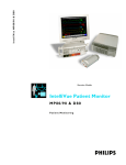
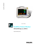
IntelliVue Patient Monitor
MP 60 /7 0
P a t i e nt M o n i t o r i n g
Part Number M8000-9301A
'%(&'
Table of Contents
1
1 Introduction
13
Who Should Use This Guide
How to Use This Guide
Abbreviations
Responsibility of the Manufacturer
Passwords
2 Theory of Operation
Integrated Monitor Theory of Operation
System Boundaries
Hardware Building Blocks
IntelliVue MP60
IntelliVue MP70
Optional Hardware
Compatible Devices
Power Supply
CPU Boards
I/O Boards
Data Flow
Data Acquisition
Data Provider System Service
Persistent Data Storage System Service
Display and User Interface Service
Data Output
Monitor Applications
Internal LAN (Measurement Server Link)
Philips Clinical Network
How does the Support Tool Work with the Monitor
Monitor Software Block Diagram
Block Diagram Legend
3 Testing and Maintenance
Concepts
Test Reporting
Recommended Frequency
Tests Recommended When Performing...
Installation
Repair
13
13
13
14
14
15
15
15
17
17
18
19
19
20
20
22
23
23
23
24
24
24
24
24
26
26
27
28
32
33
33
33
34
35
35
35
3
Preventive Maintenance
Performance Verifications
Upgrades
Tests
Visual Test
Power On Test
NBP Tests
NBP Accuracy Test
NBP Leakage Test
NBP Linearity Test
Valve Test
Sidestream CO2 Performance Test
Barometric Pressure Check and Calibration
Leakage Check
Pump Check
Flow Rate Check and Calibration
Noise Check
CO2 Gas Measurement Calibration Check
Calibration Verification
Reset Time Counters
Temperature Accuracy
ECG/Resp Performance Test
ECG Performance
Respiration Performance
Invasive Pressure Performance Test
SpO2 Performance Test
Cardiac Output Performance Test
Service Tool Procedure, Version 1
Service Tool Procedure, Version 2
BIS Performance Test
PIC/DSC Test
Nurse Call Relay Performance Test
Phone Jack Type Connector Test
Multi-Port Nurse Call Connector Test
ECG Sync Performance Test
VueLink Tests using VueLink Test Module
Test Procedure
Safety Testing
Warnings, Cautions, and Safety Precautions
Safety Test Procedures
Touchscreen Calibration
4 Troubleshooting
Introduction
How To Use This Section
Who Should Perform Repairs
4
35
35
35
36
36
36
36
36
37
37
38
38
39
39
40
40
41
41
42
42
43
43
43
43
44
44
44
44
45
45
45
45
45
46
47
47
47
48
48
49
52
53
53
53
53
Replacement Level Supported
Software Revision Check
Obtaining Replacement Parts
Troubleshooting Guide
Checks for Obvious Problems
Checks Before Opening the Instrument
Checks with the Instrument switched Off
Checks with the Instrument Switched On, AC connected
Initial Instrument Boot Phase
Troubleshooting Tables
How to use the Troubleshooting tables
Boot Phase Failures
Integrated Display is blank
Integrated Touch Display not functioning
External Display is blank
External Touch Display not functioning
General Monitor INOP Messages
Remote Alarm Device
Remote Extension Device
Speed Point
Keyboard/Mouse not functioning
Network related problems
Wireless Network
Multi-Measurement Server
MSL-related problems
Alarm Issues
Alarm Lamps
Alarm Tones
Alarm Behavior
Individual Parameter INOPS
Flexible Module Server
Integrated Module Slots
Printer
Recorder
MIB / RS232
Flexible Nurse Call Relay
Troubleshooting the ECG OUT
Data Flow Marker In and ECG Wave
Status Log
Troubleshooting with the Support Tool
Troubleshooting the Individual Measurements or Applications
53
54
54
54
54
55
55
55
56
58
58
59
61
62
63
64
65
66
66
67
67
69
70
71
72
74
74
74
74
75
76
76
77
78
80
81
81
82
83
83
85
5 Repair and Disassembly
87
Tools Required
87
87
87
Minimal Monitor Disassembly
Disconnecting the SpeedPoint
5
Removing the I/O Boards
Removing the ECG Out board if no SRL2 board is plugged
Removing the Integrated Module Slot, the Measurement Server Mount or blank covers
Separating the front and back half of the monitor
Removing Power Switch board
Removing the Backlights
Further Disassembly
Exchanging the Touchscreen
Exchanging the LCD Assembly
Removing Power Supply
Removing the Speaker
Removing the ECG Out Board with an SRL2 Board plugged
Removing the Video Board
Removing the Main Board
Flexible Module Server (FMS) Disassembly
Removing the Handle and the Measurement Server Mount
Plug-in Modules
Plug-In Module Disassembly
tcpO2/tcpCO2 Calibration Chamber Kit
Recorder Module Paper
Disassembly Procedures for the Measurement Server Extension
Removing the Front Cover
Removing the Extension Bottom Cover
Removing the CO2 Scrubber
Removing the Pump
Refit Procedures for the Measurement Server Extension
Refitting the CO2 Scrubber
Refitting the Pump
Refitting the Extension Bottom Cover
Refitting the Front Cover
General Reassembly/Refitting Comments
Following Reassembly
6 Parts
103
103
107
107
108
109
109
110
110
111
112
113
113
113
114
114
114
114
115
MP60/MP70 Parts
Exchange Parts
Replacement Parts
Flexible Module Server Parts
Exchange and Replacement Parts
Multi-Measurement Server Parts
Measurement Server Extension Parts (M3015A and M3016A)
Exchange Parts List
Plug-in Modules Part Numbers
Part Number Table
Exchange Modules, Table 1
Exchange Modules, Table 2
6
89
90
91
92
94
95
95
95
96
98
99
100
101
101
116
116
117
118
118
119
120
122
124
124
124
125
Plug-In Modules Replaceable Parts
Single-Width Plug-In Module
Double-Width Plug-In Module
Plug-in Module Replaceable Parts
Plug-In Module Language Specific Front Housings, Table 1
Plug-In Module Language Specific Front Housings, Table 2
Plug-In Module Specific Bezels
BIS Module Replaceable Parts
BIS Module Components
tcpO2/tcpCO2 Module Accessories
External Display Part Numbers
Remote Input Devices Part Numbers
Remote Alarm Device Part Numbers
Remote Extension Device Part Numbers
7 Installation Instructions
Unpacking the Equipment
Initial Inspection
Mechanical Inspection
Electrical Inspection
Claims For Damage and Repackaging
Claims for Damage
Repackaging for Shipment or Storage
Installing the Monitor (M8005A or M8007A)
Mounting Instructions
Assembling Mounts
Connections
Installing Interface Boards
Installing Remote Devices
Mounting the Remote Display (M8031A)
Connections
Flexible Module Server and/or Multi-Measurement Server
Attaching the MMS to a Mount
Detaching the Measurement Server from a Mount
Positioning the Measurement Server on a Clamp Mount
Mounting the MMS Mount to the FMS (M8048A)
Mounting the Remote Extension Device to the FMS
Mounting the BIS Module to the FMS
Mounting the FMS
Connections
MSL Cable Termination
Remote Alarm Devices
Mounting
Connections
Remote Extension Device
127
127
127
128
128
129
130
130
131
132
132
133
134
134
134
135
135
136
136
136
136
136
136
136
137
137
138
139
139
139
140
140
140
140
140
141
142
142
143
143
144
146
146
146
147
7
Mounting
Connections
Cabling
Philips Clinical Network
Flexible Nurse Call Relay
Connections
ECG Out Functionality
Connections
Configuration Tasks
Setting Altitude, Line Frequency and Barometric Pressure
Configuring the Equipment Label
8 Site Preparation
Introduction
Site Planning
Roles & Responsibilities
Site Preparation Responsibilities
Procedures for Local Staff
Procedures for Philips Personnel
Monitor M8005A and M8007A Site Requirements
Space Requirements
Environmental Requirements
Temperature
Humidity
Altitude
Electrical and Safety Requirements (Customer or Philips)
Safety Requirements
Electrical Requirements
Remote Device Site Requirements
Multi-Measurement Server M3001A or Flexible Module Server M8048A
Space Requirements Multi-Measurement Server M3001A
Space Requirements Flexible Module Server M8048A
Environmental Requirements Multi-Measurement Server M3001A
Environmental Requirements Flexible Module Server M8048A
Cabling Options and Conduit Size Requirements
Remote Displays (M8031A)
Space Requirements
Environmental Requirements
Electrical and Safety Requirements
Cabling Options and Conduit Size Requirements
Remote Alarm Devices
Space Requirements
Cabling Options and Conduit Size Requirements
Remote Extension Device
Space Requirements
8
147
148
148
149
149
149
149
149
151
151
151
153
153
153
153
153
154
156
156
156
156
156
157
157
157
157
157
157
159
159
159
159
159
160
161
161
161
161
161
163
163
163
163
163
Cabling Options and Conduit Size Requirements
Input Devices
Local Printer
Philips Medical LAN
MIB Interface
Flexible Nurse Call Relay Interface
ECG Out Interface
163
164
164
164
165
165
166
9 Anesthetic Gas Module
167
Introduction
167
167
167
167
168
168
169
169
169
169
170
170
170
171
171
172
172
172
173
174
174
175
175
176
176
176
176
178
178
178
179
180
180
180
181
182
182
Description
Product Structure
Physical Specifications
Environmental Specifications
Performance Specifications
CO2 Measurement
AWRR derived from CO2 Waveform
N2O Measurement
O2 Measurement
Alarm Delay:
Apnea Alarm:
INOP Alarms
General Measurement Principles
Theory of Operation
Main PC Board
Power Supply
Pneumatic System
Pump
Watertrap
Sample Flow Through the Pneumatic Path
Agent Identification Assembly
Measurement Principle
O2 Sensor
Specifications
Measurement Principle
Infrared Measurement Assembly
Installation and Patient Safety
Physical Installation
Environment
Label Sheet
Making Connections to the AGM
Sample Gas Connections to the Gas Exhaust
Returning the Gas Sample
Setting Up the Gas Return
Removing the Gas Sample
Setup and Configuration Procedures
9
Altitude Configuration
Connect Sample Input Tubing
Preventive Maintenance (PM) Tasks
Post-Installation Checks
Safety Requirements Compliance and Considerations
Explanation of Symbols Used
Power Supply Requirements
Grounding the System
Equipotential Grounding
Combining Equipment
Checking and Calibrating the Anesthetic Gas Module
Access Service Functions of the M1026A Anesthetic Gas Module
When and how to check the Philips M1026A Anesthetic Gas Module
Equipment required for checking
Checks and adjustments
Performance Leakage Check
Performance Diagnostic Check
Performance Flowrate Check
Total Flowrate Check and Adjustment in Purge Mode
Measurement Path Flowrate Check and Adjustment
Total Flowrate Check in Normal Mode
Zero Calibration
Barometric Pressure Check and Calibration
Span Calibration Check
Disposal of Empty Calibration Gas Cylinder
Maintaining the Anesthetic Gas Module
Preventive Maintenance (PM) Tasks
Cleaning
Replace PM Parts
Internal Nafion Tubing with Bacterial Filters and manifold Seals
Room-Air Filter
Pump Filter
Performance Checks
Other factors to maximize uptime or reduce cost of ownership:
Troubleshooting the Anesthetic Gas Module
Compatibility Criteria for the AGM and the IntelliVue Monitors
Flow Charts for Communication and Measurement Type Problems
Hardware Related Troubleshooting Strategy
INOPs
Calibration Checks
Calibration Checks Troubleshooting Table
Diagnostic Checks
Problem Solving Hierarchy
Pneumatic System Diagnostic Checks
O2 Assembly Diagnostic Checks
Optical Path Disgnostic Checks
10
182
182
182
183
183
183
184
184
184
185
186
186
187
188
188
188
189
189
190
190
192
192
193
194
197
198
198
198
199
199
200
201
202
202
203
203
203
209
210
213
213
215
215
216
217
219
IR Measurement Assembly Diagnostic Checks
Agent ID Assmebly Diagnostic Checks
Power Supply Diagnostic Checks
Operating Temperature Diagnostic Checks
Test Points, Connectors and Jumpers
Test Points
Connectors
Jumpers
Repairing the Anesthetic Gas Module
Introduction
The Top Cover
Removal
Replacement
Lifting the IR Measurement Mounting Bracket
Removal
Replacement
Infrared Measurement Assembly Head
Transferring NVRAM Data to a Replacement Head
Sample Cell
Removal
Replacement
Solenoid Valve #1
Removal
Replacement
Power Supply Unit
Removal
Replacement
Main PC Board
Removal
Replacement
O2 Sensor
Removal
Replacement
Agent Identification Head
Removal
Replacement
Pump
Removal
Replacement
Fan
Removal
Replacement
Solenoid Valve #2
Removal
Replacement
220
221
222
223
223
223
224
225
227
227
230
230
230
233
233
233
235
235
239
239
239
242
242
242
244
244
244
245
245
246
247
247
248
251
251
251
252
252
252
253
253
254
256
256
256
11
Top Cover PC Board
Removal
Replacement
Watertrap Manifold and Protector
Removal
Replacement
Power Fuses
Removal
Replacement
Test and Inspection Matrix
When to Perform Test Blocks
Safety Test Appendix
Parts List
Calibration Equipment
12
258
258
258
259
259
259
260
260
260
262
266
267
270
274
1
Introduction
1
This Service Guide contains technical details for the IntelliVue MP60 and MP70 Patient Monitor, the
Multi- Measurement Server (MMS), the Flexible Module Server (FMS) and the Measurement Server
Extensions.
This guide provides a technical foundation to support effective troubleshooting and repair. It is not a
comprehensive, in-depth explanation of the product architecture or technical implementation. It offers
enough information on the functions and operations of the monitoring systems so that engineers who
repair them are better able to understand how they work.
It covers the physiological measurements that the products provide, the Measurement Server that
acquires those measurements, and the monitoring system that displays them.
Who Should Use This Guide
This guide is for biomedical engineers or technicians responsible for troubleshooting, repairing, and
maintaining Philips’ patient monitoring systems.
How to Use This Guide
This guide is divided into eight sections. Navigate through the table of contents at the left of the screen
to select the desired topic. Links to other relevant sections are also provided within the individual
topics. In addition, scrolling through the topics with the page up and page down keys is also possible.
Abbreviations
Abbreviations used throughout this guide are:
Name
Abbreviation
IntelliVue MP60/MP70 Patient Monitor
the monitor
Flexible Module Server
FMS
Multi-Measurement Server
MMS
13
1 Introduction
Responsibility of the Manufacturer
Responsibility of the Manufacturer
Philips only considers itself responsible for any effects on safety, reliability and performance of the
equipment if:
• assembly operations, extensions, re-adjustments, modifications or repairs are carried out by persons
authorized by Philips, and
• the electrical installation of the relevant room complies with national standards, and
• the instrument is used in accordance with the instructions for use.
To ensure safety, use only those Philips parts and accessories specified for use with the monitor. If nonPhilips parts are used, Philips is not liable for any damage that these parts may cause to the equipment.
This document contains proprietary information which is protected by copyright. All Rights Reserved.
Reproduction, adaptation, or translation without prior written permission is prohibited, except as
allowed under the copyright laws.
Philips Medizinsysteme Böblingen GmbH
Hewlett-Packard Str. 2
71034 Böblingen, Germany
The information contained in this document is subject to change without notice.
Philips makes no warranty of any kind with regard to this material, including, but not limited to, the
implied warranties or merchantability and fitness for a particular purpose.
Philips shall not be liable for errors contained herein or for incidental or consequential damages in
connection with the furnishing, performance, or use of this material.
Passwords
In order to access different modes within the monitor a password may be required. The passwords are
listed below.
Monitoring Mode: No password required
Configuration Mode: 71034
Demo Mode: 14432
Service Mode: 1345
Consult the configuration guide before making any changes to the monitor configuration.
14
2
Theory of Operation
2
Integrated Monitor Theory of Operation
The IntelliVue Patient Monitor:
• displays real-time data
• controlls the attached measurement servers
• alarms in the case of patient or equipment problems
• offers limited data storage and retrieval (trending)
• interfaces to the Philips Clinical Network and other equipment
A monitor with just a single integrated measurement server can be connected to additional building
blocks to form a monitoring system with a large number of measurements, additional interface
capabilities and multiple slave displays. These elements cooperate as one single integrated real-time
measurement system.
System Boundaries
The following diagram discusses specific boundaries within the overall system with respect to their
openness and real-time requirements:
Philips Clinical Network
15
2 Theory of Operation
Integrated Monitor Theory of Operation
Measurement LAN
combines components of one patient monitor;
real time requirements across all interconnected
elements
Philips Clinical Network (wired LAN)
connects multiple patient monitors,
information centers, application servers; closed
system, only Philips qualified products (tested
and with regulatory approval) are connected,
Philips is responsible for guaranteed real-time
functionality and performance
Philips Clinical Network (wireless)
like Philips Clinical Network (wired) LAN,
however due to current wireless technologies
available it has reduced bandwidth, longer
latencies, reduced functionality
Hospital LAN, Internet
Standard Network, not under Philips control,
no guaranteed service, no real-time
requirements
16
Integrated Monitor Theory of Operation
2 Theory of Operation
Hardware Building Blocks
The following hardware building blocks make up the monitoring system:
IntelliVue MP60
The MP60 monitor:
• integrates the display and processing unit into a single package
• uses a 15” TFT XGA Color display
• uses the Philips SpeedPoint as primary input device; computer devices such as mice, trackball, and
keyboard can be added optionally
• has an optional recorder
• supports the Flexible Module Server (FMS)
Building Blocks:
|| I/F To Local Printer
Power Supply
LCD
Assembly
LCD
Adapter
I/F
Boards
PS/2 To SpeedPoint
MIB To AGM
Main Board
MSL
I/F
Video I/F
Board To Ext. Display
ECG Out
17
2 Theory of Operation
Integrated Monitor Theory of Operation
IntelliVue MP70
The MP70 monitor:
• integrates the display and processing unit into a single package,
• uses a 15” TFT XGA Color display
• uses the Philips Touchscreen as primary input device, whereas the Philips SpeedPoint and computer
devices such as mice, trackball, and keyboard can be added optionally
• has an optional recorder
• supports the Flexible Module Server (FMS)
Building Blocks:
|| I/F To Local Printer
Power Supply
Touch
LCD
Assembly Panel
LCD
Touch
Adapter Controller
I/F
Boards
Main Board
MSL
I/F
Video I/F
Board To Ext. Display
18
PS/2 To External input devices
MIB To AGM
Integrated Monitor Theory of Operation
2 Theory of Operation
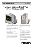
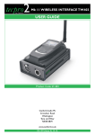
Optional Hardware
A measurement server mount and /or an integrated module slot can be ordered optionally.
Measurement Server
Mount
Integrated
Module Slot
Compatible Devices
Figure 1 M8048A Flexible Module Server (FMS)
Figure 2 M3001A Multi-Measurement Server (MMS)
19
2 Theory of Operation
Integrated Monitor Theory of Operation
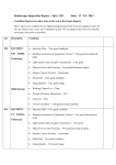
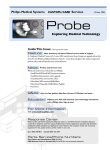
Power Supply
Isolating DC/DC
Converter
AC/DC
Front End
5 V,
Modules
60V
MMS, MMS-EXT
12 V
Backlight
56 V
FMS
48V /120W
Backlight DC/DC Converter
DC/DC
3.3 V
DC/DC
CPU
DC/DC
5V
DC/DC
DC Bus
)
DC/DC
Integrated Module Rack
DC/DC Converter
)
10 V AC
12 Vunreg
I/F boards
HIF, LED’s,
wireless
5V
60 V
Front End
Modules
Figure 3 Power Supply Architecture
The AC/DC converter transforms the AC power coming from the power plug into 48 V/120W DC
source and isolates the monitoring system from the AC power mains.The 48V is distributed via power
bus and supplies power to all the components of the system: The 56 V DC power needed for the FMS,
MMS and measurement server extension is created by an isolating DC/DC converter. The power
needed for the backlights is converted to 12V DC by the backlight DC/DC converter. The CPU is
supplied with 3.3 V and 5 V DC power. The transformation is performed in two steps: The first DC/
DC converter is a power regulator which reduces the variations caused by load changes on the 48V
power bus. The second DC/DC converter converts the power to the needed voltage. Interface boards
require a power of 10V DC. The HIF board and the LEDs are supplied with 12V DC unregulated
power. The integrated module slot requires a 5 V supply for the modules slots and uses the 48V and
another DC/DC converter to create 60 V in order to supply power for the modules.
CPU Boards
The CPU boards have an MPC860 50 MHz processor that provides a number of on-chip,
configurable interfaces. An array of 12 fast UARTS with configurable protocol options are
implemented in an ASIC (along with other system functions such as independent watchdogs etc.),
providing interfacing capabilities to measurement modules and I/O boards. The serial interfaces can
easily be electrically isolated. The main board contains additional video hardware.
20
Integrated Monitor Theory of Operation
Flexible Module Server
&38
%DQNRI,2V
0RGXOHV
2 Theory of Operation
IntelliVue Patient Monitor
&38
9LGHR
%DQNRI,2V
,QWHUIDFHV
Multi-Measurement Server
&38
%DQNRI,2V
0HDVXUHPHQW
$FTXLVLWLRQ
The CPUs provide two LAN interfaces to interconnect CPUs (via the Internal LAN) or to connect to
the Philips Clinical Network.
The CPU capabilities are identical. Different loading options are coded on serial EEPROMs to support
the automatic configuration of the operating system at boot time.
21
2 Theory of Operation
Integrated Monitor Theory of Operation
I/O Boards
Interfaces to the monitor are implemented via I/O boards. The location of these boards is restricted by
general rules. The I/O slot designations diagram and the I/O matrix which outline the I/O board
placement rules can be found in the Installation Instructions section.
The following is a list of Interface (I/O) boards which may be present in your monitor, depending on
your purchased configuration:
• MSL
• Video (analog)
• Philips Clinical Network (LAN)
• PS/2
• MIB/RS232
• Flexible Nurse Call
• Parallel printer
• Remote devices (Remote Alarm Device, Remote Extension Device)
The specifications for the above listed interfaces can be found in the technical data sheet for the
monitor and in the Specifications chapter of the Instructions for Use.
22
Integrated Monitor Theory of Operation
2 Theory of Operation
Data Flow
The following diagram shows how data is passed through the monitoring system. The individual stages
of data flow are explained below.
Display
and User
Interface
Data
Acquisition
Data
Provider
Service
Applications
Persistent
Data
Storage
Data
Output
Data Acquisition
Monitoring data (for example patient measurement data in the form of waves, numerics and alerts) is
acquired from a variety of sources:
• Measurement Servers
The Measurement Servers connected to the internal LAN convert patient signals to digital data and
apply measurement algorithms to analyze the signals.
• External measurement devices
Data can be also acquired from devices connected to interface boards of the monitor. Software
modules dedicated to such specific devices convert the data received from an external device to the
format used internally. This applies to parameter modules and the Anesthetic Gas Module
• Server systems on the Philips Clinical Network
To enable networked applications such as the other bed overview, data can be acquired from server
systems attached to the Philips Clinical Network, for example a Philips Information Center
Data Provider System Service
All data that is acquired from measurement servers or external measurement devices is temporarily
stored by a dedicated data provider system service. All monitor applications use this central service to
access the data in a consistent and synchronized way rather than talking to the interfaces directly.
This service makes the applications independent of the actual type of data acquisition device.
23
2 Theory of Operation
Integrated Monitor Theory of Operation
The amount of data stored in the data provider system service varies for the different data types. for
example several seconds of wave forms and the full set of current numerical values are temorarily stored
in RAM.
Persistent Data Storage System Service
Some applications require storage of data over longer periods of time. They can use the persistent data
storage system service. Dependent on the application requirements, this service can store data either in
battery backed-up (buffered) memory or in flash memory. The buffered memory will lose its contents
if the monitor is without power (not connected to mains) for an extended period of time. The flash
memory does not lose its contents.
The trend application for example stores vital signs data in a combination of flash memory and
buffered memory, while the system configuration information (profiles) is kept purely in flash
memory.
Display and User Interface Service
Applications can use high level commands to display monitoring data or status and command windows
on the internal LCD panel. These commands are interpreted by the display manager application. This
application controls the dedicated video hardware which includes video memory and a special ASIC.
User input is acquired from a variety of input devices, for example the SpeedPoint, the touchscreen or
other standard input devices (keyboard, mouse) which may be attached to I/O boards. The system
software makes sure that the user input is directed to the application which has the operating focus.
Data Output
The monitoring system is very flexible and customizable regarding its data output devices. Built-in
devices (for example LAN, alarm lamps, speaker, video) provide the basic output capabilities.
These capabilities can be enhanced by adding additional I/O boards, as required in the specific enduser setup. The additional I/O boards typically provide data to externally attached devices, for example
to printers, RS232 based data collection devices, nurse call systems etc.
The monitor can identify I/O boards by means of a serial EEPROM device that stores type and version
information. The operating system detects the cards and automatically connects the I/O board with the
associated (interface driver) application. For some multi- purpose cards it is necessary to configure the
card for a particular purpose first (for example the dual MIB/RS232 card can support external touch
display, data import, data export).
Monitor Applications
The monitor applications provide additional system functionality over the basic measurement and
monitoring capabilities. This includes for example trending, report generating, event storage or derived
measurements.
In general, the monitor applications use the data provider system service to access the measurement
data. Application interfaces to the other system services allow the application to visualize data, to store
data over extended periods of time or to output data to other devices.
Internal LAN (Measurement Server Link)
All components of the monitoring system (including measurement servers and CPUs in the monitor)
communicate using an IEEE802.3/ Ethernet LAN in the Measurement Server Link (MSL). This
network is used to distribute data between the components, for example:
24
Integrated Monitor Theory of Operation
2 Theory of Operation
• Digitized patient signals including wave data, numerical data and status information (typically from
the measurement server to a display unit)
• Control data representing user interactions (typically from the display unit to a measurement server)
• Shared data structures, for example representing patient demographical data and global
configuration items
The internal LAN allows plug and play configuration of the monitoring system. The system
automatically detects plugging or unplugging of measurement servers and configures the system
accordingly.
The components on the internal LAN are time- synchronized to keep signal data consistent in the
system. Dedicated hardware support for synchronization eliminates any latency of the network driver
software.
The integrated LAN provides deterministic bandwidth allocation/ reservation mechanisms so that the
real-time characteristic of signal data and control data exchange is guaranteed. This applies to the data
flow from the measurement server to the monitor (for example measurement signal data) and the data
flow from the monitor to a measurement server (for example to feed data to a recorder module).
Integrated communication hubs in the monitor and the FMS allow flexible cabling options (star
topology, daisy chaining of servers).
MDSE
Internal LAN
MDSE
MDSE
Internal
LAN
Internal
LAN
25
2 Theory of Operation
Integrated Monitor Theory of Operation
Philips Clinical Network
The monitoring system may be connected to the Philips Clinical Network, for example to provide
central monitoring capabilities or other network services. This connection may be through a normal
wired connection or through a wireless connection.
The monitor supports the connection of an external off-the-shelf wireless adapter. This allows a simple
field upgrade as well as a technology upgrade in the future. Switching between wired and wireless
networks is automatically triggered by the plugging or unplugging of the network cable.
The Philips Clinical Network protocols function very similarly to the protocols used on the internal
LAN.
After configuration, the monitoring system sends the digitized patient signals including wave data,
numerical data and status information onto the network. Control data representing user interactions
can be exchanged between the monitoring system and a central station bi-directionally.
Additional protocols are supported for networked applications, for example for the other bed overview
function, which allows viewing of monitoring data from other patients on the network.
For plug and play operation, the monitoring system uses the standard BootP protocol to automatically
acquire a network address.
How does the Support Tool Work with the Monitor
The support tool is an NT application typically installed on the laptop of a customer engineer or a
biomedical engineer working in the customer’s own service department.
The purpose of the support tool is to upgrade, configure and diagnose all monitoring components
(modules, measurement servers, and monitors) in the system over the network. The monitors route
network traffic between the Philips Clinical Network to the internal LAN.
The service protocol developed for this purpose uses a raw access to the devices without the need for IP
addresses etc. over a standard customer network installation, so that even defective devices can be
upgraded as long as the few kBytes of initial boot code are working. The boot code itself can also be
upgraded using the same protocol.
The tool allows access to internal service information and to serial numbers. It can be remotecontrolled, for example via a dial-up connection from a response center, provided the proper
infrastructure is in place.
For details see the Instructions for Use for the Support Tool.
26
Integrated Monitor Theory of Operation
2 Theory of Operation
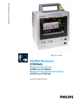
Monitor Software Block Diagram
Figure 4 shows the functional block diagram for the monitoring system. A legend explaining terms and
diagram elements follows. The information below varies depending on the purchased monitor options.
Philips Clinical
Network
Video Out
Color LCD
Display
Visual
Indicators
LEDs
Audio
Indicators
Input Devices
(including PS/2)
Loudspeaker
Touch
Trim Knob
ECG-Out
Marker-In
Interfaces
LAN
ECG-Out
Marker-In
Interface Managers
MDSE
Record
Alarm
Reports
Applications
System Services
Real Time Operating System
Trend
Calc Param
HiRes
ADT
Events
MDSE
RS-422
LAN
LAN
RS-422
M3001A MultiMeasurement Server
M3015/16A
Measurement Server
Extension
LAN
RS-422
Flexible
Module
Server
M1029A
Temp
M1032A
VueLink
CO2, Press/Temp
12-lead ECG/Resp, NBP, SpO2,
Press/Temp
M1006B
Press
M1012A
C.O.
M1018A
tcPO2/CO2
M1116B
Recorder
Plug-In Modules
Figure 4 IntelliVue Patient Monitoring System Functional Block Diagram
27
2 Theory of Operation
Integrated Monitor Theory of Operation
Block Diagram Legend
Functional Block
Description
Services
Operating System
The Operating System (OS) provides a layer of isolation between
the specific hardware implementation and the application
software. The OS performs system checks and allocates resources
to ensure safe operation when the system is first started. This
includes internal self-tests on several hardware modules and
configuration checks for validity of configuration with the
operating software. During normal operation, the OS continues
to run checks on system integrity. If error conditions are detected
the OS will halt monitoring operations and inform the operator
about the error condition.
System Services
The System Services provide generic common system services.
In particular:
It uses a real-time clock component to track time. It synchronizes
to network time sources and verifies the accuracy of the system
time information. It is also responsible for managing persistent
user configuration data for all Measurement Servers, Flexible
Module Servers and IntelliVue Patient Monitoring System
software modules. User configuration data is stored in a nonvolatile read/write storage device
Applications
Reports
The Reports Service retrieves current and stored physiological
data and status data to format reports for printing paper
documentation. The following reports are supported:
• Vital Signs Report
• Graphical Trend Report
• Event Review Report
• Event Episode Report
• ECG Report (12 Lead/Multi-Lead)
• Cardiac Output Report
• Calculations Report (Hemodynamic/Oxygenation/
Ventilation)
• Calculations Review Report
• Wedge Report
• Test Report
• Other reports (e.g. Loops, Review Applications, Drug
report)
The Reports service generates report data which can be printed
on a local or a central printer.
28
Integrated Monitor Theory of Operation
2 Theory of Operation
Functional Block
Description
Record
The Record Service retrieves current and stored physiological
data and status data to format a continuous strip recording. A
recording can be triggered manually by the operator or
automatically by an alarm condition. The Record Service uses the
services of the Recorder Interface to control an M1116B
Recorder in the FMS. The Record Service can also send data to a
central recorder.
Alarm
The Alarm Service contains logic that prioritizes alarm conditions
that are generated either by the Measurement Servers, Flexible
Module Server, or by IntelliVue Patient Monitoring System
software modules. Visual alarm signals (messages) are displayed at
the top of the IntelliVue Patient Monitoring System display and
alarm sounds are generated by a loudspeaker. Alarm conditions
may be generated when a physiological parameter exceeds
preselected alarm limits or when a physiological parameter or any
other software module reports an inoperative status (technical
alarm, for example, the ECG leads may have fallen off the
patient). The Alarm service manages the alarm inactivation states,
for example suspension of alarms, silencing of alarms, and alarm
reminder. Alarm signals may also be configured as latching
(alarm signals are issued until they are acknowledged by the
operator, even when the alarm condition is no longer true). The
Alarm service controls the visual alarm signals (alarm lamps).
Trend
The Trend service stores the sample values of physiological data
and status data with a resolution of 12 seconds, 1 minute or 5
minutes for a period of up to 48 hours. The data is kept in
battery buffered read/write storage and flash memory devices to
be preserved across power failures. The stored data is protected
via consistency checks and checksums. When a new patient is
admitted, the trend database erases all data of the previous
patient.
HiRes
The OxyCRG (Oxygen CardioRespiroGram) service derives a
high-resolution trend graph from the Beat-to-Beat Heart Rate,
SpO2 or tcpO2, and Respiration physiological data. The
OxyCRG is specialized for neonatal applications, allowing the
opeartor to identify sudden drops in Heart Rate (Bradycardia)
and SpO2 or tcpO2 (Desaturations), and supporting the operator
in visualizing Apnea situations.
ADT
The ADT (Admit/Discharge/Transmit) service maintains the
patient demographics information. The operator may admit a
new patient, discharge the old patient and enter or modify the
patient demographics. The ADT service also supports the
transport of a patient (trend database) with the M3001A MultiMeasurement Server. The ADT service controls the deletion of
old patient data, the upload of trend data from the M3001A and
the switching back of all settings to user defaults. It also
synchronizes patient information with a central station on the
network.
29
2 Theory of Operation
Integrated Monitor Theory of Operation
Functional Block
Description
Calc Param
The Calc Param (Calculated Parameters) service accesses current,
stored and manually entered physiological data as input to
calculation formulas. With these formulas, derived
hemodynamic, oxygenation and ventilation variables are
computed. The calculation results, including the input
parameters, are stored for later review using the Trend service.
Interface Managers
MDSE
The MDSE (Medical Data Service Element) Interface Manager is
responsible for the exchange of real-time data between the
IntelliVue Patient Monitoring System display unit and the
Measurement Servers and Flexible Module Server as well as
between the IntelliVue Patient Monitoring System display unit
and other devices attached to the network. MDSE establishes and
maintains a data communication link between the devices. It
provides configuration information about the remote device to
applications in the local device and it allows the exchange of
measurement data and status information between the devices.
Printer
The Printer Interface Manager provides a high level interface to a
printer. It provides means to:
• establish a connection to the printer
• transfer data to the printer
• get status of the printer
• close connection to the printer
The Printer Interface Manager also supervises the connection to
the printer and whether the printer accepts data (for example
paper out). The Printer Interface Manager notifies the operator
in such cases.
30
Integrated Monitor Theory of Operation
2 Theory of Operation
Functional Block
Description
Display & Operator Interface
The Display and Operator Interface Manager performs the
following tasks:
• Screen presentation of real-time and stored physiological
measurement data, alarm condition data and status
information received from the MDSE interface manager,
the Alarm service or other IntelliVue Patient Monitoring
System modules
• Screen presentation of operating controls (control
windows)
• Processing of operating control commands received from
HIF Control interface. The module verifies and interprets
the received commands and forwards them to other
software modules of the IntelliVue Patient Monitoring
System display unit, Measurement Servers or Flexible
Module Server
• Sound generation (issues audible alarm signals and
generates audible information signals, for example QRS
and SpO2 tones, operator audible feedback)
Interfaces
LAN
The LAN interface implements the physical layer of IEEE 802.3.
The LAN interface performs Manchester encoding/decoding,
receive clock recovery, transmit pulse shaping, jabber, link
integrity testing, reverse polarity detection/correction, electrical
isolation, and ESD protection. Electronically separated interfaces
are used for communication to the Measurement Servers or
Flexible Module Server and to the network.
Centronics
The Centronics interface implements the standard signaling
method for bi-directional parallel peripheral devices according to
IEEE 1284-I. The interface is used as a parallel interface to a
standard printer with electrical isolation and ESD protection.
Display Controller
The Display Controller Interface consists of a video controller
chip, video RAM and the controlling software. The Display
Controller interface processes the high level display commands
(character and graphic generation, wave drawing) and translates
them into pixels, which are written into the video RAM where
the video controller chip generates the video synchronization
signals and the pixel stream for the Color LCD Display.
HIF Control
The HIF (Human Interface Control) interface scans the Human
Interface devices for operator controls (Touch Screen, Trim
Knob, and PS/2 devices), formats the collected data and sends it
to the display and Operating Interface.
31
2 Theory of Operation
32
Integrated Monitor Theory of Operation
Functional Block
Description
ECG-Out Marker-In
The ECG Out/Marker In interface receives the ECG waveform
directly from the ECG/Resp Arrhythmia ST-Segment
physiological algorithm via an RS-422 serial interface and
converts the digital ECG signal to an analog ECG signal. In
addition, the ECG Out controller receives from a connected
device the marker information and forwards this data to the
ECG/Resp Arrhythmia ST-Segment physiological algorithm.
The converted analog signal is used to synchronize a connected
device to the patient’s ECG
RS-422
The serial link RS-422 interface communicates the ECG signal
to the ECG Output/Marker In of the IntelliVue Patient
Monitoring System display unit. The interface is a serial,
differential, full-duplex link. The interface is ESD protected.
PS/2
The PS/2 interface supports the serial protocol of standard PS/2
devices (mouse). The PS/2 serial protocol is interpreted by the
HIF Control interface.
3
Testing and Maintenance
3
Concepts
This chapter provides a checklist of the testing and maintenance procedures for the monitor, the MMS
the Measurement Server Extensions and the FMS associated modules.
Preventive Maintenance refers specifically to the series of tests required to make sure the Instrument
measurement results are accurate. The measurements requiring these reported tests are NBP and
sidestream CO2. The accuracy and performance procedures are designed to be completed when
readings are in question or as specified.
Test Reporting
Authorized Philips personnel report test results back to Philips to add to the product development
database. Hospital personnel, however, do not need to report results. This table shows you what to
record on the service record after completing the tests in this chapter.
Test
What to record
Visual
V:P or V:F
Power On
PO:P or PO:F
P NIBP
PN:P/X1/X2/X3/X4 or
PN:F/X1/X2/X3/X4
P CO2
PCO2:P/X1/X2/X3/X4/X5/X6/X7/X8 or
PCO2:F/X1/X2/X3/X4/X5/X6/X7/X8
Safety
S(1):P/x1/x2 or
S(1):F/x1/x2
S(2): P/x1 or
S(2): F/x1
S(3): P/x1 or
S(3): F/x1
Where P = Pass, F = Fail and X/x are the measured values as defined in the tests described in this
chapter.
33
3 Testing and Maintenance
Recommended Frequency
Recommended Frequency
The testing checklist appears in the next section of this chapter. Perform the procedures as indicated in
the suggested testing timetable. These timetable recommendations do not supersede local
requirements.
Suggested Testing Timetable
Frequency
Preventive Maintenance Tests
Required
• NBP Calibration
• Once a year, or as specified by local laws.
• Sidestream CO2 Calibration
• Once a year or after 4,000 hours continuous
use and following any instrument repairs or
the replacement of any instrument parts.
• CO2 pump / CO2 scrubber replacement
• Once every three years or after 15 000
operating hours
Performance and Safety Tests
Recommended: Once every two years, or if
you suspect the measurement is incorrect
• Temperature Accuracy
• ECG/Resp Performance
• Invasive Pressure Performance
• SpO2 Performance
• Mainstream CO2 Performance
• EEG Performance
• C.O. Performance
• BIS Performance
• SvO2 Performance
• tcGas Performance
• VueLink Performance
• Nurse Call Relay Performance*
• ECG Sync Performance*
*Only when in use as part of hospital protocols
Safety Checks (in accordance with IEC 606011)
• System Enclosure Leakage Current
• Protective Earth
• Patient Leakage Current
34
Recommended: Once every two years and after
repairs where the power supply is replaced or
the monitor has been damaged by impact.
Tests Recommended When Performing...
3 Testing and Maintenance
Tests Recommended When Performing...
Installation
Service Event
Test Blocks Required
(When performing...
...Complete these tests)
Installation of monitor with no display connected
to the VGA output
Perform Visual and Power On Test Blocks
Installation of monitor with a display connected
to the VGA output
Perform Visual, Power On and Safety (1) Test
Blocks
Service Event
Test Blocks Required
(When performing...
...Complete these tests)
Repairs of M3015A
Perform Power On and M3015A tests
Repairs where the monitor has been damaged by
impact
Perform Power On and Safety (2) and (3) Test
Blocks
Repairs where the power supply is replaced
Perform Safety (2) Test Block
All other IntelliVue Monitoring System repairs
Perform Power On Test Block
Repair
Preventive Maintenance
Perform preventive maintenance tests:
• NBP calibration
• Sidestream CO2 calibration
• Pump and scrubber replacement.
Performance Verifications
Perform all safety, accuracy and performance test procedures listed in the following sections. If a
particular measurement is in question, perform the measurement performance test only.
Upgrades
Service Event
Test Blocks Required
(When performing...
...Complete these tests)
Hardware and software upgrades
Perform Power On Test Block unless otherwise
specified in the Upgrade Installation Notes shipped
with the upgrade.
35
3 Testing and Maintenance
Tests
Tests
Some of the following testprocedures must be performed in service mode. To enter service mode select
Operating Modes in the main menu. Then select Service Mode and enter the password.
If required, open the screen menu in the monitor info line at the top of the screen and select
Service to access the service screen. This is required particularly for Anesthetic Gas Module testing
procedures.
Visual Test
Inspect the system for obvious signs of damage. Also check external leads and accessories.
The expected test result is pass: the system has no obvious signs of damage.
Power On Test
1
Switch on the monitor and connect the MMS.
2
Observe whether the system boots up successfully and if an ECG wave appears on the screen.
The expected test result is pass: the monitor boots up and displays an ECG wave. The wave might be a
flat line if no simulator is attached.
NBP Tests
This section describes NBP test procedures.The monitor must be in service mode to perform these
tests.
NBP Accuracy Test
This test checks the performance of the non-invasive blood pressure measurement. Connect the
equipment as shown:
To NBP Input
Expansion Chamber
Tubing
Manometer
Tools required:
• Reference manometer (includes hand pump and valve), accuracy 0.2% of reading.
• Expansion chamber (volume 250 ml +/- 10%)
• Appropriate tubing.
In service mode, the systolic and diastolic readings indicate the noise of NBP channels 1 and 2
respectively. When static pressure is applied, the reading in NBP channel 1 should be below 50. The
value in parentheses indicates the actual pressure applied to the system.
36
Tests
3 Testing and Maintenance
1
Connect the manometer and the pump with tubing to the NBP connector on the MMS and to the
expansion chamber.
2
In service mode, select the Setup NBP menu.
3
Select Close Valves: On
4
Raise the pressure to 280 mmHg with the manometer pump.
5
Wait 10 seconds for the measurement to stabilize.
6
Compare the manometer values with the displayed values.
7
Document the value displayed by the monitor (x1).
8
If the difference between the manometer and displayed values is greater than 3 mmHg, calibrate
the MMS. If not, proceed to the leakage test.
9
To calibrate the MMS, select Close Valves off then Calibrate NBP and wait for the
instrument to pump up the expansion chamber.Wait a few seconds after pumping stops until
EnterPrVal is highlighted and then move the cursor to the value shown on the manometer. If
one of the following prompt messages appears during this step, check whether there is leakage in
the setup:
– NBP unable to calibrate–cannot adjust pressure
– NBP unable to calibrate–unstable signal
10 Press Confirm.
If the INOP NBP Equipment Malfunction message occurs in monitoring mode, go back to service
mode and repeat the calibration procedure.
NBP Leakage Test
The NBP leakage test checks the integrity of the system and of the valve. It is required once per year
and when you repair the monitor or replace parts.
1
If you have calibrated, repeat steps 2 to 6 from the accuracy test procedure so that you have 280
mmHg pressure on the expansion chamber.
2
Watch the pressure value for 60 seconds.
3
Calculate and document the leakage test value (x2).
x2 = P1 - P2
where P1 is the pressure at the beginning of the leakage test and P2 is the pressure displayed after
60 seconds.
The leakage test value should be less than 6 mmHg.
NBP Linearity Test
1
Reduce the manometer pressure to 150 mmHg.
2
Wait 10 seconds for the measurement to stabilize.
3
After these 10 seconds, compare the manometer value with the displayed value.
4
Document the value displayed by the monitor (x3)
5
If the difference is greater than 3 mmHg, calibrate the MMS (see steps 9 to 10 in the accuracy test
procedure).
37
3 Testing and Maintenance
Tests
Valve Test
1
Raise the pressure again to 280 mmHg.
2
Select Close valves: Off.
3
Wait five seconds and then document the value displayed. The value should be less than 10
mmHg.
4
Document the value displayed by the monitor (x4).
Test
Expected test results
Accuracy test
x1 = value displayed by monitor
Difference ≤ 3mmHg
Leakage test
x2 = leakage test value
x2 < 6 mmHg
Linearity test
x3 = value displayed by monitor
Difference ≤ 3mmHg
Valve Test
x4 = value < 10 mmHg
Sidestream CO2 Performance Test
Allow five seconds between individual service procedures to ensure stable equipment conditions. When
certain monitor procedures are running, service procedures are not possible and trying to start them
will result in a message Service Operation Failed in the monitor’s status line. Wait until
the monitor completes the current operation, then restart the service procedure.
This test checks the performance of the CO2 measurement for the sidestream extension. The CO2
performance test is required once per year and when the instrument is repaired or when parts are
replaced.
This test uses calibration equipment that you can order (see the Parts section for the part number). The
procedure is summarized in the following steps. Refer to the documentation accompanying the
equipment for detailed instructions.
Tools Required:
• Standard tools, such as screwdriver, tweezers
• Electronic flowmeter, M1026-60144.
• Gas calibration equipment:
• Cal 1 gas 15210-64010 (5% CO2)
• Cal 2 gas 15210-64020 (10% CO2)
• Cal gas flow regulator M2267A
• Cal tube 13907A
You also need a local barometric pressure rating received from a reliable local source (airport, regional
weather station or hospital weather station) which is located at the same altitude as the hospital.
The CO2 calibration for the sidestream extension consists of the following steps:
• Barometric pressure check and calibration, if required.
38
Tests
3 Testing and Maintenance
• Leakage check
• Pump check
• Flow check and calibration, if required.
• Noise check
• CO2 Cal check and calibration, if required.
• CO2 Cal verification using 2nd cal gas
Perform all checks in the same session.
Barometric Pressure Check and Calibration
Check the barometric pressure value in the sidestream CO2 extension as follows:
1
Go into service mode and select Setup CO2 menu.
2
Connect a FilterLine to the sidestream CO2 input. This activates the pump in the sidestream CO2
Extension.
3
The status line at the bottom of the screen displays “CO2 pressure reading (ambient/cell) xxx/yyy”
where xxx is the ambient pressure and yyy is the measured cell pressure. Check whether the
ambient pressure value (x1) matches (within the acceptable tolerance of ±12mm Hg) the reference
value you have received. If so, proceed to the leakage check. If the value is not correct, calibrate as
follows.
a. Select CO2 then select Barom.Press to activate a table of values.
b. Select the value in the table which matches the reference value received from a reliable local
source (airport, regional weather station or hospital weather station). (The values are displayed
with a resolution of 2 mmHg up to 500 mmHg and a resolution of 1 mmHg from 500 mmHg
to 825 mmHg.) Note: the selected value must be within ±10% of the current measured ambient
pressure, otherwise an error message will occur at restarting the monitor.
c. Confirm the barometric pressure setting.
d. Check that the ambient pressure displayed in the status line at the bottom of the screen is the
same as the value which you selected from the list in step b.
Leakage Check
The leakage check consists of checking the tubing between:
• the pump outlet and the measurement server extension outlet and
• the pump inlet and FilterLine inlet.
Check the user’s guide of the flowmeter for details on how to make a correct flow reading.
Part 1
1
Go into service mode and select Setup CO2 menu.
2
Connect a FilterLine to the sidestream CO2 input to start the pump running.
3
Check the ambient pressure and the cell pressure shown in the monitor’s status line. The cell
pressure should be approximately 20 mmHg lower than ambient pressure.
4
Connect the flowmeter outlet to the FilterLine inlet using a flexible connecting tube.
39
3 Testing and Maintenance
Tests
5
Block the measurement server extension outlet using your fingertip and observe the flowmeter
display. The value on the flowmeter (x2) should decrease to between 0 and 4 ml/min,
accompanied by an audible increase in pump noise. If the value is within the tolerance limits,
continue with part 2 of the leakage check.
6
If the value is outside the tolerance limits, there is a leakage between the pump outlet and the
measurement server extension gas outlet.
7
Open the measurement server extension and check the tubing connections at the pump outlet and
the extension gas outlet. If the connections are good, then there is a leakage in the tubing and you
must exchange the measurement server extension.
Part 2
1
Disconnect the flowmeter from the Part 1 setup and connect the flowmeter inlet to the M3015A
gas outlet.
2
Leave the Filterline connected to the M3015A inlet.
3
Block the inlet of the FilterLine using your fingertip and observe the flowmeter display. The value
on the flowmeter (x3) should decrease to between 0 and 4 ml/min, accompanied by an audible
increase in pump noise. Do not block the inlet for longer than 25 seconds as this will lead to an
“Occlusion” INOP. If the value is within the tolerance limits, there are no leakages and the leakage
check is completed; proceed to the pump check.
4
If the value is not within the tolerance limits, there is a leakage between the FilterLine inlet and the
pump inlet.
5
Check the FilterLine connections and open the M3015A to check the tubing connections at the
pump inlet and the M3015A gas inlet. If the connections are good, try replacing the FilterLine and
repeating the leakage check. If the situation remains, there is a leakage in the tubing and the
M3015A must be exchanged.
Pump Check
1
Connect the flowmeter inlet to the M3015A gas outlet.
2
Connect the FilterLine to the M3015A inlet.
3
Block the inlet of the FilterLine using your fingertip and observe the cell pressure on the M3046A
display. The cell pressure (x4) should be more than 120 mmHg below the ambient pressure
shown. If the pressure difference is less than 120 mmHg, the pump is not strong enough and you
should replace it, irrespective of the Pump OpTime.
Flow Rate Check and Calibration
Check the flow rate in the sidestream CO2 extension as follows:
40
1
Connect the flowmeter to the CO2 FilterLine.
2
Check on the flowmeter the flow that the sidestream CO2 extension pump draws (x5). It should be
50 ml/min ± 7.5 ml/min. If the value is within tolerance, proceed to the CO2 Gas calibration
check. If the value is not within tolerance, calibrate as follows.
3
Adjust the flow in the instrument by selecting Increase Flow or Decrease Flow until it
is as close as possible to 50 ml per minute as indicated on the flowmeter gauge.
Tests
3 Testing and Maintenance
4
When you are satisfied that the flow is set as close as possible to 50 ml per minute, select Store
Flow and confirm the setting. If you do not store the adjusted flow within 60 seconds of the
adjustment, the old flow setting is restored.
5
If you cannot adjust the flow to within tolerance, replace the pump. If you still cannot make the
flow adjustment, this indicates a fault in the measurement extension, which must be replaced.
Noise Check
2
With the monitor in service mode, select Setup CO2 menu.
Disconnect the flowmeter and connect the 5% calibration gas and flow regulator in its place.
3
Open the valve to apply the 5% calibration gas and wait until the value is stable.
4
Check the noise index (x6) displayed next to the CO2 value on the display (this indicates the level
of noise on the CO2 wave). If the value exceeds 3 mmHg, replace the measurement extension.
1
CO2 Gas Measurement Calibration Check
After switching the measurement extension on, wait at least 20 minutes before checking the
calibration. Check the calibration of the CO2 gas measurement as follows:
1
Check that the 5% calibration gas and flow regulator are connected.
2
Calculate the expected measurement value in mmHg as follows:
0.05 x (ambient pressure) = value mmHg
for example 0.05 x 736 = 36.8 mmHg (with an ambient pressure of 736 mmHg)
3
Open the valve on the flow regulator to allow 5% CO2 gas to flow into the extension. Allow the
value to stabilize.
4
Check that the value on the instrument (measurement value on the main screen, x7)) matches the
calculated mmHg value ± 2.6 mmHg. If the value is outside the tolerance, calibrate as described in
step 9 in this procedure onwards.
5
Disconnect the 5% calibration gas and connect the 10% calibration gas.
6
Calculate the expected measurement value and tolerance in mmHg as follows:
0.1 x (ambient pressure) = value mmHg
±0.07 x (value mmHg) = tolerance
for example 0.1 x 737 mmHg = 73.7 mmHg (with an ambient pressure of 737 mmHg)
±0.07 x 73.7 mmHg = ±5.16 mmHg tolerance
7
Open the valve on the flow regulator to allow 10% CO2 gas to flow into the extension. Allow the
value to stabilize.
8
Check that the value on the instrument (x8) matches the calculated mmHg value within the
calculated tolerance. If so, the measurement extension is correctly calibrated. If the value is outside
the tolerance, calibrate as follows.
9
If not already connected, connect the 5% calibration gas.
10 Select Cal. CO2.
11 Select the value for the calibration gas. (The default value is 5.0%.)
41
3 Testing and Maintenance
Tests
12 Open the valve on the calibration gas to allow CO2 gas to flow into the extension. Allow the value
to stabilize before the start of the calibration. Leave the valve open until the instrument gives a
prompt that gas can be removed.
13 The extension calibrates and prompts when calibration is successful.
Calibration Verification
1
Reopen the 5% gas valve and allow the value to stabilize.
2
Check that the value displayed on the monitor is correct within the tolerance (see step 2 above).
3
Disconnect the 5% calibration gas and connect the 10% calibration gas.
4
Open the valve on the flow regulator to allow 10% CO2 gas to flow into the extension. Allow the
value to stabilize.
5
Check that the value displayed on the monitor is correct within the tolerance (see step 6 above).
If one or both values are not within tolerances, you must exchange the measurement server extension.
Reset Time Counters
You must check the time counters on the sidestream CO2 extension before calibrating the instrument.
As well, when parts are replaced, the appropriate counters must be reset to zero.
The counters for CO2 pump, IR Src and Last Cal are displayed in the status line. The values are
updated when entering the Setup CO2 menu.
Observe the following guidelines:
• When calibrating the CO2 extension, if no parts have been replaced, check the displayed values of
Reset PumpOpTime and Reset IRSourceTime selections to make sure that they are
within suggested guidelines for use (15, 000 hours of continuous use). If the counter time is greater
than 15, 000 hours, replace the appropriate part. See Repair and Disassembly for details.
• When calibrating the CO2 extension, if parts have been replaced, reset the appropriate values using
the Reset PumpOpTime and Reset IRSourceTime selections. See Repair and Disassembly
for details.
Resetting the PumpOpTime generates the INOP: “CO2 OCCLUSION”. To clear this INOP you
must perform a flow check and store the flow in service mode (select Store Flow).
Table 1 Documenting CO2 Test Results
Test
Expected Test Results
Barometric Pressure
Check
x1 = difference between the reference pressure and the
measured ambient pressure displayed on the monitor
(x1<12 mmHg)
Leakage Check parts
1 and 2
x2 = value of part 1 leakage check on flowmeter
(x2< 4.0 ml/min)
x3 = value of part 2 leakage check on flowmeter
(x3< 4.0 ml/min)
42
Tests
3 Testing and Maintenance
Table 1 Documenting CO2 Test Results
Test
Expected Test Results
Pump Check
x4 = difference in pressure between cell pressure and ambient
pressure displayed on the monitor during occlusion (x4 >120
mmHg)
Flow Check
x5 = difference between measured value and 50.0 ml/min
(x5<7.5 ml/min)
Noise Check
x6 = noise index displayed on monitor (x6<3.0)
CO2 Gas
Calibration Check
x7 = difference between measured CO2 value and calculated
value, based on 5% CO2 cal. gas. (x7 < 2.6 mmHg)
CO2 Cal
Verification
x8 = difference between measured CO2 value and calculated
value, based on 10% CO2 cal. gas.
(x8 < ± {0.07 x value calculated})
Temperature Accuracy
This test checks the performance of the temperature measurement.
Tools required: Patient simulator (with 0.1oC or 0.2oF).
1
Connect the patient simulator to the temperature connector on the MMS or measurement server
extension.
2
Configure the patient simulator to 40 oC or 100 oF.
3
The value should be 40 oC ± 0.2 oC or 100 oF ± 0.4 oF.
ECG/Resp Performance Test
This test checks the performance of the ECG and respiration measurements.
Tools required: Patient simulator.
ECG Performance
1
2
Connect the patient simulator to the ECG/Resp connector on the measurement server.
Configure the patient simulator as follows:
– ECG sinus rhythm.
– HR = 100 bpm.
3
Check the displayed ECG wave and HR value against the simulator configuration.
4
The value should be 100bpm +/- 2bpm.
Respiration Performance
1
Change the Patient Simulator configuration to:
– Base impedance line 1500 Ohm.
– Delta impedance 0.5 Ohm.
– Respiration rate 40 rpm.
43
3 Testing and Maintenance
2
Tests
The value should be 40 rpm +/- 2 rpm.
Invasive Pressure Performance Test
This test checks the performance of the invasive pressure measurement.
Tools required: Patient simulator.
1
Connect the patient simulator to the pressure connector on the MMS or the measurement server
extension.
2
Set the patient simulator to 0 pressure.
3
Make a zero calibration.
4
Configure the patient simulator as P(static) = 200 mmHg.
5
Wait for the display.
6
The value should be 200 mmHg ± 5 mmHg. If the value is outside these tolerances, calibrate the
MMS or measurement server extension. If the MMS was calibrated with a dedicated reusable
catheter, check the calibration together with this catheter.
SpO2 Performance Test
This test checks the performance of the SpO2 measurement.
Tools required: none
1
Connect an adult SpO2 transducer to the SpO2 connector on the MMS.
2
Measure the SpO2 value on your finger (this assumes that you are healthy).
3
The value should be between 95% and 100%.
Cardiac Output Performance Test
These tests check the performance of the cardiac output measurement.
1
Connect the patient simulator to the C.O. module using the patient cable.
2
Configure the patient simulator as follows:
Injection temperature: 2 °C
Computation Const: 0.542
(Edward's Catheter)
Flow: 5 l/min
3
Check displayed value against the simulator configuration.
4
Expected test result: C.O. = 5 +/– 1 l/min.
Service Tool Procedure, Version 1
This procedure applies for Service Tool M1012-61601 and/or C.O. modules without option C10.
1
In monitoring mode, connect the C.O. interface cable to the module.
2
Connect one side of the service tool to the injectate receptacle of C.O. interface cable and the other
side to catheter cable receptacle.
3
44
Enter the C.O. Procedure window and check the results. The expected test result is:
– Tblood = 37.0oC +/- 0.1oC
Tests
3 Testing and Maintenance
Service Tool Procedure, Version 2
This procedure applies only for Service Tool M1012-61601 in combination with C.O. modules with
option C10.
1
In monitoring mode, connect the C.O. interface cable to the module.
2
Connect one side of the service tool to the injectate receptacle of the C.O. interface cable and the
other side to the catheter cable receptacle.
3
Enter Setup C.O. menu and check results for:
– Method of measurement
– Catheter constant
– Tblood
4
Enter C.O. Procedure window and check results. The expected results are
– Transpulmonary 341
– Tblood = 37.0oC +/- 0.1oC
BIS Performance Test
These tests check the performance of the BIS measurement.
PIC/DSC Test
1
In monitoring mode connect the sensor simulator (for maximum usage please refer to the
documentation delivered with the sensor simulator) to the patient interface cable.
2
Enter the BIS menu and select Open Window.
3
Start impedance check by pressing StartCyclicCheck. Check the displayed results. Expected
results are:
– Electrode 1 (+): 4-6 kΩ
– Electrode 2 (Ref ): 8-12 kΩ
– Electrode 3 (1-): 1-3 kΩ
– Electrode 4 (2-): 1-3 kΩ
Nurse Call Relay Performance Test
The nurse call relay performance test can be performed either at the phone jack type connector (this
only tests one relay) or at the multi-port nurse call connector (to test all three relays).
Phone Jack Type Connector Test
This test checks the operation of the Nurse Call Relay. The Nurse Call Relay test is recommended for
customer sites where the nurse call is in use. The Nurse Call relay functions as follows:
• Standard Operation—Relay open.
• Alarm Condition—Relay closed.
Tools required: Ohmmeter.
1
Plug a phono connector into the Nurse Call Relay connector.
2
Connect the ohmmeter.
3
If no alarm occurs, the relay contacts are open. When an alarm occurs, the relay contacts close.
45
3 Testing and Maintenance
Tests
Multi-Port Nurse Call Connector Test
This test checks the operation of the Flexible Nurse Call Relay. The Nurse Call Relay test is
recommended for customer sites where the nurse call is in use. The following diagram and table show
the pins and relay identifiers of the connector:
Pin
Cable Color Coding Relay
1
black
R2-closure
2
brown
R2-middle
3
red
R2-opener
4
orange
R3-closure
5
yellow
R3-middle
6
green
R3-opener
7
blue
n/a
8
purple
n/a
9
gray
n/a
10
white
n/a
11
pink
R1-closure
12
light green
R1-middle
13
black/white
R1-opener
14
brown/white
n/a
15
red/white
n/a
16
orange/white
n/a
17
blue/white
R_failure_closure
18
purple/white
R_failure_middle
19
green/white
R_failure_opener
20
red/black
n/a
The Nurse Call relay functions as follows:
• During standard operation R1,R2,R3 _opener are closed; R1,R2,R3_closure are open.
• During alarm condition—R1,R2,R3_opener are closed; R1,R2,R3_closure are open.
46
Tests
3 Testing and Maintenance
Tools required: Ohmmeter.
1
Plug an M8087-61001 cable into the Nurse Call Relay connector.
2
Connect the ohmmeter and measure the pins as indicated in the diagram and table.
3
The relay contacts should behave as described above. The behavior may vary depending on
configuration choices. See the Configuration Guide for details on Alarm Relay settings.
ECG Sync Performance Test
This test checks the performance of ECG synchronization between the monitor and a defibrillator. It
only needs to be performed when this feature is in use as a protocol at the customer site.
Tools required:
• Defibrillator with ECG Sync and Marker Output.
• Patient simulator.
1
2
Connect the patient simulator to the ECG connector on the Measurement server and the
defibrillator to the ECG Sync Output on the monitoring.
Set the patient simulator to the following configuration:
– HR = 100 bpm.
– ECG sinus rhythm.
3
Switch the defibrillator to simulation mode.
4
Check that the marker pulse is displayed before the T-wave begins.
VueLink Tests using VueLink Test Module
Use the VueLink plug-in test module ( M1186-60510) to test M1032A VueLink modules.
Test Procedure
You must preselect the test module to ON in Configuration Mode. Therefore, the test module must be
one of the devices made available for selection during configuration of the VueLink module.
Carry out the test itself in monitoring mode. For information concerning the configuration of
VueLink modules see the M1032A VueLink Module Handbook.
1
Plug the VueLink module into the FMS.
2
Press the Setup key on the front of the VueLink module.
3
In the Setup VueLink menu select Device, then select Test Module.
4
Select Confirm to store the selection and wait for the message “Switched to new device”.
5
Plug in the test module.
6
Connect the modules by plugging one end of the cable (part number M1032-61661) into the
connector on the front of the VueLink Module, and the other end into the connector on the front
of the Test Module.
7
Select the wave segment on the screen, where you want the waves to appear. In the wave menu,
select Change Wave, then select WAVE.
8
Select the VueLink SmartKey, then select the TEST Plug-In pop-up key
47
3 Testing and Maintenance
Tests
The test module acts in the same way as an external device would, and sends signals to the VueLink
module in both analog and digital form. The computer module checks these signals for validity, and
then displays “passed” or “failed” on the screen.
The wave segment displays two waveforms, a triangular one and a rectangular one. These are displayed
alternately and for a period of ten seconds each. The expected curve type is indicated below the wave.
There are two pairs of gridlines that indicate the permitted range for the max/min values of these
waves. If all the data received by the test module is correct, the waves will lie within the specified
ranges. If either limit of either wave falls outside the respective gridlines, then the module being tested
is faulty regardless of the passed/failed messages.
When the test is complete:
N O TE
1
Disconnect the cable that joins the test module to the VueLink module.
2
In configuration mode, ensure that the test module is not selected, and the preselected devices are
the same ones as before the test. Also, verify the settings for these devices.
3
Return to monitoring mode.
4
Press the Setup key on the front of the VueLink module and select the required device by selecting
Device in the Setup VueLink menu.
It is important to ensure that the preselected device drivers are configured exactly the same as they were
before the test, including their default settings.
Safety Testing
You are recommended to file the results of safety tests. This may help to identify a problem early
particularly if the test results deteriorate over a period of time.
Warnings, Cautions, and Safety Precautions
• These tests are a proven means of detecting abnormalities that, if undetected, could prove dangerous
to either the patient or the operator.
• You can perform all tests using commercially available Safety Analyzer test equipment. You can
perform basic measurements with widely available multifunction instruments such as the HP 3469A
multimeter or equivalent.
• The consistent use of a Safety Analyzer as a routine step in closing a repair or upgrade is emphasized
as a mandatory step to maintain approval agency status. You can also use the Safety Analyzer as a
troubleshooting tool to detect abnormalities of line voltage and grounding plus total current loads.
• For Europe and Asia/Pacific according to:
IEC60601-1:1988 + A1:1991 + A2:1995 = EN60601-1:1990 +A1:1991 + A2:1995
For USA according to:
UL2601-1
• Additional tests may be required according to local regulations.
• Normally, a Safety Analyzer is used to perform these procedures. Popular testers include the
DEMPSEY 232D, or for use in Europe, testers like the Rigel, Metron or Gerb. Follow the
instructions of the Instrument manufacturer. If the Dempsey is used for an extended length of time,
it could be damaged by the high amp current draw of the system.
48
Tests
3 Testing and Maintenance
Safety Test Procedures
Use the test procedures outlined here only for verifying safe installation or service of the product. The
setups used for these tests and the acceptable ranges of values are derived from local and international
standards but may not be equivalent. These tests are not a substitute for local safety testing where it is
required for an installation or a service event. If using the Metron Safety tester, perform the tests in
accordance with your local regulations, for example in Europe use IEC60601-1/IEC60601-1-1 and in
the US use UL2601-1. The Metron Report should print results with the names listed below, together
with other data.
S(1) Part 1: System Enclosure Leakage Current - NC (normal condition)
Medical electrical system
Instrument under test
Signal parts
in- and/or
output
(**)
Signal parts
in- and/or
output
L (N)
Other
Instrument
S2
S1
Applied part
N (L)
S4
(*)
PE
MD
(*) Not present in Class 2.
(**) Can be multiple different connections to different equipment at same time.
Expected test results:
♦
Normal condition maximum leakage current x1 ≤ 100µA
This measures leakage current of exposed metal parts of Instrument under Test (IUT) and between
parts of the system within the patient environment; normal and reversed polarity using S2.
Safety test according IEC 60601-1 / UL2601-1
49
3 Testing and Maintenance
Tests
S(1) Part 2: System Enclosure Leakage current - Single Fault (open earth)
M e d ic a l e le c tr ic a l s y s te m
In s t ru m e n t u n d e r te s t
S ig n a l p a rt s
in - a n d /o r
o u tp u t
( ** )
S ig n a l p a rt s
in - a n d /o r
o u tp u t
L (N )
O th e r
In s tru m e n t
S2
S1
A p p lie d p a r t
N (L )
S4
MD
PE
(** ) C a n b e m u ltip le d iffe re n t c o n n e c tio n s to d iffe re n t e q u ip m e n t a t s a m e tim e .
Expected test results:
♦
Single Fault maximum leakage current x2 ≤ 500µA (IEC 60601-1)
≤ 300µA (UL2601-1)
This measures leakage current of exposed metal parts of Instrument under Test (IUT) with Protective
Earth (PE) open circuit (S4 = open) and between parts of the system within the patient environment;
normal and reversed polarity using S2.
50
Tests
3 Testing and Maintenance
S(2) Protective Earth Continuity
Instrument under test
L (N)
N (L)
Ri
Applied part
PE
Ohm
(*)
6V
50 Hz
Insulating pad
25 A or 1.5 Ir
(*) If equipotential connection present : measure also
with yellow/green E.P. conductor connected.
Expected test results:
♦
With mains cable, maximum impedance x = 100 mOhms (IEC 60601-1 and UL2601-1)
This measures impedance of Protective Earth (PE) terminal to all exposed metal parts of Instrument
under Test (IUT), which are for safety reasons connected to the Protective Earth (PE). Test current 25
Amp applied for 5 to 10 seconds.
S(3) Patient Leakage current - Single Fault Condition (S.F.C.) mains on applied part
(*) Not present in Class 2
Instrument under test
L (N)
S2
S1
Applied part
N (L)
S4
PE
(*)
MD
Signal part
in- and/or
output
Insulating pad
S5
L (N)
S6
R
N (L)
Expected test results:
♦
Maximum leakage current, x = 50µA @ 250V (IEC60601-1 and UL2601-1)
Measures patient leakage current from applied Part to earth caused by external main voltage on applied
Part with switch S5 open and closed. Each polarity combination possible is tested using S2 and S6.
This test is applicable for every measurement input .
51
3 Testing and Maintenance
Touchscreen Calibration
Touchscreen Calibration
To access the touchscreen calibration screen:
1
Enter service mode
2
Select Main Setup
3
Select Hardware
4
Select Touch Calibration
Please touch slowly each target as it appears on screen.
Do not power off the monitor until this calibration has
completed.
Figure 5 Touchscreen Calibration Screen
Make sure you complete the calibration procedure without powering off the monitor mid-way. If the
monitor is powered off after the first point is touched, the touch panel will be deactivated until the
touch calibration is performed again.
If the touchscreen is accidentally mis-calibrated by selecting the wrong spot, you must use another
input device to re-enter calibration mode. If you have the support tool, you can select Reset Touch
Calibration to Default and it will create a rough calibration which will allow you to access
the calibration menu again via the touchscreen.
52
4
Troubleshooting
4
Introduction
This section explains how to troubleshoot the monitor if problems arise. Links to tables that list
possible monitor difficulties are supplied, along with probable causes, and recommended actions to
correct the difficulty.
How To Use This Section
Use this section in conjunction with the sections Testing and Maintenance and Parts. To remove and
replace a part you suspect is defective, follow the instructions in the section Repair and Disassembly.
The Theory of Operation section offers information on how the monitor functions.
Who Should Perform Repairs
Only qualified service personnel should open the monitor housing, remove and replace components, or
make adjustments. If your medical facility does not have qualified service personnel, contact Philips’
Response Center or your local Philips representative.
WARNING
High Voltage - Voltages dangerous to life are present in the instrument when it is connected to the
mains power supply. Do not perform any disassembly procedures (other than server and extension
removal) with power applied to the instrument. Failure to adhere to this warning could cause serious
injury or death.
Replacement Level Supported
The replacement level supported for this product is to the printed circuit board (PCB) and major
subassembly level. Once you isolate a suspected PCB, follow the procedures in the Repair and
Disassembly section, to replace the PCB with a known good PCB. Check to see if the symptom
disappears and that the monitor passes all performance tests. If the symptom persists, swap back the
replacement PCB with the suspected malfunctioning PCB (the original PCB that was installed when
you started troubleshooting) and continue troubleshooting as directed in this section.
53
4 Troubleshooting
Software Revision Check
Software Revision Check
Some troubleshooting tasks may require that you identify the Software Revision of your monitor. You
can find the software revision along with other information, such as the system serial number, in the
monitor revision screen.To access the monitor revision screen:
N O TE
1
Enter the Main Setup menu and select Revision
2
Select the pop-up key Software
The system serial number can also be found on the lower right corner on the front of the monitor.
Obtaining Replacement Parts
See Parts section for details on part replacements.
Troubleshooting Guide
Problems with the monitor are separated into the categories indicated in the following sections and
tables. Check for obvious problems first. If further troubleshooting instructions are required refer to
the Troubleshooting Tables.
Taking the recommended actions discussed in this section will correct the majority of problems you
may encounter. However, problems not covered here can be resolved by calling Philips Response
Center or your local representative.
Checks for Obvious Problems
When first troubleshooting the instrument, check for obvious problems by answering basic questions
such as the following:
54
1
Is the power switch turned on?
2
Is the AC power cord connected to the instrument and plugged into an AC outlet?
3
Are the MMS and, if present, the measurement server extension inserted correctly?
4
Are the cables connected properly to the FMS?
5
Are the parameter modules plugged into the FMS correctly?
Troubleshooting Guide
4 Troubleshooting
Checks Before Opening the Instrument
You can isolate many problems by observing indicators on the instrument before it is necessary to open
the instrument.
N O TE
It takes several seconds for the AC Power LED to switch on / off after the mains power cord has been
connected / disconnected.
Checks with the Instrument switched Off
• AC connected:
– AC Power LED is on (green).
• No AC connected:
– All LEDs are off.
Checks with the Instrument Switched On, AC connected
When the monitor is first switched on, all the front-panel LEDs and keys light up momentarily. The
location of the front-panel LEDs is shown in the following photograph:
Power On LED
(Green)
Error LED
(Red)
AC Power LED
(Green)
55
4 Troubleshooting
Troubleshooting Guide
Initial Instrument Boot Phase
The following tables describe the regular initial boot phase of the monitor and its components. If the
boot phase does not proceed as described below go to Boot Phase Failures for Troubleshooting
information.
Monitor Boot Phase:
For these steps it is assumed that the Monitor is powered correctly and the +5V System Board supply
voltage is okay. This is indicated by the green Power On LED.
Time (sec.) Event
after Power
On
0
When the Power On/Off button is pressed, the green Power On LED and the red error
LED switch on immediately.
1
The alarm LEDs are switched on with low intensity. Colors: Left LED:cyan; Middle
LED:red; Alarm Suspend LED (right): red
3
Red Error LED is switched off.
4
Boot Screen with the Philips Logo appears on the display. Test Sound is issued.
5
All Alarm LEDs are switched off.
6
Alarm LEDs are tested in the following sequence:
Cyan on-off (left LED only)
Yellow on-off (left & middle LED)
red on-off (all LEDs)
8
Fixed screen elements (for example smart keys, alarm fields) appear on the screen.
Boot Screen with the Philips Logo disappears
15-30
56
First measurement information appears on the screen,user input devices (for example
Mouse, Touch, Speed Point) are functional
Troubleshooting Guide
4 Troubleshooting
Flexible Module Server Boot Phase
For these steps it is assumed that the Flexible Module Server is connected via SRL-cable to the monitor
Time
Event
(sec.) after
Monitor
Power On
0
Red Error LED switches on immediately
1
Green “Ready” LED switches on
3
Red Error LED is switched off
5
Module Power is switched on
5-8
Module Status LEDs blink once or twice (Module dependent)
57
4 Troubleshooting
Troubleshooting Guide
Troubleshooting Tables
The following tables list troubleshooting activities sorted according to symptoms. Click on the links
below to view a particular table.
How to use the Troubleshooting tables
The possible causes of failure and the remedies listed in the troubleshooting tables should be checked
and performed in the order they appear in the tables. Always move on to the next symptom until the
problem is solved.
Boot Phase Failures
Integrated Display is blank
Integrated Touch Display not functioning
External Display is blank
External Touch Display not functioning
Remote Alarm Device
Remote Extension Device
Speed Point
Keyboard/Mouse not functioning
Network related problems
Wireless Network
Multi-Measurement Server
MSL-related problems
Alarm Lamps
Alarm Tones
Individual Parameter INOPS
Flexible Module Server
Integrated Module Slots
Printer
MIB / RS232
Flexible Nurse Call Relay
58
Troubleshooting Guide
4 Troubleshooting
Boot Phase Failures
Symptoms
Possible Causes of Failure
Failure Isolation and Remedy
AC LED does
not light up
AC Connection not ok
Check that the AC-Mains are powered and
the power cord is ok and connected
LED defective
Try to switch on the monitor. If it operates
normally , the LED is defective => exchange
Power Switch board.
Power Switch board not connected to the
main board
Check if power switch board is connected
correctly to the Main Board
Power supply defective
Remove power supply and check if output
voltage is within the specifications (47V 49V). Measure on multi-colored wired
connection between red and black wires
Exchange power supply if defective
Integrated Module Slot defective
Disconnect Integrated Module Slot
Connector and check again
Flat Panel adapter Board defective
Disconnect cable of the Flat Panel Adapter
Board and check again
Video Board defective
Remove Video Board and check again
Main Board defective
Exchange Main Board
Green Power On Remote Devices
LED and Red
Error LED
remain off after Power Switch Micro Controller hung
pressing power
on button:
Power switch board not connected to the
main board
Disconnect all connections to the remote
devices and try to switch on the monitor
again
Unplug AC Mains and replug after 10
seconds. Try to switch on the monitor again.
Check if power switch board is connected
correctly to the main board.
Power Switch Board defective
Exchange Power Switch BOard and try to
switch the monitor on again.
I/O Board defective
Remove all I/O boards and try to switch the
monitor on again
Touch controller defective
Flat Panel Adapter Board defective
ECG-Out Board defective
SRL-2 Board defective
Disconnect all cables accessible at the
bottomof the monitor (except Power Switch
cable):
- touch
- video
- ECG-Out
- SRL-2
then try to switch the monitor on again
Measurement Server Mount defective
Disconnect Measurement Server Mount and
try again
Integrated Module Slot defective
Disconnect Integrated Module Slot and try
again
Video Board defective
Remove video board and try again
Main Board defective
Exchange main board. Add boards in reverse
order and try again with each board.
59
4 Troubleshooting
Troubleshooting Guide
Symptoms
Possible Causes of Failure
Failure Isolation and Remedy
Green On/
Standby LED or
Red Error LED
remain off after
pressing Power
on button:
Power Switch Board not connected to the
main board
check if power switch board is connected
correctly to the main board
Power Switch board defective
exchange Power switch board
Main board defective
exchange main board
External connected device defective
disconnect all external cables (except AC)
and switch the monitor on again
I/O Board defective
Remove all I/O boards and switch the
monitor on again.
Touch controller defective
Flat Panel Adapter board defective
ECG-Out board defective
SRL-2 board defective
disconnect all cables accessible at the bottom
of the monitor (except Power Switch cable):
- touch
- video
- ECG-Out
- SRL-2
Measurement Server Mount defective
Disconnect Measurement Server Mount and
switch on again
Integrated Module Slot defective
Disconnect integrated module slot and
switch on again
Video Board defective
Remove video board and switch on again
Main board defective
Exchange Main board
Red Error LED
stays on
continuously
Red Error LED
blinks
(indicating cyclic
reboots)
Alarm LEDs
remain off:
No Test Sound
issued
60
connect Support Tool directly to monitor
with crossover cable and start “search for
defective devices”
Hardware Failure
If no device is detected, proceed as described
above in section “Red error LED stays on
continuously”
Software Fault
If the Support Tool can detect the device and
it indicates the Operating Mode is ‘Boot’,
download and store the status log. Reload
software and re-clone the monitor. If this
fixes the problem e-mail the status log to
your local response center
Hardware Failure
If this does not rectify the problem follow
instructions under “Red Error LED stays on
continuously”.
Check for INOPS and follow instructions
Alarm LED board is defective
Exchange Alarm LED board
Main board defective
Exchange Main board
check for INOPs and follow instructions
Speaker defective
exchange speaker
Main board defective
exchange main board
Troubleshooting Guide
4 Troubleshooting
Integrated Display is blank
Symptoms
Possible Causes of Failure
Failure Isolation and Remedy
Integrated display is
blank or brightness is
reduced
(The information listed
in this table is only valid
if the boot phase has
completed without error.
See Boot Phase Failures
table for a description of
the Boot phase.)
Instrument should be placed in an
Display brightness is reduced
environment that does not exceed 40
when room temperature, or
instruments placed near patient degrees C or below 5 degrees C.
monitor, causes the monitor
display to overheat.
If you have an external XGA display,
connect it to the video port. If the
external display works, you can
eliminate the Video I/F board and the
main board as the cause of failure.
Flat Panel Adapter cable not
connected
Check cable connection of Flat Panel
Adapter Board to Video Board
Backlight Inverter Cable not
connected
Check cable connection of Flat Panel
AdapterBoard to Backlight Inverter
Board
Backlight tubes defective
Replace backlight tubes
Backlight Inverter board
defective
If backlight tubes have already been
replaced, replace backlight inverter
board.
Panel Adapter board defective
Replace panel adapter board
LCD Flat panel defective
Replace LCD Flat panel
Video board defective
Replace video board
Main board defective
Replace main board
61
4 Troubleshooting
Troubleshooting Guide
Integrated Touch Display not functioning
Symptoms
Possible Causes of Failure
Failure Isolation and Remedy
Touch Screen not
functioning
Touch controller cable not
connected
Check connection from the touch
controller board to the main
board
Touch panel cable not connected
Check connection from touch
controller board to touch panel
Touch controller board defective
Replace touch controller board
Note: Linearization data must be
loaded and recalibrated after
replacing the touch controller
board
Touch Sensor defective
Replace Touch Sensor
Main board defective
Replace main board
Touch not calibrated
Perform touch calibration:
1. Enter the Main Setup Menu
2. Select Monitor
3. Select Hardware
4. Select Touch Driver Settings
5. Select Calibrate
Touch Position invalid
62
Troubleshooting Guide
4 Troubleshooting
External Display is blank
Symptoms
Possible Causes of Failure
External Display is blank
Failure Isolation and Remedy
If integrated display is also blank proceed
as described under “Integrated Display is
blank”
Video cable to external display
not connected
Check video cable connection to external
display
External display has no power
Check electricity supply of external
display
External display is defective
Check external display and video cable
on another monitor or PC
Video board defective
Replace video baord
Main board defective
Replace main board
63
4 Troubleshooting
Troubleshooting Guide
External Touch Display not functioning
Symptoms
Possible Causes of Failure
Failure Isolation and Remedy
Touch Screen not
functioning
External Tocuh cable not connected Check cable connection from
external touch to MIB board
External Touch driver configuration Check RS232/MIB
configuration:
1. Enter Main Setup menu
2. Select Monitor
3. Select Hardware
4. Reconfigure RS232/MIB
drivers
5. if problem persists, proceed to
the next step
Touch position invalid
64
MIB Board defective
Replace MIB board
External touch defective
Replace external touch
Main board defective
Replace Main board
Touch not calibrated
Perform touch calibration:
1. Enter Main Setup menu
2. Select Monitor
3. Select Hardware
4. Select Touch Driver
5. Select Calibrate
Troubleshooting Guide
4 Troubleshooting
General Monitor INOP Messages
INOP Message
Possible Causes of Failure
CHECKINTERNVOLTAG
E
Problem with the voltages (5V, 12V) in Remove all I/O boards and put them
the monitor
back in one at a time to isolate any
defective board. If this does not
resolve the problem, replace the main
board
CHECK MENU LABELS
Memory space in which the menu labels Reclone configuration file. This will
reload the memory space
are stored has been corrupted
This message indicates that
the monitor has performed a Main Board defective
cold start and attempted to
reset the menu labels to
defaults. If the defaults are
present, the recovery was
successful. Default settings
should be recorder as part of
your documented
configuration setup. If the
menu labels do not match the
configuration file settings or
the INOP persists, perform
the troubleshooting tasks
listed in this table.
CHECK MONITOR TEMP The temperature inside the monitor is
too high
CHECK SETTINGS
Failure Isolation and Remedy
Replace Main Board
Check the environment for possible
causes
Monitor ventilation obstructed
Clean the monitor ventilation
internally and then cool monitor
down for 8 hours
Main Board defective
replace Main Board
Memory space in which the settings are Reclone configuration file. This will
reload the memory space.
stored has been corrupted
This message indicates that
the monitor has performed a Main board defective
cold start and attempted to
reset the menu labels to
defaults. If the defaults are
present, the recovery was
successful. Default settings
should be recorded as part of
your documented
configuration setup. If the
menu labels do not match the
configuration file settings or
the INOP persists, perform
the troubleshooting tasks
listed in this table.
Replace Main board
65
4 Troubleshooting
INOP Message
Troubleshooting Guide
Possible Causes of Failure
INTERNAL COMM.MALF. Problem with the I2C Bus
communication in the monitor
Failure Isolation and Remedy
Disconnect the external display and
try another one
Video board defective
Replace Video board
Main board defective
Replace Main board
Remote Alarm Device
Symptoms
Possible Causes of Failure
Failure Isolation and Remedy
Alarm LEDs illuminate,
but no alarm sound is
issued
wrong I/O slot
check I/O matrix in the Theory
of Operation section of this
manual
speaker defective
replace remote alarm device
remote device I/F defective
replace I/O board
Alarm occurs on screen, but cabling not connected
no LED or alarm sound on cabling defetive
the alarm device
I/O board defective
Alarm sound is isued, but
no LEDs light up
check cabling
replace cable
replace I/O board
Remote Alarm Device defective
replace Remote Alarm Device
LED failure
Replace Alarm Device
Possible Causes of Failure
Failure Isolation and Remedy
Remote Extension Device
Symptoms
66
Remote input device (for
See tables Speed Point or Keyboard/
example mouse/keyboard) Mouse not functioning
attached to the Remote
Extension Device does not
function
See tables Speed Point or
Keyboard/Mouse not functioning
Buttons on the Remote
Extension Device do not
function but input device
attached is functioning
replace Remote Extension Device
Remote Extension Device defective
Troubleshooting Guide
4 Troubleshooting
Speed Point
Symptoms
Possible Causes of Failure
Failure Isolation and Remedy
Speed Point attached
Speed Point not connected properly Check cabling
directly to the monitor not PS/2 I/O board in wrong slot
Check I/O Matrix in Theory of
functioning
Operation
PS/2 I/O Board defective
replace I/O board
SpeedPoint defective
Replace SpeedPoint
Speed Point attached to
Remote Extension Device is not
Remote Extension Box not connected to the monitor.
functioning
SpeedPoint not connected properly
Check cabling and connections
Check cabling to SpeedPoint in
the Remote Extension Device
SpeedPoint defective
Replace SpeedPoint
Remote Extension Device defective
Replace Remote Extension
Device
Remote Device I/O board in the
wrong slot
Check I/O Matrix in Theory of
Operation
Remote Device I/O board defective Replace I/O board
Speed Point Knob
Rotation, Joystick Control
or Selection control not
functioning
Speed Point defective
Replace Speed Point
INOP Message CHECK
INPUT DEVICES is
issued
SpeedPoint or other input device
defective
Perform a visual and functional
check of all the monitor input
devices. Replace input devices if
necessary.
Keyboard/Mouse not functioning
Symptoms
Possible Causes of Failure
Keyboard/Mouse attached Keyboard/Mouse not connected
directly to the monitor not properly
functioning
Keyboard/Mouse defective
Failure Isolation and Remedy
Check cabling
Replace Keyboard/Mouse
PS/2 I/O board in wrong slot
Check I/O Matrix in “Theory of
Operation”
PS/2 I/O Board defective
replace I/O board
67
4 Troubleshooting
Troubleshooting Guide
Symptoms
Possible Causes of Failure
Failure Isolation and Remedy
Keyboard/Mouse attached
to Remote Extension Box
not functioning
Remote Extension Box is not
connected to the monitor or Input
Device is not connected to Remote
Extension Box
Check cabling and connections
Keyboard/Mouse defective
Replace Keyboard/Mouse
Remote Extension Device defective
Replace Remote Extension
Device
Remote Device I/O board in wrong Check I/O Matrix in Theory of
Operation
slot
Remote Device I/O board defective Replace I/O board
68
Troubleshooting Guide
4 Troubleshooting
Network related problems
Symptoms
Possible Causes of Failure
Prompt Message “no
The monitor label is not set in the
central assigned to this bed” monitor (if the beds are “monitor
is issued
labeled” in the Philips Information
Center)
INOP “Unsupported
LAN” is issued.
Failure Isolation and Remedy
Set Monitor Label in Config
Mode
Problem with the Philips
Information Center to Switch
communication (if the beds are
“port mapped” in the Philips
Information center
Check PIC to Switch
communication, Switch
configuration and Firmware
status
Network failure
Check if switches, Philips
Information Center and Database
Server are all running and
connected to the network
Monitor connected to wrong
network
Check if monitor has been
connected for example to a
different hospital network instead
of the Philips Clinical Network
IP address conflict after
infrastructure re-installation
Reboot Database Server and
Philips Information Center
No connectivity to PIC, no Hardware Defect
prompt or error message on
monitor
Check LAN cable connection
Check NGN Connector board in
Monitor
Check Switch
Other Bed Overview not
available
Configuration problem
Check switch configuration and
firmware revision
Configuration Problem
Check configuration in PIC
regarding other bed overview
(care group assignment)
Verify configuration of switch
(setting of multicast filters)
This function is not available for
wireless beds
“Other Bed” Alarms are not Configuration problem
appearing
Switch to a wired configuration
Verify configuration in PIC, in
Monitor (Config Mode) and
check that the feature is not
temporarily disabled by the user
(Bed Info Window)
69
4 Troubleshooting
Troubleshooting Guide
Wireless Network
Symptoms
Possible Causes of Failure
Failure Isolation and Remedy
No central monitoring
possible (see also Network
related problems)
Monitor is out of range of the access
point (in this case the yellow sync
LED on the wireless adapter on the
bottom of the device next to the
power connector is not on steady)
Move monitor back into coverage
area
Wireless Adapter has no power
(LEDs on adapter are all off )
Check splitter cable and replace if
necessary
Verify size of coverage with the
site survey tool
Check network adapter board in
monitor and replace if necessary
Check adapter itself. Replace if
necessary
(Only after first install) Firmware
revision in adapter is wrong
Update adapter frimware with
wireless support tool
Wireless adapter defective (the red
status LED on the adapter’s top
panel is on)
Replace wireless adapter
Wrong configuration in wireless
adapter or in access point
Check configuration with wireless
support tool
No connectivity (coverage Configuration problem
area consists of multiple
access points and in some
parts of the area there is no
connectivity)
Frequent dropouts and
network disconnects
Overview, Printing does
not work
70
Verify the channel, domain and
security ID settings of the access
points in the coverage area
Excessive interference by other radio Check statistics that can be read
equipment or by microwave ovens from the wireless adapter via
RS232 or via logging application
in the PIC. Remove interfering
equipment.
System capacity exceeded in
coverage area
Check configuration guidelines
for number of monitors per access
point.
Configuration problem
Check access point configuration
with wireless support tool, in
particular the multicast filters
Some functions are not available on Connect to cabled network
a wireless network
Troubleshooting Guide
4 Troubleshooting
Multi-Measurement Server
Symptoms
Possible Causes of Failure
Prompt message
“Measurement Server
Configuration not
supported” is issued
Disconnect the measurement
An unsupported Measurement
Server Extension has been connected server extension
INOP Message “MsmtSrv
not Supp” is issued
Prompt message
“Measurement Server not
supported, unplug device,
switch monitor off/on” and
INOP “Bad Measurement
Server are issued
Failure Isolation and Remedy
Measurement Server Extension is
defective
Replace Measurement Server
Extension
Measurement Server defective
Replace Measurement Server
Wrong Software Revison
Upgrade monitor and/or
measurement server to a
matching software version
Too many measurement servers
connected
Disconnect unsupported
measurement servers for proper
operation
Unsupported type of measurement
server (for example M3000A on a
M800xA monitor) connected.
Disconnect the unsupported
measurement server
M3000A Measurement Server
Revision A is plugged. This
Measurement Server is not
compatible with the IntelliVue
patient monitors
Disconnect the measurement
server and cycle power.
71
4 Troubleshooting
Troubleshooting Guide
MSL-related problems
Symptoms
Possible Causes of Failure
Failure Isolation and Remedy
Measurement Server does
not start up (no LEDs
active), no INOP or
prompt displayed
No Power
Check MSL cable and replace if
necessary
Measurement Server does
not start but LEDs are
normal
Communication lines in MSL cable Check MSL cable and MSL
or MSL connector broken
connectors
Check MSL connector board and
replace if necessary
MSL connector board defective
Check MSL connector board and
replace if necessary
MSL Power High INOP is Attached devices drawing too much Reduce to a limit of 1 FMS and 1
issued
power from the monitor. Too many MMS connected to the monitor
FMS and MMS connected to the
Note: if this condition
monitor
persists for longer than 15
minutes, the INOP MSL
Power Off will appear (see
below)
MSL Power Off INOP is
issued
Attached devices drawing too much Disconnect all FMS and MMS
power from the monitor. Too many from the monitor
FMS and MMS connected to the
Cycle power to restore power to
monitor
the MSL devices.
If the message disappears,
reconnect FMS and MMS one at
a time, waiting 15 minutes
between each device to see if
message reoccurs. If yes, the
respective MMS or FMS is faulty.
See Multi-Measurement Server or
Flexible Module Server for
troubleshooting tasks. If no, add
front-end modules one at a time,
waiting 15 minutes between each
module to see if message
reappears, Replace module if
faulty.
Note: If an individual defective
device is connected the MSL
Power High or MSL Power
Overload INOPs will appear
initially. The MSL Power Off
INOP will not occur for at least
15 minutes.
MSL Power Overload
INOP is issued
72
Short Circuit within MSL system
Disconnect all MSL connections
including Measurement Server
Mount, 2nd MSL interface, 1st
MSL interface. Reconnect devices
one at a time. If message persists,
replace main board.
Troubleshooting Guide
4 Troubleshooting
Symptoms
Possible Causes of Failure
Failure Isolation and Remedy
INOP BAD SERVER
LINK is issued
Unexpected data detected on MSL
Check cable and power cycle the
monitor
An FMS or MMS with an
incompatible software revision is
connected to the monitor.
Connect FMS or MMS with
compatible software revsion
Communication between the
components not functioning
Check software versions and
model number of devices for
compatibility
INOP Message
The hardware for communicating
SERVERLINK MALF is
with the Multi-Measurement Server
displayed, audible
is faulty.
indicator: a beep every two
seconds
Check MSL cable, replace if
necessary.
A measurement supported
by a server does not come
up on the monitor
Label conflict
A parameter label from this
measurement is already in use in
the monitor. Check the conflict
window to select the
measurement.
Prompt message “Too
many <label> modules
connected” is issued
There are more modules of the type Remove the unsupported module
<label> connected than supported
or use the lebel manager
by the software
application in the monitor to
disable the module.
The ECG Out/ Marker In
function does not funcion
Hardware problem
Check MSL I/O board. Replace if
necessary
Check FMS or MMS connector
board. Replace if necessary.
Check MSL cable
Check ECG Out Hardware in
the monitor
Check the MSL connector in the
measurement server
73
4 Troubleshooting
Troubleshooting Guide
Alarm Issues
Alarm Lamps
Symptoms
Possible Causes of Failure
Failure Isolation and Remedy
INOP Message Check
Alarm Lamps is issued
Alarm LED board cable
disconnected
reconnect cable
Alarm LED board defective
replace Alarm LED board
Main board defective
replace Main board
Alarm occurs, but no LED Environmental Lighting too bright
lights up
Place monitor in a darker
environment
Light pipes broken off
replace light pipes
Alarm LED board cable
disconnected
reconnect cable
Alarm LED board defective
Replace Alarm LED board
Main Board defective
Main board
Possible Causes of Failure
Failure Isolation and Remedy
Alarm Tones
Symptoms
INOP Message SPEAKER Speaker cable disconnected
MALFUNCTION is
Speaker defective
displayed
Sound amplifier on main board
defective
Reconnect speaker cable
Alarm occurs but no alarm Audible alarm indicators have been
sound is issued
switched off
Switch audible alarm indicators
back on
Replace speaker
Replace main board
Volume set to 0
Increase volume
Speaker defective
Replace speaker
Sound amplifier on main board
defective
Replace main board
Alarm occurs on device
Configuration of VueLink is
connected to VueLink but incorrect
no alarm sound is issued on
the monitor
Check VueLink configuration
Alarm Behavior
If your monitor did not alarm in the way in which the end user expected, please consult the
Instructions for Use for possible setup issues or configuration settings which could affect alarm
behavior.
74
Troubleshooting Guide
4 Troubleshooting
Individual Parameter INOPS
If any of the following parameter INOP messages are issued try the respective parameter in another
device. If the INOP message persists replace the parameter module, the MMS or other indicated
device.
• CO2 EQUIP MALF
• ECG EQUIP MALF
• NBP EQUIP MALF
• P1 EQUIP MALF
• RESP EQUIP MALF
• SpO2 EQUIP MALF
• SpO2 TRANSDUC MALF
• SvO2 EQUIP MALF
• tcpO2 (or tcpCO2) EQUIP MALF
• T1 EQUIP MALF
• VueLnk EQU. MALFI
75
4 Troubleshooting
Troubleshooting Guide
Flexible Module Server
Symptoms
Cause of Failure
Failure Isolation and Remedy
Prompt Message
“Unrecognized
Measurement Module in
slot s” is issued
An unsupported module has been
plugged into the Flexible Module
Server
Unplug the unsupported module
Prompt message
Too many modules of the same kind Unplug module in slot n
“Measurement Module in have been plugged into the Flexible
slot n is currently ignored” Module Server
is issued
Red Error LED stays on
Unrecoverable hardware selftest
error:
Try to attach the MMS directly
to the MSL cable. If the
measurements show up on the
screen, the fault is in the FMS
MSL cable defective
If the measurements do not show
up when the MMS is connected
directly to the MSL cable, then
replace MSL cable
Flex connector from main board to
MSL defective
Replace connector
CPU module defective
Replace CPU module
Red Error LED flashes
Hardware selftest error
If system comes up, check status
log. Otherwise see above
Flexible Module Server
LEDs ok, Front End
Measurement Module not
recognized (no prompt or
INOP)
Measurement Module or
Measurement Module Connector
defective
Replace Measurement Module
No Front-End power because MSL Try a new MSL cable. Replace if
voltage from the monitor is too high failure is rectified.
or too low
Replace mother board
Mother board or connector on
Mother Board defective
If the voltage is in range, or there
is obvious damage to a connector,
replace mother board
Symptoms
Cause of Failure
Failure Isolation and Remedy
Prompt Message
“Unrecognized
Measurement Module in
slot m” is issued
Unplug the unsupported module.
An unsupported module has been
plugged into the Integrated Module
Slot
Integrated Module Slots
Prompt message
Too many modules of the same kind Unplug module in slot n
“Measurement Module in have been plugged into the
slot n is currently ignored” Integrated Module Slot
is issued
76
Troubleshooting Guide
Symptoms
4 Troubleshooting
Cause of Failure
Failure Isolation and Remedy
Inserted Module LEDs
The monitor software version does
behave normally but
not support measurement modules
Modules not recognized by Label conflict
monitor
Check software version and
options
Inserted Module does not
function
Connector damaged
Replace integrated module slot
Symptoms
Cause of Failure
See MSL-related problems
internal ribbon cable not connected reconnect or replace cable
or defective
Printer
Failure Isolation and Remedy
Prompt message “Print job Printer is disabled in the Setup
could not be queued” is
Printers menu
issued. No print device is
Paper size of printer does not match
found.
paper size of report
Enable the correct printer in the
Setup Printers menu
Status message “Print
device Local 1 (Local 2)
unavailable” is issued.
Printer job is stalled.
Printer not switched on
Switch on printer power
Printer paper tray empty
fill printer paper tray
Cabling not connected correctly
Check cabling
I/O board defect
replace I/O board
Print error on Philips Information
Center
Print a test report on the Philips
Information center. If this fails,
refer to Philips Information
Center documentation
Status message “Print
device Remote 1 (Remote
2, Remote 3) unavailable”
is issued. Printer job is
stalled
Change paper size of the printer
in the Setup Printers menu or
change paper size of the report in
the Setup Reports menu.
Network Connection to Philips
Check that the network
Information Center not functioning connection between the monitor
and the Philips Information
Center is working
77
4 Troubleshooting
Symptoms
Troubleshooting Guide
Cause of Failure
Failure Isolation and Remedy
Status message “Printing on Print queue on Philips Information
device Remote 1... (Remote Center is full. Reasons for this may
2, Remote 3)” is issued but be:
no report is printed
- Printer is not switched on
Switch on printer power
Fill printer paper tray
- Printer paper tray is empty
Printouts are not as
expected
Printer paper size is not correctly
configured
Printer resolution is not correctly
configured
Printer color support is configured
to “On” although the printer does
not support color
Printer not compatible
Configure the paper size
according to the inserted print
media
Configure the printer resolution
according to the printer
capabilities
Configure the printer color
support to “Off ”
Check specifications
Recorder
Symptom
78
Possible Cause
Corrective Action
System thinks that door is Defective door switch.
open when it is not.
Replace door switch. Exchange module.
System thinks that the
recorder is out of paper
when it is not.
Paper-out sensor dirty.
Clean paper-out sensor.
Recorder not
communicating with
System.
Poor connection to the
front-end FMS.
Unplug the module. Plug it back in and
try it again in a few seconds. (Watch for
the LED to flash.)
Only one recorder module
may be used with each
monitor.
Remove one of the recorder modules.
System not configured
properly.
Check the configuration of the connected
monitor.
Too many modules
connected.
Check and remove the extra modules.
Recorder won't run.
Recorder interface not
working correctly.
Unplug the module. Plug it back in and
try it again in a few seconds. (Watch for
the LED to flash.)
Poor print quality.
Printhead dirty.
Clean the Printhead as described in
“Cleaning the Recorder Module” on
page 2-24 of this manual.
Printhead failure.
Exchange the module.
Troubleshooting Guide
4 Troubleshooting
Symptom
Possible Cause
Corrective Action
Paper not feeding
properly.
Paper roll off center.
Center paper roll on roller guides.
Dirty roller.
Clean roller.
Locking plates defective.
Remove and exchange the locking plates.
Module does not lock
into FMS.
79
4 Troubleshooting
Troubleshooting Guide
MIB / RS232
Symptoms
Cause of Failure
Failure Isolation and Remedy
AGM connected to an
RS232 port not
functioning
The MIB/RS232 port is not
configured for AGM
Check configuration of the MIB/
RS232 ports in configuration
mode
The cable between AGM and
monitor is not connected correctly
or defective
Check cable connection, replace
cable if necessary
The MIB/RS232 board is in a
wrong slot (slot has been changed
after software configuration or an
additional board has been plugged
in)
Verify correct placement of the I/
O boards
The MIB/RS232 board is defective
Check board and replace if
necessary
The MIB/RS232 port is not
configured for data export
Check configuration of the MIB/
RS232 ports in configuration
mode
The wrong data export protocol
driver is configured in the monitor
Check the export protocol
required by the attached device
and configure the monitor
accordingly
The cable between the external
device and the monitor is not
connected correctly or defective
Check cable and replace if
necessary
External device not
receiving data
The external device does not support Check if the device supports the
version of the data export
the version of the data export
protocol. Upgrade device or
protocol used in the monitor
monitor if necessary (if matching
versions exist).
Detailed Protocol Problem
80
A terminal concentrator is used in
between the device and the monitor
and a protocol with dynamic speed
negotiation is used
Some terminal concentrators do
not support changing the
transmission speed (baud rate)
dynamically. Check if the
connection works without the
concentrator
The MIB/RS232 board is in a
wrong slot (slot has been changed
after software configuration or an
additional board has been plugged
in)
Verify correct placement of the I/
O boards
The MIB/RS232 board is defective
Check board and replace if
necessary
Consult the Data Export Protocol
document.
Troubleshooting Guide
4 Troubleshooting
Flexible Nurse Call Relay
Symptoms
Cause of Failure
Failure Isolation and Remedy
INOP message CHECK
NURSE CALL RELAY is
issued
Nurse Call Relay board defective
Replace Nurse Call Relay I/O
board.
Monitor alarmed, Nurse
Call did not activate
Incorrect configuration (Relay
latency, Relay trigger)
Check monitor configuration (see
configuration guide)
Connection of cable to monitor or
nurse call system not correct
Check cable connections
Nurse Call Relay board is in the
wrong slot.
Verify correct placement of the
I/O boards
The Nurse Call Relay bosrd is
defective
Replace Nurse Call Relay board
Cause of Failure
Failure Isolation and Remedy
Troubleshooting the ECG OUT
Symptoms
No marker pulse is
displayed on the Monitor
or no ECG- OUT signal to
the Defib
Disconnect the MMS and Defib
cable.
Switch the Monitor off then on again.
Observe the red LED in the ECG
OUT section. (Note that the LED can
only be observed if the housing
bottom is removed).
If the red LED does not switch on for
about 1 second at power on:
Cabling not connected
Check cabling
ECG OUT board defective
Replace ECG OUT board
If the red LED switches on and
remains on for more than 20 seconds:
ECG OUT Board defective
Replace ECG OUT Board
Main Board defective
Replace Main Board
Connect Known good Defib, Defib
cable MMS and MMS cable. Check
Marker pulse and ECG OUT signal at
defib again. If there is still no signal:
ECG OUT board defective
Replace ECG OUT board
Main Board defective
Replace main board
81
4 Troubleshooting
Troubleshooting Guide
Data Flow Marker In and ECG Wave
The following illustration of the data flow for Marker In and ECG Wave may assist in troubleshooting.
Defib
Cable
Marker
ECG_OUT
Board
Conn.
ECG Wave
Display
Assembly
DEFIB
Monitor System Board
Isolat.
CPU,Communication
System and Video
RS485
MSL
Connector
LAN
Marker In
Data Path
MEASUREMENT
SERVER
ECG Wave
Data Path
82
Marker merged to
ECG Wave here
Server
Application
Software
Troubleshooting Guide
4 Troubleshooting
Status Log
Many events that occur during start-up or regular monitoring are logged in the Status Log. The Status
Log can be printed and cleared. Not all entries in the Status Log are errors.
H 1720
C 1721
Monitor
20050
1
4 Apr 02 16:37
21050
1
4 Apr 02 15:37
The window title is either Monitor or MeasServ, dependent on which system component’s status
log is currently displayed.
The Status Log window shows logged events which caused a reboot of the system component (monitor
or measurement server).
The first column in the log identifies the event class (“C”: caused a cold start, “H”: caused a hot start,
“N”: no retstart, for information only). Column 3 and 4 identify the event source and event code.
Column 4 counts the number of occurrences of the event. The last column shows the time and date of
the last occurrence of the event.
The following pop-up keys overlay the SmartKeys:
Clear
Revision
StatLog
M8005
M8048
M3001
Clear StatLog
This key clears the currently displayed Status Log
Revision
This key switches to the Revision Screen of the currently displayed system component
M8005
This key switches to the Monitor Revision Window
M8048
This key switches to the Flexible Module Server (FMS) Revision Window
M3001
This key switches to the Multi Measurement Server (MMS) Revision Window
If an event occurs repeatedly, contact your Philips Service Representative.
N O TE
It is possible, using the support tool, to download the status log and send it to your Philips Service
Representative as a file (for example via e-mail).
Troubleshooting with the Support Tool
Using the support tool you can:
• access the full status log which can be saved as a file
• reload software
83
4 Troubleshooting
• identify defective devices
• reset touch screen calibration
For details on how to perform these tasks see the Support Tool User Manual.
84
Troubleshooting Guide
Troubleshooting Guide
4 Troubleshooting
Troubleshooting the Individual Measurements or Applications
For problems isolated to an individual parameter or application such as event review, please consult the
Instructions for Use and configuration information.
If the instructions for use did not resolve an individual parameter problem, then another module or
measurement server should be tried.
If you are getting questionable readings for individual measurements you may want to do the
Performance Verification tests in the Testing and Maintenance section.
The performance of the individual applications (event review, arrhythmia, trending) are affected by the
configuration of the monitor. When contacting Philips support you may be asked about the
configuration of the monitor to aid in troubleshooting.
85
4 Troubleshooting
86
Troubleshooting Guide
5
Repair and Disassembly
5
The following section describes the disassembly and reassembly procedures for the monitor and its
components
Tools Required
• Torx screwdrivers (sizes 6,10,20)
• 5/16" (5mm) Allen Wrench
• 2 Small flat head screwdrivers
• Needle Nose Pliars
• ESD mat and wrist strap
• 1 small Pozi or Philips head screwdriver
Minimal Monitor Disassembly
Disconnecting the SpeedPoint
1
Remove the cable management cover by sliding the upper pin down and the lower pin up with a
screwdriver.
87
5 Repair and Disassembly
88
2
Remove the two large screws with a T20 screwdriver.
3
Disconnect the SpeedPoint cable and pull off the SpeedPoint.
Tools Required
Tools Required
5 Repair and Disassembly
Removing the I/O Boards
1
Remove the cable management cover as described in Disconnecting the SpeedPoint.
2
Remove the four small screws with a T10 screwdriver and take off the white plastic cover.
3
Use the board removal tool located inside the white cover to pull out the I/O boards.
Reassembly Note: You must place the MSL/LAN board in the bottom slot. For correct placement of
the boards, see I/O Boards in the Theory of Operation section.
89
5 Repair and Disassembly
Tools Required
Removing the ECG Out board if no SRL2 board is plugged
For instructions on removing the ECG Out board when an SRL2 board is plugged see Removing the
ECG Out Board with an SRL2 Board plugged.
90
1
Remove the mounting plate from the monitor if attached.
2
Remove the four screws with a T20 screwdriver and pull off the bottom cover.
3
Unscrew the screws on the ECG Out board and pull on the tab to remove the cable.
Tools Required
5 Repair and Disassembly
Removing the Integrated Module Slot, the Measurement Server Mount or blank
covers
1
Remove the bottom cover as described in Removing the ECG Out board if no SRL2 board is plugged.
2
Pull out the two pins (one on each side of the monitor) using a flat screwdriver.
Reassembly Note: When reassembling the monitor, the bottom end of the pins should snap into the
plastic holders.
3
Lift off the integrated module slot and the measurement server mount (if installed) and unplug
their cables from the main board. If no integrated module slot or measurement server mount is
installed, remove the blank covers.
Reassembly Note: Reattach the cables first before putting the integrated modules slot or measurement
server mount in place.
91
5 Repair and Disassembly
Tools Required
Separating the front and back half of the monitor
92
1
Remove the bottom cover as described in Removing the ECG Out board if no SRL2 board is plugged.
2
Remove integrated module slot and measurement server mount as described in Removing the
Integrated Module Slot, the Measurement Server Mount or blank covers.
3
Unplug the video cable by pulling downwards and the touch controller cable by pulling outwards
on the tab.
4
Place the monitor in an upright position and pull off the display assembly.
Tools Required
5 Repair and Disassembly
Reassembly Note: When reassembling the monitor, make sure you insert the cables into the slots at the
bottom of the assembly and to slide the display assembly into its hooks.
93
5 Repair and Disassembly
Tools Required
Removing Power Switch board
94
1
Separate the two halves of the monitor as decribed in Separating the front and back half of the
monitor.
2
Pull out the power switch connector on the tab.
3
Remove the power switch board including its cover by pressing the plastic spring to the right using
a flat screwdriver.
Tools Required
5 Repair and Disassembly
Removing the Backlights
1
Remove the two screws that hold the backlight assemblies in place.
2
Remove the cables from the backlight inverter board and slide the backlight assemblies gently out
of the side.
Backlight Inverter Board
Backlight Locations
Slide in this direction
Backlight Inverter Board
Further Disassembly
Exchanging the Touchscreen
CAUTION This procedure must be performed in a dust free environment.
1
Separate the two monitor halves as described in Separating the front and back half of the monitor.
2
Unplug the cable from the touch controller board to the touch panel and remove the six screws
that hold the plastic bezel with a T10 screwdriver.
95
5 Repair and Disassembly
3
Tools Required
Release the snaps on the side and pull off the display assembly from the panel.
Reassembly Notes:
• You must replace the touch panel and touch controller board together. The monitor will not operate
if they do not match.
• Orient the touch panel assembly to the LCD assembly and feed the ribbon connector upwards when
reassembling.
Ribbon Connector
Exchanging the LCD Assembly
1
96
Pull off the LCD panel display adapter.
Tools Required
5 Repair and Disassembly
CAUTION Do not touch the LCD Panel.
2
Remove the backlight tube cables.
3
Remove LCD panel by unscrewing the two special screws on the top and the two regular screws on
the bottom with T10 screwdriver.
97
5 Repair and Disassembly
Tools Required
Removing Power Supply
1
Remove the cable management cover and the white plastic cover as described in Removing the I/O
Boards.
2
Remove the top cover on the back of the monitor. It snaps off in two pieces, the middle one first.
1
2
98
3
Lay the monitor face down, with the top facing towards you.
4
Unplug the multicolored power supply cable.
5
Remove the two screws (one on the top, one on the bottom) using a T20 screwdriver.
Tools Required
5 Repair and Disassembly
6
Shift the power supply towards the top of the monitor and lift it off.
Reassembly Note: When reassembling, you must shift the power supply into place towards the bottom
of the monitor (reverse motion to step 6 above).
Removing the Speaker
1
Unplug the speaker cable.
2
Loosen the black plastic screws, rotate the speaker and pull it out.
99
5 Repair and Disassembly
Tools Required
Removing the ECG Out Board with an SRL2 Board plugged
1
Remove the screws on the SRL2 board and unplug the cable to the main board and remove the
board. You cannot unplug and remove the SRL2 cable completely from the main board until you
remove the ECG Out board.
ECG OUT
SRL2
2
Unscrew the two screws on ECG Out board and pull on the tab to remove the board
3
Pull the SRL2 cable out of the main board and remove it completely.
Reassembly Note: The component side faces the ECG Out board. The board sits outside the sheet
metal. Plug in the cable first.
100
Tools Required
5 Repair and Disassembly
Removing the Video Board
1
Remove the three screws and unplug the video board connector from the main board.
Captive Screw
2
Captive Screw (Closeup)
Pull up the board and slide it out
Removing the Main Board
1
Unplug the cable to the SpeedPoint (if installed).
101
5 Repair and Disassembly
2
Tools Required
Remove the LED board connector.
Reassembly Note: Reach under and plug in the cable on the side without the sheet metal.
3
Remove the six screws on the back and lift the board out together with its metal stabilizer.
Reassembly Note: Replacement main boards do not come with a metal stabilizer. You must remove
the stabilizer from the old board and attach it to the new one.
102
Flexible Module Server (FMS) Disassembly
5 Repair and Disassembly
Flexible Module Server (FMS) Disassembly
Removing the Handle and the Measurement Server Mount
Please note that any combination of handles and mounts is possible.
1
Remove the two screws on the bottom with a T20 screwdriver.
2
Slide the handle up and pull it out. Unplug the MMS connector and pull off the mount.
3
Remove the connector housings on each side of the FMS by compressing the cover slightly using
two screwdrivers.
103
5 Repair and Disassembly
Flexible Module Server (FMS) Disassembly
4
Remove the two white pins on each side with a small screwdriver.
5
Take off the rear housing.
6
Remove the four screws on the CPU board, pull it gently off the mother board, unplugging the
connector at the same time.
Rear
Front
104
Flexible Module Server (FMS) Disassembly
5 Repair and Disassembly
7
Remove the four remaining screws on the mainboard.
8
Pull off side connector brackets by pulling them gently away from the housing on each side and
lifting carefully.
9
Lift up and pull on the tabs to remove the connector holders.
Reassembly Note: The connector holders are side specific.
105
5 Repair and Disassembly
Flexible Module Server (FMS) Disassembly
10 Unsnap the lightpipe.
Reassembly Note: You must snap the lightpipe bottom into place before inserting the top into the tab.
Bottom
11 Pull off the main board.
Reassembly Note: Make sure that the rubber seal around the module connectors is inserted properly
into the front housing.
106
Plug-in Modules
5 Repair and Disassembly
Plug-in Modules
The snap lock holds the plug-in module in the FMS.
rsnaplck.mif
‘
rsnapcth.mif
To remove the snap lock:
1
Grip the module firmly in one hand and using your thumb, pull the front edge of the snap lock
away from the plug-in module so that the lug on the snap lock clears the retaining edge of the
module.
2
Push on the rear edge of the snap lock to move the snap lock through the slot toward the front of
the module until it is clear.
To replace the snap lock:
1
Locate the snap lock into the slot on the bottom of the module.
2
Slide the snap lock toward the rear of the module until the lock snaps into position.
Plug-In Module Disassembly
Disassembly of the parameter module enables replacement of the front assembly.
Remove
Front
Housing
Front Housing
Figure 6 Removing the Module Front Housing
107
5 Repair and Disassembly
WARNING
Plug-in Modules
When you disassemble/assemble a plug-in module a patient leakage current test must be performed
before it is used again for monitoring.
To disassemble a plug-in module:
Remove the front housing.
– Place the module on a flat surface and insert a card (similar to a credit or cheque type card) into
one side of the module to disengage the 2 tabs securing the front housing to the module housing.
– Pull the edge of the front housing away from the module housing.
– Carefully turn the module over so the free edge does not reengage and repeat the first two steps
on the other side of the module. The front housing should now be free of the module housing.
To reassemble a plug-in module:
Snap-fit the front housing onto the front of the module case so the openings in the front housing
match the LEDs and keys.
tcpO2/tcpCO2 Calibration Chamber Kit
tcpO2 /tcpCO2
T
M1018A
80x100
O2/CO2
CAL
CALIBRATION
CHAMBER
To remove the calibration chamber
1
Using a flat-tipped screwdriver, remove the screw holding the calibration chamber in place on the
front of the plug-in module.
2
Lift the chamber off the plug-in module. Ensure that the white plastic switch tip located in the
module is not lost.
To replace the calibration chamber
108
1
Ensure the white plastic switch tip is in place in the plug-in module.
2
Place the calibration chamber in the allocated position on the plug-in module.
3
Insert and tighten the screw into the calibration chamber, securing it to the plug-in module.
Plug-in Modules
5 Repair and Disassembly
Recorder Module Paper
The recorder will not run when the door is open or when the recorder is out of paper. To prevent
damage to the recorder module, use only Philips approved paper (Philips re-order number 40477A/B)
STEP
3
STEP
5
PAPER
ROLLER
PLASTIC
SHELF
STEP
6
To load paper into the recorder module:
1
Remove the empty core from the previous roll of paper.
2
Cut off and discard the first few inches of paper to eliminate any traces of adhesive.
3
Pull out several inches of paper from the new roll, holding the roll with the loose end hanging over
the top toward you.
4
Open the door and push the paper roll into the holders in the recorder.
5
Thread the paper under the roller and over the plastic shelf far enough so it goes around the roller
and comes out above it.
6
Drape the paper over the end of the door and close the door. The paper should be visible and
draped down in front of the door.
Disassembly Procedures for the Measurement Server Extension
It is recommended that you replace all the replaceable parts in the Extension (CO2 Scrubber and
Pump) after 15 000 hours (approximately 3 years) of continuous use.
Tools Required:
• A thin-bladed screwdriver.
• A pair of large tweezers.
• In addition, for removing the pump, you will need a large-bladed screwdriver.
109
5 Repair and Disassembly
WARNING
Plug-in Modules
There is high voltage inside the Instrument (800V). Do not connect the Measurement Server
Extension to a Monitor while the Extension housing is open.
As well, parts inside the Instrument may be contaminated with bacteria. Protect yourself from possible
infection by wearing examination gloves during these procedures.
Removing the Front Cover
To remove the front cover, do the following:
1
Remove the server and the monitor from the extension.
2
Use a thin-bladed screwdriver to prise the grey front cover (the console covering the measurement
connector hardware) gently from the bottom of the extension. Position the screwdriver in the small
slits provided for this purpose. The front cover then clicks away from the extension.
3
Remove the front cover.
Removing the Extension Bottom Cover
To remove the Extension bottom cover, do the following:
N O TE
1
Position the extension on the dual link bar with the measurement connector hardware facing
upwards and the arm of the dual link bar towards you. There are four long mounting pins
threaded into the extension in each of the four corners under the cover. Locate the heads of the two
long mounting pins on the side away from you
2
Use tweezers to prise the pins gently out enough to be removed by hand.
3
Remove the two pins and set them aside for refitting.
Do not lose these long mounting pins since the Extension will not function unless they are in place..
4
110
Using your hands, gently pry the bottom cover away from the Extension at the link bar end first.
The bottom cover is press-latched at the link bar end. Remove it gently making sure not to bang or
touch the inside of the Extension.
Plug-in Modules
N O TE
5 Repair and Disassembly
If you accidentally try to remove the wrong side of the bottom cover, you will notice that it is attached
to the inside of the Extension with a ribbon connector and that the dual link bar prevents you from
removing it completely. Do not try to forcibly remove the wrong side of the M3015A cover; you
cannot access replaceable parts from this side.
The following illustration shows the location of the replaceable parts in the M3015A Measurement
Server Extension.
Pump
Brackets holding the
CO2 Scrubber
CO2 Scrubber
Infrared Lamp Assembly
Red band for removing the IR Lamp when
the Assembly has been opened
Removing the CO2 Scrubber
To remove the CO2 Scrubber, do the following:
1
Locate the CO2 Scrubber in the Extension.
111
5 Repair and Disassembly
N O TE
Plug-in Modules
2
Being careful not to touch anything else in the Extension, use tweezers to pull the body of the CO2
Scrubber out of the bracket.
3
Holding the body of the CO2 Scrubber with your fingers, carefully disconnect the Extension
intake tube from the scrubber end and remove the CO2 Scrubber from the Extension.
4
Dispose of the CO2 Scrubber according to local legal requirements for low volume chemical waste.
Now that it is exposed, do NOT allow anything to fall into the Infrared Lamp assembly.
Removing the Pump
To remove the Pump, do the following:
1
Locate the Pump in the Extension.
2
Being careful not to touch anything else in the Extension, unscrew the screw holding the pump
bracket in position. Lift the top part of the bracket away and lift out the pump.
Screw holding
pump bracket
3
N O TE
112
Gently disconnect the flow tubing attached to the Extension from the Pump.
Be sure to note which tube attaches to the inlet and which tube attaches to the outlet.
4
Gently disconnect the power lead which attaches the Pump to the Extension.
5
Remove the Pump.
Plug-in Modules
N O TE
5 Repair and Disassembly
After replacing the Pump, reset the displayed value displayed using the Reset PumpOpTime selection
(Service Mode>CO2 Setup). When the PumpOpTime has been reset an INOP will be generated:
“CO2 OCCLUSION”. To clear this INOP you must perform a flow check and store the flow in
Service Mode (select “Store Flow”)
Refit Procedures for the Measurement Server Extension
Tools Required:
• A thin-bladed screwdriver.
• A pair of large tweezers.
• In addition, for refitting the Pump, you will need a large-bladed screwdriver.
WARNING
There is high voltage inside the Instrument (800V). Do not connect the Measurement Server
Extension to a Monitor while the Extension housing is open.
As well, parts inside the instrument may be contaminated with bacteria. protect yourself from possible
infection by wearing examination gloves during these procedures.
Refitting the CO2 Scrubber
WARNING
The CO2 Scrubber contains lithium hydroxide monohydrate. This is a strong base. Do not open or
damage the CO2 Scrubber. If you come into contact with the CO2 Scrubber material, flush the area
immediately with water and consult a doctor.
To refit the CO2 Scrubber, do the following:
1
O2 Scrubber through the bracket to meet the Extension intake tube.
2
Push the intake tube firmly into the scrubber end to connect it.
3
Holding the body of the CO2 Scrubber with tweezers, feed the CO2 Scrubber fresh air intake
under the second bracket and position it.
Refitting the Pump
To refit the Pump, do the following:
1
N O TE
The power lead can only be connected one way.Do not try to force the power lead into position.
Instead, align it correctly and connect it gently.
2
N O TE
Gently connect the power lead to the Extension.
Connect the flow tubing to the Pump.
Be sure to reconnect the inlet tube to the inlet valve and the outlet tube to the outlet valve.
1
Being careful not to touch anything else in the Extension, insert the pump into the bracket on the
PC board. Make sure that the pump is horizontal and does not touch the PC board. (Vibration
from the pump in operation will damage the Extension if the pump touches the PC board.)
2
Replace the top part of the bracket and screw firmly into position.
113
5 Repair and Disassembly
N O TE
Plug-in Modules
After replacing the Pump, reset the displayed value using the Reset PumpOpTime selection (Service
Mode>CO2 Setup). When the PumpOpTime has been reset an INOP will be generated: “CO2
OCCLUSION”. To clear this INOP you must perform a flow check and store the flow in Service
Mode (select “Store Flow”).
Refitting the Extension Bottom Cover
To refit the Extension bottom cover, do the following:
1
Latch the link bar end into place then press-click the bottom cover back into place covering the
interior of the Extension.
2
Holding the bottom cover firmly in place, thread the two long mounting pins back into the
Extension making sure to thread them all the way to the end.
2 Long Mounting Pins
Refitting the Front Cover
To refit the front cover, press-click it back into place over the measurement connector hardware.
General Reassembly/Refitting Comments
• Battery Door—When inserting the Monitor chassis, always open the battery compartment door to
avoid striking the door clip.
• Ribbon Connections—Make sure male-female ribbon connections are correctly lined-up.
• Open Component—Do not allow anything to fall into the open component.
Following Reassembly
Once you have reassembled the Instrument, you must perform a safety and performance check on the
Instrument. Refer to Testing and Maintenance.
114
6
Parts
6
This section lists the replacement and exchange parts for the following Philips IntelliVue Patient
Monitoring System components:
• MP60/MP70 Parts
• Flexible Module Server Parts
• Multi-Measurement Server Parts
• Measurement Server Extension Parts (M3015A and M3016A)
• Plug-in Modules Part Numbers
• External Display Part Numbers
• Remote Input Devices Part Numbers
• Remote Alarm Device Part Numbers
• Remote Extension Device Part Numbers
115
6 Parts
MP60/MP70 Parts
MP60/MP70 Parts
N O TE
For part numbers of interconnecting cables, please consult the Site Preparation and Installation
Instructions sections.
15
13
14
2
16
4
15
6
19
8
20
11
9
5
17
10
3
21
12
1
18
Exchange Parts
116
Exchange Part Number
New Part Number
Description
No. in
Diagram
M4046-68001
M4046-60001
AC/DC Power Supply
1
M8050-68401
M8050-66401
Main Board 860/50 MHz
2
M8071-68011
M8071-67011
Video, Analog only, FPDL
3
M4046-68311
M4046-62311
Integrated Module Slot
Assembly
4
M8081-68001
M8081-67001
I/F; Dual MIB
n/a
M8082-68001
M8082-67001
I/F; Centronics
5
M8086-68001
M8086-67001
I/F; HIF, Integral, PS/2
6
M8087-68001
M8087-67001
I/F; Flexible Alarm Relay
n/a
M8080-68001
M8080-67001
I/F; SRL/NGN Wireless-ready 8
M8080-68011
M8080-67011
I/F; SRL/NGN
8
MP60/MP70 Parts
6 Parts
Exchange Part Number
New Part Number
Description
No. in
Diagram
M8085-68001
M8085-67001
I/F; ECG Out
9
M8064-68401
M8064-66401
Carrier SRL 2 (Side)
10
Replacement Parts
New Part Number
Description
No. in
Diagram
M8065-66401
Carrier; Alarm LED
n/a
M8065-67041
Carrier; Power On LED
19
M4046-62201
Cover Rear Top
11
M4046-64105
Bezel Cover Rear Top
12
M4046-44101
Cover Rear Top
17
M4046-42301
Holder I/O Board Universal
18
M4046-67002
Touch Bezel Assembly with controller board 13
0950-4319
Backlight Inverter
14
2090-0890
Backlights
15
M4046-44103
Blank Cover Rear Middle
n/a
M4046-44104
Blank Cover Rear Bottom
n/a
M4046-61401
SpeedPoint
20
M4046-62301
MMS Mount Assembly
16
M4046-04111
Cover Blank/ I/O slots
n/a
M4046-62351
Mounting Assembly
21
M8000-64001
Small Parts Kit
117
6 Parts
Flexible Module Server Parts
Flexible Module Server Parts
1
3
2
4
4
3
3
3 3
3
3
3
Figure 7 Flexible Module Server Parts
Exchange and Replacement Parts
Exchange Part Number
118
Replacement Parts
Description
No. in
Diagram
M4041-68401
Mother board assembly
1
M8055-68401
CPU board assembly
2
M8048-64002
Small Parts kit
3
M8048-64001
Housing kit
4
Multi-Measurement Server Parts
6 Parts
Multi-Measurement Server Parts
The Multi-Measurement Server does not contain any servicable parts and can only be replaced in its
entirety.
Figure 8 M3001A Multi-Measurement Server
Multi-Measurement Servers are shipped with English front bezels only. If you require a bezel in
another language (compare the part numbers of your language to the English ones to check this) the
front bezel has to be ordered additionally. Attach the appropriate bezel before putting the MMS into
operation.
Language
Basic
Pressure/
Temp
Extension
Conventional
12 Lead
Conventional
12 Lead &
Pressure/
Option #C12
Temp
Option #C06
Extension
Option #C18
English
French
German
Dutch
Spanish
Italian
Norwegian
Meas. Server
M3001-68101 M3001-68201 M3001-68301 M3001-68401
Front Bezel
M3001-64101 M3001-44101 M3001-64101 M3001-44101
Meas. Server
M3001-68501 M3001-68601 M3001-68701 M3001-68801
Front Bezel
M3001-64102 M3001-44102 M3001-64102 M3001-44102
Meas. Server
M3001-68501 M3001-68601 M3001-68701 M3001-68801
Front Bezel
M3001-64103 M3001-44103 M3001-64103 M3001-44103
Meas. Server
M3001-68501 M3001-68601 M3001-68701 M3001-68801
Front Bezel
M3001-64104 M3001-44104 M3001-64104 M3001-44104
Meas. Server
M3001-68501 M3001-68601 M3001-68701 M3001-68801
Front Bezel
M3001-64105 M3001-44105 M3001-64105 M3001-44105
Meas. Server
M3001-68501 M3001-68601 M3001-68701 M3001-68801
Front Bezel
M3001-64106 M3001-44106 M3001-64106 M3001-44106
Meas. Server
M3001-68501 M3001-68601 M3001-68701 M3001-68801
Front Bezel
M3001-64107 M3001-44107 M3001-64107 M3001-44107
119
6 Parts
Multi-Measurement Server Parts
Language
Basic
Pressure/
Temp
Extension
Conventional
12 Lead
Conventional
12 Lead &
Pressure/
Option #C12
Temp
Option #C06
Extension
Option #C18
Swedish
Finnish
Japanese
Danish
Traditional Chinese
Simplified Chinese
Portuguese
Greek
Turkish
Russian
Hungarian
Czech
Polish
Slovak
Korean
120
Meas. Server
M3001-68501 M3001-68601 M3001-68701 M3001-68801
Front Bezel
M3001-64108 M3001-44108 M3001-64108 M3001-44108
Meas. Server
M3001-68501 M3001-68601 M3001-68701 M3001-68801
Front Bezel
M3001-64109 M3001-44109 M3001-64109 M3001-44109
Meas. Server
M3001-68501 M3001-68601 M3001-68701 M3001-68801
Front Bezel
M3001-64101 M3001-44101 M3001-64101 M3001-44101
Meas. Server
M3001-68501 M3001-68601 M3001-68701 M3001-68801
Front Bezel
M3001-64111 M3001-44111 M3001-64111 M3001-44111
Meas. Server
M3001-68501 M3001-68601 M3001-68701 M3001-68801
Front Bezel
M3001-64101 M3001-44101 M3001-64101 M3001-44101
Meas. Server
M3001-68501 M3001-68601 M3001-68701 M3001-68801
Front Bezel
M3001-64101 M3001-44101 M3001-64101 M3001-44101
Meas. Server
M3001-68501 M3001-68601 M3001-68701 M3001-68801
Front Bezel
M3001-64114 M3001-44114 M3001-64114 M3001-44114
Meas. Server
M3001-68501 M3001-68601 M3001-68701 M3001-68801
Front Bezel
M3001-64115 M3001-44115 M3001-64115 M3001-44115
Meas. Server
M3001-68501 M3001-68601 M3001-68701 M3001-68801
Front Bezel
M3001-64101 M3001-44101 M3001-64101 M3001-44101
Meas. Server
M3001-68501 M3001-68601 M3001-68701 M3001-68801
Front Bezel
M3001-64117 M3001-44117 M3001-64117 M3001-44117
Meas. Server
M3001-68501 M3001-68601 M3001-68701 M3001-68801
Front Bezel
M3001-64101 M3001-44101 M3001-64101 M3001-44101
Meas. Server
M3001-68501 M3001-68601 M3001-68701 M3001-68801
Front Bezel
M3001-64119 M3001-44119 M3001-64119 M3001-44119
Meas. Server
M3001-68501 M3001-68601 M3001-68701 M3001-68801
Front Bezel
M3001-64120 M3001-44120 M3001-64120 M3001-44120
Meas. Server
M3001-68501 M3001-68601 M3001-68701 M3001-68801
Front Bezel
M3001-64101 M3001-44101 M3001-64101 M3001-44101
Meas. Server
M3001-68501 M3001-68601 M3001-68701 M3001-68801
Front Bezel
M3001-64101 M3001-44101 M3001-64101 M3001-44101
Measurement Server Extension Parts (M3015A and M3016A)
6 Parts
Measurement Server Extension Parts (M3015A and
M3016A)
The part numbers in the following parts table below, are used to order parts from your Philips
representative. The item numbers correspond to the illustration which follows.
2A
1A
Part Number
Description
Item
M3015-44131
M3015A Front Bezel, English (also for French,
Danish, Traditional Chinese and Simplified
Chinese)
1A
M3015-44133
M3015A Front Bezel, German
Not Shown
M3015-44134
M3015A Front Bezel, Dutch
Not Shown
M3015-44135
M3015A Front Bezel, Spanish
Not Shown
M3015-44136
M3015A Front Bezel, Italian
Not Shown
M3015-44137
M3015A Front Bezel, Norwegian
Not Shown
M3015-44138
M3015A Front Bezel, Swedish
Not Shown
M3015-44139
M3015A Front Bezel, Finnish
Not Shown
M3015-44140
M3015A Front Bezel, Japanese
Not Shown
M3015-44144
M3015A Front Bezel, Portuguese
Not Shown
M3015-44145
M3015A Front Bezel, Greek
Not Shown
M3015-44147
M3015A Front Bezel, Russian
Not Shown
M3015-44150
M3015A Front Bezel, Polish
Not Shown
M3015-29314
M3015A Infrared Lamp Assembly (if previous
Not Shown
version Infrared Lamp is required, please order an
exchange Measurement Server Extension M30156801A)
M3015-29303
M3015A Pump Kit (including CO2 scrubber)
Not Shown
5041-8114
Mounting Pin for M3015A
2A
121
6 Parts
Measurement Server Extension Parts (M3015A and M3016A)
Part Number
Description
Item
M3016-44131
M3016A Front Bezel, English (also for French,
Danish, Traditional Chinese and Simplified
Chinese)
Not Shown
M3016-44133
M3016A Front Bezel, German
Not Shown
M3016-44134
M3016A Front Bezel, Dutch
Not Shown
M3016-44135
M3016A Front Bezel, Spanish
Not Shown
M3016-44136
M3016A Front Bezel, Italian
Not Shown
M3016-44137
M3016A Front Bezel, Norwegian
Not Shown
M3016-44138
M3016A Front Bezel, Swedish
Not Shown
M3016-44139
M3016A Front Bezel, Finnish
Not Shown
M3016-44140
M3016A Front Bezel, Japanese
Not Shown
M3016-44144
M3016A Front Bezel, Portuguese
Not Shown
M3016-44145
M3016A Front Bezel, Greek
Not Shown
M3016-44147
M3016A Front Bezel, Russian
Not Shown
M3016-44150
M3016A Front Bezel, Polish
Not Shown
Exchange Parts List
Exchange parts are parts that have been returned to Philips and reconditioned for further use. Parts
offered as exchange parts are in excellent service order according to rigorous PhilipsTechnologies
standards but offer you a considerable price advantage.
122
Measurement Server Extension Parts (M3015A and M3016A)
6 Parts
Table 2 Exchange Parts Table.
Part Number
Description
Item
M3001-6801A
exchange Measurement Server, English (Rel.
A)
Not Shown
M3001-6802A
exchange Measurement Server, French (Rel.
A)
Not Shown
M3001-6803A
exchange Measurement Server, German (Rel. Not Shown
A)
M3001-6804A
exchange Measurement Server, Dutch (Rel.
A)
M3001-6805A
exchange Measurement Server, Spanish (Rel. Not Shown
A)
M3001-6806A
exchange Measurement Server, Italian (Rel.
A)
Not Shown
M3001-6807A
exchange Measurement Server, Norwegian
(Rel. A)
Not Shown
M3001-6808A
exchange Measurement Server, Swedish (Rel. Not Shown
A)
M3001-6809A
exchange Measurement Server, Finnish (Rel.
A)
M3001-6810A
exchange Measurement Server, Japanese (Rel. Not Shown
A)
M3001-6811A
exchange Measurement Server, Danish (Rel.
A)
Not Shown
M3001-6812A
exchange Measurement Server, Traditional
Chinese (Rel. A)
Not Shown
M3001-6813A
exchange Measurement Server, Simplified
Chinese (Rel. A)
Not Shown
M3001-6814A
exchange Measurement Server, Portuguese
(Rel. A)
Not Shown
M3001-6815A
exchange Measurement Server, Greek
Not Shown
M3001-6817A
exchange Measurement Server, Russian (Rel. Not Shown
A)
M3001-6820A
exchange Measurement Server, Polish (Rel.
A)
Not Shown
M3015A-6801A
exchange M3015A Measurement Server
Extension, English.
For all languages apart from french, danish
and chinese, order also the local language
bezel as shown in the “List of Parts”.
Not Shown
M3016A-6801A
exchange M3016A Measurement Server
Extension, English.
For all languages apart from french, danish
and chinese, order also the local language
bezel as shown in the “List of Parts”.
Not Shown
Not Shown
Not Shown
123
6 Parts
Plug-in Modules Part Numbers
Plug-in Modules Part Numbers
For inspection procedures; preventive maintenance procedures; cleaning procedures; and battery
handling, maintenance, and good practices used to maintain the instrument in good working order, see
Testing and Maintenance.
Part Number Table
The following table shows the part-numbers of the plug-in modules that can be replaced.
Find the right number for your language combining the P/N-Prefix with the language-specific suffix
for the wanted module. For example, to order a TEMP module for the French language, the correct
order number would be M1029-68801.
Norwegian
Exchange Modules, Table 1
M1006B
Inv. Press
M1006-69
601 601 603 604 605 601 607 608 609 610 611
M1006B
#C01
Press with
Analog Out
M1006-69
651 651 653 654 655 651 657 658 659 660 661
M1008B
NBP
M1008-69
601 602 601 604 605 606 607 608 601 610 601
M1012A
C.O.
M1012-69
601 602 603 601 605 601 601 601 601 610 601
M1012A
#C10
C.O. with
PiCCO
extension
M1012-69
651 652 653 651 655 651 651 651 651 660 651
M1015A
CO2
Sidestream
M1015-69
601 601 601 601 601 601 601 601 601 610 601
M1016A
CO2
Mainstream
M1016-69
601 601 601 601 601 601 601 601 601 610 601
M1018A
tcpO2
M1018-69
601 602 601 601 601 601 601 601 601 610 601
M1020A
SpO2
M1020-69
601 601 601 601 605 605 601 605 601 610 601
M1021A
SvO2
M1021-69
601 601 601 601 601 601 601 601 601 601 601
M1027A
EEG
M1027-69
601 601 601 601 601 601 601 601 601 610 601
M1029A
Temp
M1029-69
601 601 601 601 601 601 601 601 609 610 601
M1032A
#A01
VueLink
Auxiliary
M1032-69
801 801 801 801 801 801 801 801 801 801 801
M1032A
#A02
VueLink
Ventilator
M1032-69
802 802 802 802 802 802 802 802 802 802 802
M1032A
#A03
VueLink Gas M1032-69
Analyzer
803 803 803 803 803 803 803 803 803 803 803
124
Danish
601 601 603 601 601 601 603 603 603 610 603
Japanese
M1002-69
Finnish
ECG/Resp
Swedish
M1002B
Italian
601 601 603 601 601 601 603 603 603 610 603
Spanish
M1001-69
Dutch
ECG
German
M1001B
French
Module
Part #
Description Prefix
English
Module#
6 Parts
Norwegian
Plug-in Modules Part Numbers
M1034A
BIS
M1034-69
601 601 601 601 601 601 601 601 601 601 601
M1116B
Recorder
M1116-69
601 602 603 601 605 606 611 608 609 610 611
M1235A
Data
Transfer
M1235-69
601 602 602 602 602 602 602 602 602 602 602
M3562A
Interface
Module for
Portal
M3562-69
601 601 601 601 601 601 601 601 601 601 601
Danish
805 805 805 805 805 805 805 805 805 805 805
Japanese
M1032-69
Finnish
VueLink
Auxiliary
Plus
Swedish
M1032A
#A05
Italian
804 804 804 804 804 804 804 804 804 804 804
Spanish
M1032-69
Dutch
VueLink
Anesthesia
Machine
German
M1032A
#A04
French
Module
Part #
Description Prefix
English
Module#
M1006B
Inv. Press
M1006-69
601 613 614 615 601 601 601 619 620 601 601
M1006B
#C01
Press with
Analog Out
M1006-69
651 663 664 665 651 651 651 669 670 651 651
M1008B
NBP
M1008-69
601 613 614 615 601 601 601 601 620 601 601
M1012A
C.O.
M1012-69
601 613 602 615 601 601 601 601 601 601 601
M1012A
#C10
C.O. with
PiCCO
extension
M1012-69
651 653 652 665 651 651 651 651 651 651 651
M1015A
CO2
Sidestream
M1015-69
601 613 601 601 601 601 601 601 601 601 601
M1016A
CO2
Mainstream
M1016-69
601 613 601 601 601 601 601 601 601 601 601
M1018A
tcpO2
M1018-69
601 613 614 601 601 601 601 601 601 601 601
M1020A
SpO2
M1020-69
601 613 605 615 601 601 601 601 620 601 601
M1021A
SvO2
M1021-69
601 613 601 601 601 601 601 601 601 601 601
M1027A
EEG
M1027-69
601 601 601 615 601 601 601 601 601 601 601
Korean
601 613 601 615 601 601 601 619 620 601 601
Slovak
M1002-69
Polish
ECG/Resp
Czech
M1002B
Hungarian
601 613 601 615 601 601 601 603 601 601 601
Russian
M1001-69
Turkish
ECG
Greek
M1001B
Portuguese
Module
Part #
Description Prefix
Simplified Chinese
Module#
Traditional Chinese
Exchange Modules, Table 2
125
Plug-in Modules Part Numbers
M1032A
#A02
VueLink
Ventilator
M1032-69
802 802 802 802 802 802 802 802 802 802 802
M1032A
#A03
VueLink Gas M1032-69
Analyzer
803 803 803 803 803 803 803 803 803 803 803
M1032A
#A04
VueLink
Anesthesia
Machine
M1032-69
804 804 804 804 804 804 804 804 804 804 804
M1032A
#A05
VueLink
Auxiliary
Plus
M1032-69
805 805 805 805 805 805 805 805 805 805 805
M1034A
BIS
M1034-69
601 601 601 601 601 601 601 601 601 601 601
M1116B
Recorder
M1116-69
601 613 614 615 601 601 601 619 620 601 601
M1235A
Data
Transfer
M1235-69
602 602 602 602 601 602 601 602 602 601 601
M3562A
Interface
Module for
Portal
M3562-69
601 601 601 601 601 601 601 601 601 601 601
126
Korean
801 801 801 801 801 801 801 801 801 801 801
Slovak
M1032-69
Polish
VueLink
Auxiliary
Czech
M1032A
#A01
Hungarian
601 613 601 615 601 601 601 619 601 601 601
Russian
M1029-69
Turkish
Temp
Greek
M1029A
Portuguese
Module
Part #
Description Prefix
Simplified Chinese
Module#
Traditional Chinese
6 Parts
Plug-in Modules Part Numbers
6 Parts
Plug-In Modules Replaceable Parts
The photographs below are examples of the parts listed in the Replaceable Parts table. Depending on
the specific module the language and the color of the connector bezel may vary.
Single-Width Plug-In Module
Silicone
Button
Frame
Bezel
Front Housing Parts
Housing Rear and Snap Lock
Figure 9 Single-Width Plug-In Module
Double-Width Plug-In Module
Frame
Silicone
Button
Bezel
Front Housing Parts
Housing Rear and
Snap Locks
Figure 10 Double-width Plug-in Module
127
6 Parts
Plug-in Modules Part Numbers
Plug-in Module Replaceable Parts
Part Number Description
M1018-67911
tcpO2/CO2CALIBRATION CHAMBER KIT - New Color
M1027-61601
EEG MODULE TEST DEVICE
M1116-40041
TOP HOUSING (FITS M1116 A & M1116 B MODELS)
M1116-60201
M1116B RECORDER CLEANING KIT
M1001-64001
SILICONE BUTTON & FRAME PARTS KIT
M1001-45011
SNAP LOCK SINGLE
Module#
Module Description
Part #
Prefix
English
French
German
Dutch
Spanish
Italian
Norwegian
Swedish
Finnish
Japanese
Danish
Plug-In Module Language Specific Front Housings, Table 1
M1001B
ECG
M1001-60
201
201
203
201
201
201
203
203
203
210
203
M1002B
ECG/Resp
M1002-60
201
201
203
201
201
201
203
203
203
210
203
M1006B
Inv. Press
M1006-60
201
201
203
204
205
201
207
208
209
210
211
M1006B
#C01
Press with Analog Out
M1006-60
251
251
253
254
255
251
257
258
259
260
261
M1008B
NBP
M1008-60
201
202
201
204
205
206
207
208
201
210
201
M1012A
C.O.
M1012-60
201
202
203
201
205
201
201
201
201
210
201
M1012A
#C10
CCO/C.O. with
PiCCO functionality
M1012-60
251
252
253
251
255
251
251
251
251
260
251
M1015A
CO2 Sidestream
M1015-60
201
201
201
201
201
201
201
201
201
210
201
M1016A
CO2 Mainstream
M1016-60
201
201
201
201
201
201
201
201
201
210
201
M1018A
tcpO2
M1018-60
201
202
201
201
201
201
201
201
201
210
201
M1020A
SpO2
M1020-60
201
201
201
201
205
205
201
205
201
210
201
M1021A
SvO2
M1021-60
201
201
201
201
201
201
201
201
201
201
201
M1027A
EEG
M1027-60
201
201
201
201
201
201
201
201
201
210
201
M1029A
Temp
M1029-60
201
201
201
201
201
201
201
201
209
210
201
M1032A
VueLink all Types
M1032-60
201
201
201
201
201
201
201
201
201
201
201
M1034A
BIS
M1034-60
201
201
201
201
201
201
201
201
201
201
201
M1116B
Recorder
M1116-60
201
202
203
201
205
206
211
208
209
210
211
M1235A
Data Transfer
M1235-60
201
202
202
202
202
202
202
202
202
202
202
M3562A
Interface Module for
Portal
M3562-60
201
201
201
201
201
201
201
201
201
201
201
128
Plug-in Modules Part Numbers
6 Parts
Module#
Module Description
Part #
Prefix
Traditional Chinese
Simplified Chinese
Portuguese
Greek
Turkish
Russian
Hungarian
Czech
Polish
Slovak
Korean
Plug-In Module Language Specific Front Housings, Table 2
M1001B
ECG
M1001-60
201
213
201
215
201
201
201
203
201
201
201
M1002B
ECG/Resp
M1002-60
201
213
201
215
201
201
201
219
220
201
201
M1006B
Inv. Press
M1006-60
201
213
214
215
201
201
201
219
220
201
201
M1006B
#C01
Press with Analog Out
M1006-60
251
263
264
265
251
251
251
269
270
251
251
M1008B
NBP
M1008-60
201
213
214
215
201
201
201
201
220
201
201
M1012A
C.O.
M1012-60
201
213
202
215
201
201
201
201
201
201
201
M1012A
#C10
CCO/C.O. with
PiCCO functionality
M1012-60
251
263
252
265
251
251
251
251
251
251
251
M1015A
CO2 Sidestream
M1015-60
201
213
201
201
201
201
201
201
201
201
201
M1016A
CO2 Mainstream
M1016-60
201
213
201
201
201
201
201
201
201
201
201
M1018A
tcpO2
M1018-60
201
213
214
201
201
201
201
201
201
201
201
M1020A
SpO2
M1020-60
201
213
205
215
201
201
201
201
220
201
201
M1021A
SvO2
M1021-60
201
213
201
201
201
201
201
201
201
201
201
M1027A
EEG
M1027-60
201
201
201
215
201
201
201
201
201
201
201
M1029A
Temp
M1029-60
201
213
201
215
201
201
201
219
201
201
201
M1032A
VueLink all Types
M1032-60
201
201
201
201
201
201
201
201
201
201
201
M1034A
BIS
M1034-60
201
201
201
201
201
201
201
201
201
201
201
M1116B
Recorder
M1116-60
201
213
214
215
201
201
201
219
220
201
201
M1235A
Data Transfer
M1235-60
202
202
202
202
201
202
201
202
202
201
201
M3562A
Interface Module for
Portal
M3562-60
201
201
201
201
201
201
201
201
201
201
201
129
6 Parts
Plug-in Modules Part Numbers
Plug-In Module Specific Bezels
Module#
Module Description
Bezel Part#
M1001B
ECG
M1001-42201
M1002B
ECG/Resp
M1001-42201
M1006B
Inv. Press
M1006-42202
M1008B
NBP
M1008-42201
M1012A
C.O.
M1012-42201
M1016A
CO2 Mainstream
M1016-42201
M1018A
tcpO2
M1018-42201
M1020A
SpO2
M1020-42201
M1021A
SvO2
M1021-42201
M1027A
EEG
M1027-42201
M1029A
Temp
M1029-42201
M1032A
VueLink
M1032-42201
M1034A
BIS
M1034-42201
M1235A
Data Transfer
M1001-42221
M3562A
Interface Module for Portal
M3560-42201
BIS Module Replaceable Parts
130
Part Number
Description
M1034-61630
BIS PIC (PATIENT INTERFACE CABLE)
14
M1034-61650
BIS SENSOR SIMULATOR
M1034-68520
BIS ENGINE
12
M1034-xxxxx
BIS DSC-XP
13
M1034-61610
BIS MODULE CABLE (0.8 m)
11
M1034-61620
BIS MODULE CABLE (2.0 m)
11
Plug-in Modules Part Numbers
6 Parts
BIS Module Components
15
Sensor
14
PIC
13
DSC
12
BIS Engine
M1034
Module Cable
11
Figure 11 BIS Module Components
131
6 Parts
External Display Part Numbers
tcpO2/tcpCO2 Module Accessories
The following accessories can be ordered for the tcpO2/tcpCO2 Module:
Table 3 tcpO2/tcpCO2 Monitoring Accessories
New Part Number
Description
M15209-60010
Accessory Kit
M15210-60010
CAL 1 gas (6 bottles - U.S.A. only)
M15210-64010
CAL 1 gas (6 bottles)
M15210-60020
CAL 2 gas (6 bottles - U.S.A. only) Contains: 0% O2, 10% CO2
M15210-64020
CAL 2 gas (6 bottles) Contains: 0% O2, 10% CO2
M1918A
tcpO2/CO2 Transducer
M2205A
Calibration Tubing (5x)
External Display Part Numbers
Figure 12 External XGA Display
132
Remote Input Devices Part Numbers
6 Parts
Table 4 External XGA Display Parts
Product Option
Part Number
Description
M1097A #A02
M1097-60004
15” Dual Mode XGA Color Touch Screen Display.
SN > TW412....
M1097-60002
15” XGA Color Touch Screen Display.
SN < TW412....
M1097-68004
Exchange 15” Dual Mode XGA Color Touch Screen Display.
Order for displays with SN > TW412....
M1097-68002
Exchange 15” XGA Color Touch Screen Display.
Order for displays with SN < TW412....
M1097-68001
Exchange 15” XGA Color Non-Touch Display.
Order for non-touch displays.
M1181A #A78
M1181-61695
3m XGA Video Cable with right-angled connector.
Computer module to M1097A display.
M1181A #A79
M1181-61698
10m XGA Video Cable with right-angled connector.
Computer module to M1097A.
M1097-64001
Power Supply Mounting Clamp for M1097A.
M1097-01201
Mounting Bracket for M1097A.
M1097-60005
Power Supply.
Dual Mode M1097A Touch Screen Display (SN > TW412...)
M1097-61604
Adapter Cable.
M1097-04702
Desk Stand for M1097A Display.
Single Mode Touch (SN < 412...) and Non-Touch Sereen Display M1097A
M1097-04701
Desk Stand for M1097A Display.
Remote Input Devices Part Numbers
The SpeedPoint Device contains no servicable parts and can only be replaced in its entirety.
Figure 13 SpeedPoint Input Device M4046-61401
133
6 Parts
Remote Alarm Device Part Numbers
Remote Alarm Device Part Numbers
The Remote Alarm Device contains no servicable parts and can only be replaced in its entirety
(exchange part number: M8025-68001). For cable part numbers please see the Site Preparation
chapter.
Figure 14 Remote Alarm Device Front and Rear View
Remote Extension Device Part Numbers
The Remote Extension Device contains no servicable parts and can only be replaced in its entirety
(exchange part number: M8026-68001).
Figure 15 Remote Extension Device Front and Rear View
134
7
Installation Instructions
7
The information contained in this chapter should enable the MP60/MP70 to be installed ready for use
(the preparation and planning should be adhered to as specified in the Site Preparation section. Safety
checks and inspection procedures for mounts are explained in the Testing and Maintenance Section and
configuration of the system is explained in the Configuration Guide.
Unpacking the Equipment
Your equipment will arrive in a carton similar to the ones pictured below. All components of the
monitoring system are consolidated into a single packing crate. The contents of this crate depend on
the options you have purchased. In addition to the monitor it can contain the following:
• MMS and user manuals
• FMS
• Parameter modules
• Measurement server extensions and accessories
Accessory Packaging
Monitor Packaging
Figure 16 Accessory and Monitor Packaging
In the unlikely event of a defect on arrival, please keep the packing materials until you have completed
the initial inspection.
135
7 Installation Instructions
Initial Inspection
Initial Inspection
Mechanical Inspection
Open the shipping container(s) and examine each part of the instrument for visible damage, such as
broken connectors or controls, or scratches on the equipment surfaces. If the shipping carton/container
is undamaged, check the cushioning material and note any signs of severe stress as an indication of
rough handling in transit. This may be necessary to support claims for hidden damage that may only
become apparent during subsequent testing.
Electrical Inspection
The instrument has undergone extensive testing prior to shipment. It is not required, but it is
recommended that you perform the patient safety checks before the instrument is used for patient
monitoring. An extensive self check may also be performed. This recommendation does not supercede
local requirements.
All tests are described in the Testing and Maintenance section of this manual.
Claims For Damage and Repackaging
Claims for Damage
When the equipment is received, if physical damage is evident or if the monitor does not meet the
specified operational requirements of the patient safety checks or the extended self check, notify the
carrier and the nearest Philips Sales/Support Office at once. Philips will arrange for immediate repair or
replacement of the instrument without waiting for the claim settlement by the carrier.
Repackaging for Shipment or Storage
If the instrument is to be shipped to a Philips Sales/Support Office, securely attach a label showing the
name and address of the owner, the instrument model and serial numbers, and the repair required (or
symptoms of the fault). If available and reusable, the original Philips packaging should be used to
provide adequate protection during transit. If the original Philips packaging is not available or reusable
please contact the Philips Sales/Support Office who will provide information about adequate
packaging materials and methods.
Installing the Monitor (M8005A or M8007A)
N O TE
There are different mounting options available for the monitor. This section covers the general
concepts of safe mount installations and specific steps for the mounting options sold by Philips.
Instructions which ship with a mounting solution should always take precedence over the instructions
described in this chapter.
You MUST follow the instructions that ship with the mounting solution, regardless of manufacturer.
136
Installing the Monitor (M8005A or M8007A)
7 Installation Instructions
Mounting Instructions
Assembling Mounts
Figure 17 Table Mount
The table mount ships with the monitor. Every type of compatible mounting solution is delivered with
a complete set of mounting hardware and instructions. Refer to the documentation delivered with the
mounting hardware for instructions on assembling mounts.
WARNING
It is the customer’s responsibility to have the attachment of the mounting hardware to the ceiling, wall,
or mounting rail and the construction of the ceiling, wall, or mounting rail evaluated for structural
integrity and compliance with all local, state and any other required codes by a registered, professional,
structural and/or mechanical engineer.
Ensure that this commitment has been met before assembling mounts.
137
7 Installation Instructions
Installing the Monitor (M8005A or M8007A)
Connections
The following figure is a side view of the monitor, and shows the cable and interface board
connections.
All molded connector cables on the monitor side attach at the location shown in the figure. The device
may have a second MSL port on the same side as the power switch near the ECG out location (not
shown in this figure).
DCC
X
DCC
=
DCC
X
DCC
=
Slot 04
MIB Devices
Slot 03
Printer
Parallel
Slot 02
Keyboard/Mouse
LAN
LAN
Slot 01
MSL
Wired
Wireless
Video
Power
Figure 18 MP60/MP70 Cable and Interface Board Connections
138
Installing Remote Devices
7 Installation Instructions
Installing Interface Boards
If you add interface boards to your monitor, you must insert them into the device according to the
combinations in the following table:
I/O Board
Possible Configurations
Name
Compatibility Rules
A
B
C
D
E
F
G
H
I
MSL/LAN
Must be in slot 01
01
01
01
01
01
01
01
01
01
PS/2 Device
Interface
Must be in slot 02 if used for the integrated Speed
Point
02
02
02
02
02
02
-
-
-
Remote Device Must be in slot 03 if supporting the Remote Alarm
Interface
Device
03
03
03
-
-
-
03
03
-
Parallel Printer Preferred slot 03
Interface
04
-
-
03
03
-
02
02
03
Nurse Call
Must be in slots 02, 03, or 04
Relay (Flexible)
X
04
-
04
-
04
04
-
02
MIB/RS232
X
X
04
X
04
X
X
04
04
Preferred slot is 04
“-” This board is assumed to not be required for the configuration
“X” This board cannot be assigned in this configuration
Installing Remote Devices
This section provides instructions for Philips products. Installation instructions for devices not sold by
Philips must be provided by the device manufacturer.
Mounting the Remote Display (M8031A)
The Philips M8031A XGA Color Flatscreen Display is designed for use with the MP60/MP70
monitor as a slave display. A bracket is supplied with the display to connect it to a variety of Philips
mounting devices.
A - Removing the desktop stand:
1
Remove the covers from the screws on the back of the flatscreen display
2
Remove the four screws from the back cover of the display and detach the cover.
3
Remove the four screws from the desktop stand and detach the desktop stand.
B - Attaching the bracket:
N O TE
1
Place the bracket on the back of the display with the slits facing upwards.
2
Attach the bracket to the display with four M4x8 screws.
3
Attach the desired mounting device to bracket.
Do not mount the display in a position where liquid could spill onto it.
139
7 Installation Instructions
Installing Remote Devices
Connections
Connect the cables to the display as shown in the photograph.
Video
Power
Flexible Module Server and/or Multi-Measurement Server
Attaching the MMS to a Mount
1
Make sure the Measurement Server is oriented correctly relative to the mount (see the picture
below).
2
Place the Measurement Server on the back mount. If it is not tight against the mount, slip it in the
direction of the measurement connectors until it is.
3
Slip the Measurement Server forward until it clicks into place.
Latch
Detaching the Measurement Server from a Mount
1
Press and hold the latch (in the middle at the top of the mount) away from the Measurement
Server.
2
Slide the Measurement Server off the mount in the direction of the measurement connectors.
Positioning the Measurement Server on a Clamp Mount
If you have your Measurement Server on the clamp mount, you can have it in one of four positions.
You can reposition it as follows:
140
Installing Remote Devices
1
7 Installation Instructions
Press and hold the mount latch toward the clamp screw.
Mount
Latch
Rotate the Measurement Server and mount until you get it to the position you want.
2
Release the mount latch, and make sure it is clicked into one of the four slots on the back of the
mount.
Mounting the MMS Mount to the FMS (M8048A)
1
Connect the MMS Mount to the FMS and snap it into place.
2
Insert and tighten the screw at the bottom of the FMS
141
7 Installation Instructions
Installing Remote Devices
Mounting the Remote Extension Device to the FMS
Figure 19 Mounting the Remote Extension Box to M8048A Flexible Module Server
Mounting the BIS Module to the FMS
1
Remove the existing handle for the FMS, see Figure 20.
2
Attach the bracket to the FMS using a M4 x 8mm PHMS, see Figure 21.
3
Attach the BIS engine onto the mount, see Figure 22.
Existing Handle
Figure 20 Removing the FMS Handle
142
Installing Remote Devices
7 Installation Instructions
M4 x 8mm PHMS
Mounting Bracket
Figure 21 Attaching the Philips - BIS Flexible Measurement Server Mount
Figure 22 Attaching the BIS Engine to Mount
Mounting the FMS
A universal clamp for vertical rail or pole solutions ships with each FMS.
Connections
The cable specifications and part numbers for through wall solutions of the M8048A and M3001A are
described in the Site Preparation section of this manual.
143
7 Installation Instructions
Installing Remote Devices
MSL Cable Termination
The following installation procedure describes how to install the wall installation cable kit when the
patient monitor and the measurement server are not located at the same site. The kit consists of two
connector boxes and a cable (15m or 25m).
For this procedure you need the insertion tool (M3086-43801) and a small screwdriver.
1
N O TE
Draw the MSL cable through the wall from the site of the monitor to the site of the measurement
server.
Each MSL face plate kit contains two connector boxes; one in-going and one out-going. (The US
version contains an additional rectangular wall-mounting plate).
The installation procedure is the same for both connector boxes. This means you must perform steps 3
to 8 of this procedure twice.
The connectors on each box are different, so you must ensure that the correct box is placed at the
correct location. The symbol on the plastic angled cover indicates at which site you should install the
box:
Symbol:
is connector box (in) and must be placed at the monitor site.
Symbol:
is connector box (out) and must be placed at the measurement server site.
The correct connector cable (M3081-60601, M3081-60602 or M3081-60603) has the opposite
symbol:
Connector Box (in)
Cable
Symbols on Cable
Connector
At Monitor Site
Connector Box (out)
At Measurement Server Site
If there are no symbols on the cover, dots are used:
• ⇔ •• and • ⇔ •
144
2
Detach the PCB assembly (in/out) from the metallic mounting flange.
3
Use the Insertion Tool (M3086-43801) to position each wire on the PCB according the wiring
schematic in Figure 23, where each color corresponds to a number.
Installing Remote Devices
N O TE
7 Installation Instructions
The Insertion Tool should be set to cutting mode &= on.
Figure 23 Connections for BIS Module
N O TE
4
Use a small screwdriver to connect the two drain wires to the PCB, see the wiring schematic in
Figure 23.
5
Slide the PCB back on to the metallic mounting flange.
6
Use screws to fasten the mounting flange to the wall.
US version only: Fasten the rectangular wall-mounting plate to the wall. Attach the mounting flange to
the wall-mounting plate.
7
8
9
Mount the plastic cover. The plastic cover consists of two pieces:
– Frame
– Angled cover
Put the frame over the mounting insert and the PCB. Place the angled cover on top and fasten
with two screws.
Connect the monitor and the measurement server to the wall installation.
Perform the following tests as described in the Test and Maintenance section of this manual:
– Power-on test blocks
– Safety test blocks
– ECG Sync Performance Test
145
7 Installation Instructions
Installing Remote Devices
Remote Alarm Devices
Mounting
The mounting devices for the Remote Alarm Device are the same as for the Remote Extension Device.
See Remote Extension Device for details.
Connections
Remote Alarm Device Rear View
Remote Alarm Device Connector
Remote Alarm Device with Cable connected
Figure 24 Remote Alarm Device Connector
146
Installing Remote Devices
7 Installation Instructions
Remote Extension Device
Mounting
Mounting solutions for the Remote Extension Device are pictured below. Use 3.5 x 35mm screws to
attach the mounts to the wall.
Remote Extension Box plus SpeedPoint
Clamp Wall plus Clamp Universal
Remote Extension Box plus SpeedPoint Plus Remote Alarm Device
Clamp Wall plus Universal Fixings (Concrete Wall)
Clamp Wall plus Screws (Plywood Wall)
147
7 Installation Instructions
Installing Remote Devices
Connections
Connect the cable to the Remote Extension Device as shown in the photograph.
Remote Extension Device Rear View
Remote Extension Device Connectors
Remote Extension Device with Cable connected
Figure 25 Remote Extension Device Connections
Cabling
The connection at the monitor should look like on the photograph . Connect the cable at both the
extension device and the monitor
148
Philips Clinical Network
7 Installation Instructions
Philips Clinical Network
Refer to the installation instructions in the M3185A Installation Manual.
Flexible Nurse Call Relay
Connections
Traditional style.
Can be used with any existing
alarm system
Newer connection.
Flexible relay,
software configurable
Figure 26 Flexible Nurse Call Relay Connections at Monitor
ECG Out Functionality
Connections
ECG Out Connector
(Monitor Side)
The cable M1181A #A62 has both ends terminated. The photograph above shows the monitor side
connection.
If using a non-terminated cable:
1
Strip 5 mm (3/16") insulation from leads and twist conductor strands tightly.
2
Solder leads to the connector as shown in the following diagram.
149
7 Installation Instructions
150
ECG Out Functionality
Configuration Tasks
7 Installation Instructions
Configuration Tasks
You must configure these settings during installation in configuration mode.
• Line Frequency
• Printer
• Altitude
• Equipment Label (for wireless networked monitors, or when the Information center is in flexible
monitoring mode).
Setting Altitude, Line Frequency and Barometric Pressure
You require a local barometric pressure rating from a reliable source (such as airport, regional weather
station, or hospital weather station) that is located at the same altitude as the institution.
1
From the Main Setup menu, select Global Setting. Select Altitude and enter the altitude.
2
From the Main Setup menu, select Global Setting. Select Line Frequency and choose
the Line Frequency.
3
From the Main Setup menu, select Monitor. Select Barometric Pressure and enter the
pressure.
Configuring the Equipment Label
If the Information Center is in fixed monitoring mode, it controls the equipment label. You do not
need to follow this procedure.
However, if you are on a wireless network, or your Information Center is configured for flexible
monitoring mode, you must set the equipment label. This associates the monitor with a central
monitoring sector. An identical monitor label must also be configured in the Information Center.
1
Select the Bed Label screen element to call up the Bed Info menu.
2
Select Equipment Label to call up the onscreen keyboard.
3
Enter the system identifier. This needs to be set up in either the monitor or the information
Center. If the Information Center is in flexible monitoring mode, the monitor must be setup to
match the Information Center’s monitor label.
151
7 Installation Instructions
152
Configuration Tasks
8
Site Preparation
8
Introduction
This section describes the procedures you should follow to plan and prepare a site for an MP60/MP70
monitor installation. It describes:
• Site planning.
• Roles and responsibilities for local and Philips personnel.
• Remote installation planning.
Site Planning
The careful planning of the site for the MP60/MP70 monitor is essential for its safe and efficient
operation. A consulting schedule should be established between the Customer and Philips Sales and
Support Representatives, to ensure that all preparations are completed when the system is delivered.
The site planning phases prior to equipment installation are:
Location: Planning the location of the various system components.
Environment: Confirming and correcting, as necessary, the environment of the proposed installation
site(s).
System Capabilities: Explaining the possibilities for system expansion.
Mounting: Referencing the mounting hardware information website for the listing of suitable
mounting hardware recommended for use with the various system components, and all details on the
available mounts and accessories.
Cabling: Identifying the requirements for the cabling, conduiting and faceplates for connecting the
various system components.
Roles & Responsibilities
This section describes the procedures necessary to prepare a site for a system installation. The
procedures are grouped into two parts: procedures that local staff or contractors are responsible for, and
procedures that Philips personnel are responsible for.
Site Preparation Responsibilities
Local Staff
• Ensure that all safety, environmental and power requirements are met.
• Provide power outlets.
153
8 Site Preparation
Introduction
• Prepare mounts.
• Pull cables, install conduit, install wallboxes.
• Terminate network cables if a Philips Clinical Network is in use.
• It may be necessary to certify the network cable plant, see Philips Clinical Network Installation
Manual for details.
Philips Personnel
• Provide the customer with the safety, environmental and power requirements.
• Assemble mounts.
• Prepare monitor remote cabling.
Procedures for Local Staff
The following tasks must be completed before the procedures for Philips personnel may be started.
Providing Power Outlets
One power outlet for each display and for any peripheral device (for example, a printer or slave display)
is required by the system. Provide a power outlet in the vicinity (1 m or 3 ft) of each component that
requires power.
WARNING
Only the power cables provided with the system may be used. For reasons of safety, the use of power
(mains) extension cables or adapters is NOT recommended.
Preparing Mounts
Where ceiling, wall, or shelf mounts are required for mounting the equipment, the customer is
responsible for the following:
• Providing and installing all hardware which is required to install the mounting hardware supplied by
Philips as detailed in the installation notes.
• Making sure that all ceilings, walls, and mounting rails that supports mounting hardware are
suitable for their proposed load.
WARNING
It is the customer's responsibility to have the attachment of the mounting hardware to the ceiling, wall,
or mounting rail and the construction of the ceiling, wall, or mounting rail evaluated for structural
integrity and compliance with all local, state and any other required codes by a registered, professional,
structural and/or mechanical engineer.
Although considerable effort has been made to ensure the safety of the ceiling mount installation and
or mounting guidelines, it is to be understood that the installation itself is beyond the control of Philips
Medical Systems. Accordingly, Philips Medical Systems will not be responsible for the failure of any
such installation.
154
Introduction
8 Site Preparation
The following figures show the dimensions required for the M1180A #C53 wall and the table
mounting bracket which ships with the monitor.
Figure 27 Wall Mounting Bracket Dimensions
Figure 28 Table Mounting Bracket Dimensions
Providing Conduit
Where a remote installation is required, for example the installation of a remote display, the customer
is responsible for the following hardware installations:
155
8 Site Preparation
Monitor M8005A and M8007A Site Requirements
• Providing conduit and/or trunking of a sufficient cross-sectional area for the planned cables and
possible future expansion (for additional components or systems). See Cabling Options and Conduit
Size Requirements for cable specifications for remote installations.
• Providing and/or installing suitable wall boxes to accommodate the faceplates.
Pulling Cables
WARNING
NEVER run power cables through the same conduit or trunking used for system cables.
Installing Wall Boxes
It is the customer's responsibility to provide and install wallboxes to house faceplates. The customer
must notify the Philips installation coordinator of which size is to be used.
Procedures for Philips Personnel
Before you begin the procedures in the installation sections, ensure that the customer has completed all
necessary preparations outlined in the previous section, "Procedures for Local Staff."
Monitor M8005A and M8007A Site Requirements
Space Requirements
The situating of the monitor should be planned such that the nursing staff are able to monitor the
patient with relative ease, with all patient connectors and controls readily available and the displays
clearly visible. The location should also allow access to service personnel without excessive disruption
and should have sufficient clearance all round to allow air circulation.
Maximum dimensions and weight:
Size (W x H x D)
405mm x 360mm x 170mm (15.95” x 14.17” x 6.69”)
without handle and Speedpoint device
Weight
10kg (22.05lb) without options
Environmental Requirements
The environment where the MP60/MP70 monitor will be used should be reasonably free from
vibration, dust and corrosive or explosive gases. The ambient operating and storage conditions for the
MP60/MP70 monitor must be observed. If these conditions are not met, the accuracy of the system
will be affected and damage can occur.
Temperature
Operating: 0 to 35ºC (32 to 95ºF)
Storage: -20 to 60ºC (-4 to 140ºF)
156
Remote Device Site Requirements
8 Site Preparation
Humidity
Operating: 20% to 85% Relative Humidity (RH) (non-condensing)
Storage: 5% to 85% Relative Humidity (RH)
Altitude
Operating: 0m to 3000m (10000 ft.)
Storage: 0m to 12000m (40000 ft.)
Electrical and Safety Requirements (Customer or Philips)
Safety Requirements
If the MP60/MP70 monitor is to be used in internal examinations on the heart or brain ensure that the
monitor is connected to an equipotential grounding system.
Grounding
The MP60/MP70 monitor MUST be grounded during operation (Class I equipment according to
IEC 60601-1). If a three-wire receptacle is not available then the hospital electrician must be consulted
to ensure that proper grounding is available on installation. NEVER attempt to use a three-wire to
two-wire adapter with the MP60/MP70 monitor.
WARNING
Each component must be individually grounded for safety and interference suppression purposes.
Electrical Requirements
Line Voltage Connection
The MP60/MP70 monitor uses < 145 W (1.6 to 0.7 A).
Line Voltage
The MP60/MP70 monitor may be operated on ac line voltage ranges of
100 to 240V (50/60 Hz).
Remote Device Site Requirements
The system can be installed with one or more combinations of the following remote devices.
Flexible Module Server or Multi-Measurement Server
Remote Display
Remote Alarm Device
Remote Extension Device (with or without SpeedPoint)
Where more than one site is used for locating equipment (a remote installation), the following sections
should be considered for EACH device:
• Space Requirements
• Environmental Requirements
157
8 Site Preparation
Remote Device Site Requirements
• Mounting
• Electrical and Safety Requirements
• Cabling Options and Conduit Size Requirements
Connecting Non-Medical Devices
The standard IEC-60601-1-1 applies to any combination of medical and non-medical devices, where
at least one is a medical device.
WARNING
Do not use an external device in the patient vicinity if it is not isolated. External devices in the patient
vicinity must be powered from an isolation transformer and not directly from the mains power supply.
Figure 29 Equipment Location in the Patient Vicinity
N O TE
158
The site planning requirements, with the exception of the cabling, must be provided by the device
manufacturer, if the remote device is not purchased from Philips.
Remote Device Site Requirements
8 Site Preparation
Multi-Measurement Server M3001A or Flexible Module Server
M8048A
Space Requirements Multi-Measurement Server M3001A
Size (W x D x H)
188.0mm x 96.5 mm x 51.5 mm
(7.40” x 3.80” x 2.03”)
Weight
650g (1.4 lb)
Space Requirements Flexible Module Server M8048A
Size (W x D x H)
320 mm x 120mm x 35mm (12.6” x 4.72” x 5.3”)
Weight
< 3500g (7.7lb)
Environmental Requirements Multi-Measurement Server M3001A
Temperature
Operating: 0 to 45ºC (32 to 113ºF)
Storage: -40 to 70ºC (-40 to 158ºF)
Humidity
Operating: 95% relative humidity (RH) max. @ 40ºC (104ºF)
Storage: 90% relative humidity (RH) max. @ 65ºC (150ºF)
Altitude
Operating: -500m to 4600m (-1600 to 15000 ft.)
Storage: -500m to 15300m (-1600 to 50000 ft.)
Environmental Requirements Flexible Module Server M8048A
Temperature
Operating: 0 to 45ºC (32 to 113ºF)
Storage: -40 to 70ºC (-40 to 158ºF)
Humidity
Operating: 95% relative humidity (RH) max. @ 40ºC (104ºF)
Storage: 90% relative humidity (RH) max. @ 65ºC (150ºF)
Altitude
Operating: -500m to 4600m (-1600 to 15000 ft.)
Storage: -500m to 15300m (-1600 to 50000 ft.)
159
8 Site Preparation
Remote Device Site Requirements
Cabling Options and Conduit Size Requirements
The following table describes the cabling options for the FMS and the MMS.
Table 5 M8048A and M3001A Cables
Product Option
Number
Part Number
Description
Conduit Sizes
Max. Bend Angle
not yet available.
not yet available.
Both ends are terminated with straight SRL connectors.
M8022A #SC1
M3081-61626
0.75m Measurement Server to
Monitor
M8022A #SC2
M3081-61602
2m Measurement Server to
Monitor
M8022A #SC4
M3081-61603
4m Measurement Server to
Monitor
M8022A #SC6
M3081-61627
10m Measurement Server to
Monitora
M8022A #SC7
M3081-61628
15m Measurement Server to
Monitora
M8022A #SC9
M3081-61629
25m Measurement Server to
Monitora
M3081A #A15
M3081-61615
MSL Installation Cable 15m
M3081A #A15
M3081-61625
MSL Installation Cable 25m
M3081-68708
MSL Face Plate US version (pair of
connector boxes)
M3081-68707
MSL Face Plate non-US version
(pair of connector boxes)
Unterminated Cables
a
Built on demand..
Table 6 M8048A Flexible Module Server Mounts
Product Option
Number
Part Number
Description
M8022A #E15
tbd
Cable Management
M8022A #E20
tbd
MMS Mount
tbd
Handle
160
Remote Device Site Requirements
8 Site Preparation
Remote Displays (M8031A)
Space Requirements
Size (W x D x H)
With mounting bracket: 333mm x 408mm x 85mm (13.1” x 16” x 3.4”)
With desk stand: 387mm x 408mm x 175mm (15.2” x 16” x 6.9”)
Weight
With mounting bracket: 4900g (10.8lb)
With desk stand: 6900g (15.2lb)
Environmental Requirements
Temperature
Operating: 5 to 45ºC (41 to 113ºF
Storage: -20 to 60ºC (-4 to 140ºF)
Humidity
Operating: 95% RH max @ 40ºC (104ºF)
Storage: 85% RH max @ 50ºC (122ºF)
Altitude
Operating: Up to 4600m (15000 ft.)
Storage: Up to 4600m (15000 ft.)
Electrical and Safety Requirements
Voltage ranges:
90V to 264V (13.5A fuse)
Voltage selection:
Wide range input, no voltage selection required
Power consumption:
Maximum ?
Cabling Options and Conduit Size Requirements
The following table describes the cabling options for the M8031A 15” TFT Medical Grade Touch
Display.
161
8 Site Preparation
Remote Device Site Requirements
Table 7 M8031A 15” TFT Touch Display Cables
Product Option
Number
Part Number
Description
Conduit Sizes
M8022 #VA2
M3080-61606
1.5m Analogue Video Cable not yet available.
Kit
M8022 #VA3
M3080-61602
3m Analogue Video Cable
Kit
M8022 #VA6
M3080-61603
10m Analogue Video Cable
Kita
M8022 #VA7
M3080-61607
15m Analogue Video Cable
Kita
M8022 #VA9
M3080-61608
25m Analogue Video Cable
Kita
Max. Bend Angle
not yet available.
Both ends are terminated with HDSUB15 (“VGA”) connectors
a
Built on demand
The following table describes the cabling options for the M8039A Remote Display.
Table 8 M8039A 21” Remote Display Cables
Product Option
Number
Part Number
Description
Conduit Sizes
Max. Bend Angle
M8022A #K02
tbd
1.5m Cable Kit
not yet available.
not yet available.
M8022A #K03
tbd
3m Cable Kit
M8022A #K06
tbd
10m Cable Kit.
162
Remote Device Site Requirements
8 Site Preparation
Remote Alarm Devices
Space Requirements
Size (W x D x H)
62mm x 125mm x 63 mm (2.4” x 5” x 2.5”)
Weight
< 300 g (< 0.7 lb)
Cabling Options and Conduit Size Requirements
The following table describes the cabling options for the Remote Alarm Device M8025A.
Table 9 M8025A Remote Alarm Device Cables
Product Option
Number
Part Number
Description
Conduit
Max. Bend Angle
M8022A #HF2
M8086-61003
1.5m Monitor to Remote
Device
not yet available.
not yet available.
M8022A #HF3
M8086-61004
3m Monitor to Remote
Device
M8022A #HF6
M8086-61005
10m Monitor to Remote
Devicea
M8022A #HF7
M8086-61006
15m Monitor to Remote
Devicea
M8022A #HF9
M8086-61007
25m Monitor to Remote
Devicea
Both ends are terminated with straight MDR connectors.
a
Built on demand.
Remote Extension Device
Space Requirements
Size (W x D x H):
103mm x 139mm x 63 mm (4” x 5.5” x 2.5”)
Weight:
< 400 g (< 0.9 lb)
Cabling Options and Conduit Size Requirements
The following table describes the cabling options for the M8026A Remote Extension Device.
163
8 Site Preparation
Philips Medical LAN
Table 10 M8026A Remote Input Extension Device Cables
Product Option
Number
Part Number
Description
Conduit
Max. Bend Angle
M8022A #HF2
M8086-61003
1.5m Monitor to Remote
Device
not yet available.
not yet available.
M8022A #HF3
M8086-61004
3m Monitor to Remote
Device
M8022A #HF6
M8086-61005
10m Monitor to Remote
Devicea
M8022A #HF7
M8086-61006
15m Monitor to Remote
Devicea
M8022A #HF9
M8086-61007
25m Monitor to Remote
Devicea
Both ends are terminated with straight MDR connectors.
a
Built on demand.
Input Devices
The following tables describes the input devices which can be connected to the Remote Extension
Device M8024A, or directly to the MP60/MP70 monitor.
Table 11 M8024A Input Devices
Product Option
Number
Part Number
Description
M8022A #B01
tbd
Wired Mouse
M8022A #B02
tbd
Wireless Mouse
M8022A #C01
tbd
Wired Trackball
M8022A #C02
tbd
Wireless Trackball
Mouse
Trackball
Local Printer
See printer documentation
Philips Medical LAN
For information refer to the Philips Information Center documentation.
164
MIB Interface
8 Site Preparation
MIB Interface
Table 12 MIB Cable (“Yellow” LAN Cable) and Serial Cable (“Gray” LAN Cable)
Product Option
Number
Part Number
Description
Conduit Sizes
Max. Bend Angle
M8022A #SR2
M8081-61001
1.5m including adapter set.
not yet available.
not yet available.
M8022A #SR3
M8081-61002
3m including adapter set.
M8022A #SR6
M8081-61003
10m including adapter seta.
M8022A #SR7
M8081-61004
15m including adapter seta
M8022A #SR9
M8081-61005
25m including adapter seta
Both ends are terminated with 8 pin RJ45 connectors. CAT5 cable; straight through wiring.
a
Built on demand
Table 13 Wireless LAN Adapter Cable
Product Option
Number
Part Number
Description
Conduit Sizes
Max. Bend Angle
M8022A #WL0
M8080-61001
~30cm
not yet available.
not yet available.
Y-piece; DC supply plus
LAN
Flexible Nurse Call Relay Interface
Table 14 Nurse Paging Cable
Product Option
Number
Part Number
Description
Conduit Sizes
Max. Bend Angle
M8022A #AR3
M1181-61648
3m standard nurse paging
relay cable.
not yet available.
not yet available.
One end terminated with
phone plug, one end without
connector.
M8022A #AR6
M8087-61001
10m flexible nurse paging
cable.
One end terminated with
straight MDR connector, one
end without connector.
165
8 Site Preparation
ECG Out Interface
ECG Out Interface
Table 15 ECG Out Cable
Product Option
Number
Part Number
Description
Conduit Sizes
Max. Bend Angle
M8022A #A62
8120-1022
3m
not yet available.
not yet available.
Both ends are terminated with .25” phone plugs
166
9
Anesthetic Gas Module
9
Introduction
This chapter contains the following information on the M1026A Anesthesia Gas Module:
• A description of the Module, including its physical, environmental and performance specifications
• A general explanation of the measurement principles that the Module uses to measure gas
concentrations
• The theory of operation of the Module: the layout of its components and how they work.
Description
The Philips M1026A Anesthetic Gas Module works together with the IntelliVue MP60 and MP70
patient monitors through an RS232 serial interface. It measures the airway gases of ventilated patients
who are under general gas anesthesia, or emerging from it.
The module produces graphical wave data, and inspired and end-tidal numeric data for the following
gases:
• CO2
• N 2O
• One volatile anesthetic agent
• O2 (optional)
It also generates numerics for the patient’s airway respiration rate (AWRR).
The Agent Identification feature identifies which anesthetic agent is being used.
Product Structure
The only version of the M1026A Anesthetic Gas Module compatible with the IntelliVue Monitoring
System is:
M1026A #A05: M1026A Watertrap with 5-Agent-ID (Hal, Iso, Enf, Des, Sev)
• #C03 (MUST-Option): adds fast O2 measurement
Physical Specifications
Size (H x W x D)
90mm x 370mm x 467mm (3.54 x 14.6 x 18.4 in).
167
9 Anesthetic Gas Module
Introduction
Weight
8.2 kg (18 lb).
Environmental Specifications
Operating Temperature
15 to 40°C (59 to 104°F).
Storage Temperature
-40 to 65°C (-40 to 149°F).
Humidity Limit (Operating)
up to 95% RH max @ 40 °C (104 °F).
non-condensing
Humidity Limit (Storage)
up to 95% RH max @ 65 °C (149 °F).
non-condensing
Altitude Range (Operating)
-305 to 3048m (-1,000 to 10,000 ft).
Altitude Range (Storage)
-305 to 5,486m (-1,000 to 18,000 ft).
Warm-up Time
After switching on: 2 minutes to measure, 8 minutes for full specification accuracy.
Performance Specifications
All Performance and accuracy specifications are valid based on gas sample tubing M1658A, including
watertrap M1657B, and airway adapter 13902A.
Humidity Correction: For CO2 the humidity correction can be set to “wet” or “dry”.
Wet: p [mmHg] = c [Vol%] * (p_abs - p_H2O)/100
Dry: p [mmHg] = c [Vol%] * p_abs /100
Where p = partial pressure, c = gas concentration, p_abs = pressure in breathing circuit, p_H2O = 47
mmHg, partial pressure of water vapor of exhaled gas (37 oC, 100% rh).
For all other gases the readings are always given as dry values.
Sample Flow Rate: 150 ml/min.
Sample Delay Time: All measurements and alarms are subject to a delay of 3 seconds.
Total System Response Time = the sum of the delay time and the rise time.
168
Introduction
9 Anesthetic Gas Module
CO2 Measurement
Range:
0 to 76 mmHg
Accuracy:
1.5 mmHg (0 - 40 mmHg)
2.5 mmHg (40 - 60 mmHg)
4.0 mmHg (60 - 76 mmHg)
Resolution:
1 mmHg
Rise-time:
410 msec typical
The total system response time is the sum of the sample delay time (3 seconds) and the rise time (410
msec typical)
AWRR derived from CO2 Waveform
Range:
0 to 60 rpm
Accuracy:
± 2 rpm
Resolution:
1 rpm
Detection Criteria:
6 mmHg variation in CO2
N2O Measurement
Range:
0 to 85 vol%
Accuracy:
1.5 vol% + 5% relative
Resolution:
1 vol%
Rise-time:
510 msec typical
O2 Measurement
Range:
0 to 100vol%
Accuracy:
± 2.5 vol% or 5% relative, whichever is the greater.
Resolution:
1 vol%
Rise-time:
450 msec typical
Agent
Range (vol%)
Accuracy
Resolution
Rise Time
Halothane
0 - 7.5
0.2 vol% + 4.0% relative
0.05
< 740
Enflurane
0 - 7.5
0.1 vol% + 4.0% relative
0.05
< 620
Isoflurane
0 - 7.5
0.1 vol% + 4.0% relative
0.05
< 610
Sevoflurane
0 - 9.0
0.1 vol% + 4.0% relative
0.05
< 570
Desflurane
0 - 20.0
0.1 vol% + 6.0% relative
0.05 (0-10)
0.1 (10.1-20)
< 540
169
9 Anesthetic Gas Module
Introduction
$JHQW
+LJK5DQJH
/RZ5DQJH
AWRR
10 - 60 rpm
0 - 59 rpm
ETCO2
20 - 76 mmHg
10 - 75 mmHg
IMCO2
2 - 20 mmHg
none
inN2O
0 - 82 vol%
none
inO2
19-100 vol%
18 - 99 vol%
et SEV
0.1 - 9.0 vol%
0.0 - 8.9 vol%
in SEV
0.1 - 9.0 vol%
0.0 - 8.9 vol%
et DES
0.2 - 20.0 vol%
0.0 - 19.8 vol%
in DES
0.2 - 20.0 vol%
0.0 - 19.8 vol%
Halogthane, Enflurane, Isoflurane
et
0.1 - 7.5 vol%
0.0 - 7.4 vol%
in
0.1 - 7.5 vol%
0.0 - 7.4 vol%
Alarm Delay:
10 seconds if no automatic zero calibration occurs within that time.
Apnea Alarm:
Delay Range:
10 - 40 seconds
Criterion
No detected breath within the adjusted delay time
Alarm:
Within 2 seconds after this criterion is met, if no automatic zero
occurs
INOP Alarms
INOP alarms are triggered if:
• The Philips M1026A Anesthetic Gas Module is disconnected or switched off.
• The equipment malfunctions.
• The Agent-ID malfunctions.
• Zero calibration has failed.
• Zero calibration is in progress.
• The gas sample tube is occluded, or the water trap is full.
• The Philips M1026A Anesthetic Gas Module is unable to measure.
• Gas contaminant is detected.
• Agent mixture detected.
• Anesthetic agent detected but not selected.
• The module is in warm-up mode.
• No breath detected.
• The Anesthetic Gas Module is incompatible with the monitor
170
Introduction
9 Anesthetic Gas Module
General Measurement Principles
The Philips M1026A Anesthetic Gas Module uses a technique called Non-Dispersive Infrared Gas
Concentration Measurement (NDIR) to measure the concentration of gases.
This works as follows:
• The gases that the Philips M1026A Anesthetic Gas Module can measure absorb infrared (IR) light.
• Each gas has its own absorption characteristic. The gas mixture is transported into a sample cell, and
an IR filter selects a specific band of IR light to pass through the gas. For multiple gas
measurements, multiple IR filters are used.
• The higher the concentration of gas in the mixture the more IR light it absorbs. This means that
higher concentrations of IR absorbing gas results in lower transmission of IR light.
• The amount of IR light transmitted through an IR absorbing gas is measured.
• From the amount of IR light transmitted, the concentration of gas can be calculated. This
calculation provides the gas concentration value.
O2 gas cannot be measured with this technique as it does not absorb IR light. Hence O2 gas is
measured with a sensor that makes use of the paramagnetic properties of O2 for its fast measurement
technique.
Theory of Operation
Figure 30 shows the functional blocks within the Philips M1026A Anesthetic Gas Module.
Figure 30 Anesthetic Gas Module Functional Block Diagram
The main components of the Philips M1026A Anesthetic Gas Module are:
• Main PC Board.
171
9 Anesthetic Gas Module
Introduction
• Switching Power Supply.
• Pneumatic System.
• Agent Identification.
• O2 Sensor.
• Infrared Measurement Assembly.
Main PC Board
This digital board:
• Controls the pneumatic system and the IR measurement assembly.
• Converts the preamplified analog output signal from the IR detector into a digital value. Under
software-controlled processing, this is then converted to a fully compensated gas concentration
value.
• Converts analog signals from the sample cell pressure sensor, transducer, sample cell temperature
thermistor, and the ambient temperature thermistor, into digital environmental data for gas
compensation and data reporting.
• Converts an analog O2 signal, supplied by the O2 measurement system, into O2 concentration data
for CO2 compensation and O2 data reporting.
• Converts analog signals from the flow-control servo system and power supply into digital data for
status reporting.
• Processes the algorithm for end-tidal, inspired and respiration rate values.
• Controls the communication between the monitor and the Philips M1026A Anesthetic Gas Module
through an RS232 interface that uses a standard communications protocol.
• Contains the software program that controls the Philips M1026A Anesthetic Gas Module in a 128K
EPROM.
Power Supply
The input voltage is 100V - 240V. The output voltages are ±12V and +5V and the maximum output is
55W.
Pneumatic System
The main parts of the pneumatic system are:
• Watertrap.
• Pump assembly, including pump outlet filter.
• Two solenoid valves.
• Tubing system including:
– Differential pressure transducer and restrictor for control of the total flow.
– Measurement path.
– Drainage path parallel to measurement path.
• Ambient air reference filter.
172
Introduction
9 Anesthetic Gas Module
Figure 31 Pneumatic System
The pneumatic system works in the following way:
1
Eliminates residual water and fluids from patient sample gas using the watertrap and eliminates
water vapor using Nafion Tubing.
2
Splits the patient’s sample gas flow (150ml/min) into the measurement path (120ml/min) and
drainage path (30ml/min).
3
Passes the patient’s sample gas in the measurement path at 120ml/min through the measurement
benches.
4
Delivers zero calibration gas to the sample cells for the periodic zeroing.
5
Exhausts the patient’s sample gas, the zero calibration gas, and the span calibration gas.
6
Monitors for an occlusion in the sampling pneumatics.
Pump
The servo-controlled pump is attached to the exhaust of the Anesthetic Gas Module. It generates the
flow through the system and pulls the gas from the airway adapter through the measurement
subsystems to the exhaust outlet. It also delivers the zero calibration gas to the sample cells of the
measurement subsystems for the periodic zero procedures and it exhausts the patient’s sample gas, the
zero calibration and field calibration gases.
The flow-rate control logic drives the pump as hard as necessary to maintain the selected flow rate. A
partial occlusion or an inefficient pump results in the pump being driven harder. A serious occlusion
results in the pump being driven at or near its maximum load. This triggers a sensing circuit, which
then reports an occlusion.
173
9 Anesthetic Gas Module
Introduction
Watertrap
Water Separation Filters
Water Fuses
Patient Sample Inlet
Water Reservoir
Figure 32 Watertrap
The watertrap consists of two water separation filters, two water fuses and a water reservoir. The gas
sample coming from the patient may contain fluids which are separated from the gas at the first water
separation filter. The gas is then split into two paths, the “measurement” path with the main part of the
total gas flow (including water vapor) continuing on the “dry” side of the separation filter and the
“drainage” path (containing any liquid droplets) with the smaller amount of the total flow continuing
on the “wet” side of this filter. At the pump both gas paths are recombined.
The watertrap proper includes “water fuses” in both the “measurement” and the “drainage” paths,
consisting of a material that swells when getting wet (when the reservoir is full or when fluid penetrates
the separation filter and enters the “measurement” path) and blocks the respective path at the inlet of
the unit. Once the “water fuses” are blown, any passage of fluid is blocked and the gas flow resistance
increases so that an occlusion is detected.
Sample Flow Through the Pneumatic Path
• The drainage path serves to withdraw fluid separated from the gas sample into the watertrap
reservoir, so that the AGM interior is protected from fluid that might cause an occlusion in the
measurement path.The drainage path leads into the large watertrap reservoir where all liquid water
and other fluids are collected. When the drainage path leaves the watertrap through a water
separation filter and a through a water fuse it leads through internal Nafion tubing then through a
bacterial protection filter and flow restrictor directly to the pump. This flow restrictor determines
the percentage distribution between drainage and measurement path flow.
• The measurement path leads through a water separation filter and through a water fuse on into the
measurement system. The patient sample gas (on the measurement path) then flows through
internal Nafion tubing and through a bacterial protection filter to the first solenoid valve. Room air
for the zero calibration is alternatively input (via a dust filter) to this solenoid valve. The solenoid
valve switches between the two gases depending on the current mode of operation - normal
measurement or zero calibration.
174
Introduction
9 Anesthetic Gas Module
The patient sample gas or zero calibration gas then flows through the measurement subassemblies:
• the IR Measurement Assembly (for measurement of anesthetic agent, CO2 and N2O)
• the O2 cell (if present)
• the Agent Identification assembly.
A second solenoid valve between the O2 cell and the Agent Identification Assembly routes room air
directly to the Agent Identification Assembly for optimal purging of the assembly during zero
calibration.
From the Agent Identification Assembly the patient sample gas or zero calibration gas flows to the
pump. Before reaching the pump, it joins the drainage path again.
From here it is passed through a filter and damper to the flow sensor which consists of a differential
pressure transducer and a flow restrictor. The flow sensor determines, stabilizes and limits the flow rate
of the sampled gas.
After the gas has passed through the flow sensor it is routed through a second damper to the Sample
Gas output.
Agent Identification Assembly
The agent ID analyzer identifies which anesthetic agents are present in a gas sample drawn from the
patients’s airway. The anesthetic agents are identified from a set of known anesthetic gases.
Isoflurane
Enflurane
Halothane
Sevoflurane
Desflurane
Measurement Principle
Sample gas passes through the agent identification head where the absorption characteristics of the gas
are measured. This is done using NDIR technology as described in “General Measurement Principles”
on page -171. The head outputs analog signals and sends them for processing to identify the anesthetic
agent.
Data averaging is used to ensure accurate measurements when agent concentrations are low. The
information used to calculate the concentrations of the three agents includes:
• The preamplified outputs from the IR detector.
• The thermistor output from the agent identification head.
• Zero calibration constants.
175
9 Anesthetic Gas Module
Introduction
O2 Sensor
Specifications
Weight
335 g (0.75 lbs)
Size (HxWxD)
54 x 54 x 56 mm
Calibration
Zero: Room Air
Span: Suitable calibrated mixture
Measurement Principle
The O2 sensor uses a fast O2 measurement technique that utilizes O2 paramagnetic properties.
Two sealed spheres forming a dumb-bell assembly are filled with N2. The dumb-bell assembly is
suspended in a symmetrical non-uniform magnetic field. The spheres take up a position away from the
most intense part of the field, due to the diamagnetic force on the dumbbells. The dumb-bell assembly
is then surrounded by the sample gas.
When the surrounding sample gas contains O2, the dumb-bell spheres are forced even further out of
the magnetic field by the relatively stronger paramagnetic O2 gas. The torque acting on the dumb-bell
is proportional to the paramagnetism of the surrounding gases, and can therefore be taken as a measure
of the oxygen concentration.
This torque is measured by monitoring the current required in a servo system that attempts to return
the dumb-bells to their normal position.
Infrared Measurement Assembly
The measurement assembly measures the IR light absorption of the gases in its sample cell (see Figure
33).
176
Introduction
9 Anesthetic Gas Module
Figure 33 Anesthetic Gas Module Measurement Assembly
The measurement assembly contains the following subassemblies:
IR Source:
The ceramic IR source is heated to 600°C by applying a
constant drive voltage across it.
Filter Wheel Assembly:
The filter wheel assembly includes IR filters for the anesthetic agent,
CO2, N2O and a reference channel. A blank segment (dark period)
marks the beginning and end of the filter series.
Sample Cell:
The sample cell is a stainless steel tube. It has non-IR absorbing
sapphire windows at both ends, and barbed inlet and outlet ports.
The inlet and outlet ports are placed as close as possible to the
windows so that the gas flows effectively through the cell.
Preamp Assembly
The preamplifier board assembly includes an IR detector, an IRdetector thermistor, a TE cooler, and a pre-amplification circuit. The
output from the preamplifier is a stream of pulses; this pulse train has
one pulse for each IR filter, and is terminated by a blank period (dark
level phase) (see Figure 34).
177
9 Anesthetic Gas Module
Installation and Patient Safety
Figure 34 IR Detector Output Signal
Installation and Patient Safety
This chapter describes how to install the Philips M1026A Anesthetic Gas Module. It details the
operating environment required by the Philips M1026A Anesthetic Gas Module as well as instructions
on how to affix the local language labels and physically connect it to the monitor. Next, the patient
safety information is detailed. Finally, this chapter describes the software setup required and any postinstallation checks that have to be performed before using the Philips M1026A Anesthetic Gas Module
together with a reminder of the preventive maintenance (PM) checks and their frequencies.
Where post-installation procedures are specific to installation, they are described in full in this chapter.
For procedures which are also used in other situations (for example calibration, preventative
maintenance, etc.), a reference to the description will be given.
Physical Installation
This section describes the operating and storage environment for the Philips M1026A Anesthetic Gas
Module, affixing the local-language labels, connecting to the monitor, and fitting the gas exhaust
return system.
CAUTION The Philips M1026A Anesthetic Gas Module must be positioned horizontally on a level surface. To
avoid condensed water collecting in the patient sample tube, it is recommended that the Philips
M1026A Anesthetic Gas Module is positioned at or above patient level, wherever possible.
Environment
WARNING
178
Possible explosion hazard if used in the presence of flammable anesthetics.
Installation and Patient Safety
9 Anesthetic Gas Module
The environment where the Philips M1026A Anesthetic Gas Module is used should be free from
vibration, dust, corrosive or explosive gases, and extremes of temperature and humidity.
For a cabinet mounted installation with the monitor, allow sufficient room at the front for operation
and sufficient room at the rear for servicing with the cabinet access door open.
The Philips M1026A Anesthetic Gas Module operates within specifications at ambient temperatures
between 15°C and 40°C, 8 minutes after switching it on.
Ambient temperatures that exceed these limits could affect the accuracy of this instrument and cause
damage to the components and circuits. Allow at least 2 inches (5cm) clearance around the instruments
for proper air circulation.
CAUTION If the Philips M1026A Anesthetic Gas Module has been stored at temperatures below freezing, it needs
a minimum of 4 hours at room temperature to warm up before any connections are made to it.
Make sure that the Philips M1026A Anesthetic Gas Module is free of condensation before operation.
Condensation can form when equipment is moved from one building to another, thus being exposed
to moisture and differences in temperature.
Label Sheet
There is a label sheet included with the Philips M1026A Anesthetic Gas Module which has the
translated versions for “Airway Gases”. You can stick a translated version over “Airway Gases” on the
left of the front panel. See (1) in Figure 35.
3$' M1026A
Figure 35 Label for the Philips M1026A Anesthetic Gas Module
179
9 Anesthetic Gas Module
Installation and Patient Safety
Making Connections to the AGM
All connections to the AGM are made on its rear panel. Refer to Figure 36.
MONITOR
Figure 36 The Rear Panel
1
Local power connector; this is a 3-pin connector, used to connect the AGM to the local line
voltage supply.
The module can be operated from an ac power source of 100 - 240 V ± 10%, 50/60 Hz. The
adjustment is made automatically by the power supply inside the module.
2
RS232 Connector (RS232 Interface); this is a 25-pin “D” type connector, used to connect the
AGM to the lower RJ45 connector of the monitor (Slot 04, MIB Devices - see Installation
Instructions).
The connection can be made with the following cables:
– M1026A#K11 1 m (M1026-61001)
– M1026A#K12 3 m (M1026-61002)
– M1026A#K13 10 m (M1026-61003)
3
System power outlet (restricted use); this can be used to output power to the monitor
CAUTION The system power outlet may not be used with any other devices.
4
Equipotential Grounding Terminal; this is used to connect the AGM to the hospital’s grounding
system.
5
Line protection fuses, T1.6 H 250V.
6
Anesthetic gas exhaust. If N2O and/or other inhalation anesthetics are used during anesthesia,
pollution of the operating room should be prevented. Once the gas sample has passed through the
AGM, it should either be returned to or removed from the anesthesia circuit.
Sample Gas Connections to the Gas Exhaust
Returning the Gas Sample
You will need the following equipment to return the gas sample to the anesthesia circuit:
180
Installation and Patient Safety
9 Anesthetic Gas Module
Table 1: Gas Sample Return Equipment
Equipment
Part Number
Comments
Gas Exhaust Return Line
M1655A
Tubing includes two parts:
Tube A = 50cm long
Tube B = 3m long
Gas Exhaust Return Filter
N O TE
M1656A
Single patient use only
The M1655A may not be available in all countries.
Setting Up the Gas Return
(see diagram Figure 37)
1
Fit the male luer lock connection (2) of the shorter tube, to the female side of the M1656A Gas
Exhaust Return Filter.
2
Fit the female luer lock connection (3) of the longer tube, to the male side of the M1656A Gas
Exhaust Return Filter.
3
Fit the open end (7) of the longer tube to the AGM’s Anesthetic Gas Exhaust.
4
Fit the open end (5) of the shorter tube to the ventilation circuit.
Figure 37 Setting Up the Gas Return
1
M1656A Gas Exhaust Return Filter
M1655A Gas Exhaust Return Line comprising:
181
9 Anesthetic Gas Module
2
Female luer lock
3
Male luer lock
4
Dampener
5
Shorter tube
6
Connecting tube
7
Longer tube - connected to AGM exhaust port
Installation and Patient Safety
Removing the Gas Sample
To remove the gas sample from the anesthesia circuit, a scavenging system needs to be connected to the
AGM’s Anesthetic Gas Exhaust. If you intend to use a scavenging system with the AGM, one of the
following parts must also be connected to protect it against malfunction:
1
A ventilator reservoir where the suction pressure does not exceed 0.3-0.4 mmHg or
2
A scavenging interface, properly set and maintained (see scavenging interface manufacturer’s
instructions).
Setup and Configuration Procedures
This section describes final setting up and configuration procedures that must be completed after the
AGM is connected to the monitor and switched on but before the AGM is used for monitoring.
Altitude Configuration
The altitude setting for the monitor is important as it is used as a reference to check the AGM ambient
pressure measurement.
See the Installation Instructions section for details.
Connect Sample Input Tubing
Connect the sample input tubing to the watertrap at the patient sample inlet on the water separation
filter. For details, refer to the Instructions for Use.
Preventive Maintenance (PM) Tasks
The preventive maintenance (PM) tasks are described in detail in chapter 5 of this guide. Here is a
short list of the PM tasks and how often they must be performed.
To ensure operation of the Philips M1026A Anesthetic Gas Module within specified limits:
182
1
Check the ventilator fan in the AGM for proper operation and build-up of dust and lint every 6
months.
2
Check the AGM’s calibration at least once every 12 months, or whenever the validity of the
readings is in doubt.
3
Replace the internal Nafion; tubing, room air filter, and pump filter, internal bacterial filters and
watertrap manifold seals, using the PM kit, every 12 months.
4
Test the pump using the test procedure provided in the PM Kit every 12 months. The squareshaped pump should be cleaned before testing; the round-shaped pump may not be cleaned.
Installation and Patient Safety
5
9 Anesthetic Gas Module
Check electrical safety (ground impedance test and enclosure leakage current test) at least every 12
months.
All safety and maintenance checks must be made by qualified service personnel.
WARNING
Failure to implement a satisfactory maintenance schedule by the individual, hospital or institution
responsible for the operation of this equipment may cause equipment failure and possible health
hazards.
Post-Installation Checks
See Test and Inspection Matrix for details.
WARNING
Do not use the instrument for any monitoring procedure on a patient if you identify anything which
indicates impaired functioning of the instrument.
Safety Requirements Compliance and Considerations
The Philips M1026A Anesthetic Gas Module complies with the following international safety
requirements for medical electrical equipment:
• UL 2601-1
• IEC-60601-1
• CSA C22.2 No. 601.1-M90
• EN 60601-1
• EN 60601-1-2
Explanation of Symbols Used
Attention, consult accompanying documents.
Indicates that the instrument is type CF and is designed to have special
protection against electric shocks (particularly regarding allowable leakage
currents, having an F-Type isolated (Floating) applied part), and is
defibrillator proof.
A gas output (this symbol is also used to indicate an electrical output on the
monitor).
A gas input (on the monitor this symbol can also stand for a video or 60V dc
input).
183
9 Anesthetic Gas Module
Installation and Patient Safety
Equipotential grounding terminal.
RS232 communication port.
Fuse.
Protective earth ground.
Electrical shock hazard.
The Anesthetic Gas Module is protected against the effects of defibrillation and electrosurgery.
Power Supply Requirements
The system and the Anesthetic Gas Module can both be operated from an AC supply of 100 - 240V
±10%, 50 - 60Hz.
Grounding the System
To protect the patient and hospital personnel, the cabinet of the installed equipment has to be
grounded. The equipment is supplied with a detachable 3-wire cable which grounds the instrument to
the power line ground (protective earth) when plugged into an appropriate 3-wire receptacle. If a 3wire receptacle is not available, consult the hospital electrician.
WARNING
Do not use a 3-wire to 2-wire adapter.
Equipotential Grounding
Protection class 1 instruments are already included in the protective grounding (protective earth)
system of the room by way of grounding contacts in the power plug. For internal examinations on the
heart or the brain, Computer Module and Display Module of the System and the Philips M1026A
Anesthetic Gas Module must have separate connections to the equipotential grounding system.
One end of the equipotential grounding cable (potential equalization conductor) is connected to the
equipotential grounding terminal on the instrument’s rear panel and the other end to one point of the
equipotential grounding system. The equipotential grounding system assumes the safety function of
the protective grounding conductor if ever there is a break in the protective grounding system.
Examinations in or on the heart (or brain) should only be carried out in rooms designed for medical
use incorporating an equipotential grounding system.
184
Installation and Patient Safety
9 Anesthetic Gas Module
Combining Equipment
If it is not evident from the instrument specifications whether a particular instrument combination is
hazardous or not, for example, due to summation of leakage currents, the user should consult the
manufacturers concerned or an expert in the field, to ensure that the necessary safety of all instruments
concerned will not be impaired by the proposed combination.
185
9 Anesthetic Gas Module
Checking and Calibrating the Anesthetic Gas Module
Checking and Calibrating the Anesthetic Gas
Module
This chapter explains how to check the Anesthetic Gas Module to ensure that it is operating within its
specified limits. A list of the equipment required to carry out the checks is included, as well as step-by
step instructions for the calibrations.
If you receive fail indications while testing, refer to the troubleshooting section of this chapter for
guidance. If you are instructed to remove or replace parts of the Anesthetic Gas Module refer to the
respective section.
Access Service Functions of the M1026A Anesthetic Gas Module
Enter service mode and select the service screen (see Testing and Maintenance for instructions on
entering service mode). In the Setup Gas Analyzer menu you can choose whether the Gas
Analyzer Diagnostic window or the Gas Analyzer Calibration window should be
displayed. In this window you can as well start the flow calibration, the barometric pressure calibration
and the gas span calibration.
The Setup Gas Analyzer menu can be accessed by either going to the Main Setup menu and
selecting Gas Analyzer, or by pressing the setup key on the Anesthetic Gas Module.
Figure 38 Gas Analyzer Diagnostic Window
This window provides you with diagnostic information about the AGM. In the Setup Gas
Analyzer menu select Service Window then select Calibration to access this window.
186
Checking and Calibrating the Anesthetic Gas Module
9 Anesthetic Gas Module
Figure 39 Gas Analyzer Calibration window
This window provides you with information about all calibrations that can be performed on the
Anesthetic Gas Module. In the Setup Gas Analyzer menu select Service Window then select
Diagnostic to access this window.
When and how to check the Philips M1026A Anesthetic Gas Module
To ensure that the Philips M1026A Anesthetic Gas Module operates with the specified limits, it must
be checked:
1
After installation
2
Every 12 months or if the measurements are in doubt.
3
After repairing the AGM
If you find values outside the tolerance limits while checking, the Philips M1026A Anesthetic Gas
Module must be recalibrated. Tolerance values are given at the end of each section.
The basic steps to check the Philips M1026A Anesthetic Gas Module are:
1
Enter Service Mode at the monitor and wait for first automatic zero calibration after the warm-up
period.
2
Perform:
a. a leakage check
b. a flowrate check
to ensure that there are no leaks in the gas system and that the flowrates are set correctly.
3
Perform Zero calibration.
4
Check that there are no reported errors.
5
Check the Barometric Pressure calibration; perform it if necessary.
6
Check the Span calibration of gases; perform it if necessary.
187
9 Anesthetic Gas Module
7
WARNING
Checking and Calibrating the Anesthetic Gas Module
If Barometric Pressure or Span calibrations were performed, re-perform Zero calibration.
Only perform Zero, Barometric Pressure and gas Span calibration checks when the top cover is closed.
Light and electro-magnetic interference can affect the measurements.
Equipment required for checking
The following equipment is required for checking the AGM. Part numbers are given in the Parts List
section.
1
2
WARNING
Electronic Flowmeter M1026-60144 (Instructions are provided with the flowmeter. See also
Service Note M1026A-034).
Span Calibration Equipment.
– Calibration Gas.
– Calibration Tubing
Philips Calibration Gas contains Halocarbon 22. Halocarbon 22 is represented in the Calibration
menu by “Substitute”, which is the default. If you are using another calibration gas, this must be
selected in the menu.
Checks and adjustments
The following sections explain the steps needed to carry out the checks and adjustments. A complete
check and calibration procedure requires approximately 45 minutes, including waiting time.
N O TE
Make sure that the watertrap is attached.
Performance Leakage Check
Complete the following steps to do a performance leakage check:
N O TE
Do not perform the leakage check while a Zero calibration is running.
1
Switch on the Philips M1026A Anesthetic Gas Module and the monitor.
2
Wait until the Anesthetic Gas Module enters the warm up phase.
3
Connect a flowmeter to the exhaust outlet of the Philips M1026A Anesthetic Gas Module.
4
Connect the watertrap to the watertrap manifold.
5
Note the flowrate.
6
7
188
Block the gas inlet at the watertrap inlet connector (use your fingertip).
The reading at the flowmeter should decrease to Zero (see table below). If it does not, systematically
block the pneumatic path at various points before the pump to isolate the leakage point. (See Figure
31, "Pneumatic System" for tubing connections.) When the fault has been corrected, repeat the
leakage check.
Connect the flowmeter to the inlet.
Checking and Calibrating the Anesthetic Gas Module
9 Anesthetic Gas Module
8
Note the flowrate.
9
Block the Anesthetic Gas Module exhaust (using your finger tip).
10 Check the effect of blocking the exhaust.
The reading at the flowmeter should decrease to Zero (see Table 4-1). If it does not, systematically
block the pneumatic path at various points after the pump to isolate the leakage point. (See Figure
1-2, "Pneumatic System" for tubing connections.) When the fault has been corrected, repeat the
leakage check.
Items
Value / Tolerance
Leakage
Range: 0 → 4 ml/min
Performance Diagnostic Check
Complete the following to do a performance diagnostic check:
1
Enter the service mode of the monitor and let the Philips M1026A Anesthetic Gas Module
complete the warm-up phase (the GA WARMUP INOP disapears).
2
Make sure that the watertrap is attached.
3
In the Setup Gas Analyzer menu select Service Window then select Diagnostic to
access the Gas Analyzer Diagnostic window.
4
Check that no permanent problems are reported for the Philips M1026A Anesthetic Gas Module
in the Gas Analyzer Diagnostic window.
Performance Flowrate Check
Always perform a leakage check before the flowrate check. Three flowrates need to be checked in the
following order:
1
Total flow in Purge mode.
2
Flow in Measurement Path in Normal mode.
3
Total flow in Normal mode.
These flowrate checks are described in the following three procedures.
The total flow is measured by connecting the flowmeter to the exhaust, the measurement path flow is
measured by connecting the flowmeter to the gas inlet with a special test fixture.
The Flowrate values are summarized in the following table:
N O TE
Total Flowrate
Value
Purge
310 ml/min
Normal
150 ml/min
Do not perform the flowrate check while a Zero calibration is running.
189
9 Anesthetic Gas Module
Checking and Calibrating the Anesthetic Gas Module
Total Flowrate Check and Adjustment in Purge Mode
To make the flowrate measurements and any necessary adjustment:
Flowrate
Adjustment
Flowrate
Calibration
1
Enter the service mode of the monitor and let the Philips M1026A Anesthetic Gas Module
complete the warm-up phase (the GA WARMUP INOP disapears).
2
In the Setup Gas Analyzer menu select Service Window then select Calibration to
access the Gas Analyzer Calibration window.
3
Enter the Setup Gas Analyzer menu and select Start Flow Cal.
4
Select Flow Rate.
5
Select Purge for purge flow (310 ml/min).
6
Connect a flowmeter to the exhaust port of the Philips M1026A Anesthetic Gas Module.
7
Note the actual flowrate by following the instructions accompanying the flowmeter. If the actual
flowrate is outside the tolerance, it must be adjusted. If no adjustments are required, select Stop
Flow Cal.
Total Flowrate in Purge Mode
Tolerance
310 ml/min
+/- 15 ml/min
8
Remove the Philips M1026A Anesthetic Gas Module top cover (see “The Top Cover” on
page 230)
9
Correct the flowrate by adjusting potentiometer R125 on the Main PC board until the required
value is achieved.
10 If you have made adjustments you must save the settings. Therefore select Store Flow Cal and
confirm when prompted.
The system then runs through various flowrates and switches the pump off before it saves the
values internally.
The flow display in the Calibration window reflects these changes and the status “Flow Cal
Stored” appears.
11 Disconnect the flowmeter from the exhaust port.
Measurement Path Flowrate Check and Adjustment
The flowrate of the measurement path is checked using a test fixture in the form of a modified
watertrap. In order to perform the flow rate check, the following equipment is required:
• Flow Split Test Tool M1026-60136
• Electronic Flowmeter M1026-60144
N O TE
190
1
Check that the test fixture is still valid for use. It must be less than two years old. The test fixture is
labelled with a “Received” date that needs to be filled in when the test fixture is received.
2
The flow value that is labelled on the test fixture is to be used to perform the measurement path
flowrate check. It is only valid for this test fixture.
3
Check the test fixture visually for leaks. Regularly perform a leakage check with the test fixture
attached instead of the watertrap. Block both lines (drainage and measurement) at the same time
Checking and Calibrating the Anesthetic Gas Module
9 Anesthetic Gas Module
while performing the leakage check. Block the measurement line with a luer cap or a similar device
and the drainage line with your fingertip. If a leak exists, replace the test fixture.
WARNING
Always handle the test fixture carefully and avoid contact with dust. Do not change or modify the test
line/loops as this can change the flow resistance.
Make sure that there are no sharp bends or kinks in the tubing that leads to the test fixture. If a kink is
visible, replace the fixture and use the new one.
xxx
To make the flowrate measurements and any necessary adjustment:
1
Enter the service mode of the monitor and let the Philips M1026A Anesthetic Gas Module
complete the warm-up phase (the GA WARMUP INOP disapears).
2
In the Setup Gas Analyzer menu select Service Window then select Calibration to
access the Gas Analyzer Calibration window.
3
Enter the Setup Gas Analyzer menu and select Start Flow Cal.
4
Select Flow Rate.
5
Select Normalfor normal flow (150 ml/min).
6
Remove the watertrap from its manifold and connect the flow split test fixture to the Philips
M1026A Anesthetic Gas Module.
7
Connect the measurement line of the test fixture to the flowmeter using the mal Luer Lock.
Check 8
Note the actual flowrate by following the instructions accompanying the flowmeter. If the actual
flowrate is outside the tolerance, it must be adjusted. The target value for the flow is labelled on the
test-fixture. If no adjustments are required, select Stop Flow Cal.
191
9 Anesthetic Gas Module
Flowrate
Adjustment
9
Checking and Calibrating the Anesthetic Gas Module
Measurement Path Flowrate
Tolerance
Value labelled on Test Fixture
+/- 3 ml/min
Remove the Philips M1026A Anesthetic Gas Module top cover (see the respective section in this
manual)
10 Correct the flowrate by adjusting potentiometer R126 on the Main PC board until the required
value is achieved.
Flowrate
Calibration
11 If you have made adjustments you must save the settings. Therefore select Store Flow Cal and
confirm when prompted.
The system then runs through various flowrates and switches the pump off before it saves the
values internally.
12 Disconnect the flowmeter from the test-fixture.
13 Replace test-fixture with watertrap
Total Flowrate Check in Normal Mode
To make the flowrate measurements and any necessary adjustment:
1
Enter the service mode of the monitor and let the Philips M1026A Anesthetic Gas Module
complete the warm-up phase (the GA WARMUP INOP disapears).
2
Enter the Setup Gas Analyzer menu and select Start Flow Cal.
3
Select Flow Rate.
4
Select Normal for normal flow (150 ml/min).
5
Connect a flowmeter to the exhaust port of the Philips M1026A Anesthetic Gas Module.
Check 6
Note the actual flowrate by following the instructions accompanying the flowmeter. If the actual
flowrate is outside the tolerance, check all tubing for occlusions (for example kinks, dirt) and
replace if necessary. Repeat flowrate check. If the flowrate is still no within tolerance, exchange the
Nafion tubing, bacterial filters and restrictor in the drainage path (provided with the Internal
Tubing Kit and the Preventive Maintenance Kit) before repeating flowrate check.
If no adjustments are required, select Stop Flow Cal.
Total Flowrate in Normal Mode
Tolerance
has to be between
132 ml/min
170 ml/min
7
Disconnect the flowmeter from the exhaust port.
Zero Calibration
N O TE
192
Only perform a zero calibration with the top cover closed. Light and electro-magnetic interference may
affect the measurements. Zero calibration is not possible during warm-up.
Checking and Calibrating the Anesthetic Gas Module
9 Anesthetic Gas Module
Complete the following to perform a zero calibration in service mode:
1
In the Setup Gas Analyzer menu select Service Window.
2
Select Calibration to access the Gas Analyzer Calibration window.
3
In the Setup Gas Analyzer menu select Zero Cal and press Confirm when prompted to.
4
Wait until zero calibration is complete. In the Gas Analyzer Calibration window a OK /
Failed indication is displayed against each channel. If a Failed indication cannot be cleared by
another zero calibration refer to the appropriate section of this manual and correct the fault. Then
repeat this procedure.
Barometric Pressure Check and Calibration
For this calibration you need the absolute barometric pressure at your hospital location. Normally this
value can be provided by the hospital as it is needed in the laboratory.
If the hospital cannot provide an accurate value for the barometric pressure, call the local airport or
weatherstation. Since airports and weatherstations normally provide you with a pressure that has been
corrected to sea level, ensure that the value you are given is an uncorrected absolute barometric pressure
reading! The following table shows you typical barometric pressures at various altitudes.
Altitude
Typical
Barometric
Pressure
Altitude
Typical
Barometric
Pressure
Altitude
Typical
Barometric
Pressure
0m
760 mmHg
1100 m
664 mmHg
2200 m
577 mmHg
100 m
751 mmHg
1200 m
656 mmHg
2300 m
570 mmHg
200 m
742 mmHg
1300 m
648 mmHg
2400 m
562 mmHg
300 m
733 mmHg
1400 m
639 mmHg
2500 m
555 mmHg
400 m
724 mmHg
1500 m
631 mmHg
2600 m
548 mmHg
500 m
715 mmHg
1600 m
623 mmHg
2700 m
540 mmHg
600 m
707 mmHg
1700 m
616 mmHg
2800 m
533 mmHg
700 m
698 mmHg
1800 m
608 mmHg
2900 m
526 mmHg
800 m
689 mmHg
1900 m
600 mmHg
3000 m
519 mmHg
900 m
681 mmHg
2000 m
592 mmHg
1000 m
672 mmHg
2100 m
585 mmHg
If only a corrected (to sea-level or 0 meters) reading is available, uncorrect the reading for the altitude
you are on using the following equation:
193
9 Anesthetic Gas Module
Checking and Calibrating the Anesthetic Gas Module
p typical
p barometric = p corrected × -------------------------760mmHg
where:
p corrected = ambient air pressure corrected to sea-level
p typical = typical atmospheric pressure at a given altitude
Conversion: 1 mmHg = 1.33 hPa = ? inHg
N O TE
Only perform a Barometric Pressure check and calibration with the top cover closed. Light and electromagnetic interference may affect the measurements. Pressure calibration is not possible during warmup.
Complete the following to steps to perform a barometric pressure check and calibration:
1
Get the absolute barometric pressure at your hospital location.
2
Enter the service mode of the monitor and let the Philips M1026A Anesthetic Gas Module
complete the warm-up phase (the GA WARMUP INOP disapears).
3
In the Setup Gas Analyzer menu, select Service Window.
4
Select Calibration to access the Gas Analyzer Calibration window.
Check 5
Calibration
Check if the barometric pressure displayed next to the Press label. in the calibration window is
within the tolerance limits. A zero calibration is automatically started in order to display the
calibrated pressure value. This value is updated with each following zero calibration.
Measured Value
Tolerance
Barometric Pressure
+/- 5 mmHg
6
Enter the Setup Gas Analyzer menu and select Start Press. Cal.
7
Select the value representing the current absolute barometric pressure and confirm when prompted
8
After calibration has been completed, check if the barometric pressure displayed next to Press. in
the calibration window is within the tolerance limits.
Span Calibration Check
N O TE
The Philips M1026A Anesthetic Gas Module should run for at least 30 minutes before continuing
with the following calibration procedures. This is to allow the module to reach a stable measurement
condition. The Analyzer Warmup timer in the Calibration window indicates the time span since the
last power on.
Only perform Span calibration checks when the top cover is closed. Light and electro-magnetic
interference can affect the measurements.
194
Checking and Calibrating the Anesthetic Gas Module
9 Anesthetic Gas Module
Before performing a Span calibration check, you must first perform:
• Performance Leakage Check.
• Performance Diagnostic Check.
• Performance Flowrate Check .
• Zero Calibration Check .
• Barometric Pressure Calibration Check .
• Ensure that there is enough gas in the calibration gas bottle.
• Check tubing assembly.
Figure 40 Span Calibration Equipment including Gas Canister and Spray Valve
CAUTION Ensure that the room you are working in is well-ventilated, and that the Philips M1026A Anesthetic
Gas Module exhaust is properly connected to the gas scavenging system.
1
In the Setup Gas Analyzer menu select Service Window.
2
Select Calibration to access the Gas Analyzer Calibration window.
3
Select the Select Cal Agent item from the Setup Gas Analyzer menu.
4
Pre-select the agent that is being used during calibration. If Halocarbon 22 is in use, select
Subst..
5
Connect the calibration gas bottle, the reservoir bag and the sample line as shown in Figure 40,
"Span Calibration Equipment including Gas Canister and Spray Valve".
6
Wait until the GA OCCLUSION INOP appears on the monitor. Now wait for another 10 seconds
to let the Anesthetic Gas Module completely evacuate the reservoir bag.
7
Now fill the reservoir bag with gas.
195
9 Anesthetic Gas Module
Checking and Calibrating the Anesthetic Gas Module
CAUTION Do not pressurize the reservoir bag.
Do not attempt the calibration process if tere are any visible leaks in the bag or tubing.
Prevent the bag from emtying before the calibration procedure is complete.
Check 8
Check if the readings for the different gases in the Gas Analyzer Calibration window are
within the specified tolerance limits.
Gas
M1660A value
Tolerance Limits
O2
52%
+/- 1.0%
CO2
5%
+/- 0.1%
N2O
40%
+/- 2.0%
Anesthetic Agent
3%
or Halocarbon 22 as substitute
9
Calibration
+/- 0.1%
Perform a span calibration for each gas that you find out of its tolerance limits.
10 In the Setup Gas Analyzer menu select the calibration item for each gas that you want to
calibrate. You must have completed the flow adjusment in order to perform these calibrations. The
different items are:
Start O2 Cal
Start CO2 Cal
Start N2O Cal
Start Agent Cal
11 .Select the concentration of the appropriate gas in your test gas and confirm when prompted to.
12 Wait for the calibration to finish. Check that in the Gas Analyzer Calibration window a
Done indication is displayed against the gas that you wanted to calibrate. If not, repeat the span
calibration for this gas.
If you still get a failure refer to the troubleshooting section of this chapter and correct the fault.
Then repeat span calibration.
13 Repeat steps 10 to 12 until all the gases that were out of tolerance are calibrated.
14 If any calibration was necessary, perform a zero calibration and repeat the Span Calibration Check.
15 Remove the calibration gas from the system and purge with room air for 10 seconds. Then check
that the values in the Gas Analyzer Calibration window reflect the concentrations present
in room air inside the tolerance limits:
O2 at 20.9% +/- 0.2%
CO2 at 0% +/- 0.1%
N2O at 0% +/- 0.3%
Agent at 0% +/- 0.1%
If this is not the case, repeat all calibration checks and procedures.
These values are valid for the Philips M1660A Calibration Gas Mixture.
For other calibration gas mixtures use the values specified for the mixture, applying the same tolerance
limits as given in this table for the Philips mixture (for example Japanese users should calibrate the
Anesthetic GAs Module using the DOT29M1060 gas mixture of Schott Medical Products).
196
Checking and Calibrating the Anesthetic Gas Module
9 Anesthetic Gas Module
Disposal of Empty Calibration Gas Cylinder
1
Empty cylinder completely by pushing in the pin of the valve.
2
Once the cylinder is empty, drill a hole in the cylinder
CAUTION Be careful to assure that the cylinder is completely empty before you try to drill the cylinder.
3
Write "Empty" on the cylinder and place it with your scrap metal or, if you do not collect scrap
metal for recycling, dispose of the cylinder.
197
9 Anesthetic Gas Module
Maintaining the Anesthetic Gas Module
Maintaining the Anesthetic Gas Module
WARNING
Failure to implement a satisfactory maintenance schedule by the individual, hospital or institution
responsible for the operation of this equipment may cause equipment failure and possible health
hazards.
This chapter describes the Preventive Maintenance tasks (PMs) required to keep the Philips M1026A
Anesthetic Gas Module in good working order. PMs are performed to a timetable before problems
arise as a means to reduce failures.
Where a PM requires either a calibration or replacement procedure, you will be referred to the relevant
chapter of this guide. The PMs are listed, within a table, in ascending order of the frequency they are
performed.
All checks that require the instrument to be opened must be made by qualified service personnel.
CAUTION Take precautions when dealing with potentially contaminated parts, such as tubing and other
components of the patient circuit. Wear gloves, mask and gown while handling components that come
into contact with the patient’s exhalant gas or fluids.
Preventive Maintenance (PM) Tasks
Here is a list of the PM tasks required to ensure satisfactory operation of the Philips M1026A
Anesthetic Gas Module within its specified limits and how often they must be performed.
• Check the ventilator fan in the AGM for proper operation every 6 months.
• Check the AGM’s calibration at least once every 12 months, or whenever the validity of the readings
is in doubt. Refer to Checking and Calibrating the Anesthetic Gas Module for details.
• Replace the internal Nafion® tubing, room air filter, and pump filter, two internal bacterial filters,
and two watertrap manifold seals using the PM kit, every 12 months.
• Test the pump using the test procedure provided in the PM Kit every 12 months. If the test fails,
replace the pump.
• Check electrical safety (ground impedance and enclosure leakage current test) at least every 12
months.
Cleaning
Each time the top cover is removed from the AGM for repair or calibration, you should take the
opportunity to clean the inside of the module, as the fan may draw debris such as dust and lint into the
enclosure.
WARNING
198
Switch off the instrument and disconnect it from the mains power supply. Take standard electrostatic
precautions. For example, wrist strap connected to electrical ground.
Maintaining the Anesthetic Gas Module
9 Anesthetic Gas Module
The user should be encouraged to periodically clean the exterior casing of the AGM. The outside of the
gas sample tubing should be cleaned before connecting to the next patient.
Replace PM Parts
Every 12 months the PM parts should be replaced for new with the PM kit (Philips Part Number
M1026-60132). The PM kit comprises an internal Nafion® tubing with two internal bacterial filters,
pump filter, room-air filter, and two internal bacterial filters, and two seals for the watertrap manifold.
Internal Nafion Tubing with Bacterial Filters and manifold Seals
Figure 41 Removing the Nafion Tubing, Bacterial Filters and Watertrap Manifold Seals
Removal
To remove the Nafion® tubing, filters and manifold seals (refer to Figure 41):
1
Ensure that the module is switched off and isolated from the mains power supply. Remove the top
cover of the module. Check if the module needs cleaning (because of dust, lint, etc.).
2
Unscrew the cable clamps (1) holding the Nafion tubing in place on the main PC board.
3
Unscrew the bacterial filters (2) at the metal bracket.
4
Remove the Nafion tubing connections (3) from the watertrap manifold.
5
Remove the two screws (4) holding the watertrap manifold on the protector. The screws are
accessible from the rear side of the front cover through two holes provided for this purpose.
199
9 Anesthetic Gas Module
6
Maintaining the Anesthetic Gas Module
Pull out the two seals from the tubing connectors of the manifold using pointed tweezers; slide one
side of the tweezers between the seal and the connector, then grasp and pull.
Replacement
To replace the Nafion® tubing, filters and manifold seals (refer to Figure 41):
1
Take a new seal in the tweezers and press it onto the fitting in the tubing connector. Push down on
the seal using the handle of the tweezers (or another blunt instrument), taking care not to damage
the seal, until it sits properly. Repeat with the second seal.
2
Screw the watertrap manifold onto the protector through the holes in the front cover.
3
Replace the Nafion tubing connection to the watertrap manifold. Take care to attach the tubing
with the red mark at the end to the connector with the red marking (this indicates the “drainage”
path). The gap between the end of the nafion tubing and the manifold connectors (visible through
the purple connector tubing) must be less than 1mm.
4
Replace the Nafion tubing connection to the metal bracket. Screw on the bacterial filters, again
matching the red markings.
5
Attach the cable clamps to the Nafion tubing (if not already attached) and screw the cable clamps
onto the main PC board.
Room-Air Filter
Figure 42 Removing and Replacing the Room-Air Filter
Removal
To remove the room-air filter (refer to Figure 42):
200
1
Using a cross-tipped screwdriver, remove the screw and washer (1) securing the room-air filter’s
mounting bracket.
2
Remove the pneumatic tubing (2) from the underside of the room-air filter.
Maintaining the Anesthetic Gas Module
9 Anesthetic Gas Module
3
Using a flat-tipped screwdriver, pry off the short section of tubing (4) that secures the room-air
filter to its bracket (3).
4
Remove the room-air filter from its bracket.
Replacement
To replace the room-air filter (refer to Figure 42):
1
Push the room-air filter into the locating hole provided in its bracket (3).
2
Push on the short section of tubing (4) that secures the room-air filter to its bracket.
3
Replace the pneumatic tubing (2) to the underside of the room-air filter.
4
Using a cross-tipped screwdriver, replace the screw and washer (1) securing the room-air filter’s
mounting bracket.
Pump Filter
Figure 43 Removing and Replacing the Pump Filter
Removal
To remove the pump filter (refer to Figure 43):
1
Using a cross-tipped screwdriver, remove the screw securing the pump filter(1).
2
Lift the pump filter and remove the pneumatic tubing from the pump exhaust (2).
3
Press the filter out of its plastic clip and remove the tubing from the underside of the pump filter
(3).
Replacement
201
9 Anesthetic Gas Module
Maintaining the Anesthetic Gas Module
To replace the pump filter (refer to Figure 43):
1
Connect the open tubing end that comes with the filter to the pump exhaust (2). Ensure that the
elbow connector on the pump filter is connected to the pump exhaust.
2
Replace the pump filter and secure with the screw (1).
3
Pass the tubing through the clip and connect it to the underside of the filter and slide the pump
filter into its plastic clip (3).
4
Replace the top cover of the module.
Performance Checks
See Test and Inspection Matrix.
Other factors to maximize uptime or reduce cost of ownership:
Electromechanical devices in general have limited life expectancies and failure rates higher than devices
with only electronic components. Thus, lower cost electromechanical devices such as pumps and
solenoids should be pro-actively considered for replacement.
We recommend exchanging the pump M1026-60330 after 6000 hours.
Changing the solenoids after 3000 hours will also maximize AGM uptime.
Any change in recommended exchange intervals will be communicated via Service Notes.
202
Troubleshooting the Anesthetic Gas Module
9 Anesthetic Gas Module
Troubleshooting the Anesthetic Gas Module
This chapter provides a recommended procedure for locating and identifying faults on the Philips
M1026A Anesthetic Gas Module.
It details how to proceed when hardware or measurement related INOPs occur.
It details how to proceed when errors are flagged for:
• Failed calibration checks and procedures
• Failed diagnostic checks.
In addition, it provides flow charts for communication and measurement type problems.
Equipment needed for troubleshooting:
• Flowmeter
• Flow Split Test Kit
• PM Kit
• Multimeter
• Calibration equipment
• Tubing kit
Compatibility Criteria for the AGM and the IntelliVue Monitors
Compatibility criteria can be checked in the Gas Analyzer Diagnostic Window. For compatibility with
the IntelliVue patient monitors the AGM must fulfill the follwoing requirements:
Protocol Revision: C.21.xx or greater
Agt_ID Option: 3
O2 Assembly: 2
Flow Charts for Communication and Measurement Type Problems
The first flow chart shows three common types of problems and the identification information needed
about the AGM.
203
9 Anesthetic Gas Module
Troubleshooting the Anesthetic Gas Module
Obtain:
– AGM Serial No.
– AGM SW Revision
– Options
Problem Call
(see lables on rearpanel and Gas
Analyzer Diagnostic
window)
AGM/IntelliVue Communication type problem
Measurement type problem
- No INOP available
A
B
Hardware related INOPs/ solid
or intermittent problems
See INOPs
Check Gas Analyzer
Calibration and Diagostic
window and follow the troubleshooting tables if problems are
reported.
Figure 44 Troubleshooting - Problem Identification
To access the identification information, refer to the Revision Info column of the Gas Analyzer
Diagnostic window
Figure 45 Gas Analyzer Diagnostic Window
This window gives such information as serial number, software revision and options configured:
204
Troubleshooting the Anesthetic Gas Module
9 Anesthetic Gas Module
The second flow chart continues from the first at the point A “Communication Problem”.
A
Communication
problem from the
beginning. (LED steadily
on)
Communication problem occurs
during operation, indicated by
flashing LED and INOP GA
EQUIP MALFUNCT.
Checks to perform.
Check that the Anesthesia
SW bundle #H30 is
installed on the monitor.
(Set monitor into Standby
mode and check for
“IntelliVue Anesthesia
#H30”).
If not order upgrade to
Anesthesia SW.
Check for correct RS232
config and correct MIB
port. Correct the settings if
necessary.
Still communication
problem
Connect and run AGM on
Problem other IntelliVue monitor.
not fixed
Communication
problem fixed
Problem
Check for proper physical
connections/cables (see
chapter 2).
Done
fixed
Troubleshoot original
IntelliVue monitor
• follow troubleshooting table
Power Supply
Diagnostic
Checks
• check all internal
cables for damage /
loose fit
if that does not help,
replace the motherboard
Figure 46 Troubleshooting - Communication Problems
205
9 Anesthetic Gas Module
Troubleshooting the Anesthetic Gas Module
The third flow chart continues from the first, from the point B “Measurement-type Problem - No
INOP”.
B
Gas measurement accuracy
problems, incorrect values
Automatic agent
identification
problems.
Check accessories for leaks,
kinks and other damages.
Replace if necessary.
Check connections for
blockages. If any, remove
them.
Problem
Problem fixed
not fixed
Use Calibration gas
(M1660A) in SERVICE
MODE (not in Monitoring
mode) and perform a
complete calibration check
of suspect channels(s). (incl.
leakage and flowrate checks)
Calibration
check failed
Calibration
check passed
C
DONE
O2 is not measured
Agent is not measured
Check if sample line is connected. If not, connect it.
Check if sample line is connected. If not, connect it.
Check on IntelliVue if
parameter O2 is on.
If not, turn it on.
Check on IntelliVue if
parameter Agent is on.
If not, turn it on.
Problem
not fixed
Problem fixed
DONE
Follow troubleshooting
table O2 Assembly
Diagnostic Checks.
Problem
not fixed
Problem fixed
DONE
Follow troubleshooting
table Agent ID Assembly
Diagnostic Checks.
DONE, AGM
measures correctly.
Perform a full calibration
Calibration
failed
Calibration
passed
DONE, AGM
measures correctly.
Follow troubleshooting
table Calibration Checks
for failed calibrations.
Figure 47 Troubleshooting - Measurement Problems with No INOPS
Flow charts illustrated in Figure 48 and Figure 49 follow on from here.
206
Disappearing waves
D
Troubleshooting the Anesthetic Gas Module
9 Anesthetic Gas Module
The fourth flow chart continues from the third, from point C “Agent ID Problems”:
C
Check Agent-ID in Gas
Analyzer Diagnostic
window.
Check the cable connections of
the Agent-ID. Reconnect cables
if necessary.
Agent-ID
Agent-ID not reported
reported
Check for correct agent
configuration (auto/manual
mode). Correct setting is
necessary.
Problem
Problem fixed
not fixed
Check if there is a change
from one agent to another.
Problem
not fixed
Problem fixed
DONE
Follow troubleshooting table
Agent ID Assembly
Diagnostic Checks
DONE
Explain that the transit time in the
anesthesia circuit is up to 10-15
min. before the new agent can be
No agent
detected (time until the old agent
Problem fixed
exchange
is washed out, operating with low
Check if an agent is
flow). The INOP “Agent Mixture”
administered while the
identifies an agent exchange (two
problem is observed.
agents present at one time).
Agent is
No agent present
DONE
present
Use Cal. gas in monitoring
mode. Halocarbon 22 must
be identified as Halothane
(they are very similar).
Correct identification
DONE, agent-ID works properly
No correct identification
Follow troubleshooting table Agent ID
Assembly Diagnostic Checks
Figure 48 Troubleshooting - Agent ID Problems
207
9 Anesthetic Gas Module
Troubleshooting the Anesthetic Gas Module
The fifth flow chart also continues from the third, from point D “Disappearing Waves”:
D
Disappearing waves in
warmup mode.
Wait if it also occurs in
normal mode.
Keep unit running for >90 min.
Yes
Take care that the Gas Analyzer is
not configured to go into standby
during that time. If standby
configuration has to be altered,
switch it back again afterwards.
No
Disconnect exhaust tubing if
available.
Problem
Problem
not fixed
fixed
Perform flowrate check and
pump test which is provided
in the PM kit. I f pump test
failes, replace pump, if flow
check fails read just and
calibrate flowrates.
DONE
Problem
fixed
Problem not
fixed
DONE
Check Gas Analyzer
Calibration and Diagnostic
window and follow troubleshooting
tables for reported errors.
Figure 49 Troubleshooting - Disappearing Waves
208
DONE
Troubleshooting the Anesthetic Gas Module
9 Anesthetic Gas Module
Hardware Related Troubleshooting Strategy
Overall troubleshooting strategy for hardware related problems/hardware and measurement related
AGM INOPs:
1
Always perform a leak and flowrate check (see Chapter ) before continuing any other
troubleshooting. If any check fails, first fix leak and/or flowrate problem and repeat a zero
calibration. Then check whether problems still exist.
There are only two device conditions that make it impossible to perform a leak/flowrate check:
– Pump is not running:
Check for proper electrical connection and check that AGM is not in Standby Mode. If OK,
replace pump.
– INOP "GAS AN. EQUIP MALF": see “INOPs” on page 210.
2
After the first zero calibration, always check which AGM INOP’s are displayed in Monitoring
Mode. Refer to “INOPs” on page 210 where you can find a listing of possible root causes and their
corrective actions to the most common hardware and measurement related AGM INOP’s. Check
out the possible problems in the order given in the table!
3
After the first zero calibration, always check which problems are flagged in the Gas Analyzer
Diagnostic window. Troubleshoot flagged problems in the Gas Analyzer Diagnostic window
following the hierarchy given in “Problem Solving Hierarchy” on page 215 and the related
troubleshooting tables and/or troubleshoot zero calibration failures.
209
9 Anesthetic Gas Module
Troubleshooting the Anesthetic Gas Module
INOPs
Check out the possible problems in the order given in the following table.
INOP
Possible Problem/Cause
Corrective action
GA. NOT
AVAILABLE
AGM not switched on.
Switch on AGM
AGM not properly connected.
Check physical connections.
GA
INCOMPATIBLE
This version of the AGM is
incompatible with the monitor
Disconnect AGM.
GAEQUIP MALF
Either AGM - monitor connection
problem, serious problem with a
subassembly or Main PC Board
problem
Check RS232 connection, RS232
cable and MIB board of monitor. If
ok, check whether status (“OK” or
“PROBLEM”) is shown in AG Diag
Window. If yes, troubleshoot
subassemblies according hierarchy. If
status “UNKNOWN” is shown for
all assemblies for more than 4 min.
after Power On, replace main pcb.
Serious IR measurement head
problem.
Check IR head and replace it if
necessary, check whether Service
Note M1026A-035 applies.
GAS OCCLUSION External occlusion (inlet or exhaust
accessories).
Internal occlusion.
Weak/defective pump.
Leakage between pump and flow
restrictor
Flow transducer incorrectly
connected to flow restrictor
210
Disconnect all external tubing/filters
and check whether occlusion
disappears.
Troubleshoot internal occlusion and
remove it.
Perform pump test (provided in PM
Kit M1026-60132), replace it if
necessary.
Check pneumatic path between
pump and flow restrictor tubing for
leakages.
Check that the transducer ports A
and B on the Main PC board are
connected to the correct side of the
flow restrictor (Figure 1-2)
Troubleshooting the Anesthetic Gas Module
INOP
Possible Problem/Cause
GA ZERO FAILED Purge Flow out of tolerance.
9 Anesthetic Gas Module
Corrective action
Adjust purge flow and calibrate flow.
Repeat zero calibration.
No flow calibration after flow
adjustments
Perform flow calibration
Occlusion during zero calibration.
Remove occlusion.
Solenoid 1 defective.
Replace solenoid 1.
Measured ambient pressure does not Verify correct altitude setting /
match with configured altitude in
pressure Cal value.
ACMS Service Mode (tolerance is +/- If necessary, adjust it.
60 mmHg).
IR measurement head problem.
Check IR head and replace it if
necessary.
O2 ZERO FAILED O2 new zero constants out of range.
Troubleshoot O2 sensor and replace
it if necessary.
AGENT IDENT
ZERO FAILED
Solenoid 2 defective
Replace solenoid 2.
Agent-ID problem.
Troubleshoot Agent-ID and replace it
if necessary.
O2 span failed.
Check O2 span calibration. If it fails,
troubleshoot span calibration/ O2
sensor and replace it if necessary.
O2 EQUIP MALF
O2 is built in, but set to digital 45%. If O2 value is set to digital “45%” in
Service Mode, replace the O2 sensor.
AGENT IDENT
MALF
Serious Agent-ID problem.
Check Agent-ID and replace it if
necessary.
XXX MEAS
DISTURBED
Minor transient IR head problem
(XXX: N2O, CO2,
agent or O2)
(Minor transient O2 sensor problem
if XXX = O2)
If it lasts only for a few seconds and
clears itself, NO ACTION
REQUIRED.
If it doesn't clear itself, troubleshoot
IR head/ O2 sensor and replace it if
necessary.
211
9 Anesthetic Gas Module
Troubleshooting the Anesthetic Gas Module
INOP
Possible Problem/Cause
Corrective action
GAS AN
ACCURACY ?
Flow rate error.
Check flow (purge and normal),
adjust and calibrate if necessary.
No flow calibration after flow
adjustment
Perform flow calibration
Partial occlusion.
Troubleshoot for occlusion.
IR head problem.
Troubleshoot IR head and replace it
if necessary.
If it lasts only for a few seconds and
clears itself, NO ACTION
REQUIRED
Flow rate error.
Check flow (purge and normal),
adjust and calibrate if necessary
O2 UNABLE TO
MEASURE
No flow calibration after flow
adjustment
O2 data not valid.
CO2 UNABLE TO CO2 span failed.
MEASURE
Perform flow calibration
Troubleshoot O2 sensor and replace
it if necessary.
Check CO2 span calibration. If it
fails, troubleshoot span calibration/
IR head and replace it if necessary.
CO2 data not valid.
AGT UNABLE TO Agent span failed.
MEASURE
Check agent span calibration. If it
fails, troubleshoot span calibration/
IR head and replace it if necessary.
Agent data not valid.
N2O UNABLE TO N2O span failed.
MEASURE
N2O data not valid.
212
Check N2O span calibration. If it
fails, troubleshoot span calibration/
IR head and replace it if necessary.
Troubleshooting the Anesthetic Gas Module
9 Anesthetic Gas Module
Calibration Checks
To access the Gas Analyzer Calibration window select Gas Analyzer Calibration in the
Setup Gas Analyzer menu.
A Passed/Failed indication is displayed for the Zero and the Span calibrations. Refer
to the table below for possible causes of Failed indications, and their recommended
corrective actions.
Calibration Checks Troubleshooting Table
Symptom
Possible Cause
Zero calibration
Solenoid or air reference
shows Failed/
filter problem.
Agent-ID Zero
Calibration failed.
(Agent-ID Zero
failed is only seen as
INOP in monitoring Occluded pneumatics
mode)
Flowrate problem.
Corrective Action
Check the solenoid while running a Zero
calibration, by feeling whether air is being
pulled in at the room air filter. If not, first
replace the room air filter. If the problem still
persists, replace the solenoid. If Agent-ID zero
calibration failed, check solenoid #2.
Check for an occlusion, such as bent or
collapsed tubing. Listen for a louder or higher
frequency pump noise. This can indicate that
the pump is working to compensate for an
internal occlusion. Replace watertrap/tubing/
filter, if necessary.
Perform leakage check. If problem still persists,
perform flowrate check.
Check that the transducer ports A and B on the
Flow transducer
incorrectly connected to Main PC board are connected to the correct
side of the flow restrictor.
flow restrictor
O2 Zero calibration
shows Failed.
Pump problem
Block the gas inlet port and verify that the
pump is driven harder to compensate for the
reduction in flow. Perform pump test provided
in the Preventative Maintenance kit. Caution:
The instructions on cleaning apply only to the
“old-type” square shaped pump; do not clean
the “new type” round pump. If the pump fails
the test, replace it.
IR measurement head
problem
Check out IR measurement head . Replace if
necessary.
Agent-ID problem
Check out Agent-ID. Replace if necessary.
Flowrate problem.
Perform leakage check. If problem still persists,
perform flowrate check.
O2 Span problem
Perform a Zero calibration followed by a Span
calibration. Check that the Span calibration is
within the accepted tolerance. If not, repeat the
Zero and Span calibration one more time.
O2 sensor problem.
If calibration still fails, perform the O2 check for
a defective sensor as described above. If the O2
check fails, replace the O2 sensor.
213
9 Anesthetic Gas Module
Troubleshooting the Anesthetic Gas Module
Symptom
Possible Cause
Corrective Action
Span calibration
shows Failed (for
O2, N2O, CO2,
agent).
Zero calibration failed
for the indicated
channel.
Follow corrective actions for failed Zero
calibration described above.
Agent selection or
calibration values
(CalValue) incorrect
Check for proper selection of Agent and
calibration values .
Flowrate problem.
Check the flowrate.
Leakage problem.
Perform leakage check. Check integrity of
tubing and replace if necessary.
Wrong gas applied.
Check the label on the gas canister.
Calibration reservoir bag Check that there is enough gas available.
empty or calibration gas
canister empty.
O2 Span calibration
shows Failed.
214
Measurement assembly
problem.
Check the Gas Analyzer Diagnosticwindow for
a Measurement assembly problem. If a problem
is flagged, follow corrective actions as described
in the troubleshooting tables. After that, or if no
problem was flagged, return to the Gas Analyzer
Calibration window. If the failed status is still
shown against Span Calibration, repeat the
Span calibration. After that, perform a Zero
calibration.
O2 sensor problem.
Check O2 sensor problem as described above.
Troubleshooting the Anesthetic Gas Module
9 Anesthetic Gas Module
Diagnostic Checks
WARNING
If you carry out checks with replacement parts, be aware of the high-voltage locations. Never remove
cables or sub-assemblies while the Module is powered on.
To access the Gas Analyzer Diagnostic window select Gas Analyzer Diagnostic in the Setup
Gas Analyzer menu.
Figure 50 Gas Analyzer Diagnostic Window
Problem Solving Hierarchy
To help identify a problem, a OK/Problem message is displayed for major subassemblies. If a
problem is displayed use the following pages to isolate the problem according to the following
hierarchy (this hierarchy overrides the sequence shown on the display):
1
Pneumatic System
2
IR Measurement Assembly (Meas. Assy)
3
Optical Path (Meas. Optic. Path)
4
O2 Assembly (O2 Assy)
5
Agent ID Assembly (Agt-Id Assy)
6
Power Supply
7
Operating Temperature
The Gas Analyzer Diagnostic window also displays the number of pump operation hours.
N O TE
To remove the top cover, refer to the section The Top Cover.
Refer to the following tables for possible causes of Problem indications, and their recommended
corrective actions.
215
9 Anesthetic Gas Module
Troubleshooting the Anesthetic Gas Module
Pneumatic System Diagnostic Checks
Symptom
Possible Cause
Corrective Action
Pneumatic Sys. shows
Problem
Weak pump
If this Problem is flagged temporarily during
a zero calibration or purge mode this could
indicate a weak pump. Replace the pump if
problem persists
Occluded pneumatics
Check for an occlusion, such as bent or
collapsed tubing, or dirty room air filter.
Listen for a louder or higher frequency pump
noise. This can indicate that the pump is
working to compensate for an internal
occlusion. Replace watertrap/tubing/filter, if
necessary.
Defective cables
Check the cables for signs of damage or wear.
Check the connectors for damaged or loose
connections. If any defects are apparent,
replace the cable.
Solenoid or air reference Check the solenoid while running a Zero
filter problem
calibration, by feeling whether air is being
pulled in at the room air filter. If not, first
replace the room air filter. If the problem still
persists, replace the solenoid.
Flowrate problem
Perform leakage check. If problem still
persists, perform flowrate check.
Flow transducer
Check that the transducer ports A and B on
incorrectly connected to the Main PC board are connected to the
flow restrictor
correct side of the flow restrictor
Pump problem
Block the gas inlet port and verify that the
pump is driven harder to compensate for the
reduction in flow. Perform pump test
provided in the Preventative Maintenance
kit. Caution: The instructions on cleaning
apply only to the “old-type” square shaped
pump; do not clean the “new type” round
pump. If the pump fails the test, replace it.
Defective power supply Carry out the checks for the power supply.
Defective main PC
board.
216
If the checks above do not solve the problem,
replace the main PC board.
Troubleshooting the Anesthetic Gas Module
9 Anesthetic Gas Module
O2 Assembly Diagnostic Checks
Symptom
Possible Cause
Corrective Action
O2 Assy shows
Problem
O2 jumpers incorrectly
set
Check if the O2 jumpers are correctly set.
O2 sensor failed Zero/
Span calibration
See calibration checks.
Defective O2 sensor
If two solenoids are installed, disconnect
cable of solenoid #2 (near O2 sensor).
Go into Gas Analyzer Calibration window
Start a zero calibration to get the actual
barometric pressure reading.
Note the measured barometric pressure in
mmHg displayed in the Calibration window
Using a voltmeter, check the O2 sensor
voltage as follows:
Connect voltmeter ground to TP1.
Measure TP8 voltage. 1% O2 is
approximately equal to 10mV.
As the O2 measurement is influenced by the
barometric pressure, the correct voltage must
be calculated as follows:
O2 concentration of gas in mV multiplied by
the measured barometric pressure in mmHg
and divided by 760 mmHg.
For example, correct calculated voltage for
room air (20.9% O2) and barometric
pressure of 720 mmHg is: 209 mV x 720
mmHg / 760 mmHg = 198mV.
If the voltage is not within ±10% of
calculated value, proceed to adjust O2 Zero
and Span potentiometers in the following
order:
Table continued on next page.
217
9 Anesthetic Gas Module
Symptom
Troubleshooting the Anesthetic Gas Module
Possible Cause
Corrective Action
Zero Adjust:
Calculate the correct voltage as described
above using the actual room air O2
concentration and measured barometric
pressure. Adjust RV2 potentiometer on the
PC Board until the voltmeter reads the
calculated voltage ±1mV. You can also use a
gas which does not contain O2 and adjust
RV2 potentiometer on the PC Board until
the voltmeter reading is 0 mV ±1mV. The
gas must be applied at the room air filter.
Span Adjust:
Apply Philips Calibration Gas M1660A
(containing 52% O2) to the room air filter
(connect the calibration tubing to the open
end of the room air filter). Calculate the
correct voltage as described above using the
specific O2 concentration and measured
barometric pressure. Adjust RV1 until the
voltmeter reads the calculated voltage ±10
mV. Disconnect the calibration tubing from
the room air filter.
Reconnect cable of solenoid #2 if it was
disconnected.
If these adjustments are not successful, check
the pneumatic system for leakages If the
problem still persists, replace the O2 sensor.
If any adjustment was necessary, perform a
Zero calibration followed by an O2 Span
calibration.
Defective cables.
Check the cables connecting the O2
assembly and the main PC board for signs of
damage or wear. Check the connectors for
damaged or loose connections. If any defects
are apparent, replace the cable.
Defective power supply Carry out the checks for the power supply .
Defective main PC
board.
218
If the checks above do not solve the problem,
replace the main PC board.
Troubleshooting the Anesthetic Gas Module
9 Anesthetic Gas Module
Optical Path Disgnostic Checks
Symptom
Possible Cause
Corrective Action
MeasOpticPath shows
Problem
Defective or
contaminated sample
cell
Remove the sample cell and visually check it
to see if it is contaminated. The inside of the
cell should be smooth and shiny. If not,
replace the sample cell. Wait after the first
Zero Calibration to see whether the problem
disappears.
If problems are cleared after warm-up, but
were present during warm-up, let the AGM
run for at least 90 minutes after Power On to
allow the unit to reach the 90 minutes zero.
This is a special zero calibration where "new"
zero constants for the next warm-up phase
are stored. This prevents that problems are
flagged during the next warm-up phase
Defective IR
measurement assembly
head
Carry out the checks for the IR measurement
assembly head . With the replacement head
connected, check that Optical Path problem
is no longer flagged. If the problem is gone,
use a new head. If not, continue checks as
described below.
Defective power supply Carry out the checks for the power supply .
Defective main PC
board
If the checks above do not solve the problem,
replace the main PC board.
219
9 Anesthetic Gas Module
Troubleshooting the Anesthetic Gas Module
IR Measurement Assembly Diagnostic Checks
Symptom
Possible Cause
Corrective Action
Meas. Assy shows
Problem
Defective IR
measurement assembly
head
Do the following IR measurement assembly
head checks:
Check whether Service Note
M1026A-035/038 applies
Remove the sample cell (see Chapter 7) and
visually check it to see if it is contaminated.
The inside of the cell should be smooth and
shiny.
Perform flow and Span gas calibration (in
order to store new reference values)
Using a voltmeter, check the IR source
voltage as follows:
Connect the voltmeter ground to TP1.
Measure TP6 voltage. It should be 7.87V
±20mV.
If this voltage is within limits, proceed to the
next check. If not, adjust the potentiometer
R178 to the required value. If the
adjustment is not possible, replace the
measurement assembly head.
Power off. Connect a replacement head with
the ribbon cable and reconnect the tubing.
Turn power back on and see if the Meas.
Assy still shows Problem. If the message is
gone, replace the head. If the problem
persists, continue checking.
Defective power supply Carry out the checks for the power supply .
220
Defective cables
Check the cables connecting the
measurement head and the main PC board
for signs of damage or wear. Check the
connectors for damaged or loose
connections. If any defects are apparent,
replace the cable.
Defective main PC
board
If the checks above do not solve the problem,
replace the main PC board.
Troubleshooting the Anesthetic Gas Module
9 Anesthetic Gas Module
Agent ID Assmebly Diagnostic Checks
Symptom
Possible Cause
Corrective Action
Agt-ID. Assy shows
Problem
Wrong Agent-ID
software revision
Check for correct Agent-ID revision in AG
Revision window, item:
Agt-ID SW
If necessary, replace Agent-ID EPROM.
Defective agent ID
head.
Do the following agent ID head checks:
Using a voltmeter, check the IR source
voltage at the main PC board as follows:
Connect the voltmeter ground to TP1.
Measure TP11 voltage. It should be 7.92V
±20mV.
If this voltage is within limits, proceed to the
next check. If not, adjust the potentiometer
R180 to the required value. If adjustment is
not possible, replace the Agent-ID head.
Power off. Connect a replacement head with
the ribbon cable and reconnect tubing. Turn
power back on and see if the Agt.-Id still
shows Problem. If the message is gone,
replace the head. If the problem persists,
continue checking. Power Supply Diagnostic
Checks
Defective power supply Carry out the checks for the power supply .
Defective cables
Check the cables connecting the
measurement head and the main PC board
for signs of damage or wear. Check the
connectors for damaged or loose
connections. If any defects are apparent,
replace the cable.
Defective main PC
board
If the checks above do not solve the problem,
replace the main PC board.
221
9 Anesthetic Gas Module
Troubleshooting the Anesthetic Gas Module
Power Supply Diagnostic Checks
Symptom
Possible Cause
Corrective Action
Power Supply shows
Problem
Weak pump
If this Problem is flagged temporarily during
a zero calibration or purge mode this could
indicate a weak pump. Replace the pump if
problem persists
Defective power supply Using a voltmeter, check the power supply
voltages at the main PC board. The power
supply connectors should carry the following
voltages:
TP14: +12V ±600 mV
TP15: +5V ±250 mV
TP16: -12V ±600 mV
TP17: +12V ±600 mV
TP18: Analog Ground
If any of the above voltages are out of limits,
carry out the checks again while
systematically disconnecting the
subassemblies (remember to power off the
Module before removing cables and
subassemblies). If the voltage(s) are still out
of limits, replace the power supply.
222
Defective cables
Check the cables connecting the
measurement head and the main PC board
for signs of damage or wear. Check the
connectors for damaged or loose
connections. If any defects are apparent,
replace the cable.
Defective main PC
board
If the checks above do not solve the problem,
replace the main PC board.
Troubleshooting the Anesthetic Gas Module
9 Anesthetic Gas Module
Operating Temperature Diagnostic Checks
Symptom
Possible Cause
Corrective Action
Oper. Temp. shows
Problem
Defective fan
Check that the fan runs smoothly and check
its cable. If necessary, replace fan or cable.
Insufficient air
circulation due to fan
working inefficiently
Check the fan aperture for blockages or dust
on the fan blade or guard. If necessary,
unblock or clean the fan aperture.
Operating environment Do not operate the module in such an
environment.
for the module falls
outside of specified
limits
Defective IR
measurement assembly
head
Follow its corrective action.
Defective agent ID
head
Follow its corrective action
Defective power supply Follow its corrective action
Defective main PC
board.
If the checks above do not solve the problem,
replace the main PC board.
Test Points, Connectors and Jumpers
Test Points
The following table lists the test points; also refer to Figure 51.
7HVW3RLQW
'HVFULSWLRQ
7ROHUDQFH9DOXH
TP1
Analog Gnd 1 (AGND1)
TP2
Analog Dark Level Clamp (10DLCL)
TP3
M1026A Preamp Signal
TP4
M1026A A/D Converter Input
TP5
AC Pump Motor Reference (not used)
TP6
IR source voltage for IR measurement
assembly head (R178)
7.87 V ±20mv
TP7
Thermal Electric Cooler Drive Voltage to
M1026A Head (TE+)
250mV ±100mV
(after at least 15
min. warm-up)
TP8
Oxygen Transducer Signal Output
(O2SIG). Signal varies with O2
concentration.
Examples: 20.8% O2
is approx. 208mV,
50.0% O2 is approx.
500mV
TP9
Analog Ground 2 (AGND2)
400mVpp ±30mv1
223
9 Anesthetic Gas Module
Troubleshooting the Anesthetic Gas Module
7HVW3RLQW
'HVFULSWLRQ
7ROHUDQFH9DOXH
TP10
M1026A A/D Converter Input
TP11
IR source voltage for agent ID head
(R180)
TP13
Isolated Ground for isolated RS-232
communications with the Host Computer
via J14
TP14
+12VHP
+12V ±600mV
TP15
+5V
+5V ±250mV
TP16
-12V
-12V ±600mV
TP17
+12V
+12V ±600mV
7.92 V ±20mV
TP18
Analog Ground 3 (AGND3)
1. Measurement requires an oscilloscope.
Connectors
The following table lists the connectors on the main PCB.
Connector
Description
J1
IR Measurement Assembly Head
J2
Agent ID Head
J3
Factory use only
J4
Factory use only
J5
DC Power: pins 1&2: +12VHP, pins 3&4: +5V GND (DGND), pin 6:
AGND, pin 7: AGND, pin 8: -12V, pin 9: +12V
J6
PC Board connector (also for NVRAM data transfer)
JP7
Top cover jumper
J8
Pump driver for DC pump and AC pump (DC PUMP/AC PUMP)1
J10
Oxygen Transducer Connection
J13
Factory use only
J14
Connection to Host Computer for communications, RS-232
J15
Fan power (FAN1)
J16
Not used
J17
Power LED
J19
Factory use only
J20
Factory use only
J21
O2 Solenoid (SOL2)
J22
224
Optional Front Panel I/O
1. Use DC pump only.
Troubleshooting the Anesthetic Gas Module
9 Anesthetic Gas Module
Jumpers
The following table shows the correct jumper settings for the O2 sensor (if installed).
-XPSHU
3DUDPDJQHWLF26HQVRU
1R26HQVRU
10IRQ1
OPEN
OPEN
10IRQ2
OPEN
OPEN
10IRQ3
CLOSED
OPEN
The top cover Jumper, JP7, must always be closed, whether or not the top cover is connected.
225
9 Anesthetic Gas Module
Troubleshooting the Anesthetic Gas Module
Main EPROM
Agt-ID EPROM
U11
Figure 51 Potentiometers, Jumpers, and Test Points
Legend:
226
1
Flowrate potentiometers (R125, Purge flow and R126, Normal flow)
2
IR Source potentiometers (R178, R180)
3
O2 jumper (10IRQ)
4
Top cover jumper (JP7)
5
EPROMs
6
Microprocessors
7
Test pins
8
Flow transducer
9
Top-cover PC board connector / NVRAM transfer
Repairing the Anesthetic Gas Module
9 Anesthetic Gas Module
Repairing the Anesthetic Gas Module
Introduction
This section contains detailed removal and replacement procedures for all field-replaceable units in the
Philips M1026A Anesthetic Gas Module.
CAUTION Use caution when handling tubing and other components of the patient circuit. Wear gloves, mask and
gown while handling components that come into contact with the patient’s exhalant gas or fluids.
Before you can remove any of these field replaceable units, you first need to remove the top cover of the
Anesthetic Gas Module. The procedure for this is described in “The Top Cover” on page 230.
WARNING
Switch off the instrument and disconnect it from the mains power supply. Take standard electrostatic
precautions. For example, a wrist strap connected to electrical ground.
Figure 52 shows the field-replaceable units for the Anesthetic Gas Module. These are:
• Top Cover
• Infrared (IR) Measurement Assembly (2)
• Sample Cell
• Solenoid Valve #1 (7)
• Power Supply Unit (1)
• Main PC Board (13)
• O2 Paramagnetic Assembly (11)
• Agent Identification Head (9)
• Pump (3)
• Fan (5)
• Solenoid Valve #2 (10)
• Top Cover PC Board (15)
• PM Kit comprising:
– Room Air Filter (6)
– Nafion® Tubing and internal bacterial filters(12)
– Watertrap manifold seals
– Pump Filter (4)
Refer to Chapter 5 for removal and replacement details.
• Watertrap Manifold and Protector
• Power fuses
227
9 Anesthetic Gas Module
Repairing the Anesthetic Gas Module
Figure 52 Main Subassemblies of the Anesthetic Gas Module
228
Repairing the Anesthetic Gas Module
9 Anesthetic Gas Module
Figure 53 Main Subassemblies (showing O2 paramagnetic sensor with integrated pc board)
of the Anesthetic Gas Module
229
9 Anesthetic Gas Module
Repairing the Anesthetic Gas Module
The Top Cover
Removal
To remove the top cover (refer to Figure 54 and Figure 55):
N O TE
1
Make sure that the module is switched off and isolated from the mains power supply.
2
Remove the watertrap from the front of the cover (to avoid fluids in the watertrap reaching the
water fuses when the cover is tipped).
3
Using a cross-tipped screwdriver, remove the 7 screws (1) securing the top cover to the body.
These screws are located at the rear of the module and on the sides.
4
Slide the top cover (2) forward approximately 4cm.
At this stage, the top cover is still connected to the main PC board by a flat cable and the internal
Nafion tubing.
5
Carefully lift the top cover until the flat cable connector (3) leading to the main PC board is
accessible.
6
Remove the flat cable connector (3) from the top cover.
7
If necessary, remove the internal Nafion tubing.
8
Remove the top cover from the module.
Replacement
To replace the top cover (refer to Figure 56 and Figure 57):
230
1
Ensure that the module is switched off and isolated from the mains power supply.
2
Reconnect the flat cable connector (3).
3
If necessary, reconnect the internal Nafion tubing, following the given markings.
4
Carefully lower the top cover (4) onto the chassis (5).
5
Slide the top cover towards the rear of the module until the locating holes on the top cover are
aligned with the threaded bores in the module.
6
Using a cross-tipped screwdriver, replace the 7 screws (1) securing the top cover to the module.
The locating holes are under the top cover at the rear and sides of the module.
Repairing the Anesthetic Gas Module
9 Anesthetic Gas Module
MONITOR
Figure 54 Top Cover Securing Screws for the Anesthetic Gas Module
Figure 55 Sliding Off the Top Cover of the Anesthetic Gas Module
231
9 Anesthetic Gas Module
Repairing the Anesthetic Gas Module
Figure 56 Sliding On the Top Cover of the Anesthetic Gas Module
Figure 57 Main PC Board Connector to the Top Cover of the Anesthetic Gas Module
232
Repairing the Anesthetic Gas Module
9 Anesthetic Gas Module
Lifting the IR Measurement Mounting Bracket
Several of the field replaceable subassemblies are mounted on the IR measurement mounting bracket,
which is a subassembly of the Anesthetic Gas Module, as shown in Figure 58.
The IR assembly mounting bracket must first be lifted and stood on end before any of the following
units can be removed or replaced:
• IR measurement assembly and sample cell.
• Solenoid valve #1.
Removal
To lift the IR Measurement mounting bracket (refer to Figure 58 and Figure 59):
1
Ensure that the module is switched off and isolated from the mains power supply. Remove the top
cover of the module.
2
Remove the cables from the cable clip.
3
Remove the connection from the gas exhaust (1).
4
Using a cross-tipped screwdriver, remove the four screws and lock washers (2) securing the IR
Measurement mounting bracket to the module.
5
Lift the IR Measurement mounting bracket and stand it carefully on its end, so that the ribbon
cables are at the bottom. The securing screws on the underside are now accessible, as shown in
Figure 59.
Replacement
To replace the IR Measurement mounting bracket (refer to Figure 58 and Figure 59):
N O TE
1
Ensure that the module is switched off and isolated from the mains power supply.
2
Lay the IR Measurement mounting bracket carefully onto its 4 spacers so that the locating holes
are aligned with the threaded bores.
3
Make sure that the dampener (3), cable clamp (4) and bracket with flow restrictor (5) are in place.
Using a cross-tipped screwdriver, fit the four screws and lock washers (2) securing the IR
Measurement mounting bracket to the module.
4
Reconnect the pneumatic tubing to the gas exhaust (1).
5
Replace the power connection to the pump (where applicable) and secure the cables with the clip.
6
Replace the top cover of the module.
After replacing the IR Measurement mounting bracket, check that all flat-cable connectors are firmly
seated and show no signs of damage.
233
9 Anesthetic Gas Module
Repairing the Anesthetic Gas Module
Figure 58 Lifting the IR Measurement Mounting Bracket
Figure 59 Underside of the IR Measurement Mounting Bracket
234
Repairing the Anesthetic Gas Module
9 Anesthetic Gas Module
Infrared Measurement Assembly Head
Transferring NVRAM Data to a Replacement Head
When you replace an IR measurement head, you need to transfer its data to the replacement head. The
data is stored in non-volatile RAM (NVRAM) on the head and includes:
• System serial number
• Pump hours
• Flow rate limits
• User span constant for all channels
• User O2 calibration values
• O2 delay cycles
• IR source voltage
The NVRAM transfer board (NTB) reads data from the old head and transfers it to the replacement
head. The NTB is included with each replacement head.
Procedure for Transferring Data
1
Disconnect the Anesthetic Gas Module from the monitor.
2
Turn off power to the Anesthetic Gas Module.
3
Remove the Anesthetic Gas Module top cover and disconnect it from the Main PC board.
4
Connect the 40-pin cable of the NTB to the 40-pin connector of the new replacement IR
Measurement head.
5
Connect the 10-pin cable of the NTB to the top cover connector (J6) on the Main PC board.
6
Power up the Anesthetic Gas Module and observe the LED on the NTB.
7
For about the first 5 seconds the LED on the NTB will be amber. Whenever the LED is amber, the
NTB is processing information and you must stand by until the LED changes color again. During
these first 5 seconds, the NVRAMs of both the old and the new measurement heads are being read
and checked. If the LED changes to a solid green color, the NVRAM transfer process can begin.
Please skip to step 8 if the LED is green.
When either NVRAM cannot be read, it may take up to one minute before the LED changes color
and you will observe one of two error conditions:
– If the LED changes to a solid red color, a problem reading the old measurement head has
occurred. Turn off the power and check all connections. Make sure the ribbon cables are not
broken and correctly seated. Repeat the procedure staring with step 6.
If the LED is still on red, proceed with the installation of the new analyzer head regardless. The
NVRAM transfer will not be possible, but the replacement head has default information for
pump hours and no serial number. However, before installing the new measurement head, you
need to verify that the head is functional:
a. Replace the old measurement head with the new one.
b. Repeat the NVRAM transfer procedure from step 6.
If the LED blinks alternately red and green, the head is functional and you can continue with the
installation of the new head. If the LED is solid red, either the new head and/or the cable from
235
9 Anesthetic Gas Module
Repairing the Anesthetic Gas Module
the head to the main PC board is defective. In this case you must replace the head or the cable
or both.
N O TE
When installing a new measurement head and using the default NVRAM data, a flow rate calibration
must be performed because no flow rates will be transferred. If no flow rate calibration is performed, a
problem with the pneumatic system will be flagged during Anesthetic Gas Module operation.
– If the LED blinks alternately red and green, a problem occurred reading the new analyzer head.
Turn off the power and check all connections. Make sure the ribbon cables are not broken and
correctly seated. Repeat the procedure staring with step 6.
If the LED is still blinking red and green you need to check whether the failed NVRAM transfer is
due to a defective NTB and/or cable connection:
a. Replace the old measurement head with the new one.
b. Repeat the NVRAM transfer procedure from step 6.
If the LED is solid red, the new measurement head is defective. In this case you must use a new
replacement measurement head and return to step 4. If the LED blinks alternately green and red,
the NTB and/or the attached cables are defective. In this case you need to use a new NTB, or
you can install the new measurement head with the default NVRAM data.
8
Once the LED is on green, you can begin the NVRAM transfer process by pressing the momentary
push button switch on the NTB. The LED will change to amber for about 5 seconds, followed by
solid green indicating a good transfer of NVRAM data.
If you observe a blinking red LED, no transfer or a bad transfer of NVRAM data occurred. Proceed
with the installation of the new measurement head regardless. The NVRAM transfer will not be
possible, but the replacement head has default information for pump hours and no serial number.
However, a flow rate calibration must be performed because no flow rates will be transferred. If no
flow rate calibration is performed, a problem with the pneumatic system will be flagged during
Anesthetic Gas Module operation.
9
If step 8 was successful, the Anesthetic Gas Module can now be powered off. The NTB can be
disconnected and the old measurement head removed and replaced with the new head (see removal
and replacement procedure below).
10 Reconnect the Anesthetic Gas Module to the monitor.
N O TE
When returning the defective measurement head for repair, make sure to return the NVRAM transfer
board with the head.
Instructions for the transfer procedure are also included with the NTB.
Removal
To remove the IR measurement assembly head (refer to Figure 60 and Figure 61):
236
1
Remove the flat-cable (1) connector from the main PC board.
2
Remove the pneumatic connections (2) from the sample cell, which are located on top of the IR
measurement assembly head.
3
Remove the pressure transducer connection (3) located on the side of the IR measurement
assembly head.
Repairing the Anesthetic Gas Module
9 Anesthetic Gas Module
4
Stand the IR measurement mounting bracket on end (refer to “Lifting the IR Measurement
Mounting Bracket” on page 233).
5
Using a cross-tipped screwdriver, remove the 3 screws (4) securing the IR measurement assembly
head to the IR measurement mounting bracket.
6
Remove the IR measurement assembly head carefully from the IR measurement mounting bracket.
Replacement
To replace the IR measurement assembly head (refer to Figure 60 and Figure 61):
N O TE
1
Place the IR measurement assembly head in the IR measurement mounting bracket so that the
threaded bores on the head align with their corresponding locating holes on the IR measurement
mounting bracket.
2
Using a cross-tipped screwdriver, replace the three screws (4) securing the IR measurement
assembly head to the IR measurement mounting bracket.
3
Replace the IR measurement mounting bracket (refer to “Lifting the IR Measurement Mounting
Bracket” on page 233).
4
Replace the transducer reference connection (3) located on the side of the IR measurement
assembly head.
5
Replace the pneumatic connections (2) to the sample cell (located on top of the IR measurement
assembly head).
Check that all tubing is tightly connected and show no signs of damage.
6
N O TE
Replace the flat-cable (1) connector to the main PC board.
After replacing the IR measurement assembly head, check that all flat-cable connectors are firmly
seated and show no signs of damage.
Now perform the performance checks described in the “Test and Inspection Matrix” on page 262.
237
9 Anesthetic Gas Module
Repairing the Anesthetic Gas Module
Figure 60 Removing the IR Measurement Assembly Head
Figure 61 Locating Screws for the IR Measurement Assembly Head
238
Repairing the Anesthetic Gas Module
9 Anesthetic Gas Module
Sample Cell
Removal
To remove the sample cell (refer to Figure 62, Figure 63, Figure 64 and Figure 65):
1
Stand the IR measurement mounting bracket on end, towards the main PC board (refer to “Lifting
the IR Measurement Mounting Bracket” on page 233).
2
Remove the pneumatic connections (1) from the sample cell, which are located on top of the IR
measurement assembly head.
3
Using a cross-tipped screwdriver, remove the four screws (2) securing the sample cell cover plate
and bracket (3) from the IR measurement assembly head. Retain these parts for later replacement.
4
Lay the IR measurement assembly head flat and, using a flat-tipped screwdriver, apply pressure
from above to the overlapping part (4) of the sample cell cover, and pry it off.
5
Carefully withdraw the sample cover and bracket (5) from the IR measurement head.
6
Using a cross-tipped screwdriver, remove the screw (6) securing the clamping plate (7) to the
sample cell bracket (8).
7
Remove the sample cell (9).
Replacement
To replace the sample cell (refer to Figure 62, Figure 63, Figure 64 and Figure 65):
N O TE
N O TE
1
Position the sample cell (9) onto its bracket (8) and hold it in place with the clamping plate (7).
2
Using a cross-tipped screwdriver, replace the screw (6) securing the clamping plate to the bracket.
Before tightening the screw, ensure that the pipes to the sample cell are aligned parallel with the
sides of the bracket.
Make sure the temperature sensor has not slipped out of its hole. This can prevent the bracket from
being pushed home.
3
Insert the sample cell bracket and cover (5) into the base of the IR measurement assembly head.
Push the bracket home so that the surface of the cover plate is flush with the base of the IR
measurement head. The two gas tubes should now protrude from the holes (1) on top of the IR
measurement head.
4
Using a cross-tipped screwdriver, replace the four screws (2) securing the sample cell cover plate
and bracket (3) to the IR measurement assembly head.
5
Replace the pneumatic connections (1) to the sample cell, which are located on top of the IR
measurement head.
Check that all tubing is tightly connected and show no signs of damage.
6
N O TE
Replace the IR measurement mounting bracket (refer to “Lifting the IR Measurement Mounting
Bracket” on page 233).
After replacing the sample cell, check that all flat-cable connectors are firmly seated and show no signs
of damage.
239
9 Anesthetic Gas Module
Repairing the Anesthetic Gas Module
Now perform the performance checks described in the “Test and Inspection Matrix” on page 262.
Figure 62 Removing the Sample Cell Pneumatic Connections
Figure 63 Removing the Sample Cell Cover
240
Repairing the Anesthetic Gas Module
9 Anesthetic Gas Module
Figure 64 Extracting the Sample Cell Bracket
Figure 65 Replacing the Sample Cell
241
9 Anesthetic Gas Module
Repairing the Anesthetic Gas Module
Solenoid Valve #1
Removal
To remove solenoid valve #1 (refer to Figure 66 and Figure 67):
1
Remove the pneumatic tubing (1) from solenoid valve #1.
2
Remove the power connector (2) from the main PC board.
3
Pry the twisted pair supplying power from the solenoid valve out of the cable clip (3).
4
Using a cross-tipped screwdriver, remove the three screws (4) securing the IR measurement
assembly head.
5
Lift the IR measurement head slightly so that the screws (5) securing the solenoid valve are
accessible.
6
Using a cross-tipped screwdriver, remove the two screws securing solenoid valve #1 to the IR
measurement mounting bracket.
7
Carefully remove solenoid valve #1 and its cable from the IR measurement mounting bracket.
Replacement
To replace solenoid valve #1 (refer to Figure 66 and Figure 67):
N O TE
1
Lift the IR measurement assembly head slightly so that the threaded bores (5) on the mounting
bracket for the solenoid valve are accessible.
2
Carefully position Solenoid Valve #1 so that its locating holes align with the threaded bores on the
mounting bracket.
3
Using a cross-tipped screwdriver, replace the two screws (5) securing Solenoid Valve #1 to the IR
measurement mounting bracket.
4
Snap the twisted pair from the solenoid valve into the cable clip (3) securing the twisted pairs that
connect the IR measurement assembly head to the main PC board.
5
Replace the connection (2) to the main PC board.
6
Replace the pneumatic tubing (1) to Solenoid Valve #1.
Check that all tubing is tightly connected and show no signs of damage.
After replacing Solenoid Valve #1, check that all flat-cable connectors are firmly seated and show no
signs of damage.
7
Using a cross-tipped screwdriver, replace the three screws (4) securing the IR measurement
assembly head.
8
Replace the IR measurement assembly mounting bracket (refer to “Lifting the IR Measurement
Mounting Bracket” on page 233).
Now perform the performance checks described in the “Test and Inspection Matrix” on page 262.
242
Repairing the Anesthetic Gas Module
9 Anesthetic Gas Module
Figure 66 Removing the Solenoid Valve #1
Figure 67 Replacing the Solenoid Valve #1
243
9 Anesthetic Gas Module
Repairing the Anesthetic Gas Module
Power Supply Unit
Removal
To remove the power supply unit (refer to Figure 68):
1
Ensure that the module is switched off and isolated from the mains power supply. Remove the top
cover of the module.
2
Remove the ac power connector (1) from the power supply unit.
3
Remove the power connector (2) from the main PC board.
4
Using a cross-tipped screwdriver, remove the four screws (3) securing the power supply unit to its
mounting.
5
Remove the power supply unit.
Replacement
To replace the power supply unit (refer to Figure 68):
1
Ensure that the module is switched off and isolated from the mains power supply.
2
Carefully place the power supply unit so that its locating holes are aligned with the threaded bores
in the mounting on the module.
3
Using a cross-tipped screwdriver, replace the four screws (3) securing the power supply unit to its
mounting.
4
Connect the power connector (2) to the main PC board.
5
Connect the ac power connector (1) to the power supply unit.
6
Replace the top cover of the module.
Now perform the performance checks described in the “Test and Inspection Matrix” on page 262.
244
Repairing the Anesthetic Gas Module
9 Anesthetic Gas Module
Figure 68 Removing and Replacing the Power Supply Unit
Main PC Board
Removal
To remove the main PC board (refer to Figure 69):
1
Ensure that the Module is switched off and isolated from the mains power supply. Remove the top
cover of the module.
2
Remove the pneumatics tubing from the pressure transducer (1).
3
Remove the main PC board connector (2) from the power supply unit.
4
Remove the power connectors (3) that connect the main PC board to the fan, solenoid valve #1,
pump and solenoid valve #2.
5
Remove the flat-cable connector (4) from the IR measurement head.
6
Remove the flat-cable connector (5) from the RS232 connector.
7
Remove the flat-cable connector (6) from the agent identification head.
8
If O2 sensor is present, remove the flat-cable connector (7) from the small O2 sensor PC board (or
directly from the O2 sensor, for sensors with integrated PC board).
9
Remove the connector (9) from the power LED.
10 Using a cross-tipped screwdriver, remove the cable clamps (12).
11 Using a cross-tipped screwdriver, remove the 6 screws (10) securing the main PC board to its
mounting on the module.
12 Carefully remove the main PC board.
245
9 Anesthetic Gas Module
Repairing the Anesthetic Gas Module
Replacement
To replace the main PC board (refer to Figure 69):
1
Ensure that the module is switched off and isolated from the mains power supply.
2
Carefully place the main PC board on its mounting in the Anesthetic Gas Module so that the 6
locating holes are aligned with the threaded bores.
3
Using a cross-tipped screwdriver, replace the 6 screws and washers (10) securing the main PC
board to its mounting, and replace the cable clamps.
4
Replace the connector (9) to the power LED.
5
If the O2 sensor is present, replace the flat-cable connector (7) to the O2 sensor PC board (or
directly to the O2 sensor). Verify the O2 jumper settings as described in “Jumpers” on page 103.
6
Replace the flat-cable connector (6) to the agent ID head.
7
Replace the flat-cable connector (5) to the RS232 connector.
8
Replace the flat-cable connector (4) to the IR measurement head.
9
Replace the power connectors (3) that connect the main PC board to the fan, pump, solenoid #1
and solenoid #2.
10 Replace the main PC board connector (2) to the power supply unit.
11 Refit the pneumatic tubing to the pressure transducer (1). Check that all tubing is tightly
connected and show no signs of damage.
12 Replace the top-cover cable (8) to the PC board.
N O TE
After replacing the main PC board, check that all flat-cable connectors are firmly seated and show no
signs of damage.
Verify the O2 jumper settings as described in “Jumpers” on page 225.
Make a flowrate check as described in “Performance Flowrate Check” on page 55.
13 Replace the top cover of the module. Ensure that the top cover jumper (JP7) is set to “closed”.
14 Do a configuration check in service mode (Agent-ID, O2 sensor).
Now perform the performance checks described in the “Test and Inspection Matrix” on page 262.
246
Repairing the Anesthetic Gas Module
9 Anesthetic Gas Module
Figure 69 Removing the Main PC Board
O2 Sensor
The O2 sensor is always replaced together with the small PC board that controls it. The newer O2
sensors have the board integrated inside the sensor housing.
Removal
To remove the O2 sensor and its PC board follow the steps marked (a) and to remove the O2 sensor
with integrated PC board follow the steps marked (b) (refer to Figure 70 and Figure 71):
N O TE
1
Ensure that the module is switched off and isolated from the mains power supply. Remove the top
cover of the module.
2
Remove the 3 pneumatic connections (1) from the O2 sensor.
3
Remove the flat cable connector (2) from the PC board that controls the O2 sensor.
4
Remove the flat cable connector (2) from the connector on the top of the O2 sensor housing.
5
Release the clips (3) securing the PC board to its mounting.
6
Using a cross-tipped screwdriver, remove the two screws and washers (4) securing the O2 sensor to
its mounting brackets.
7
Carefully remove the O2 sensor [(b) along with its PC board.]
If you are not operating O2, remove the appropriate jumper as described in “Jumpers” on page 103.
247
9 Anesthetic Gas Module
Repairing the Anesthetic Gas Module
Replacement
To replace the O2 sensor and its PC board follow the steps marked (a) and to replace the O2 sensor
with integrated PC board follow the steps marked (b) (refer to Figure 70 and Figure 71):
N O TE
N O TE
1
Ensure that the module is switched off and isolated from the mains power supply.
2
Carefully place the O2 sensor on its mounting so that the locating holes are aligned with the
threaded bores.
3
Press the PC board onto its mounting until it clicks into place, and is firmly secured by the clips
(3).
Make sure that the PC board is inserted so that the smaller connector points toward the main PC
board.
1
Place the bracket with the internal bacterial filters (5) onto the mounting bracket, aligning the
locating holes.
2
Using a cross-tipped screwdriver, replace the two screws and washers (4) securing the O2 sensor to
its mounting.
3
Replace the flat cable connector (2) that connects the main PC board to the PC board that controls
the O2 sensor.
4
Replace the flat cable connection (2) to the top of the O2 sensor housing.
Verify the O2 jumper settings.
5
N O TE
Replace the 3 pneumatic connections (1) to the O2 sensor. Connect the tubing with the T-piece to
the O2 sensor inlets (upper and lower connections). Connect the single tubing to the outlet
(middle connection). Check that all tubing is tightly connected and show no signs of damage.
After replacing the O2 sensor and, where applicable, its controlling PC board, check that all flat-cable
connectors are firmly seated and show no signs of damage.
6
Replace the top cover of the module.
Now perform the performance checks described in the “Test and Inspection Matrix” on page 262.
248
Repairing the Anesthetic Gas Module
9 Anesthetic Gas Module
Figure 70 Removing the Connections of the O2 Sensor
Figure 71 Removing the O2 Sensor with its PC Board
249
9 Anesthetic Gas Module
Repairing the Anesthetic Gas Module
Figure 72 Layout showing O2 sensor with Integrated PC Board
Figure 73 Location of Adjustment Potentiometers on O2 Sensor with Integrated PC Board
250
Repairing the Anesthetic Gas Module
9 Anesthetic Gas Module
Agent Identification Head
Removal
To remove the agent ID head (refer to Figure 74):
1
Ensure that the module is switched off and isolated from the mains power supply. Remove the top
cover of the module.
2
Remove the flat cable connection (1) from the Agent-ID.
3
Remove the 3 pneumatic connections (2) from the side of the agent ID head.
4
Using a cross-tipped screwdriver, remove the 4 screws (3) securing the agent ID head to the IR
measurement mounting bracket.
5
Carefully remove the agent ID head from the module.
Replacement
To replace the agent ID head (refer to Figure 74):
N O TE
1
Place the agent ID head onto the IR measurement unit so that its threaded bores align with the
locating holes provided.
2
Replace the 3 pneumatic connections (2) to the side of the agent ID head. The top and bottom
connections are the inlets, and the middle connection is the outlet to the pump. Check that all
tubing is tightly connected and show no signs of damage.
3
Using a cross-tipped screwdriver, replace the 4 screws (3) securing the agent ID head to the IR
measurement mounting bracket.
4
Replace the flat cable connection (1) to the Agent-ID.
After replacing the agent ID head, check that all flat-cable connectors are firmly seated and show no
signs of damage.
5
Replace the top cover of the module.
Now perform the performance checks described in the “Test and Inspection Matrix” on page 262.
251
9 Anesthetic Gas Module
Repairing the Anesthetic Gas Module
Figure 74 Removing and Replacing the Agent ID Head
Pump
Removal
To remove the pump (refer to Figure 75):
1
Ensure that the module is switched off and isolated from the mains power supply. Remove the
cover of the module.
2
Remove the pneumatic connections (1) and/or (4) from the pump.
3
Remove the power connection from the main PC board (2).
4
Using a cross-tipped screwdriver, remove the two screws and washers (3) securing the pump to the
IR measurement mounting bracket.
5
Carefully slide out the pump from the IR measurement mounting bracket.
Replacement
To replace the pump (refer to Figure 75):
252
1
Carefully position the pump so that the threaded bores in the pump align with the locating holes
on the IR measurement mounting bracket.
2
Using a cross-tipped screwdriver, replace the two screws and washers (3) securing the pump to the
IR measurement mounting bracket.
3
Replace the connection (2) to the main PC board (to the dc pump connector).
4
Replace the pneumatic connections (1) and/or (4) to the pump. Check that all tubing is tightly
connected and show no signs of damage.
Repairing the Anesthetic Gas Module
N O TE
9 Anesthetic Gas Module
After replacing the pump, check that all flat-cable connectors are firmly seated and show no signs of
damage.
5
Replace the top cover of the module.
Now perform the performance checks described in the “Test and Inspection Matrix” on page 262 and
reset the pump hours.
To reset pump hours, select Reset Pump Hours from the Setup Gas Analyzer menu in the
monitor’s service mode. Confirm when prompted.
Figure 75
Replacing the Pump
Fan
Removal
To remove the fan (refer to Figure 76 and Figure 77):
1
Ensure that the Anesthetic Gas Module is switched off and isolated from the mains power supply.
Remove the top cover of the module.
2
Remove the power connector (1) from the main PC board.
3
Pry the twisted pair supplying power from the fan out of the cable clip (2).
4
Using a cross-tipped screwdriver, remove the four screws and washers (3) securing the fan and the
grill to the back panel of the module.
5
Remove the fan and connecting cable from the module.
253
9 Anesthetic Gas Module
Repairing the Anesthetic Gas Module
Replacement
To replace the fan (refer to Figure 76 and Figure 77):
1
Ensure that the Module is switched off and isolated from the mains power supply.
Replace the fan and connecting cable.
2
Replace the four screws and washers (3) that secure the fan into the back panel of the module.
3
Snap the twisted pair from the fan into the cable clip (2) securing the twisted pairs that connect the
IR measurement head with the main PC board.
4
Replace the connector (1) to the main PC board.
5
Replace the top cover of the module.
Now perform the performance checks described in the “Test and Inspection Matrix” on page 262.
Figure 76 Removing the Fan Cabling
254
Repairing the Anesthetic Gas Module
9 Anesthetic Gas Module
Figure 77 Removing the Fan
255
9 Anesthetic Gas Module
Repairing the Anesthetic Gas Module
Solenoid Valve #2
Removal
To remove solenoid valve #2 (refer to Figure 78):
1
Ensure that the Module is switched off and isolated from the mains power supply. Remove the top
cover of the module.
2
Remove the pneumatic tubing (1) from solenoid valve #2.
3
Remove the connection (2) from the main PC board.
4
Using a cross-tipped screwdriver, remove the two screws (3) securing the solenoid valve to its
bracket.
5
Remove solenoid valve #2.
Replacement
To replace solenoid valve #2 (refer to Figure 78):
N O TE
1
Ensure that the Module is switched off and isolated from the mains power supply.
2
Position the solenoid valve on its bracket so that the locating holes on the valve align with threaded
bores in the bracket.
3
Using a cross-tipped screwdriver, replace the two screws (3) securing the solenoid valve to its
bracket.
4
Replace the connection (2) to the main PC board.
5
Replace the pneumatic tubing (1) to solenoid valve #2. Check that all tubing is tightly connected
and show no signs of damage.
After replacing solenoid valve #2, check that all flat-cable connectors are firmly seated and show no
signs of damage.
6
Replace the top cover of the module.
Now perform the performance checks described “Test and Inspection Matrix” on page 262.
256
Repairing the Anesthetic Gas Module
9 Anesthetic Gas Module
Figure 78 Removing the Solenoid Valve #2
257
9 Anesthetic Gas Module
Repairing the Anesthetic Gas Module
Top Cover PC Board
Removal
To remove the top cover PC board (refer to Figure 79 and Figure 80):
1
Ensure that the Module is switched off and isolated from the mains power supply. Remove the top
cover of the module.
2
Remove the connector (1) from the top cover PC board.
3
Using a hex-socket screwdriver, remove the three nuts, washers and spacers (2) securing the PC
board to the top cover of the module.
4
Remove the PC board.
Replacement
To replace the top cover PC board (refer to Figure 79 and Figure 80):
1
Ensure that the Module is switched off and isolated from the mains power.
2
Carefully fit the PC board over the three locating screws on the top cover of the module.
3
Using a hex-socket screwdriver, replace the three nuts, washers and spacers (2) securing the PC
board to the top cover.
4
Replace the connector (1) to the top cover PC board.
5
Replace the top cover of the module.
Now perform the performance checks described “Test and Inspection Matrix” on page 262.
Figure 79 Removing the Top Cover PC Board Connection
258
Repairing the Anesthetic Gas Module
9 Anesthetic Gas Module
Figure 80 Removing the Top Cover PC Board
Watertrap Manifold and Protector
Removal
To remove the manifold and protector (refer to Figure 81):
1
Remove the top cover of the module.
2
Remove the Nafion tubing and purple connector tubing from the manifold connectors (1) on the
inside of the front cover.
3
Using a cross-tipped screwdriver, unscrew the 4 screws (2) securing the protector to the front cover
and remove the protector.
4
Using a cross-tipped screwdriver, unscrew the 2 screws (3) securing the manifold to the protector.
Replacement
To replace the manifold and protector (refer to Figure 81):
1
Using a cross-tipped screwdriver, replace the 2 screws securing the manifold to the protector.
2
Using a cross-tipped screwdriver, replace the 4 screws securing the protector to the front cover.
3
Replace the Nafion tubing and purple connector tubing onto the manifold connectors on the
inside of the front cover. Take care to attach the tubing with the red mark at the end to the
connector with the red marking (this indicates the “drainage” path). The gap between the end of
the nafion tubing and the manifold connectors (visible through the purple connector tubing) must
be less than 1mm.
Now perform the performance checks described “Test and Inspection Matrix” on page 262.
259
9 Anesthetic Gas Module
Repairing the Anesthetic Gas Module
Figure 81 Removing the Watertrap Manifold and Protector
Power Fuses
Removal
To remove the power fuses (refer to Figure 82):
1
Using a flat-tipped screwdriver, unscrew the fuse counter-clockwise (1).
2
Pull the fuse cap and fuse clear of the display.
3
Pull the fuse out of the fuse cap and note the fuse rating.
4
Repeat the steps for the other fuse.
Replacement
To replace the power fuses (refer to Figure 82):
260
1
Put one end of the fuse into the fuse cap.
2
Put the fuse and fuse cap into the receptacle in the rear of the display.
3
Using a flat-tipped screwdriver, screw the fuse clockwise into the receptacle.
Repairing the Anesthetic Gas Module
4
9 Anesthetic Gas Module
Repeat the steps for the other fuse.
Figure 82 The Power Fuses
261
9 Anesthetic Gas Module
Repairing the Anesthetic Gas Module
Test and Inspection Matrix
The Test and Inspection Matrix describes:
• which tests need to be performed
• the expected test results
• what should be written by Philips service personnel on the Philips Installation Report or Customer
Service Order (CSO).
The second section When to Perform Test Blocks describes when the tests should be performed.
These tables should be followed for all installations and repairs.
N O TE
The test procedures outlined for this test block are to be used only for verifying safe installation or
service of the product in question. The setups for these tests and the acceptable ranges or values are
derived from local and international standards but may not be equivalent. These are not a substitute for
local safety testing where it is required for an installation or service event.
Test Block Name Test or Inspection to be performed
Visual
Expected Test Result
Check for any mechanical damage and all
Expected answer is "yes".
external leads and accessories. Is the device
If so, visual test is passed.
free of damage and are all accessories properly
set up?
What to Record
on Service
Record
V: P or
V: F
where P=Pass and
F=Fail
Power On
Switch on the module. A built-in selftest and Expected answer is "yes". If so,
communication test are running for two
PowerOn test is passed.
minutes after "Power On". The green setup
LED near the power button indicates by
flashing if one of the tests failed. When tests
are successfully completed after 2 minutes the
LED is off and the AGM will enter warmup
mode (indicated by INOP
"GA.WARMUP").
PO: P or
PO: F
where P=Pass and
F=Fail
Does AGM boot up successfully without
displaying any error or malfunction messages?
Performance
Leakage Check
Perform Leakage Check
Measured flow value:
0-4 ml/min
PL: P or
PL: F
where P=Pass and
F=Fail
262
Repairing the Anesthetic Gas Module
9 Anesthetic Gas Module
Test Block Name Test or Inspection to be performed
Expected Test Result
Performance
Flowrate Check
Flowrates M1026A #A02/#A05: PF: P/x1/x2/x3 or
Perform Flowrate Check. Document the
actual flowrates.
What to Record
on Service
Record
PF: F/x1/x2/x3
Purge =
x1 (310 +/- 15 ml/min)
where P=Pass and
F=Fail
Measurement Path =
x2 (labelled value +/- 3 ml/min)
Normal =
x3 (132 - 170 ml/min)
Performance
Diagnostic Check
Perform the Diagnostic/Error Check.
Does the status of each subassembly display
as "OK" in Gas Analyzer Diagnostic
window?
Expected answer is "yes".
PD:P or
If so, Error/Diagnostic check is
passed.
PD:F
Expected answer is "yes".
PZC:P or
If so, zero calibration check is
passed.
PZC:F
where P=Pass and
F=Fail
The subassemblies are:
- Meas. Assembly
- Meas. Opt. Path
- Agent-ID
- O2 Assembly
- Main PCB
- Power Supply
- Pneumatic System
- Operat. Temperature
Performance Zero Does the status of each channel display as
Calibration Check "OK" in the Gas Analyzer
Calibration window after zero
calibration?
The channels are:
where P=Pass and
F=Fail
- Press
- O2
- CO2
- N2O
- Subst.
263
9 Anesthetic Gas Module
Repairing the Anesthetic Gas Module
Test Block Name Test or Inspection to be performed
Expected Test Result
What to Record
on Service
Record
Performance
Barometric
Pressure Check
Difference between actual
measured pressure value and
actual ambient pressure value =
x (<= 5 mmHg)
PBP:P/x or
Perform Barometric Pressure Check .
PBP:F/x
where P=Pass and
F=Fail
Performance Span Perform the Span Calibration Check.
Calibration Check
Document the actual measured values for
each gas channel.
If failed (out of specified tolerances) perform a span calibration for specific gas
channel.
O2 value = x1 (+- 1.0% to O2
calibration value )
PSH:P/x1/x2/x3/
x4 or
CO2 value = x2 (+- 0.1% to
CO2 calibration value)
PSH:F/x1/x2/x3/
x4
N2O value = x3 (+- 2.0% to
N2O calibration value))
where P=Pass and
F=Fail
Agent value = x4 (+- 0.1% to
Agent value)
When calibration of EACH gas alternatively
channel was necessary, status of
each channel shows "Done".
Result to report in this case is
PSH:P (without individual gas
value results)
PSH:P or
PSH:F
where P=Pass and
F=Fail
Performance
Enter Monitoring mode and check that all
Expected answer is "yes". If so,
Normal Operation AGM related waves and numerics are present performance normal operation
Check
and correspond to the user’s configuration.
check is passed.
PNO: P or
PNO: F
where P=Pass and
F=Fail
Are all AGM waves and numerics present
according to the user’s configuration?
Performance Pump Using the pump test kit provided in the PM Expected answer is "yes".
Test
kit, clean and test the pump according to the
If so, test is passed.
included instructions. Did the pump pass the
test?
PPU: P or
Performance Fan
Check
PPU: F
where P=Pass and
F=Fail
Check that the cooling fan runs smoothly.
Expected answer is "yes".
PFA: P or
Did the fan pass the test?
If so, fan check is passed.
PFA: F
where P=Pass and
F=Fail
264
Repairing the Anesthetic Gas Module
9 Anesthetic Gas Module
Test Block Name Test or Inspection to be performed
Expected Test Result
What to Record
on Service
Record
Safety
With mains cable:
S:P/x1/x2/x3/x4
or
Step 1
Protective Earth.
See Safety Test Appendix for details / S (2).
Step 2
Enclosure Leakage Current - Normal
Condition.
S:F/x1/x2/x3/x4
Maximum impedance = x1 (<=
100 mOhms)
where P=Pass and
Maximum leakage current = x2 F=Fail
(<= 100 uA)
See Safety Test Appendix for details / S (4).
Step 3
Enclosure Leakage Current - S.F.C. Open
Supply.
Maximum leakage current = x3
(<=500uA)
(<= 300 uA, for US and/or UL
devices)
See Safety Test Appendix for details / S (5).
Step 4
Enclosure Leakage Current - S.F.C. Open
Earth.
Maximum leakage current = x4
(<=500uA)
(<= 300 uA, for US and/or UL
devices)
See Safety Test Appendix for details / S (6).
265
9 Anesthetic Gas Module
Repairing the Anesthetic Gas Module
When to Perform Test Blocks
Service Event
Test Block(s) Required
(When performing.....
....... Complete these tests)
Installation
Visual, Power On
Performance Leakage Check, Diagnostic Check, Zero Calibration Check,
Barometric Pressure Check,
Span Calibration Check and Normal Operation Check
Repair/Parts replacement
Performance Leakage Check, Flowrate Check, Diagnostic Check,
Zero Calibration Check, Barometric Pressure Check,
Span Calibration Check and Normal Operation Check,
Safety (whenever the topcover was opened)
Preventive Maintenance
Parts Replacement as described in Chapter 5 of
the Anesthetic Gas Module Service Manual (part number M1026-9000B).
Fan Check, Pump Test, Performance Leakage Check, Flowrate Check,
Diagnostic Check, Zero Calibration Check, Barometric Pressure Check,
Span Calibration Check and Normal Operation Check, Safety
266
Repairing the Anesthetic Gas Module
9 Anesthetic Gas Module
Safety Test Appendix
The test procedures outlined in this appendix are to be used only for verifying safe installation or
service of the product in question.
The setups used for these tests and the acceptable ranges of values are derived from local and
international standards but may not be equivalent.
These tests are not a substitute for local safety testing where it is required for an installation or a
service event.
If using the Metron Safety tester use your local regulation to perform the test, for example in Europe
IEC60601-1/IEC60601-1-1 and in the US UL2601-1. The Metron Report should print results with
the names listed below, along with other data.
"Safety checks at installation refer to safety aspects directly related to the installaton and setup activities
and not to intrinsic safety features that have already been checked during final acceptance testing at the
factory".
267
9 Anesthetic Gas Module
Test Block name
Repairing the Anesthetic Gas Module
Test or Inspection to perform
S(2)
Protective Earth
Measures impedance of Protective Earth (PE) terminal to all exposed metal parts of
Instrument under Test (IUT), which are for safety reasons connected to the Protective Earth
(PE). Includes normally the wiring in the mains cable (max. 100 mOhm). Test current 25
Amps applied for 5 seconds to 10 seconds. The recommendation is to flex the main cable
during the test in order to identify potential bad contact or damage of the earth wire.
Safety test according IEC 60601-1 (Clause 18) Report largest value.
S(4) Test ENCL.1:
Enclosure Leakage
Current - NC
(normal condition)
Applicable to Class 1 & 2 equipment, type B, BF & CF Applied Parts.Measures leakage
current of exposed metal parts of UIT; normal and reversed polarity using S2.
For type BF & CF Applied Parts measures with AP/GND switch S3 open and closed.
Safety test according to IEC 60601-1 (Clause 19.4g) Report largest value.
268
Repairing the Anesthetic Gas Module
Test Block name
9 Anesthetic Gas Module
Test or Inspection to perform
S(5)
Enclosure Leakage
Current – Single
Fault Condition
Open Supply
Applicable to Class 1 & 2 equipment, type B, BF & CF Applied Parts.Measures leakage
current of exposed metal parts of IUT with one supply lead interrupted (S1=open); normal
and & reversed polarity using S2. For type BF a& CF Applied Parts measures with AP/
GND switch S3 open and closed.
Safety test according to IEC 60601-1 (Clause 19.4g)Report largest value.
S(6) Enclosure
Leakage Current Single Fault
Condition Open
Earth (Ground)
Applicable to Class 1 equipment, type B, BF, & CF Applied Parts. Measures leakage current
of exposed metal parts of UIT with Protective Earth open-circuit (S4=open); normal &
reversed polarity using S2. For type BF & CF Applied Parts measures with with AP/GND
switch S3 open and closed.
Safety test according to IEC 60601-1 (Clause 19.4g) Report largest value.
269
9 Anesthetic Gas Module
Parts List
Parts List
This chapter provides the replacement and exchange part numbers (if available) for the Philips
M1026A Anesthetic Gas Module and calibration equipment. Refer to Figure 83 and the following
table to identify the part and part number.
The circuit boards used in the Anesthetic Gas Module contain Surface Mounted Devices (SMD)
which can only be repaired with special equipment, not available in the field. For this reason, the
majority of the parts used in the system can only be replaced at board level.
When ordering a part, please refer to Appendix A for addresses and contact information.
Table legend:
270
R
Replacement Part
E
Exchange Part
Std.A-ID
Standard Agent Identification
Ext.A-ID
Extended Agent Identification
Parts List
9 Anesthetic Gas Module
Figure 83 Replacement Parts
271
9 Anesthetic Gas Module
272
Parts List
Part Number
Description
R/E
M1026-60100
Power Supply, 2 output, 3A, 120mA
R
M1026-60330
Pump Assy.
R
M1026-60102
Solenoid Valve Assy.
R
M1026-60503
Main PCB (fully loaded) for 5 Agent-ID
R
M1026-69503
Main PCB (fully loaded) for 5 Agent-ID
E
M1026-60105
Front Panel PCB
R
M1026-60106
Fan, 12Vdc
R
M1026-60510
M1026A 5 Agent Identification (A-ID)
R
M1026-69510
M1026A 5 Agent Identification (A-ID)
E
M1026-60138
Oxygen Sensor Assy. w/ integrated pcb
R
M1026-69138
Oxygen Sensor Assy. w/ integrated pcb
E
M1026-60112
Sample Cell
R
M1026-60135
Top cover
R
M1026-60108
IR Assembly Kit
R
M1026-69108
IR Assembly Kit
E
Parts List
9 Anesthetic Gas Module
Part Number of
Kit
Description
M1026-60132
Preventive Maintenance Kit. Includes:
R/E
Nafion tubing with internal bacterial filters
Room air filter
Pump outlet filter
Pump test tubing
Watertrap manifold seals
M1026-60119
Tubing Kit. Includes:
R
Tubing 1/8 in. ID x 3/16 in. OD (1 ft.)
Tubing 1/32 in. ID x 3/32 in. OD (5 ft.)
Tubing 039 in. ID x 120 in. OD (5 ft.)
Tubing 060 in. ID x 187 in. OD (5 ft.)
Tubing 1.14 mm ID x 1.57 mm OD (5 ft.)
Tube fitting, Tee for 1/16 in. tubing (Qty=2 per AGM)
Tube fitting, Tee for 1/16 in. ID & 1/8 in. ID tubing
(Qty=1 per AGM)
Pulse dampener kit, with T-fitting
Flow-control tubing assembly
Flow restriction kit
M1026-60120
Power Button Kit (5 pieces). Includes:
R
Power button
Power button switch
Coupler, power switch
Shaft, short, power switch
Pushrod, power switch
M1026-60121
Power Module Kit. Includes:
R
Filter, Power Line, 1.5A, 250V
Assy. Daisy chain power
Assy. Power entry module
Assy. Harness, AC power-filtered
Assy. Harness, AC power unfiltered, black
Assy. Harness, AC power unfiltered, white
273
9 Anesthetic Gas Module
Parts List
Part Number of
Kit
Description
R/E
M1026-60122
Cable Kit (6 pieces). Includes:
R
Cable, Assy. 9 pin (power supply to PCB)
Cable, Assy. Flat. 40 pin (4710 head to PCB)
Cable, Assy. Flat, 26 pin (4740 head to PCB)
Cable, Assy. Flat, DB25 to 26 pin (RS232/ PCB)
Cable, Assy. Flat, 16 pin (O2 PCB to PCB)
Cable, Assy, 2 pin with LED
M1026-60123
Rubber Spacer Kit
R
M1026-60127
Main EPROM
R
M1026-60133
WT Manifold kit
R
M1026-60134
WT Protector kit
R
M1026-60136
Flow Split Test Kit
R
2110-0495CP
Fuses
R
Calibration Equipment
The following table lists the part numbers for the calibration equipment. Calibration procedures are
explained in Chapter 4.
Part Number
Description
M1026-60144
Electronic Flow meter
M1657B
Watertrap
M1658A
Sample Tubing
M1659A
Calibration Tube Assembly
1
M1660A
Calibration Gas Assembly
(3% Halocarbon 22, 5% CO2, 40% N2O, 52% O2)
1.This Calibration Gas Assembly cannot be ordered in Japan; use Scott Medical Products
DOT29M1060 instead.
3UHYLRXVSDUWQXPEHU
274
1HZSDUWQXPEHU
(IIHFWLYH'DWH
M1026-60101 Pump assy.,
square-shaped
M1026-60130 Pump assy.,
round-shaped
M1026-60111 Oxygen Sensor
assy. with PC board separate
M1026-60138 Oxygen Sensor June 1998
assy. with PC board
integrated in housing
M1026-60110 Ext.Agent-ID
M1026-60210 Ext. Agent-ID
October 1998
M1026-60130 Pump Kit
M1026-60230 Pump Kit
June 1999
M1026-60230 Pump Kit
M1026-60330 Pump Kit
April 2000
August 1997
Parts List
9 Anesthetic Gas Module
275
9 Anesthetic Gas Module
276
Parts List
Index
1
A
adjustments 14
agent ID assembly
overview 175
removal and replacement 251
alarm limit ranges 169
altitude configuration 182
Anesthetic Gas Exhaust 180
Anesthetic Gas Module
alarm limit ranges 169
CO2 measurement
specifications 169
environmental specifications 168
general description 167
general measurement
principles 171
INOP alarms 170
introduction 167
physical specifications 167
repairing 227
theory of operation 171
assembly 14
B
bacterial filter
part numbers 274
Barometric Pressure Check and
Calibration 39
C
calibration
checks 213
equipment part numbers 274
gas regulator part numbers 274
O2 Zero calibration 213
Span calibration 194, 214
tube assembly part numbers 274
Check for Obvious Problems 54
Checks before opening the
instrument 55
cleaning 198
CO2
Calibration Verification 42
Flow Rate Check and
Calibration 40
Noise Check 41
Pump check 40
CO2
measurement specifications 169
CO2 Gas Measurement Calibration
Check 41
combining equipment
(installation) 185
Compatibility Matri 123
Compatibility Matrix 123
configuration
altitude 182
connecting the AGM 180
connectors 224
D
diagnostic checks 215
E
ECG Sync
Performance Test 47
ECG synch 47
ECG/Resp
Performance check 43
environment 178
equipotential grounding 184
Exchange Parts
listing 122
Exploded View
Double-width Plug-in Module
Exploded View 127
Single-width Plug-in Module
Exploded View 127
extensions 14
F
factory defaults
restoring 213
fan removal and replacement 253
flow meter
part numbers 274
fuse removal and replacement 260
G
gas
measurement principles 171
gas sample
input tubing 182
removing 182
grounding 184
H
hybrid tubing
part numbers 274
I
INOP alarms 170
installation 14, 178
combining equipment 185
environment 178
equipotential grounding 184
grounding the system 184
label sheets 179
post-installation checks 182
power source requirements 184
safety requirements and
considerations 183
symbols used 183
IR gas
measurement assembly
head removal and
replacement 236
mounting bracket 233
NVRAM data transfer 235
measurement principle 171
Isolating problems to the correct
subassembly 53
J
jumpers 225
L
label sheets 179
leakage check 188
M
main PC board
overview 172
removal and replacement 245
maintenance 198
cleaning 198
modifications 14
N
Nafion tubing
part numbers 274
removal and replacement 199
277
NBP
Accuracy Test 36
Leakage Test 37
Linearity Test 37
valve test 38
Nurse Call Relay
Performance Test 44
NVRAM data transfer 235
O
O2
Span calibration 214
Span calibration checks. 214
Zero calibration checks 213
O2 sensor assembly
removal and replacement 247
P
part numbers 270
parts and accessories 14
Patient safety checks 48
PCB
replacement level support 53
performance 14
leakage check 188
Plug-in Module Accessories
tcpO2/tcpCO2 Module 132
pneumatic system
overview 172
Power On Test 36
power supply
fuses removal and
replacement 260
overview 172
requirements 184
unit removal and
replacement 244
Press
performance check 44
pre-use checks 182
preventive maintenance 198
tasks 182
pump
filter removal and
replacement 201
removal and replacement 252
R
rear panel connectors 180
reliability 14
Remove/Replace
Plug-in Module
Plug-In Module
Disassembly 107
Recorder Module Paper 109
tcpO2/tcpCO2 Calibration
Chamber 108
repairing
agent ID head 251
fan 253
fuses 260
introduction 227
IR measurement assembly
head 236
IR measurement mounting
bracket 233
main PC board 245
Nafion tubing 199
O2 sensor 247
power supply unit 244
pump 252
pump filter 201
room-air filter 200
sample cell 239
sample line 199
solenoid valve #1 242
solenoid valve #2 256
top cover 230
top cover PC board 258
Repairs
qualified personnel 53
repairs 14
Replacement level
major subassembly 53
PCB 53
Replacement parts. See Spare parts
return the gas sample 180
room-air filter removal and
replacement 200
Spare parts
obtaining 53
SpO2
Performance Test 44
symbol explanations 183
T
Temperature
Accuracy check 43
test points 223
Theory of Operation 15
theory of operation 171
Time counters
resetting 42
top cover
PC board removal and
replacement 258
removal and replacement 230
Troubleshooting 53
troubleshooting
calibration checks 213
diagnostic checks 215
tubing
removal and replacement 199
W
watertrap manifiold protector
removal and replacement 259
S
safety 14, 178
requirements and
considerations 183
Safety Analyzer 48
Safety Tests
Procedures 49
sample cell
removal and replacement 239
sample line
part numbers 274
removal and replacement 199
setup for Gas Exhaust Return
line 181
Sidestream CO2 Performance
Test 38
solenoid valve
removal and replacement
#1 242
#2 256
Span calibration 194
278