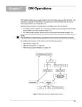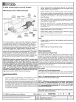
1
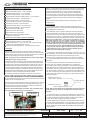
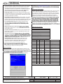
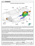
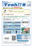
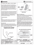
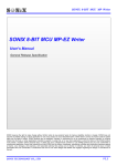
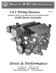
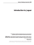
LS Series Crate Engine Control System
40 gph @ 400 kPa for LS2/LS3/LS376s and Minimum 50 gph @
400 kPa for the LSX454 & LS7s.
Thank you for choosing Chevrolet Performance as your high
performance source. Chevrolet Performance is committed to providing
proven, innovative performance technology that is truly.... more than just
power. Chevrolet Performance parts are engineered, developed and
our catalog for the Chevrolet Performance Authorized Center nearest
you or visit our website at www.chevyperformance.com.
Ensure battery voltage is connected using a minimum 8 gauge wire to
one of the studs on the fuse block.
Ensure that the accelerator pedal clearances meet the guidelines
below.
Don’t:
Change or alter any wiring in the accelerator pedal or electronic
throttle systems.
This control system is a stand alone, fully-integrated kit designed to
run Chevrolet Performance Parts LS Series crate engines with 58x
crankshaft reluctor wheels, 4x camshaft indexing, and electronic throttle
control (ETC) - typically 2006 and newer. Included in the kit are the
Vacuum reference the fuel system, it must run constant
400 kPa (60 psi).
Solder or alter any Oxygen Sensor wiring.
mounting boss, oxygen sensors (2), and oxygen sensor mounting
bosses (2). This control system requires a fuel system which maintains
400 kPa (60 psi) constant pressure and can deliver 40 gph for the
LS2/LS3/LS376s or 50 gph for LSX454 & LS7s. Vehicle performance/
driveability and engine durability may be affected if the correct pressure
IMPORTANT: Read the “System DOs and DON’Ts” section below
before attempting to install the engine and then review again
before attempting start the vehicle. Note that if the engine will
not come off idle after the control system installation, check for
an illuminated MIL (malfunction indicator light, which is located
in the fuse/relay center, sometimes called the “Check Engine
Light” or “Service Engine Soon” light) which indicates stored fault
codes. Check for codes and make any required repairs if the MIL
is illuminated (typically it is a connector issue or a wiring issue),
consult a service manual if necessary (Use information from
Chevrolet Performance Parts Diagnostics, 2006- 2011 Cadillac CTS,
2006 – 2010 Corvette or 2010-2011 Camaro).
Observe all safety precautions and warnings in the service
manuals when installing this package in any vehicle. Wear eye
protection and appropriate protective clothing. Support the vehicle
securely with jack stands when working under or around it. Use
only the proper tools. Exercise extreme caution when working with
Vehicle Requirements
Vehicle Speed Input - optional
The ECM is programmed and looking for 40 pulses per revolution
typical for automatic transmissions. The LS Control System harness
is designed to plug into the output speed sensor of 4L60 & 4L80
Transmissions, which have a 40 pulse output. NOTE: If you are using
the CP Supermatic Connect and Cruise Transmission Control
System, the vehicle speed input must be plugged in.
The axle drive ratio in the calibration is set to 3.42:1 and is okay for
ratio from 3.08 to 4.11. Tire diameter needs to be between 26” and 30”.
within the recommended range.
NOTE:
purchased separately and is up to the end user.
See www.chevyperformance.com for recommended CP clutches and
Also see the CP Catalog or www.chevyperformance.com for
.
NOTE: The parts listed here may have been updated or
superseded, go to www.chevyperformance.com for the latest part
number list.
procedures require special equipment and skills. If you do not have
the appropriate training, expertise, and tools to perform any part of Parts List:
this conversion safely, this work should be done by a professional.
These instructions cover the following packages:
System DOs and DON’Ts:
19258553
LS7 Controller Kit for all years
Do:
(Supercedes 19166567 & 19243066)
19166568
LS2 Controller Kit
connecting ignition or battery power to the system.
19258267
LS376/480 Controller Kit (Supersedes 19201327)
19259261
LS376/525 Controller Kit
avoids locations which can potentially damage the wiring (e.g.: sharp
19258270
LS3 Controller Kit (Supersedes 19201861)
edges, pinch points, rotating components, exhaust components, etc.).
19244481
LSX454 Controller Kit
Make sure any unused connectors or wiring are properly secured and
Each Package includes an Engine Control Kit:
protected (sealed or taped as required to avoid short circuiting).
Ensure all engine and wiring harness grounds are clean and secure.
Minimum ¾ inch braided strap from the engine to the vehicle chassis
is recommended.
Each Kit will contain an Engine Control Unit pre-programmed for the
Ensure the MAF sensor is oriented correctly in the induction (it will
only read correctly in the proper direction). An arrow is located on the
mounting boss, as the sensor will mount only one way in the boss.
Ensure the MAF Sensor is mounted in the middle of a minimum 6 inch
length of 4 inch diameter tube, and is a minimum of 10 inches from
the throttle body.
All Engine Control Kits have the following parts:
19171935
I-Sheet (Instruction Sheet)
19166573
Engine Harness
19202597
MAP Sensor Jumper LS3/LS376
-or- 19202598 LS2/LS7/LSX454
Ensure the fuel pressure is a constant 400 kPa (60 psi) with the engine
running. This is what the control system has been developed to run.
TITLE
LS Series Crate Engine Control System
REV 28JN12
ALL INFORMATION WITHIN ABOVE BORDER TO BE PRINTED EXACTLY AS SHOWN ON 8 1/2 x 11
WHITE 16 POUND BOND PAPER. PRINT ON BOTH SIDES, EXCLUDING TEMPLATES.
TO BE UNITIZED IN ACCORDANCE WITH GM SPECIFICATIONS.
10379038
12581966
15156588
DATE
09NO10
28JN12
PART NO.
Accelerator Pedal
Oxygen Sensor - Quantity 2
Oxygen Sensor mounting boss – Quantity 2
19171935
REVISION
Initial Release - William Duncan
Revision - William Duncan
SHEET
1
OF
23
AUTH
Installation Instructions:
Air Cleaner: It is recommended that a dry element air cleaner be used.
NOTE: Fueling cannot be guaranteed if an oiled element type air
cleaner is used.
ECM
The Engine Control Module (ECM) is environmentally sealed and can be
mounted underhood, however, avoid extremely hot locations (exhaust,
Oxygen Sensors: NOTE: It is critical that the Oxygen Sensors are
etc.) or high splash areas. It is not recommended that the EMC be
mounted per the instructions below. The exhaust system MUST be
mounted directly to the engine.
properly sealed – any leak near the sensors (upstream or downstream) can cause incorrect operation of the fuel control system.
Accelerator Pedal
Vehicle performance and/or driveability may be affected if sensors
Mount the accelerator pedal per the following dimensional guidelines,
are not mounted as recommended or if an exhaust leak exists. Leak
check the exhaust system to ensure adequate sealing (even small
that the pedal is securely mounted to the vehicle. A grommet is required leaks can affect fuel control).
in any sheet metal hole that the harness routes through to avoid wire
Oxygen Sensors should be mounted in the collector area of the exdamage.
haust manifolds in a location that allows exhaust from all cylinders to
ACCELERATOR PEDAL ASSEMBLY MINIMUM SPACING GUIDELINES
be sampled equally (stock exhaust manifolds include a mounting boss
for the oxygen sensors). Be sure the connectors and wiring are routed
2.5”
away from high heat areas. The oxygen sensors should be mounted
with the sensor tip pointing between horizontal and fully downward – do
2”
not mount with the tip oriented upward. Weld in the mounting bosses
Brake Pedal Brake
supplied (7/8” hole) if using headers.
Pedal
Accelerator
Pedal
Exhaust Manifolds: It is recommended that you use the provided exhaust manifolds or similar LS Engine style Exhaust Manifolds.
.75”
Accelerator
Pedal
Side View
Positive Crankcase Ventilation System (PCV)
How to set up your PCV system:
There are two ports on the engine that make up the PCV system. The
ports on the engine are:
Tunnel /
Console
Front View
Mass Air Flow (MAF) Sensor
NOTE: It is critical that the MAF sensor is mounted per the
instructions below. Vehicle performance and/or driveability may be
affected if it is not mounted as recommended.
1) Left rear (driver side) valve cover.
2) Top center of the inlet manifold.
The ports with silver tubes may look simple but, they should not be
place of a PCV valve of earlier designs.
the supplied MAF sensor mounting boss. The induction system should
be 4 inches in diameter and have a minimum straight section 6 inches
in length. Mount the MAF sensor in the middle of the straight induction
section, ensuring that the middle of the mounting boss is at least
10 inches from the throttle body.
The MAF sensor must be oriented correctly in the induction
Be sure to weld the mounting boss correctly – the sensor will only
mount one way in the boss (see diagram).
Weld the boss in place before installing the sensor. When installed in
the vehicle, the MAF sensor should be mounted with the connector end
pointing between horizontal and fully upright – do not mount with the
connector oriented downward.
connection must be within the engines air cleaner system and must be
between the MAF (Mass Air Flow Sensor) and engine’s throttle body.
The engine burns the air that enters the PCV system so, if the fresh air
port is prior to the MAF then, this air will enter the engine without being
measured by the MAF and adverse engine operation may occur.
Power Brake Booster Vacuum Source: The vacuum port for the Brake
Booster is a plug in the rear of the intake manifold. If you need the
vacuum source for your brake system the plug needs to be removed and
Oil Pressure Sensor:
pressure sensor you can purchase sensor p/n 12616646 or equivalent.
This is an optional connection and is not required for your control system
to operate.
MAF SENSOR MOUNTING GUIDELINES
MINIMUM 6” STRAIGHT SECTION
4”
TO AIR FILTER
TUBE
There is one fresh air port which is on the front of the right (passenger
side) valve cover. Again this is a silver tube that faces forward on the
MAF SENSOR MOUNTING BOSS
ns
Se
o r M o u nt i
ng
ea
Ar
MA
F
MINIMUM 10” FROM THROTTLE BODY
Engine Wiring Harness: The following lists the engine and vehicle
side connections. Optional circuits are described in the ‘System
Features’ section below: NOTE: A Malfunction Indicator Lamp (MILsometimes called a “service engine soon” light) is mounted inside
the fuse/relay center. A redundant MIL output is also available in
the harness near the pedal module connector. It is recommended
that a MIL also be installed in a visible location in the passenger
compartment. This circuit requires any 12v low current light and
an ignition 12v power source. The ECM MIL output supplies the
ground for the circuit.
UP
TITLE
LS Series Crate Engine Control System
REV 28JN12
ALL INFORMATION WITHIN ABOVE BORDER TO BE PRINTED EXACTLY AS SHOWN ON 8 1/2 x 11
WHITE 16 POUND BOND PAPER. PRINT ON BOTH SIDES, EXCLUDING TEMPLATES.
TO BE UNITIZED IN ACCORDANCE WITH GM SPECIFICATIONS.
DATE
PART NO.
19171935
REVISION
SHEET
2
OF
23
AUTH
Connections Required for Correct Operation
Coolant Sensor – 2 pin Connector
Mass Air Flow (MAF) Sensor – 5 pin Connector
Camshaft Position Sensor – 3 pin Connector
Electronic Throttle Control – 6 pin Connector
Manifold Absolute Pressure (MAP) Sensor – 3 pin Connector
Oxygen Sensors (2 total) – 5 pin Connectors
Knock Sensors (2 total) – 2 pin Connectors
Ignition Coil Blocks (2 total) – 8 pin Connectors
Fuel Injectors (8 total) – 2 pin Connectors
Crankshaft Position Sensor – 3 pin Connector
Accelerator Pedal Sensor – 6 pin Connector
Ignition Switch Input (Wire) Wire
Fuel Pump Control (Wire) Wire
Engine Grounds (3 total) Eyelets
Battery Power (Stud at Fuse/Relay Center)
Cooling Fan Control Wire
Attach a 12 volt ignition switch feed from the vehicle to the pink ignition
switch wire in the harness (this is required to enable the proper powerup sequence of the ECM). This can be routed into the passenger
compartment with the accelerator pedal connector and diagnostic
link connector. Next, connect battery power (minimum 8 gauge wire)
to the horizontal stud on the fuse relay center The other two studs are
for accessories and are 50 amp fused), and the harness installation is
complete.
Additional features and bulkhead connector descriptions are also
included below:
System Features
The Fuse/Relay center contains all required fuses and relays for
proper engine operation. Spare fuse and relay openings are provided
for possible future customer use.
The Fuse/Relay center includes a malfunction indicator light (MIL)
which will illuminate in the event of an engine fault code. See your
Chevrolet Performance Parts dealer to have this code retrieved at the
diagnostic link connector in the fuse/relay center (using a Tech2 with
Chevrolet Performance Parts Diagnostics selection or 2009 CTS LSA
Optional Connections (Not required for operation)
Alternator Control Connector
Engine Oil Pressure Sensor – 3 pin Connector
Vehicle Speed Sensor – 2 pin Connector Only required for CPP
Connect & Cruise Transmission Controls
NOTE: The MIL will illuminate when the vehicle is keyed-up —this
is normal, and it will go out once the engine is started if there are
no current fault codes. A redundant MIL wire is included in the
wiring harness to allow a light to mounted inside the passenger
compartment. The wire is located in the wire bundle near the
pedal connector and the ignition voltage.
Optional User Outputs Bulkhead – 12 pin Connector (12-way)
Connections
Connect all engine/vehicle-side connectors before connecting the
harness to the ECM. All engine/vehicle-side connectors are functionally
labeled, consult a service manual if necessary to determine connection
locations (see following service manual information).
A cooling fan is controlled by the ECM. Control is set to turn on a 12 V
fan at 97 Deg C (207 Deg F) coolant temperature. The fan control wire
is fused/relayed and must be connected directly to your fan.
NOTE: It may be easier to install the harness on the engine before
installing the engine into the vehicle.
The fuel pump is controlled by the ECM. The control wire supplies
12 V and is fused/relayed and should connect to the 12 V side of the
fuel pump.
The harness includes a fuse/relay center containing all required fuses
and relays, and also a 12-way bulkhead connector (with sealed mating
connector) which contains outputs that may be useful to the user (see
‘Bulkhead Connector Outputs’ section below). The fuse/relay center
should be mounted as high in the engine compartment as possible to
avoid unnecessary splash and road debris. Likewise, keep the 12-way
bulkhead connector and diagnostic link connector (both connect from
the fuse/relay center) as high and protected as possible.
A tachometer signal is included in the bulkhead connector (see
below). This is a 2 pulse/rev output which may correspond to
a 4-cylinder setup in some tachometers or transmission controllers.
Note the signal is a low voltage square wave, some tachometers or
transmission controllers may need a pull-up resistor in order to read
the signal, similar to a 5000 ohm, ¼ watt resistor– this detail is left to
the user. The following circuit has worked for numerous devices – the
resister value may need to be changed if your device does not read
this output properly.
The 3 ECM connectors are indexed to connect only in the correct
then pull the top slider bar down until it snaps and locks into place. The
bar should slide easily and will not move unless the connector is seated
properly, do not use excessive force.
Bulkhead Connector Pin C
Engine Speed – Tach Out
Pull High Tach Out
Attach the harness ground eyelets (3 total) to the engine block, ensuring
the connections are clean and secure, and attach the fuel pump wire
from the fuse/relay center to the power side of the pump (this feed is
fused and relay-controlled from the ECM).
Make sure all intended engine and vehicle side connections have
been made before proceeding to connect power.
Main Battery
Connection
Bulkhead Connector Pin L
Ignition Voltage
NOTE: When connected to the CP Supermatic Connect and Cruise
Harness the pull up resister is not required for the Transmission
Controller.
Auxiliary Devices 50 amp fused
An oil pressure output is included in the bulkhead connector and can
be used for a pressure gauge if desired (see below for scaling). If you
are using the optional oil pressure signal in the bulk head connector,
ensure the harness is plugged into oil pressure sensor .
A vehicle speed output is included in the bulkhead connector for use
with auto-scaling speedometers. The vehicle speed sensor connector
in the harness must be attached to a variable reluctance type speed
sensor (typical of most late model GM automatic transmissions) for
this to function.
TITLE
LS Series Crate Engine Control System
REV 28JN12
ALL INFORMATION WITHIN ABOVE BORDER TO BE PRINTED EXACTLY AS SHOWN ON 8 1/2 x 11
WHITE 16 POUND BOND PAPER. PRINT ON BOTH SIDES, EXCLUDING TEMPLATES.
TO BE UNITIZED IN ACCORDANCE WITH GM SPECIFICATIONS.
DATE
PART NO.
19171935
REVISION
SHEET
3
OF
23
AUTH
Oil P
output from the oil pressure sensor which can be used for monitoring
oil pressure (Pressure (psig) = [32*Sensor Voltage]-16). See Chart
Below. Use the ground wire in the bulkhead connector as the low
reference (ground).
Bulkhead Connector Outputs
Bulk Head Connector Pin L
Mating Connector
15326849 Connector
15326854 Connector
12191818 Female Terminal
15304701 Male Connector
15366021 Seal
15366021 Seal
15305171 Plug
15305171 Plug
15430903 TPA
15430903 TPA
15317832 CPA
(32* voltage) -16
Volts
PSI
0.5
0.0
1.0
16.0
2.0
48.0
3.0
80.0
4.0
112.0
5.0
144.0
Throttle Position (PURPLE) - This is an output for use in gauges or for
load indication in transmission controllers (any connection must be to
a high-impedance device). The output is a 0.5 – 4.5 volt signal ranging
from 0 – 100 %. Use the ground wire in the bulkhead connector as the
low reference (ground).
Load View or Rear View
Position
Wire
Gage
2501A
A
22
Tan
GMLAN High Speed (-)
419A
B
22
Brown/White
MIL
121
C
22
White
Engine Speed
818
D
22
Brown
Vehicle Speed - Out
432B
E
22
Lt. Green
MAP Signal
-
F
-
Plug
Empty
2500A
G
22
Tan/Black
GMLAN Low Speed (+)
331B
H
22
Tan/White
Oil Pressure Signal
486B
J
22
Purple
40F
K
18
Orange
Battery Power Fuse
5292
L
18
Pink
Ignition "OnPower
50B
M
18
Black
Ground
Circuit #
PSI =
Color
10A Fused 12V Power (ORANGE) - This is a power output supply and
is always enabled.
Description
15A Fused 12V Ignition Power (PINK) – This is a power output supply
and is enabled only when the ignition is on.
Ground (BLACK) – This is used as the low reference (ground) for
completion of the MAP, TPS, and oil pressure output circuits. It
can also be used for modules connected to either of the fused 12V
outputs.
Terminals for the included mating connector can be acquired at
a GM dealership in the Delphi Terminal Service kit (J38-125) in tray 8
position 9. At most dealerships this can be found at the Service Desk.
Bulkhead connector outputs - Terminals for the included mating
connector can be acquired at a GM dealership in the Delphi Terminal
Service kit. Terminals are Delphi part number 15326269 (GM part
number 19167018), and wire seals are Delphi part number 15366021
(white seal). At many dealerships these can be found at the Service
Desk.
GMLAN Communication Link (TAN/BLACK STRIPE [+], TAN [-]) –
This provides the GMLAN communication messages containing
engine operating parameters for potential use in future add on
modules – any current integration of this is left to the user. Can be
used with a LAN dash or an electronic dash readout display.
NOTE: If you are using CP Supermatic Transmission Controller Kit,
#19212657, the Tachometer Signal (WHITE) and Throttle Position
(PURPLE) are required to be connected. If you are using CP
Supermatic Connect and Cruise Kit, #19257634 or 19257661, the Bulk
Head Connector must be plugged into the CP Supermatic Connect
and Cruise harness. For the Connect and Cruise, the tachometer
signal and the throttle position signal are received through the bulk
head connector.
Start-up and Break-in Procedures
If the vehicle is on the ground, be sure the emergency brake
is set, the wheels are chocked and the car cannot fall into gear. Verify
everything is installed properly and nothing was missed.
1.
Oil & Fluid Fill:
or have oil added. After installing the engine, ensure the crankcase
Tachometer Signal (WHITE) – This is a 2 pulse/rev output (see
features above).
require a special oil meeting GM Standard GM4718M (this will be
Vehicle Speed (BROWN) – This is a non scaled output for use with
auto-scaling speedometers and will not function unless a vehicle
speed sensor (VSS) is connected to the ECM through the VSS wire
in the harness.
However, not all synthetic oils will meet this GM standard. Look for
and use only oil that meets GM Standard GM4718M. Also check
MAP (LT GREEN) – This is an output for use in gauges or for load
indication in transmission controllers (any connection must be to
high-impedance device). The output is a 0-5 Volt signal ranging from
10 – 105 KPa (1.5 – 15.2 psia). Use the ground wire in the bulkhead
connector as the low reference (ground).
TITLE
LS Series Crate Engine Control System
Oil System Prime: a. The engine should be primed with oil
before starting. Install an oil pressure gauge (the existing oil
pressure sensor location at the upper rear of the engine may be
used) and disconnect the engine control system (removing power
from the engine control module is generally recommended).
NOTE: Disconnecting only ignition or fuel injector connectors is
REV 28JN12
ALL INFORMATION WITHIN ABOVE BORDER TO BE PRINTED EXACTLY AS SHOWN ON 8 1/2 x 11
WHITE 16 POUND BOND PAPER. PRINT ON BOTH SIDES, EXCLUDING TEMPLATES.
TO BE UNITIZED IN ACCORDANCE WITH GM SPECIFICATIONS.
2.
DATE
PART NO.
19171935
REVISION
SHEET
4
OF
23
AUTH
not recommended – make sure the control system will not provide
ignition or fuel to the engine. b. Once the engine control system
has been disconnected, crank the engine using the starter for
10 seconds and check for oil pressure. If no pressure is indicated,
wait 30 seconds and crank again for 10 seconds. Repeat this
process until oil pressure is indicated on the gauge.
Appendix: See www.chevyperformance.com for recommended starters,
parts.
How the PCV System Works:
A closed crankcase ventilation system must be used in order to provide
a more complete scavenging of crankcase vapors. Filtered air from
the air induction system (air cleaner) duct is supplied to the crankcase,
mixed with blow-by vapors, and passes through a crankcase ventilation
metering device before entering the intake manifold. The primary
component in the positive crankcase ventilation (PCV) system is the
3.
Initial Engine Start: Reconnect the engine control system. Start
the engine and listen for any unusual noises. If no unusual noises
are noted, run the engine at approximately 1000 RPM until normal
operating temperature is reached.
4.
Engine Warm Up Recommendation: When possible, you should
always allow the engine to warm up prior to driving. It is a good
practice to allow the oil sump and water temperature to reach 180°F
before towing heavy loads or performing hard acceleration runs.
conditions occur, the design of the PCV system permits excessive
First 30 Mile Break-In Period: The engine should be driven
tube and into the engine induction system (air cleaner) to be consumed
during normal combustion. This engine ventilation system design
hour without wide open throttle (WOT) or sustained high RPM
accelerations.
ingestion during vehicle limit handling maneuvers.
6.
Medium Accelerations for Break-In
throttle (50%) accelerations to about 4000 RPM and back to idle
(0% throttle) in gear.
ECM Connectors Pinouts:
7.
Hard Accelerations for Break-In: Run two or three hard throttle
(WOT 100%) accelerations to about 4000 RPM and back to idle
(0% throttle) in gear.
5.
8.
ECM
Blue
Item C1
34576-0703 Connector
Change the Oil and Filter:
33467-0003 Term (22 GA)
33467-0005 Term (18 GA)
9.
that the engine is functioning properly.
34586-0001 Plug
500 Mile Break-In Period: Drive the next 500 miles (12 to
15 engine hours) under normal conditions. Do not run the
engine at its maximum rated engine speed. Also, do not
expose the engine to extended periods of high load.
34575-003 Dress Cover
Circuit #
Pos
Wire Gage
239M
10
22
Pink
Power
10. Change the Oil and Filter after 500 Mile Break-In:
419
12
22
Brown/White
CEL Light
to ensure that the engine is functioning properly.
465
13
22
Green/White
Fuse Bus Pos 7A
239
19
18
Pink
Power
1440
20
22
Red/White
Fuse Bus Pos 6G
121
25
22
White
Engine Speed Bulk Head
Pos C
1164
33
22
White/Black
Pedal Module Pos F
1374
35
22
Red
Pedal Module Pos C
1271
36
22
Brown
Pedal Module Pos D
1272
37
22
Purple
Pedal Module Pos A
818
39
22
Brown
Pin D Bulk Head
Service information
Contact your Chevrolet Performance Parts Dealer for Service or for
instructions on how to obtain Service Manuals and Service Information.
Use information from Chevrolet Performance Parts Diagnostics which
for engine and harness
diagnosis (use this information for all LS Crate Engine Systems).
Color
5069
40
22
Brown
Fuse Bus Pin 1A
PDL 1
47
22
Blue
Pedal Module Pos E
PDL 2
49
22
Lt. Blue
Pedal Module Pos B
473
54
22
Blue
Fuse Bus 7D
All Other Positions to have Cavity Plugs
TITLE
LS Series Crate Engine Control System
REV 28JN12
ALL INFORMATION WITHIN ABOVE BORDER TO BE PRINTED EXACTLY AS SHOWN ON 8 1/2 x 11
WHITE 16 POUND BOND PAPER. PRINT ON BOTH SIDES, EXCLUDING TEMPLATES.
TO BE UNITIZED IN ACCORDANCE WITH GM SPECIFICATIONS.
DATE
PART NO.
19171935
REVISION
SHEET
5
OF
23
AUTH
ECM
Black
Circuit #
Pos
Wire
Gage
Item C2
2123
55
22
Lt. Blue
Odd Coils Pin F
34566-0103 Connector
633
59
22
Brown/White
Cam Sensor Signal Pos C
33467-0003 Terminal (22 GA)
331A
60
22
Tan/White
Oil Pressure Sensor Signal
Pos C
472
62
22
Tan
MAF Pos E
1869
63
22
Blue/White
Crank Sensor Power Pos A
485
64
22
Green
486
66
22
Purple
33467-0005 Terminal (18 GA)
7158-3113-40 Seal (1 each)
7116-4152-02 Term (1 each)
34586-0001 Plug (40 each)
Color
ETC Throttle Pos. Sensor
34565-0003 Dress Cover
ETC Throttle Pos. Sensor
Circuit #
Pos
Wire
Gage
492
67
22
Yellow
MAF Pos A
2121
1
22
Purple
Odd Coil Pin G
3113
68
22
Gray/White
Odd Fr O2 Heater pos E
1664
2
22
Tan
Odd Fr O2 Sensor Pos A
844
70
22
Lt. Blue/Black
Injector 4 Pin B
1665
3
22
Purple/white
Odd Fr O2 Sensor Pos B
877
71
22
Orange/Black
Injector 7 Pin B
1876
6
22
Lt. Blue
Even Knock Pos A
1744
72
22
Tan
Injector 1 Pin B
407
7
22
Tan
Even Knock Pos B
750
73
14
Black
Ground
496
8
22
Blue
Odd Knock Pos A
1716
9
22
Gray
Odd Knock Pos B
581
11
22
Yellow
ETC Pos B
582
12
22
Brown
ETC Pos A
Color
All Other Positions to have Cavity Plugs
ECM
Gray
Item C3
5290
13
18
Pink/Black
Pos 1B Bulk Head
5284
14
22
Purple
Cam Phaser Control Pos D
1746
16
22
Lt. Blue/Black
Injector 3 Pos B
2128
17
22
Purple/white
Even Coils Pos G
2124
18
22
Green/White
Even Coils Pos C
34586-0001 Plug
2130
19
22
Brown/White
Even Coils Pos E
34565-0003 Dress Cover
632
23
22
Pink/Black
Cam Sensor Ground Pos B
2755
24
22
Black
Oil Pressure Sensor Rtn
Pos A
1868
27
22
Yellow/Black
1704
28
22
1704A
29
1745
2127
3466-0203 Connector
33467-0003 Terminal (22 GA)
7158-3113-40 Seal (1 each)
7116-4152-02 Term (1 each)
Circuit #
Pos
Wire Gage
1667
3
22
Tan
Even Fr O2 Pos A
Crank Sensor Ground Pos B
1666
4
22
Purple
Even Fr O2 Pos B
Pink/Black
Fuse Cavity 8J
225
7
22
Orange
Generator Pos B
22
Red/White
ETC Pos C
3212
15
22
Lt. Green
Even Fr O2 Pos E
32
22
Lt. Green/Black
Injector 2 Pin B
469
23
22
Orange/Black
MAP Pos A
33
22
Orange
Odd Coil Pos B
2501
33
22
Tan
ALDL Pin 14
2127A
34
22
Green
Odd Coil Pos C
2761
35
22
Tan
ECT Pos 1
2129
35
22
Brown
Odd Coil Pos E
2704
39
22
Gray
MAP Pos C
631
39
22
Orange
Cam Sensor Power Pos A
335
49
22
Green
Fuse Bus Pos 7D
2500
53
22
Tan/Black
ALDL Pin 6
TITLE
Color
2705
40
22
Gray
Oil Pressure Sensor 5V Ref
Pos B
552
42
22
Tan
MAF Pos D
410
55
22
Yellow
Engine Coolant Sensor
Pos 2
1867
43
22
Lt. green
Crank Sensor Signal Pos C
432
59
22
Lt. Green
MAP Pos B
1688
44
22
Lt. Blue/Black
ETC Pos E
821
66
22
Purple/White
VSS TOSS Hi Pos 2
6753
46
22
Brown
Cam Phaser Low Pin E
822
67
22
48
22
Blue/White
Injector 8 Pin B
Lt. Green/
Black
VSS TOSS Lo Pos 1
878
847
49
22
Tan/White
Injector 5 Pin B
750A
73
14
Black
Ground
846
52
22
Yellow/Black
Injector 6 Pin B
2122
53
22
Red/White
Even Coils Pos B
2126
54
22
Lt. Blue/White
Even Coils Pos F
LS Series Crate Engine Control System
All Other Positions to have Cavity Plugs
REV 28JN12
ALL INFORMATION WITHIN ABOVE BORDER TO BE PRINTED EXACTLY AS SHOWN ON 8 1/2 x 11
WHITE 16 POUND BOND PAPER. PRINT ON BOTH SIDES, EXCLUDING TEMPLATES.
TO BE UNITIZED IN ACCORDANCE WITH GM SPECIFICATIONS.
DATE
PART NO.
19171935
REVISION
SHEET
6
OF
23
AUTH
comprehensive and detailed service practices explained in the GM
service manuals.
The information contained in this publication is presented without any
individual readers are beyond the control of the publisher, and therefore
the publisher disclaims all liability incurred in connection with the use of
the information provided in this publication.
Chevrolet, Chevy, the Chevrolet Bow Tie Emblem, General Motors, and
GM are all registered trademarks of the General Motors Corporation.
TITLE
LS Series Crate Engine Control System
REV 28JN12
ALL INFORMATION WITHIN ABOVE BORDER TO BE PRINTED EXACTLY AS SHOWN ON 8 1/2 x 11
WHITE 16 POUND BOND PAPER. PRINT ON BOTH SIDES, EXCLUDING TEMPLATES.
TO BE UNITIZED IN ACCORDANCE WITH GM SPECIFICATIONS.
DATE
PART NO.
19171935
REVISION
SHEET
7
OF
23
AUTH