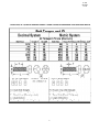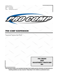
1
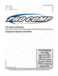
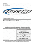
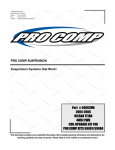
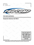
2360 Boswell Road
Chula Vista, CA 91914
Phone
619.216.1444
Fax
619.216.1474
E-Mail
[email protected]
PRO COMP SUSPENSION
Suspension Systems that Work!
Part # LL-1010
1994-2001 Dodge
1500 4wd
1994-2007
Dodge 2500/3500
4wd
2006-2007 Dodge
Ram Mega Cab
1500/2500/3500 4wd
Spacer Kit
This document contains very important information that includes warranty information and instructions for
resolving problems you may encounter. Please keep it in the vehicle as a permanent record.
LL-1010
REVISED
3.17.08
Part #
Description
Qty.
Illus.
Page
90-4007
2” Spring Spacer
2
3
5
90-6060
70-0431251800
73-04300536
Hardware Pack Containing:
7/16” X 1 1/4” USS Gr. 8 Hex Bolt
7/16” Split-Lock Washer
6
6
3
3
5
5
Dodge: 1500
Optional Equipment Available from your Pro Comp Distributor!
PN 56702MX
4WD Suspension Lift Kit
PN 56705MX
2WD Suspension Lift Kit
PN 56701 (Use with Suspension lift kit)
Transfer Case Index Ring Kit
PN 56102 (Use with Suspension lift kit)
Skid Plate
PN 26100
(Black), 26100G (Grey) Hoop Style Light Bar
Also, check out our outstanding selection of Pro Comp tires
compliment your new installation!
Dodge: 2500/3500
Optional Equipment Available from your Pro
56394
56394
56703/56703MX
56708/56708MX
56709 /56709MX
56120
219838
50328
Comp Distributor!
1994-2002 Stage 1 Suspension Lift Kit
1994-2002 Stage 2 Suspension Lift Kit
2003-2008 3” Suspension Lift Kit w/ Coil Spacers
2003-2008 5” Suspension Lift Kit w/ Coil Springs
2003-2008 5” Suspension Lift Kit w/ Coil Spacers
Double Shock Hoop Kit (Use with Suspension lift kit)
Dual Steering Stabilizer Kit
U-bolt kit for vehicles w/ Dana 80 rear axle.
Check out our outstanding selection of Pro Comp tires to
compliment your new installation!
2
LL-1010
REVISED
3.17.08
Introduction:
♦
This installation requires a professional mechanic!
♦ We recommend that you have access to a factory service manual for your vehicle to assist in the
disassembly and reassembly of your vehicle. It contains a wealth of detailed information.
♦
Prior to installation, carefully inspect the vehicle’s steering and driveline systems paying close attention to the tie rod ends, ball joints, wheel bearing preload, pitman and idler arm. Additionally,
check steering-to-frame and suspension-to-frame attaching points for stress cracks. The overall
vehicle must be in excellent working condition. Repair or replace all worn or damaged parts!
♦
Read the instructions carefully and study the illustrations before attempting installation! You may
save yourself a lot of extra work.
♦
Check the parts and hardware against the parts list to assure that your kit is complete. Separating
parts according to the areas where they will be used and placing the hardware with the brackets
before you begin will save installation time.
♦
Check the special equipment list and ensure the availability of these tools.
♦
Secure and properly block vehicle prior to beginning installation.
♦
ALWAYS wear safety glasses when using power tools or working under the vehicle!
♦ Use caution when cutting is required under the vehicle. The factory undercoating is flammable.
Take appropriate precautions. Have a fire extinguisher close at hand.
♦
Foot pound torque readings are listed on the Torque Specifications chart at the end of the instructions. These are to be used unless specifically directed otherwise. Apply thread lock retaining compound where specified.
♦
Please note that while every effort is made to ensure that the installation of your Pro
Comp lift kit is a positive experience, variations in construction and assembly in the
vehicle manufacturing process will virtually ensure that some parts may seem difficult to install. Additionally, the current trend in manufacturing of vehicles results in
a frame that is highly flexible and may shift slightly on disassembly prior to installation. The use of pry bars and tapered punches for alignment is considered normal
and usually does not indicate a faulty product. However, if you are uncertain about
some aspect of the installation process, please feel free to call our tech support department at the number listed on the cover page. We do not recommend that you
modify the Pro Comp parts in any way as this will void any warranty expressed or
implied by the Pro Comp Suspension company.
Please Note:
•
•
•
Front end and head light realignment is necessary!
Speedometer and ABS recalibration will be necessary if larger tires (10% more than stock
diameter) are installed.
Tire and wheel selection is crucial in assuring proper fit performance and the safety
of your Pro Comp equipped vehicle. For this application a wheel not to exceed 8” in
width with a maximum backspacing of 3.5” must be used. Diameter of wheel may be
any of the following 3 choices, 15”,16.5” or 17”. Any other diameter, either smaller
or larger, will not be endorsed as acceptable by Pro Comp Suspension and will void
any and all warranties, written or implied. In addition, a quality tire of radial design,
not to exceed 35” tall x 12.50” wide is recommended. (NOTE: Minor trimming maybe
required when using 35” tall tires).
3
LL-1010
REVISED
3.17.08
5)
Unbolt the shock absorber from the
lower mount bracket on the axle. Remove the shock through the engine compartment. Remove sway bar links and
rotate sway bar down and away. See ILLUSTRATION 1.
INSTRUCTIONS:
Block the rear wheels of the vehicle in front and behind the tires. Raise
the front of the vehicle with a floor jack
and support the frame with jack stands.
Remove the front tires.
1)
6)
Carefully lower the floor jack until
coil springs are free from the upper
spring pocket. Remove the coil springs.
2)
Unbolt both brake line brackets
from the frame to allow for free movement of the suspension components.
Next place an index mark on the bottom
of the coil spring and lower spring pocket.
The coil spring and lower spring mount
can then be installed in the correct position. See ILLUSTRATION 1.
7)
Remove and set aside the upper
rubber isolation pad and the stud ring
from the spring pocket.
(NOTE: You will not be reusing
the stud ring in the installation).
8)
Place the spring spacer, (90-4007),
into the upper spring pocket on the
frame, see ILLUSTRATION 3. Align the
holes with each other. Then loosely bolt
together using 7/16” x 1-1/4” hex bolt
and lock washers. Do not torque down at
this time.
3)
Locate the top shock mount in the
engine compartment. Remove the nut,
retainer and grommet from the shock.
4)
Remove the three nuts from the
upper shock bracket, as shown in ILLUSTRATION 2. Remove the bracket
and set aside.
9)
Illustration 1
Insert the rubber isolator pad in-
Illustration 2
COIL SPRING
SHOCK NUT
RETAINER
GROMMET
SWAY BAR
MOUNTING
BRACKET
EXISTING NUT
SWAY BAR
INDEX MARK
UPPER
SHOCK
BRACKET
GROMMET
SHOCK
RETAINER
UPPER
SPRING
POCKET
COIL
SPRING
4
LL-1010
REVISED
3.17.08
Illustration 3
HEX BOLT,
7/16” x 1 1/4”
7/16” LOCK
WASHER
spring spacer.
SHOCK NUT
12) Insert the shock absorber through
the coil spring from the engine compartment. Install the lower shock bolt and
torque to 75 ft./lbs. See ILLUSTRATION
3.
RETAINER
GROMMET
UPPER
SHOCK
BRACKET
13) Place the upper shock mount
bracket on top of the spring pocket. With
the three holes aligned, reinstall the three
7/16” x 1-1/4” hex bolts and lock washers through the bracket, spring pocket
and into the threaded holes in the spring
spacer. See ILLUSTRATION 3. Torque
to 35 ft./lbs.
GROMMET
RETAINER
SHOCK
UPPER
SPRING
POCKET
14) Install the upper shock mount using the grommet and retainer, fastening
the shock stud and to the shock bracket
with the upper shock nut. See ILLUSTRATION 3.
SPRING
SPACER
#90-4007
EXISTING
RUBBER
ISOLATOR
PAD
15) Repeat on the remaining side of
the vehicle.
16)
Reinstall wheels and lower vehicle.
side the recess of the spring spacer, see
ILLUSTRATION 3.
17) Reattach sway bar links with the
vehicle on the ground.
10) Disconnect track bar at frame
mount and inspect for excessive wear.
The track bar when attached will not allow the front axle to drop down enough to
install spring. Lower axle and install
coils. Be sure the coil is properly indexed.
NOTE:
1)
Have your vehicle aligned to factory specifications.
2)
Check the torque on all fasteners after the first 100 miles. Periodically inspect the components for tightness. Also check for any damage, especially after off road use.
11) Raise the front axle with the floor
jack so that it compresses the front coil
springs and reattach track bar. Remove
the 7/16” X 1 1/4” hex bolts from the
5
LL-1010
REVISED
3.17.08
6
LL-1010
REVISED
3.17.08
7
Notice to Owner operator, Dealer and Installer:
Vehicles that have been enhanced for off-road performance often have unique handling characteristics due to the
higher center of gravity and larger tires. This vehicle may handle, react and stop differently than many passenger cars or
unmodified vehicles, both on and off–road. You must drive your vehicle safely! Extreme care should always be taken to
prevent vehicle rollover or loss of control, which can result in serious injury or even death. Always avoid sudden sharp turns
or abrupt maneuvers and allow more time and distance for braking! Pro Comp reminds you to fasten your seat belts at all
times and reduce speed! We will gladly answer any questions concerning the design, function, maintenance and correct use
of our products.
Please make sure your Dealer/Installer explains and delivers all warning notices, warranty forms and
instruction sheets included with Pro Comp product.
Application listings in this catalog have been carefully fit checked for each model and year denoted. However, Pro
Comp reserves the right to update as necessary, without notice, and will not be held responsible for misprints, changes or
variations made by vehicle manufacturers. Please call when in question regarding new model year, vehicles not listed by
specific body or chassis styles or vehicles not originally distributed in the USA.
Please note that certain mechanical aspects of any suspension lift product may accelerate ordinary
wear of original equipment components. Further, installation of certain Pro Comp products may void the vehicle’s
factory warranty as it pertains to certain covered parts; it is the consumer’s responsibility to check with their local dealer for
warranty coverage before installation of the lift.
Warranty and Return policy:
Pro Comp warranties its full line of products to be free from defects in workmanship and materials. Pro Comp’s obligation under this warranty is limited to repair or replacement, at Pro Comp’s option, of the defective product. Any and all
costs of removal, installation, freight or incidental or consequential damages are expressly excluded from this warranty. Pro
Comp is not responsible for damages and / or warranty of other vehicle parts related or non-related to the installation of Pro
Comp product. A consumer who makes the decision to modify his vehicle with aftermarket components of any kind will
assume all risk and responsibility for potential damages incurred as a result of their chosen modifications. Warranty coverage does not include consumer opinions regarding ride comfort, fitment and design. Warranty claims can be made directly
with Pro Comp or at any factory authorized Pro Comp dealer.
IMPORTANT! To validate the warranty on this purchase please be sure to mail in the warranty card.
Claims not covered under warranty• Parts subject to normal wear, this includes bushings, bump stops, ball joints, tie rod ends and heim joints
• Discontinued products at Pro Comp’s discretion
• Bent or dented product
• Finish after 90 days
• Leaf or coil springs used without proper bump stops
• Light bulbs
• Products with evident damage caused by abrasion or contact with other items
• Damage caused as a result of not following recommendations or requirements called out in the
installation manuals
• Products used in applications other than listed in Pro Comp’s catalog
• Components or accessories used in conjunction with other manufacturer’s systems
• Tire & Wheel Warranty as per Pro Competition Tire Company policy
• Warranty claims without “Proof of Purchase”
• Pro Comp Pro Runner coil over shocks are considered a serviceable shock with a one-year
warranty against leakage only. Rebuild service and replacement parts will be available and sold
separately by Pro Comp. Contact Pro Comp for specific service charges.
• Pro Comp accepts no responsibility for any altered product, improper installation, lack of or
improper maintenance, or improper use of our products.
E-Mail: [email protected]
Website: www.explorerprocomp.com
Fax: (619) 216-1474
Ph: (619) 216-1444
PLACE
WARRANTY REGISTRATION
NUMBER
HERE: __________________