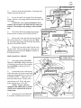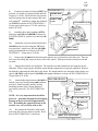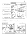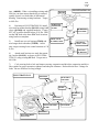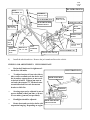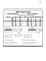
1
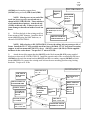
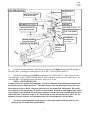
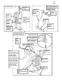
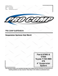
2360 Boswell Road
Chula Vista, CA 91914
Phone
619.216.1444
Fax
619.216.1474
E-Mail
[email protected]
PRO COMP SUSPENSION
Suspension Systems that Work!
Part # 55499
‘97-’02 4WD Jeep
Wrangler TJ
Stage II 3” to 4” Lift
Designed To Fit Vehicles
w/ Power Steering Only
Now Manufactured With
Chromolly Arms
This document contains very important information that includes warranty information and instructions for
resolving problems you may encounter. Please keep it in the vehicle as a permanent record.
55499
Created
4.3.06
Box 1-PN 55499-1
Part #
Description
Qty
90-2058
90-2064
90-1011
90-2065
90-2008
90-2009
90-4002
90-4003
90-6045
90-2002
90-2003
90-6046
45359
600001
60859H
61150
90-6047
90-1003
90-1122
90-2010
90-2014
90-2022
90-2071
JM8
JML8
90-6048
15-11255
90-2310
90-6059
90-1010
90-1121
90-1125
90-6062
70-0503001500
71-1006515008800
70-0372501520
70-0372501500
70-0371501500
70-0371001504
70-0311001500
73-05000030
73-05000036
73-03700030
73-01000036
73-03100030
Lower Control Arm
Crosslink, Track Bar Brace 25.5”
Bracket, Track Bar Mount (Rear)
Brace, Secondary Support 23.75”
Sway Bar Link (Front)
Sway Bar Link (Rear)
Bumpstop Pad (Front)
Bumpstop Extension (Rear)
Hardware Pack Containing:
Transfer Case Pack Spacer, Conical
Spacer, Transfer Case
Hardware Pack & Sleeves
Bushing, (Rubber) Hour Glass
5/8” Urethane Bushing .562 I.D.
Sleeve, 5/8” x 12mm x 1.48” Lg.
Sleeve, 5/8” x 3/8” x 1.48” Lg.
Hardware Pack Containing:
Shifter Drop Bracket
Tab, Track Bar Mount (Pass.)
Sleeve, 7/8” x 1.60” Lg.
Spacer, .750” x .120 Wall x .250”
Sleeve, 3/4” x .87” Lg.
Sleeve, 3/4” x 3.34” Lg.
Rod End w/ Nut, 1/2”-20 Right Hand
Rod End w/ Nut, 1/2”-20 Left Hand
Hardware Pack Containing:
Bushing, Tapered (Red)
Sleeve
Hardware Pack Containing:
Bracket, Sway Bar Front Mount
Frame Brace Mount (Block Mount)
Track Bar Mount (Front)
Hardware Pack Containing:
1/2” x 3” USS Gr. 5 Hex Bolt
10mm x 1.50 x 65mm Hex Bolt
3/8” x 2” Self Tapping Hex Bolt
3/8” x 2 1/2” USS Gr. 5 Hex Bolt
3/8” x 1 1/2” USS Gr. 5 Hex Bolt
3/8” x 1” USS Gr. 5 Hex Bolt
5/16” x 1” USS Gr. 5 Hex Bolt
1/2” SAE Flat Washer
1/2” Split Lock Washer
3/8” SAE Flat Washer
10mm Split Lock Washer
5/16” SAE Flat Washer
2
Illus.
4
1
1
1
2
2
2
2
6,7
8,9,10
20,21
8,9,10
14,15
19
12
18
6
6
16
16
4
4
2
2
14,19
14
14
2
2
1
1
1
1
2
2
17A
9
20
9
10
9
8
8
16
8
6
6
2
1
1
15
9,10
10
7
2
2
2
2
1
3
8
6
12
12
6
55499
Created
4.3.06
72-05000100512
72-03700100512
72-03100100512
71-0602010010909
73-00600040
72-00610008812
90-6066
70-0562751800
70-050751800
70-0502751806
70-0502501800
73-05600042
73-05000038
73-05000030
72-05600100816
72-05000100816
YJ400
1/2” USS Gr. 5 Nyloc Nut
3/8” USS Gr. 5 Nyloc Nut
5/16” USS Gr. 5 Nyloc Nut
6mm x 1.0 x 20mm Button Head
6mm Flat Washer
6mm x 1.0 Nyloc Nut
Hardware Pack Containing:
9/16” x 2 3/4” USS Gr. 8 Hex Bolt
1/2” x 7 1/2” USS Gr. 8 Hex Bolt
1/2” x 2 3/4” USS Ctr. Sunk Allen Bolt
1/2” x 2 1/2” USS Gr. 8 Hex Bolt
9/16” USS Hardened Flat Washer
1/2” Flat Washer A.N.
1/2” SAE Flat Washer
9/16” USS Gr. C Top Lock Nut
1/2” USS Gr. C Top Lock Nut
Pitman Arm (Power Steering Only)
1
5
3
4
8
4
1
1
2
1
1
4
1
4
1
11
FOLLOWING PARTS ARE USED IN CONJUNCTION WITH THIS KIT. THEY ARE NOT
INCLUDED AND MUST BE ORDERED SEPARATELY.
324515
Shock Absorbers (Front)
2
13
324509
Shock Absorbers (Rear)
2
55497
Coil Springs, pair (Front)
1
13
55498
Coil Springs, pair (Rear)
1
OPTIONAL PRODUCT OFFERED BY PRO COMP FOR YOUR JEEP WRANGLER
55496
Winch Spacer, 1” (Front) - Pair
1
7450
Stainless Steel Brake Line
1
219200
Steering Stabilizer
1
20-65225
Rear Pinion Adjustment Cams
1
PRO COMP NOW OFFERS A FULL LINE OF ALL TERRAIN & MUD TERRAIN TIRES.
CALL YOUR LOCAL DEALER FOR DETAILS.
PLEASE NOTE:
Due to differences in manufacturing, dimensions and inflated measurements, tire
and wheel combinations should be test fit prior to installation. Tire and wheel choice is
crucial in assuring proper fit, performance, and the safety of your Pro Comp equipped
vehicle. For this application, we recommend a wheel not to exceed 10” in width with a
minimum backspacing of 3.25” must be used. Additionally, quality tire of radial design,
not exceeding 33” tall X 12.5” wide is also recommended. Please note that the use of a 33”
X 12.5” tire may require fender modification. Violation of these recommendations will
not be endorsed as acceptable by Pro Comp Suspension and will void any and all warranties either written or implied.
3
55499
Created
4.3.06
Introduction:
♦
♦
♦
♦
♦
♦
♦
♦
♦
♦
♦
This installation requires a professional mechanic!
We recommend that you have access to a factory service manual for your vehicle to assist
in the disassembly and reassembly of your vehicle. It contains a wealth of detailed information.
Prior to installation, carefully inspect the vehicle’s steering and driveline systems paying
close attention to the tie rod ends, ball joints, wheel bearing preload, pitman and idler arm.
Additionally, check steering-to-frame and suspension-to-frame attaching points for stress
cracks. The overall vehicle must be in excellent working condition. Repair or replace all
worn or damaged parts!
Read the instructions carefully and study the illustrations before attempting installation!
You may save yourself a lot of extra work.
Check the parts and hardware against the parts list to assure that your kit is complete.
Separating parts according to the areas where they will be used and placing the hardware
with the brackets before you begin will save installation time.
Check the special equipment list and ensure the availability of these tools.
Secure and properly block vehicle prior to beginning installation.
ALWAYS wear safety glasses when using power tools or working under the vehicle!
Use caution when cutting is required under the vehicle. The factory undercoating is flammable. Take appropriate precautions. Have a fire extinguisher close at hand.
Foot pound torque readings are listed on the Torque Specifications chart at the end of the
instructions. These are to be used unless specifically directed otherwise. Apply thread lock
retaining compound where specified.
Please note that while every effort is made to ensure that the installation of your Pro
Comp lift kit is a positive experience, variations in construction and assembly in the
vehicle manufacturing process will virtually ensure that some parts may seem difficult to install. Additionally, the current trend in manufacturing of vehicles results in
a frame that is highly flexible and may shift slightly on disassembly prior to installation. The use of pry bars and tapered punches for alignment is considered normal
and usually does not indicate a faulty product. However, if you are uncertain about
some aspect of the installation process, please feel free to call our tech support department at the number listed on the cover page. We do not recommend that you
modify the Pro Comp parts in any way as this will void any warranty expressed or
implied by the Pro Comp Suspension company.
There are two special tools needed during disassembly and installation. They may be
purchased through your authorized Jeep dealer.
1) Puller - C-3894-Z
2) Pitman arm remover - C-4150A
4
55499
Created
4.3.06
Installation Instructions:
1)
Raise and support vehicle with jack stands. Support axle with a floor jack. Remove wheels
and tires.
2)
Place reference marks (as shown in ILLUSTRATION 1) on front drive shafts and axle. Disconnect the front drive shaft from axle.
ILLUSTRATION 1
ILLUSTRATION 2
AXLE
ADJUSTMENT BRACKET
ADJUSTMENT CAM-BOLT
FRONT DRIVE SHAFT
REFERENCE MARKS
LOWER
CONTROL
ARM
FRONT
DRIVESHAFT
INDEX MARK
AXLE
AXLE BRACKET
NOTE: If vehicle is equipped with ABS brakes remove sensor wire from the inboard
side of the lower control arm.
3)
Locate adjustment cam-bolts, positioned on front of existing lower control arms. Make an
index mark as shown in ILLUSTRATION 2, for installation reference. Remove lower control arms.
ILLUSTRATION 3
ILLUSTRATION 4
PULLER TOOL
C-3894-A
TRACK BAR
PITMAN ARM
FRAME
BRACKET
FRONT AXLE
DRAG LINK
5
55499
Created
4.3.06
ILLUSTRATION 5
4)
Remove front shock absorbers. Disconnect the
stabilizer bar link at the axle.
STEERING GEAR
PITMAN
5)
Lower axle until coil spring is free from upper
ARM
mount. Remove coil spring retainer bolt and remove the
coil spring.
CAUTION: Use a universal Puller Tool to
separate the track bar ball stud from the frame rail
bracket. This will prevent damage to the ball stud
seal.
ILLUSTRATION 6
6)
Disconnect the front track bar at the upper
BUSHING
frame bracket as shown in ILLUSTRATION 3.
15-11255
SPECIAL
TOOL
C-4150-A
WRENCH
SLEEVE 90-2310
7)
Remove the cotter pin and nut from the drag
link at the pitman arm. Using the puller (C-3894A), disconnect the pitman arm from the drag link as
shown in ILLUSTRATION 4.
8)
Remove the nut and washer from the steering gear shaft. Remove pitman arm using special
pitman arm removal tool (C-4150A) as shown in
ILLUSTRATION 5.
LOWER
CONTROL
ARM
90-2058
Long End To Axle
INSTALLATION - FRONT:
ILLUSTRATION 7
1)
Insert the bushing (15-11255)
and sleeve (90-2310), using a thin layer
of lubricant, into the new lower control
arms (90-2058) as shown in ILLUSTRATION 6.
EXISTING HARDWARE
2)
Position the lower control arms
in the front and rear brackets and install
using the existing hardware as shown in
ILLUSTRATION 7. Adjust the cambolt to the index mark. Torque lower
cam-bolt nut to 85 ft./lbs. and upper
frame bracket nut to 110 ft./lbs.
NOTE: If your vehicle is
equipped with ABS brakes re-install
sensor wire to inboard side of lower
control arm.
3)
Referring to ILLUSTRATION
8, assemble crosslink track bar brace
FLAT
WASHER,
5/8”
AS
NEEDED
FRAME MOUNT
FRONT AXLE MOUNT
LOWER CONTROL
ARM 90-2058
6
CAM-BOLT
55499
Created
4.3.06
ILLUSTRATION 8
(90-2064) and secondary support brace
(90-2065) using rod ends (JML8) and (JM8).
ROD END
(RIGHT)
JM8
NOTE: Match groove at one end of the
track bar brace to groove on rod end nut as
shown in ILLUSTRATION 8. These ends have
a left handed thread pattern. Attach rod end
(JLM8) at this end only. Failure to do so will
cause damage to threads on inside of track bar
brace.
CROSSLINK
TRACK BAR
BRACE
(25 1/2”lg.)
90-2064
ROD END
(LEFT)
JML8
BRACE SECONDARY
SUPPORT (23 3/4” LG.)
90-2065
4)
Drill out the hole in the existing track bar
frame mount to 9/16” diameter. Install the block
mount (90-1121) using the 9/16” hardware, as
shown in ILLUSTRATION 9.
GROOVE ON BRACE
AND ROD END NUT
NOTE: Still referring to ILLUSTRATION 9, locate the oblong hole on passenger side of
frame. Install the 25-1/2” long crosslink track bar brace (90-2064), 23-3/4” long brace secondary
support, track bar mount tabs (90-1122), sleeve (90-2071), spacer (90-2014) with the supplied
hardware in the order shown. Torque the 1/2” nut to 85 ft./lbs.
5)
Attach the track bar mount bracket (90-1125) to the block mount (90-1121) using supplied
hardware as shown in ILLUSTRATION 10. Install the opposite ends of the crosslink track bar brace
(90-2064) to the track bar mount bracket (90-1125) and brace secondary support (90-2065) to block
mount (90-1121). Re-connect the existing track bar into the new mounting position using existing
hardware. Torque to 85 ft./lbs.
TAB, TRACK
BAR MOUNT
90-1122
ILLUSTRATION 9
TOP LOCK NUT
1/2” - 13
TOP LOCK NUT,
9/16” - 12
OBLONG HOLE ON
PASSENGER SIDE
SLEEVE, 90-2071
TAB, TRACK
BAR MOUNT
90-1122
DRILL EXISTING
HOLES TO 9/16”
BRACE
SECONDARY
SUPPORT
90-2065
FLAT
WASHER,
9/16”
HEX BOLT,
9/16” x 2 3/4” LG.
SPACER, 90-2014
1/4” THICK
CROSSLINK TRACK
BAR BRACE 90-2064
HEX BOLT,
1/2” x 7 1/2” LG.
7
BLOCK,
MOUNT
90-1121
55499
Created
4.3.06
ILLUSTRATION 10
TOP LOCK NUT
1/2” 13
BRACE SECONDARY
SUPPORT 90-2065
EXISTING
BLOCK, MOUNT
HEX BOLT, 1/2” x 2 1/2”
EXISTING
CROSSLINK TRACK
BAR BRACE 90-2064
TOP LOCK NUT, 1/2” - 13
A.N. FLAT WASHER
1/2”
FLAT HEAD
SOCKET BOLT,
1/2” x 2 3/4”
SLEEVE, 90-2022
EXISTING TRACK BAR
TRACK BAR
MOUNT
90-1125
EXISTING
6)
Using the existing hardware, install the new pitman arm (YJ400) onto the drag link (torque to
60 ft./lbs.) and steering gear shaft (torque to 185 ft./lbs). See ILLUSTRATION 11.
7)
Install new bumpstop pad (90-4002) as shown in ILLUSTRATION 12. Mark center of lower
coil spring pad. Using a 11/32” diameter drill bit, drill a pilot hole in the previously marked area. Install using 3/8” self-tapping hardware provided. torque to 25 ft./lbs.
NOTE: VERY IMPORTANT:
Compress front axle against the bumpstops. Check for clearance between differential and track
bar mount and any related hardware. The block mount, track bar mount bolt allows the track
bar mount to rotate to obtain clearance between track bar mount and differential. Be careful
not to bind rod ends against the side of the track bar mount. Both brace and support bars should
rotate slightly when installed, this will assure adequate clearance between rod ends and brackets.
When clearance is obtained, torque 9/16” block mount to track bar mount bolt to 105 ft./lbs. Inadequate clearance between rod end and bracket will cause premature rod end failure.
⇒
See checks and adjustments on last page for critical information and instructions, concerning track bar mount bolts and hardware.
8
55499
Created
4.3.06
8)
Position new front coil spring (55497) on
axle pad. Re-install coil spring retainer and bolt.
Torque to 16 ft./lbs. Raise the axle into position
until coil spring seats in upper mount, then raise
axle another 2”. Install new longer shock absorbers (324515) as shown in ILLUSTRATION 13.
Torque upper shock nuts to 17 ft./lbs. and lower
nuts to 20 ft./lbs.
ILLUSTRATION 11
CASTLE NUT
PITMAN ARM
YJ400
TO STEERING GEAR
9)
Install the hour glass bushings (45359)
and sleeves (61150) and (60859H) as shown in
ILLUSTRATION 14, into the sway bar link (902008).
COTTER PIN
10)
Mount the sway bar front mount bracket
(90-1010) to the sway bar using the 3/8” hardware provided. Attach sway bar link (90-2008)
using provided hardware as shown in ILLUSTRATION 15. Torque nut to 30 ft./lbs.
DRAG LINK
11)
Remove the (4) 6mm bolts that fasten the transfer case pivot bracket to the floor pan. This can
be accessed by lifting the carpet on drivers side of the vehicle. Slide pivot bracket from pivot rod and
set aside.
12)
Support the transfer case skid plate. The transfer case and transmission are supported by the
skid plate. Before removing the skid plate ensure that the transmission is properly supported. Remove
the (6) bolts connecting the skid plate to the frame. Re-install transfer case skid plate with transfer case
spacers (90-2003), conical spacers (90-2002) and supplied hardware as shown in ILLUSTRATION 16.
Torque bolts to 55 ft./lbs.
13)
Attach shifter drop brackets (90-1003) to
transfer case pivot bracket using 6mm hardware
provided. Install assembly into the existing
mounting location using existing hardware
(previously removed). See ILLUSTRATION
17A.
ILLUSTRATION 12
COIL SPRING
HEX BOLT SELF
TAPING
3/8” x 2” LG.
SPRING
PLATE
NOTE: It is very important that the shifter
pivot rod protrudes through the self-aligning
bearing on the pivot bracket approximately
3/8”. By bending the opposite bracket on the
transfer case, you can easily achieve this.
FLAT WASHER, 3/8”
BUMPSTOP
PAD
90-4002
14)
Re-connect the front drive shaft to the
axle using the reference marks as guides. Refer
back to ILLUSTRATION 1 if necessary.
DRILL 11/32” PILOT HOLE
9
55499
Created
4.3.06
ILLUSTRATION 13
ILLUSTRATION 14
SHOCK
HARDWARE
STOCK
BUMP
STOP
BUSHING, 45359
(FRONT)
SWAY BAR
LINK
90-2008
SHOCK
ABSORBER
324515
FRONT
COIL
SPRING
55497-1
SLEEVE,
61150
(3/8” I.D.)
BUSHING
45359
SLEEVE
60859H
(12mm I.D.)
EXISTING
SPRING RETAINER
ILLUSTRATION 15
NYLOC NUT, 3/8”
FLAT WASHER, 3/8”
HEX
BOLT,
3/8” x 2
1/2” LG.
SWAY BAR FRONT
MOUNT 90-1010
FLAT WASHER, 3/8”
HEX BOLT,
3/8” x 1 1/2”
LG.
NOTE:
Before attaching sway
bar link to axle, rotate
sway bar up and
check for clearance
between the head of
the 3/8 x 2 1/2 bolt and
the side of the frame.
Also be sure the steel
brake line on the top
of the frame does not
interfere with the
sway bar or related
parts.
NYLOC NUT,
3/8”
EXISTING
(FRONT)
SWAY BAR LINK 902008
10
55499
Created
4.3.06
ILLUSTRATION 16
DISASSEMBLY - REAR:
1)
Raise the rear of the vehicle,
support frame with jack stands and
remove rear wheels and tires.
FRAME
TRANSFER
CASE
SPACER,
90-2003
2)
Locate and remove existing
rear lower control arms.
3)
Disconnect lower track bar
mount as shown in ILLUSTRATION 17B.
CONICAL
SPACER
90-2002
4)
Locate and remove rear stabilizer bar and rear shock absorbers.
5)
Lower rear axle until coil
springs are free from upper seat. Remove coil springs.
INSTALLATION - REAR:
TRANSFER CASE
SKID PLATE
FLAT
WASHER,
1/2”
HEX
BOLT,
1/2” x 3”
LG.
SPLIT LOCK
WASHER, 1/2”
1)
Position rear lower control
arms (90-2058) into existing front
and rear mounting brackets and install using hardware previously removed. Do not tighten at this time.
2)
Install new rear bumpstop extensions (90-4003) using the supplied 10mm hardware as shown in
ILLUSTRATION 18. Torque to 27 ft./lbs.
3)
Install rear sway bar links (90-2009) as shown in ILLUSTRATION 19, using hour glass bush-
ILLUSTRATION 17A
SHIFTER DROP BRACKET 90-1003
ILLUSTRATION 17B
EXISTING
TRACK BAR
TRANSFER
CASE
PIVOT
BRACKET
FLAT
WASHER,
6mm
NYLOC NUT
6mm x 1.0
REAR AXLE
BUTTON HEAD BOLT 6mm x 20mm
11
55499
Created
4.3.06
ILLUSTRATION 18
ings (600001). When re-installing existing stabilizer bar you must ensure that the bar is centered,
equally spaced, over both sides of differential
housing. Fasten using existing hardware. Torque
to 40 ft./lbs.
4)
Referring to ILLUSTRATION 20, install
rear track bar mount bracket (90-1011) using 1.60”
sleeve (90-2010) and supplied hardware. Torque
1/2” x 3” track bar bracket bolt to 65 ft./lbs. Drill
out the 3/8” hole at the three 5/16” hole locations
using bracket as template.
5)
Install new rear coil springs (55498) and
new longer shock absorbers (324509). At this
time, torque existing lower control arm nuts to 130
ft./lbs.
FRAME
BUMPSTOP,
EXTENSION
90-4003
BUMPSTOP
RETAINER
SPLIT LOCK
WASHER, 10mm
HEX BOLT,
10mm x 65mm
EXISTING
BUMPSTOP
6)
Attach track bar into new track bar mounting bracket (90-1011), as shown in ILLUSTRATION 21, using existing OE Bolt. Torque nut to
60 ft./lbs.
7)
Cycle steering lock to lock and inspect steering, suspension and driveline suspension and driveline systems for proper operation, tightness and adequate clearance. Recheck brake hose / fittings for
leaks. Be sure all hoses are long enough.
ILLUSTRATION 19
EXISTING
REAR SWAY
BAR LINK
90-2009
BUSHING,
600001
EXISTING
SWAY BAR LINK
90-2009
EXISTING
RETAINER BOLT
SWAY BAR
12
SWAY BAR
55499
Created
4.3.06
ILLUSTRATION 20
FLAT
WASHER, 1/2”
HEX BOLT,
5/16” x 1” LG.
FLAT WASHER, 5/16”
HEX BOLT,
5/16” x 1” LG.
NYLOC NUT, 3/8”
REAR TRACK BAR
MOUNT 90-1011
HEX BOLT,
1/2” x 3” LG.
FLAT
WASHER,
1/2”
SLEEVE (1.60”)
90-2010
NYLOC
NUT,
5/16-18
FLAT
WASHER,
5/16”
8)
HEX BOLT,
3/8” x 1” LG.
NYLOC NUT,
1/2”-13
FLAT
WASHER,
3/8”
FLAT WASHER, 5/16”
NYLOC NUT, 5/16”-18
Install the wheels and tires. Remove the jack stands and lower the vehicle.
CHECKS AND ADJUSTMENTS: VERY IMPORTANT:
⇒
⇒
⇒
⇒
⇒
Recheck all hardware for tightness after the first 100 miles.
ILLUSTRATION 21
To adjust location of front axle (side to
side), rotate crosslink track bar brace and
the secondary support brace to move axle
to desired location. Tighten jam nuts on
rod ends, then torque 1/2” flat head countersunk allen bolts on track bar mount
bracket to 90 ft./lbs.
REAR TRACK BAR
EXISTING
Steering stops can be adjusted by use of
spacers behind welded jam nuts, or be use
of a secondary jam nut (not provided).
Headlights should be adjusted.
Rotate front and rear drive shafts with
suspension hanging. Depending on engine,
AXLE
REAR TRACK BAR
MOUNT 90-1011
13
55499
Created
4.3.06
transmission and differential combinations, it may be necessary to increase the drop on the
transfer case if u-joint-to-yoke interference is found. This can be accomplished with the use
of 1/2” flat washers (not provided). 1/4” additional drop is usually sufficient.
⇒
Alignment of front wheels will be required, use factory specifications.
TORQUE SPECIFICATIONS:
Lower Control Arms-to-Axle..................130 ft./lbs.
Front Shock Absorbers at Axle..............20 ft./lbs.
14
55499
Created
4.3.06
15
Notice to Owner operator, Dealer and Installer:
Vehicles that have been enhanced for off-road performance often have unique handling characteristics due to the
higher center of gravity and larger tires. This vehicle may handle, react and stop differently than many passenger cars or
unmodified vehicles, both on and off–road. You must drive your vehicle safely! Extreme care should always be taken to
prevent vehicle rollover or loss of control, which can result in serious injury or even death. Always avoid sudden sharp turns
or abrupt maneuvers and allow more time and distance for braking! Pro Comp reminds you to fasten your seat belts at all
times and reduce speed! We will gladly answer any questions concerning the design, function, maintenance and correct use
of our products.
Please make sure your Dealer/Installer explains and delivers all warning notices, warranty forms and
instruction sheets included with Pro Comp product.
Application listings in this catalog have been carefully fit checked for each model and year denoted. However, Pro
Comp reserves the right to update as necessary, without notice, and will not be held responsible for misprints, changes or
variations made by vehicle manufacturers. Please call when in question regarding new model year, vehicles not listed by
specific body or chassis styles or vehicles not originally distributed in the USA.
Please note that certain mechanical aspects of any suspension lift product may accelerate ordinary
wear of original equipment components. Further, installation of certain Pro Comp products may void the vehicle’s
factory warranty as it pertains to certain covered parts; it is the consumer’s responsibility to check with their local dealer for
warranty coverage before installation of the lift.
Warranty and Return policy:
Pro Comp warranties its full line of products to be free from defects in workmanship and materials. Pro Comp’s obligation under this warranty is limited to repair or replacement, at Pro Comp’s option, of the defective product. Any and all
costs of removal, installation, freight or incidental or consequential damages are expressly excluded from this warranty. Pro
Comp is not responsible for damages and / or warranty of other vehicle parts related or non-related to the installation of Pro
Comp product. A consumer who makes the decision to modify his vehicle with aftermarket components of any kind will
assume all risk and responsibility for potential damages incurred as a result of their chosen modifications. Warranty coverage does not include consumer opinions regarding ride comfort, fitment and design. Warranty claims can be made directly
with Pro Comp or at any factory authorized Pro Comp dealer.
IMPORTANT! To validate the warranty on this purchase please be sure to mail in the warranty card.
Claims not covered under warranty• Parts subject to normal wear, this includes bushings, bump stops, ball joints, tie rod ends and heim joints
• Discontinued products at Pro Comp’s discretion
• Bent or dented product
• Finish after 90 days
• Leaf or coil springs used without proper bump stops
• Light bulbs
• Products with evident damage caused by abrasion or contact with other items
• Damage caused as a result of not following recommendations or requirements called out in the
installation manuals
• Products used in applications other than listed in Pro Comp’s catalog
• Components or accessories used in conjunction with other manufacturer’s systems
• Tire & Wheel Warranty as per Pro Competition Tire Company policy
• Warranty claims without “Proof of Purchase”
• Pro Comp Pro Runner coil over shocks are considered a serviceable shock with a one-year
warranty against leakage only. Rebuild service and replacement parts will be available and sold
separately by Pro Comp. Contact Pro Comp for specific service charges.
• Pro Comp accepts no responsibility for any altered product, improper installation, lack of or
improper maintenance, or improper use of our products.
E-Mail: [email protected]
Website: www.explorerprocomp.com
Fax: (619) 216-1474
Ph: (619) 216-1444
PLACE
WARRANTY REGISTRATION
NUMBER
HERE: __________________