1
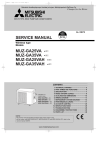
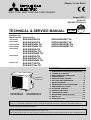
SPLIT-TYPE, HEAT PUMP AIR CONDITIONERS
August 2011
No.OC322
REVISED EDITION-G
HFC
utilized
TECHNICAL & SERVICE MANUAL
R410A
R410A
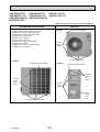
Outdoor unit
[Model names] [Service Ref.]
SUZ-KA25VA
SUZ-KA35VA
SUZ-KA25VAH
SUZ-KA35VAH
SUZ-KA50VA
SUZ-KA60VA
SUZ-KA71VA
SUZ-KA25VA.TH
SUZ-KA35VA.TH
SUZ-KA25VAH.TH
SUZ-KA35VAH.TH
SUZ-KA50VA.TH
SUZ-KA50VA1.TH
SUZ-KA50VAR2.TH
SUZ-KA60VA.TH
SUZ-KA60VA1.TH
SUZ-KA60VAR2.TH
SUZ-KA71VA.TH
SUZ-KA71VA1.TH
SUZ-KA25VAR1.TH
SUZ-KA35VAR1.TH
SUZ-KA25VAHR1.TH
SUZ-KA35VAHR1.TH
CONTENTS
Indication of
model name
SUZ-KA25VA(H).TH
SUZ-KA35VA(H).TH
SUZ-KA25VA(H)R1.TH
SUZ-KA35VA(H)R1.TH
1. COMBINATION OF INDOOR AND OUTDOOR UNITS.... 2
2. TECHNICAL CHANGES ....................................3
3. PART NAMES AND FUNCTIONS......................7
4. SPECIFICATION................................................. 8
5. NOISE CRITERIA CURVES..............................12
6. OUTLINES AND DIMENSIONS........................13
7. WIRING DIAGRAM...........................................15
8. REFRIGERANT SYSTEM DIAGRAM.............. 23
9. PERFORMANCE CURVES.............................. 29
10. ACTUATOR CONTROL.................................... 57
11. SERVICE FUNCTIONS..................................... 58
12. TROUBLESHOOTING...................................... 58
13. DISASSEMBLY INSTRUCTIONS................... 103
14. PARTS LIST.................................................... 113
15. RoHS PARTS LIST......................................... 119
Revision:
• Errors in "11. SERVICE FUNCTIONS" and "12. TROUBLESHOOTING" have been corrected in REVISED EDITION-G.
• Please void OC322 REVISED EDITION-F.
Note:
This service manual describes technical data of the outdoor units.
RoHS compliant products have <G> mark on the spec name plate. For servicing of RoHS compliant products, refer to the RoHS Parts List.
1
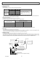
COMBINATION OF INDOOR AND OUTDOOR UNITS
1-1. INDOOR UNIT SERVICE MANUAL
Outdoor unit
Heat pump type
Indoor unit
SUZService Ref.
Service
Manual No.
KA25VA(H).TH KA35VA(H).TH KA50VA(1).TH KA60VA(1).TH KA71VA(1).TH
KA25VA(H)R1.TH KA35VA(H)R1.TH KA50VAR2.TH KA60VAR2.TH
—
SLZ-KA25VA(L).TH
SLZ-KA35VA(L).TH
OC320
Heat pump without electric heater
SEZ-KA50VA.TH
SEZ-KA60VA.TH
—
—
—
SEZ-KA35VA.TH
OC321
SEZ-KA71VA.TH
—
—
—
—
—
—
—
—
—
—
—
—
—
—
—
—
—
—
—
—
—
—
—
—
—
—
—
—
—
—
—
HWE0711
—
—
SEZ-KD25VA(L).TH
SEZ-KD35VA(L).TH
—
—
—
SLZ-KA50VA(L).TH
SEZ-KC25VA.W
—
—
—
—
—
SEZ-KD60VA(L).TH
—
—
—
SEZ-KD71VA(L).TH
—
—
—
—
—
—
—
—
—
—
—
—
—
SEZ-KD50VA(L).TH
MFZ-KA25VA-E1
MFZ-KA35VA-E1
OB409
MFZ-KA50VA-E1
—
—
—
—
(NOTE) • Please refer to the service manual of indoor unit or the technical data book for the combination data.
• Only MFZ-KA·VA series can be connected to SUZ-KA·VAH series.
1-2. TECHNICAL DATA BOOK
OCS03
OC322G
2
2
TECHNICAL CHANGES
SUZ-KA25VA.TH
SUZ-KA25VAH.TH
SUZ-KA35VA.TH
SUZ-KA35VAH.TH
SUZ-KA25VAR1.TH
SUZ-KA25VAHR1.TH
SUZ-KA35VAR1.TH
SUZ-KA35VAHR1.TH
1. Inverter P.C. board and Power P.C. board have been changed.
2. Refrigerant circuit has been changed.
• Compressor has been changed. (KNB073FDVH(C) → KNB073FFDHC : SUZ-KA25VA(H)R1.TH)
(KNB092FCAH
→ KNB092FFAHC : SUZ-KA35VA(H)R1.TH)
• Muffler of liquid pipe side has been deleted.
• Muffler of gas pipe side has been changed.
• Capillary tube of liquid pipe side has been added. (SUZ-KA35VA(H)R1.TH)
• 4-way valve and R.V. coil have been changed.
• Specification of LEV body has been changed.
• Stop valve has been changed.
3. Precharged refrigerant amount has been changed. (900g → 800g : SUZ-KA25VA(H)R1.TH)
4. Fan motor has been changed. (RC0J50-AL → RC0J50-DB)
5. Outdoor heat exchanger temperature thermistor (RT68) has been added.
SUZ-KA50VA1.TH
SUZ-KA60VA1.TH
SUZ-KA50VAR2.TH
SUZ-KA60VAR2.TH
1. OUTDOOR ELECTRONIC CONTROL P.C. BOARD has been changed.
2. Compressor has been changed. (SNB130FLDH(1) → SNB130FGBH)
3. High pressure switch has been added. (SUZ-KA60VAR2.TH)
4. Thermistors (RT61, 62, 64, 65, 68) have been changed. (SUZ-KA50VAR2.TH)
SUZ-KA50VA.TH
SUZ-KA60VA.TH
SUZ-KA71VA.TH
SUZ-KA50VA1.TH
SUZ-KA60VA1.TH
SUZ-KA71VA1.TH
1. OUTDOOR ELECTRONIC CONTROL P.C. BOARD has been changed.
2. Max. height difference 15m → 30m (Except when combined with MFZ).
3. Guaranteed operating range
Lower limit (Cooling/Outdoor) -10:DB → -15:DB (Except when combined with MFZ)
SUZ-KA25VA.TH
SUZ-KA35VA.TH
Lower limit (Heating/Outdoor) -10:DB → -15:DB.
SUZ-KA35VAH.TH
Defrost finish temperature has been changed (Refer to 11. SERVICE FUNCTIONS).
SUZ-A09VR.TH
SUZ-A12VR.TH
SUZ-KA25VA.TH
SUZ-KA35VA.TH
1. Indication of capacity has been changed.(BTU base → kW base)
2. Control method between indoor and outdoor unit has been changed.
3. Power supply method has been changed (change to supply from outdoor unit).
4. Terminal block for power supply has been added.
5. Power P.C. board has been changed.
6. Inverter P.C. board has been changed.
7. Refrigerant circuit has been changed.
• Compressor has been changed. (KNB073FBVH → KNB073FDVH:SUZ-KA25VA) (KNB092FAAH → KNB092FCAH:SUZ-KA35VA)
• Specification and position of muffler have been changed.
• Path of outdoor heat exchanger has been changed.
• 4-way valve and R.V. coil have been changed.
• Stop valve has been changed.
8. Fan motor has been changed. (AC → DC)
9. Shape of grille has been changed.
10. Shape of service panel has been changed.
11. Shape of propeller has been changed.
12. Symbol on terminal block has been changed (to S1/S2/S3).
OC322G
3
SUZ-A18VR
SUZ-A24VR
1.
2.
3.
4.
5.
6.
7.
8.
SUZ-KA50VA.TH
SUZ-KA60VA.TH
Indication of capacity has been changed.(BTU base → kW base)
Power supply method has been changed (change to supply from outdoor unit).
Outdoor electronic control P.C. board has been changed.
Noise filter P.C. board has been changed.
Length of fan motor lead wire has been changed.
Shape of relay panel has been changed.
Symbol on terminal block has been changed (to S1/S2/S3).
Control method between indoor and outdoor unit has been changed.
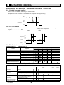
INFORMATION FOR THE AIR CONDITIONER WITH R410A REFRIGERANT
oil
Refrigerant
Refrigerant
• This room air conditioner adopts an HFC refrigerant (R410A) which never destroys the ozone layer.
• Pay particular attention to the following points, though the basic installation procedure is same as that for R22 conditioners.
1 As R410A has working pressure approximate 1.6 times as high as that of R22, some special tools and piping parts/
materials are required. Refer to the table below.
2 Take sufficient care not to allow water and other contaminations to enter the R410A refrigerant during storage and
installation, since it is more susceptible to contaminations than R22.
3 For refrigerant piping, use clean, pressure-proof parts/materials specifically designed for R410A. (Refer to 2. Refrigerant
piping.)
4 Composition change may occur in R410A since it is a mixed refrigerant. When charging, charge liquid refrigerant to prevent
composition change.
Refrigerant
Composition (Ratio)
Refrigerant handling
Chlorine
Safety group (ASHRAE)
Molecular weight
Boiling point ()
Steam pressure [25](Mpa)
Saturated steam density [25](Kg/*)
Combustibility
ODP +1
GWP +2
Refrigerant charge method
Additional charge on leakage
Kind
Color
Smell
+1: Ozone Depletion Potential
+2: Global Warming Potential
OC322G
New refrigerant
R410A
HFC-32: HFC-125 (50%:50%)
Pseudo-azeotropic refrigerant
Not included
A1/A1
72.6
-51.4
1.557
64
Non combustible
0
1730
From liquid phase in cylinder
Possible
Incompatible oil
None
None
: based on CFC-11
: based on CO2
4
Previous refrigerant
R22
R22 (100%)
Single refrigerant
Included
A1
86.5
-40.8
0.94
44.4
Non combustible
0.055
1700
Gas phase
Possible
Compatible oil
Light yellow
None
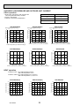
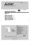
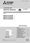
Compressor
New Specification
Current Specification
The incompatible refrigerant oil easily separates from
Since refrigerant and refrigerant oil are compatible with
refrigerant and is in the upper layer inside the suction muffler. each other, refrigerant oil backs to the compressor through
Raising position of the oil back hole enables to back the
the lower position oil back hole.
refrigerant oil of the upper layer to flow back to the
compressor.
Suction muffler
Suction muffler
Oil back hole
Compressor
Compressor
Refrigerant oil
Oil back hole
Refrigerant
Refrigerant oil /Refrigerant
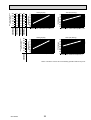
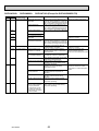
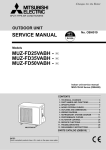
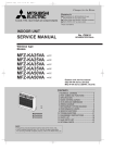
NOTE : The unit of pressure has been changed to MPa on the international system of units (SI unit system).
The conversion factor is: 1 (MPa [Gauge]) =10.2 (kgf/cm2 [Gauge])
Conversion chart of refrigerant temperature and pressure
(MPa [Gauge])
4.0
Saturated liquid pressure
3.5
R410A
3.0
R22
2.5
2.0
NOTE: The unit of pressure has been changed to MPa on the
international system of units (SI unit system).
1.5
1.0
The conversion factor is: 1 (MPa [Gauge]) =10.2 (kgf/cm2 [Gauge])
0.5
0.0
-0.5
-30 -20 -10
0
10
20
30
40
50
60
()
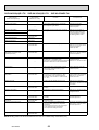
1. Tools dedicated for the air conditioner with R410A refrigerant
The following tools are required for R410A refrigerant. Some R22 tools can be substituted for R410A tools.
The diameter of the service port on the stop valve in outdoor unit has been changed to prevent any other refrigerant being
charged into the unit. Cap size has been changed from 7/16 UNF with 20 threads to 1/2 UNF with 20 threads.
R410A tools
Description
Can R22 tools be used?
Gauge manifold
No
Charge hose
No
Gas leak detector
Torque wrench
R410A has high pressures beyond the measurement range of existing
gauges. Port diameters have been changed to prevent any other refrigerant
from being charged into the unit.
No
Hose material and cap size have been changed to improve the pressure
resistance.
Dedicated for HFC refrigerant.
Yes
6.35 mm and 9.52 mm
No
12.7 mm and 15.88 mm
Flare tool
Yes
Clamp bar hole has been enlarged to reinforce the spring strength in the tool.
Flare gauge
Vacuum pump
adapter
Electronic scale for
refrigerant charging
New
Provided for flaring work (to be used with R22 flare tool).
Provided to prevent the back flow of oil. This adapter enables you to use
vacuum pumps.
It is difficult to measure R410A with a charging cylinder because the
refrigerant bubbles due to high pressure and high-speed vaporization
New
New
No: Not substitutable for R410A
OC322G
Yes: Substitutable for R410A
5
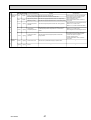
2. Refrigerant piping
1 Specifications
Use the refrigerant pipes that meet the following specifications.
Outside diameter
mm
6.35
9.52
9.52
12.7
15.88
Pipe
For liquid
For gas
Wall thickness
mm
0.8
0.8
0.8
0.8
1.0
Insulation material
Heat resisting foam plastic
Specific gravity 0.045 Thickness
8 mm
• Use a copper pipe or a copper-alloy seamless pipe with a thickness of 0.8 mm. Never use any pipe with a thickness less
than 0.8mm, as the pressure resistance is insufficient.
2 Flaring work and flare nut
Flaring work for R410A pipe differs from that for R22 pipe.
For details of flaring work, refer to Installation manual “FLARING WORK”.
Dimension of flare nut (mm)
Pipe diameter (mm)
R410A
6.35
9.52
12.7
15.88
R22
17
22
24
27
17
22
26
29
3. Refrigerant oil
Apply the special refrigerant oil (accessories: packed with indoor unit) to the flare and the union seat surfaces.
4. Air purge
Do not discharge the refrigerant into the atmosphere.
Take care not to discharge refrigerant into the atmosphere during installation, reinstallation, or repairs to the refrigerant circuit.
Use the vacuum pump for air purging for the purpose of environmental protection.
5. Additional charge
For additional charging, charge the refrigerant from liquid phase of the gas cylinder.
If the refrigerant is charged from the gas phase, composition change may occur in the refrigerant inside the cylinder and the
outdoor unit. In this case, ability of the refrigerating cycle decreases or normal operation can be impossible. However, charging the liquid refrigerant all at once may cause the compressor to be locked. Thus, charge the refrigerant slowly.
Union
Stop valve
Indoor unit
Liquid pipe
Gas pipe
Refrigerant gas
cylinder
operating valve
Outdoor unit
Service port
Gauge manifold
valve (for R410A)
Charge hose (for R410A)
Refrigerant gas cylinder
for R410A with siphon
Refrigerant (liquid)
Electronic scale for refrigerant charging
OC322G
6
3
PART NAMES AND FUNCTIONS
SUZ-KA25VA.TH
SUZ-KA35VA.TH
SUZ-KA25VAH.TH
SUZ-KA35VAH.TH
SUZ-KA25VAR1.TH
SUZ-KA35VAR1.TH
SUZ-KA25VAHR1.TH
SUZ-KA35VAHR1.TH
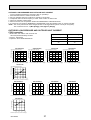
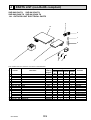
ACCESSORIES
OUTDOOR UNIT
Air inlet
(back and side)
Piping
SUZ-KA25VA.TH
SUZ-KA35VA.TH
SUZ-KA25VAR1.TH
SUZ-KA35VAR1.TH
Drain hose
Air outlet
Drain socket
1
Drain outlet
SUZ-KA50VA.TH SUZ-KA50VA1.TH SUZ-KA50VAR2.TH
SUZ-KA60VA.TH SUZ-KA60VA1.TH SUZ-KA60VAR2.TH
SUZ-KA71VA.TH SUZ-KA71VA1.TH
OUTDOOR UNIT
ACCESSORIES
Air inlet
(back and side)
Piping
Drain hose
Air outlet
Drain outlet
OC322G
7
Drain socket
Drain cap :33
SUZ-KA50VA(1).TH
SUZ-KA60VA(1).TH
SUZ-KA71VA(1).TH
SUZ-KA50VAR2.TH
SUZ-KA60VAR2.TH
1
2
4
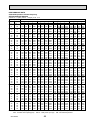
SPECIFICATION
SUZ-KA25VA(H).TH SUZ-KA25VA(H)R1.TH SUZ-KA35VA(H).TH SUZ-KA35VA(H)R1.TH
Outdoor Service Ref.
Function
Special
remarks
Capacity
Fan
motor
Electrical
Compressor data
Power supply
Starting current *1
Compressor motor current *1
Fan motor current *1
Model
Output
Winding
resistance (at 20)
Model
Winding
resistance(at 20)
Air flow(High/Low+)
A
A
A
W
Cooling Heating
Single phase
230V, 50Hz
3.65
2.74
3.37
0.31
0.28
KNB073FDVH(C)
550
U-V 1.53 U-W 1.53
V-W 1.53
RC0J50-AL
WHT-BLK 37.5
BLK-RED 37.5
RED-WHT 37.5
*/h 2,058
1,938
Cooling Heating
Single phase
230V, 50Hz
3.65
2.74
3.37
0.31
0.28
KNB073FFDH(C)
550
U-V 1.70 U-W 1.70
V-W 1.70
RC0J50-DB
WHT-BLK 37.0
BLK-RED 37.0
RED-WHT 37.0
2,058
1,938
SUZ-KA50VA.TH
SUZ-KA50VA1.TH
Cooling Heating
Single phase
230V, 50Hz
4.75
4.22
4.42
0.33
0.33
KNB092FCAH
650
U-V 0.49 U-W 0.49
V-W 0.49
RC0J50-AL
WHT-BLK 37.5
BLK-RED 37.5
RED-WHT 37.5
Cooling Heating
Single phase
230V, 50Hz
4.75
4.22
4.42
0.33
0.33
KNB092FFAH(C)
650
U-V 1.91 U-W 1.91
V-W 1.91
RC0J50-DB
WHT-BLK 37.0
BLK-RED 37.0
RED-WHT 37.0
Cooling Heating
Single phase
230V, 50Hz
6.75
6.45
6.05
0.30
SNB130FLDH or SNB130FLDH1
850
U-V 0.45 U-W 0.45
V-W 0.45
RC0J60-AA
WHT-BLK 15.2
BLK-RED 15.2
RED-WHT 15.2
2,004
2,004
2,940/1,650+ 2,940/2,210+
800%550%285
mm 800%550%285
800%550%285
800%550%285
840%850%330
Dimensions WHD
33
kg
37
33
30
53
Weight
47
47
53/51+ 55/53+
48
48
dB
46
46
Sound level *1
Fan speed(High+/Low+, High+/Med+/Low+) rpm 810+/650+ 880+/810+/650+ 810+/650+ 880+/810+/650+ 840+/760+ 880+/800+/630+ 840+/760+ 880+/800+/630+ 800/480+ 800/620+
2
2
Fan speed regulator
2
2
2
3
3
3
3
Refrigerant filling
1.05
kg
1.05
1.60
0.90
0.80
capacity(R410A)
320 (NEO22) FLDH: 450/FLDH1: 600(NEO22)
320 (NEO22)
320 (NEO22)
320 (NEO22)
Refrigerating oil (Model) cc
NOTE : Test conditions are based on ISO 5151
Cooling : Indoor D.B. 27: W.B. 19:
Outdoor D.B. 35: W.B. 24:
Heating : Indoor D.B. 20: W.B. 15:
Outdoor D.B. 7: W.B. 6:
Refrigerant piping length (one way): 5m
*1 Measured under rated operating frequency.
w Reference value
OC322G
8
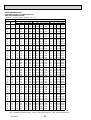
SUZ-KA50VAR2.TH
Outdoor Service Ref.
Function
Special
remarks
Capacity
Fan
motor
Compressor
Electrical
data
Power supply
Starting current *1
Compressor motor current *1
Fan motor current *1
Model
Output
Winding
resistance (at 20)
Model
A
A
A
W
SUZ-KA60VA.TH
SUZ-KA71VA.TH
SUZ-KA60VAR2.TH
SUZ-KA71VA1.TH
SUZ-KA60VA1.TH
Cooling
Heating Cooling Heating Cooling Heating Cooling Heating
Single phase
Single phase
Single phase
Single phase
230V, 50Hz
230V, 50Hz
230V, 50Hz
230V, 50Hz
9.75
9.75
10.30
6.75
9.45
10.00
6.45
9.45
9.60
6.05
8.05
8.05
0.30
0.30
0.30
0.30
TNB220FMCH(T)
SNB130FGBH(T) SNB130FLDH or SNB130FLDH1 SNB130FGBH(T)
850
900
1300
900
U-V 0.98 U-W 0.98 U-V 0.45 U-W 0.45 U-V 0.98 U-W 0.98 U-V 1.41 U-W 1.41
V-W 0.45
V-W 0.98
V-W 1.41
V-W 0.98
RC0J60-AA
RC0J60-AA
RC0J60-AA
RC0J60-AA
WHT-BLK 15.2
WHT-BLK 15.2
WHT-BLK 15.2
WHT-BLK 15.2
BLK-RED
15.2
BLK-RED 15.2
BLK-RED 15.2
BLK-RED 15.2
RED-WHT 15.2
RED-WHT 15.2
RED-WHT 15.2
RED-WHT 15.2
Winding
resistance(at 20)
Air flow(High/Low+)
* /h
2,940/1,650+ 2,940/2,210+ 2,940/1650+ 2,940/2,210+ 2,940/1650+ 2,940/2,210+ 2,940/1650+ 2,940/2,210+
Dimensions WHD
Weight
Sound level *1
Fan speed(High+/Low+, High+/Med+/Low+)
Fan speed regulator
Refrigerant filling
capacity(R410A)
Refrigerating oil (Model)
mm
kg
dB
rpm
840%850%330
840%850%330
840%850%330
840%850%330
53
53
58
53
55/53+ 53/51+
53/51+
53/51+
55/53+
55/53+
55/53+ 53/51+
+
+
+
+
+
+
800/480 800/620 800/480 800/620 800/480+ 800/620 800/480 800/620+
2
2
2
2
kg
1.60
1.80
1.80
2.00
cc
450 (NEO22)
FLDH: 450/FLDH1: 600 (NEO22)
450 (NEO22)
870 (NEO22)
NOTE : Test conditions are based on ISO 5151
Cooling : Indoor D.B. 27: W.B. 19:
Outdoor D.B. 35: W.B. 24:
Heating : Indoor D.B. 20: W.B. 15:
Outdoor D.B. 7: W.B. 6:
Refrigerant piping length (one way): 5m
*1 Measured under rated operating frequency.
w Reference value
OC322G
9
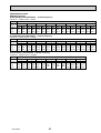
Specifications and rating conditions of main electric parts
SUZ-KA25VA.TH SUZ-KA25VAH.TH
SUZ-KA35VA.TH SUZ-KA35VAH.TH
Model
Item
SUZ-KA25VA.TH
SUZ-KA25VAH.TH
Current transformer
(CT)
Current transformer (CT761, CT781)
Smoothing capacitor (C63A, C63B, C63C)
Diode module
(F61)
Fuse
(F71, F801, F901)
Defrost heater
(H)
ETA19Z59BZ
620420V
D25×B60
250V 20A
250V 3.15A
—
—
230V 130W
Intelligent power module
(IPM)
PS21244-A-203
Expansion valve coil
(LEV)
CAD-MD12ME 12VDC
Reactor
(L61)
10A 23.0mH
Current-detecting resistor
(R61)
Current-detecting resistor
(R831)
25m 5W
Current-limiting resistor (R64A, R64B)
Terminal block
(TB1,TB2)
5.1 5W
Relay
(X63)
G5NB-1a
Relay
(X64)
Relay
(X66)
R.V. coil
45m 5W (1 element)
(26H)
230V 130W
50m 5W (2 elements)
3P
G4A-1A-PS
—
G5NB-1a
—
Open 45
—
G5NB-1a
—
Open 45
STF-01AJ503
(21S4)
Heater protector
SUZ-KA35VAH.TH
ETQ19Z71AY
(DB61, DB65)
Fuse
SUZ-KA35VA.TH
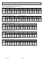
SUZ-KA50VA.TH SUZ-KA50VA1.TH
SUZ-KA60VA.TH SUZ-KA60VA1.TH SUZ-KA60VAR2.TH
SUZ-KA71VA.TH SUZ-KA71VA1.TH
Model
Item
Smoothing capacitor
SUZ-KA60VA.TH
SUZ-KA60VA1.TH
SUZ-KA60VAR2.TH
560 450V
SUZ-KA50VA.TH
SUZ-KA50VA1.TH
(CB1,2,3)
Current transformer
(CT1,2)
ETQ19Z68AY
Current transformer
(CT61)
ETQ19Z53AY
Fuse
(F64)
250V 2A
Fuse
(F801)
250V 3.15A
Fuse
(F911)
250V 1A
Intelligent power module
(HC930)
PS21661-RZ
High pressure switch
(HPS)
Intelligent power module
(IPM)
PS21244-A
(L)
340μH 20A
Reactor
—
ACB-DB156 (for R2)
Expansion valve coil
(LEV)
DC12V
Power factor controller
(PFC)
PS51259-A
Resistor
(R64A,B)
10 10W
Resistor
(R937A,B)
1.1 2W 2%
Resistor
(RS1~4)
0.04 7W
Solenoid coil relay
(SSR61)
TLP3506
Terminal block
(TB1)
3P
Terminal block
(TB2)
3P
Relay
(X64)
G4A
(21S4)
AC 220 - 240V
R.V. coil
OC322G
SUZ-KA71VA.TH
SUZ-KA71VA1.TH
10
ACB-DB156
SUZ-KA25VAR1.TH
SUZ-KA35VAR1.TH
SUZ-KA50VAR2.TH
Item
Current
transformer
Smoothing
capacitor
Diode module
Fuse
Defrost heater
Intelligent power
module
Expansion valve
coil
Reactor
SUZ-KA25VAHR1.TH
SUZ-KA35VAHR1.TH
Model SUZ-KA25VAR1.TH
(CT)
(CT761, CT781)
(C61)
(C62, C63)
(DB61)
(DB65)
(F61)
(F701, F801,
F901)
(H)
OC322G
620 μF 420 V
620 μF 420 V
15 A 600 V
25 A 600 V
T20AL250V
25 A 600 V
T3.15AL250V
—
230 V
130 W
15 A 600 V
(LEV)
DC 12 V
(L61)
45 mΩ 5 W
(1 element)
230 V
130 W
—
(IPM)
—
20 A 600 V
23 mH
100 mΩ 5 W
(2 elements)
—
180 mΩ 5 W
(2 elements)
—
(R61,R62)
(R825)
(R937, R938,
R939)
(R937A, R937B)
Current-limiting
(PTC64,
PTC thermistor
PTC65)
Terminal block
(TB1, TB2)
(X63)
Relay
(X64)
(X66)
R.V. coil
(21S4)
(26H)
Heater protector
IGBT
(TR821)
SUZ-KA35VAHR1.TH SUZ-KA50VAR2.TH
20 A
15 A
—
(R61)
Currentdetecting
resistor
SUZ-KA25VAHR1.TH SUZ-KA35VAR1.TH
25 mΩ 5 W
430 mΩ 2 W
—
—
1.1 Ω 2 W
33 Ω
—
3 A 250 V
—
Open 45°C
11
3P
3 A 250 V
20 A 250 V
—
AC 220 - 240 V
—
30 A 600 V
3 A 250 V
—
Open 45°C
—
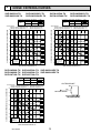
5
NOISE CRITERIA CURVES
SUZ-KA25VAR1.TH
SUZ-KA25VAHR1.TH
SUZ-KA25VA.TH
SUZ-KA25VAH.TH
FAN SPEED FUNCTION
SPL(dB(A))
46
HEATING
46
FAN SPEED FUNCTION
LINE
High
Med.
SPL(dB(A))
COOLING
47
HEATING
48
LINE
Test conditions,
Cooling : Dry-bulb temperature 35Wet-bulb temperature (24)
Heating : Dry-bulb temperature 7Wet-bulb temperature 6
90
Test conditions,
Cooling : Dry-bulb temperature 35Wet-bulb temperature (24)
Heating : Dry-bulb temperature 7Wet-bulb temperature 6
90
OCTAVE BAND SOUND PRESSURE LEVEL, dB re 0.0002 MICRO BAR
COOLING
SUZ-KA35VAR1.TH
SUZ-KA35VAHR1.TH
OCTAVE BAND SOUND PRESSURE LEVEL, dB re 0.0002 MICRO BAR
High
Med.
SUZ-KA35VA.TH
SUZ-KA35VAH.TH
80
70
NC-70
60
NC-60
50
NC-50
40
NC-40
30
NC-30
20
10
APPROXIMATE
THRESHOLD OF
HEARING FOR
CONTINUOUS
NOISE
63
NC-20
125
250
500
1000
2000
4000
8000
80
70
NC-70
60
NC-60
50
NC-50
40
NC-40
30
NC-30
20
10
APPROXIMATE
THRESHOLD OF
HEARING FOR
CONTINUOUS
NOISE
63
BAND CENTER FREQUENCIES, Hz
125
NC-20
250
500
1000
SUZ-KA50VA.TH SUZ-KA50VA1.TH SUZ-KA50VAR2.TH
SUZ-KA60VA.TH SUZ-KA60VA1.TH SUZ-KA60VAR2.TH
SUZ-KA71VA.TH SUZ-KA71VA1.TH
FAN SPEED FUNCTION
High
SPL(dB(A))
COOLING
53
HEATING
55
LINE
OUTDOORUNIT
OCTAVE BAND SOUND PRESSURE LEVEL, dB re 0.0002 MICRO BAR
Test conditions,
Cooling : Dry-bulb temperature 35Wet-bulb temperature (24)
Heating : Dry-bulb temperature 7Wet-bulb temperature 6
90
1m
MICROPHONE
80
70
NC-70
60
NC-60
50
NC-50
40
NC-40
30
NC-30
20
10
APPROXIMATE
THRESHOLD OF
HEARING FOR
CONTINUOUS
NOISE
63
125
NC-20
250
500
1000
2000
4000
8000
BAND CENTER FREQUENCIES, Hz
OC322G
2000
4000
BAND CENTER FREQUENCIES, Hz
12
8000
6
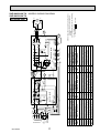
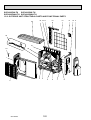
OUTLINES AND DIMENSIONS
SUZ-KA25VA.TH SUZ-KA25VAH.TH SUZ-KA25VAR1.TH SUZ-KA25VAHR1.TH
SUZ-KA35VA.TH SUZ-KA35VAH.TH SUZ-KA35VAR1.TH SUZ-KA35VAHR1.TH
OUTDOOR UNIT
Unit: mm
REQUIRED SPACE
Drain hole :42 (SUZ-KA25/KA35VA)
Drain hole :33 (SUZ-KA25/KA35VAH)
rm
ore
Bolt pitch for
installation
304~325
44
Air in
40
2 holes 10×21
Air out
22.3
re
r mo
mo
m
0
20
Open two sides of left,
right, or rear side.
17.5
23
Service panel
Liquid refrigerant pipe joint
Refrigerant pipe (flared) :6.35
Handle
35
69
Gas refrigerant pipe joint
Refrigerant pipe (flared) :9.52
99.5
10
164.5
280
150
302.5
170.5
Service port
500 Bolt pitch for installation
800
OC322G
43
285
ore
or m
m
m
100
100
mm
o
550
344.5
400
Air in
Basically open 100mm or more
without any obstruction in front
and on both sides of the unit.
13
350
mm
or m
ore
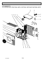
SUZ-KA50VA.TH SUZ-KA50VA1.TH SUZ-KA50VAR2.TH
SUZ-KA60VA.TH SUZ-KA60VA1.TH SUZ-KA60VAR2.TH
SUZ-KA71VA.TH SUZ-KA71VA1.TH
OUTDOOR UNIT
Unit: mm
REQUIRED SPACE
Open as a rule
500mm or more if
the front and both
sides are open
Drain holes :33
515
299
40
100mm or more
200mm or more if
there are obstacles
to both sides
51
34
66
360
330
100mm or more
500
840
121
80
Open as a rule
500mm or more if the back,
both sides and top are open
350mm or more
Service panel
155
90
35
30
430
850
Liquid refrigerant
pipe joint
Refrigerant pipe(flared)
:6.35·····(SUZ-KA50/KA60VA)
:9.52·····(SUZ-KA71VA)
198
OC322G
14
Gas refrigerant
pipe joint
Refrigerant pipe(flared)
:12.7·····(SUZ-KA50VA)
:15.88···(SUZ-KA60/KA71VA)
OC322G
TO INDDOR UNIT
CONNECTING
S3
15
1
2
CN726
CN727
CN721
3
NAME
X63
4
X64
DISCHARGE TEMPERATURE THERMISTOR 21S4
FIN TEMPERATURE THERMISTOR LEV
RT61
RT62
F801,F901 FUSE (T3.15AL250V)
INTELLIGENT POWER DEVICE RT64
AMBIENT TEMPERATURE THERMISTOR
1 2
1 2
CN642
NAME
RT65 RT61 RT62 RT64
CN641
1 2 3 4
CN643
F901
TRANSFORMER
EXPANSION VALVE COIL
REVERSING VALVE COIL
IPM
W
IC932
N
V
U
CN931
1 2 3
CT781
CT761
LEV
CN61
BLK 1
WHT 2
RED 3
6
MF
CN932
CN724
LD-W
LD-U
LD-V
wc
WHT
REDW
BLK
V
U
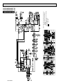
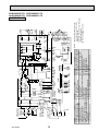
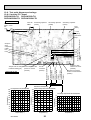
NOTES:1. About the indoor side electric wiring, refer to
the indoor unit electric wiring diagram for
servicing.
2. Use copper conductors only. (For field wiring)
3. Symbols below indicate.
/: Terminal block,
: Connector
1 2 3 4 5
1 2 3 4 5
SWITCHING POWER TRANSISTOR
X63,X64 RELAY
T801
NR63,NR64 VARISTOR
FUSE (T3.15AL250V)
TR821
FUSE (T20AL250V)
IPM,IC932 INTELLIGENT POWER MODULE RT65
IC801
R61
P
INVERTER P.C. BOARD
TR821
F801
T801
TB1,TB2 TERMINAL BLOCK
F71
IC801
LDY
R831
+
R64A,R64B CURRENT-LIMITING RESISTOR
F61
DEFROST THERMISTOR
12 345
CN601
DB65
+
C63A C63B C63C
+
R61,R831 CURRENT-DETECTING RESISTOR
MF
OUTDOOR FAN MOTOR
CN725
TB800
LD69
LD70
DB61
SYMBOL
BLK
SURGE ABSORBER
4
6
21S4
BLU
L61
DSA61
COMPRESSOR
MC
REACTOR
DB61,DB65 DIODE MODULE
SYMBOL
POWER P.C. BOARD
F71
L62,L63 CMC COIL
NAME
WHITE
BLU
RED
LDE
DSA61
NR63
CT
L61
PE
GRN/YLW
GRN
NR64
TAB62
TAB63 BLK
R64B R64A
C63A,C63B,C63C SMOOTHING CAPACITOR
N
L
TB1
RED
L63
CT,CT761,CT781 CURRENT TRANSFORMER
SYMBOL
POWER
SUPPLY
~/N
230V 50Hz
CIRCUIT BREAKER
12-24V
BLU
L62
OUTDOOR UNIT
S2
TB2
F61 WHT TAB61
230V~ S1 WHT
BLK
SUZ-KA25VA.TH
SUZ-KA35VA.TH
GRN
7
WIRING DIAGRAM
MODELS WIRING DIAGRAM
OUTDOOR UNIT
OC322G
NOTES:1. About the indoor side electric wiring, refer to
the indoor unit electric wiring diagram for
servicing.
2. Use copper conductors only. (For field wiring)
3. Symbols below indicate.
: Terminal block
SUZ-KA25VAR1.TH
SUZ-KA35VAR1.TH
16
OC322G
TO INDDOR UNIT
CONNECTING
S3
17
1
2
1
2
L63
SYMBOL
WHITE
REACTOR
LEV
EXPANSION VALVE COIL
BLK
CN725
LD69
TB800
LD70
TR821
IC801
T801
F801
NAME
RT61 RT62
1 2
RT65
CN641
1 2 3 4
CN643
RT64
1 2
CN642
INVERTER P.C. BOARD
LDY
R831
+
C63A C63B C63C
+ +
F901
R61
TRANSFORMER
SWITCHING POWER TRANSISTOR
21S4
HEATER PROTECTOR
DEFROST HEATER
REVERSING VALVE COIL
X63,X64,X66 RELAY
T801
TR821
TB1,TB2 TERMINAL BLOCK
R64A,R64B CURRENT-LIMITING RESISTOR
FIN TEMPERATURE THERMISTOR 26H
AMBIENT TEMPERATURE THERMISTOR
12 345
CN601
DB65
DB61
SYMBOL
DISCHARGE TEMPERATURE THERMISTOR H
R61,R831 CURRENT-DETECTING RESISTOR
IPM,IC932 INTELLIGENT POWER MODULE RT65
INTELLIGENT POWER DEVICE RT64
F801,F901 FUSE (T3.15AL250V)
IC801
RT62
FUSE (T3.15AL250V)
F71
4
6
21S4
DEFROST THERMISTOR
RT61
FUSE (T20AL250V)
F61
CN726
CN727
CN721
L61
BLU
OUTDOOR FAN MOTOR
MF
NR63,NR64 VARISTOR
SURGE ABSORBER
DSA61
3
NAME
X63
4
X64
1
2
TAB63 BLK
R64B R64A
COMPRESSOR
MC
BLU
X66
L62,L63 CMC COIL
RED
1
2
3
CN722
F71
CT
DB61,DB65 DIODE MODULE
BLK
YLW
RED
LDE
DSA61
NR63
L62
POWER P.C. BOARD
NR64
TAB62
TAB61
C63A,C63B,C63C SMOOTHING CAPACITOR
NAME
BLK
BLK
BLK BLK
BLK BLK
GRN/YLW
26H
H
PE
GRN
WHT
L61
N
RED
BLU
F61
CT,CT761,CT781 CURRENT TRANSFORMER
SYMBOL
POWER
SUPPLY
~/N
230V 50Hz
L
CIRCUIT BREAKER TB1
12-24V
S2
WHT
BLK
TB2
IPM
W
V
U
1 2 3
CT781
CT761
LEV
CN61
BLK 1
WHT 2
RED 3
6
MF
CN932
CN724
LD-W
LD-U
LD-V
MC
WHT
RED W
BLK
V
U
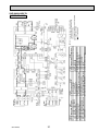
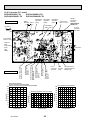
NOTES:1. About the indoor side electric wiring, refer to
the indoor unit electric wiring diagram for
servicing.
2. Use copper conductors only. (For field wiring)
3. Symbols below indicate.
/: Terminal block,
: Connector
1 2 3 4 5
1 2 3 4 5
CN931
IC932
N
P
OUTDOOR UNIT
GRN
230V~ S1
SUZ-KA25VAH.TH MODELS WIRING DIAGRAM
SUZ-KA35VAH.TH
OUTDOOR UNIT
OC322G
NOTES:1. About the indoor side electric wiring, refer to
the indoor unit electric wiring diagram for
servicing.
2. Use copper conductors only. (For field wiring)
3. Symbols below indicate.
: Terminal block
SUZ-KA25VAHR1.TH
SUZ-KA35VAHR1.TH
18
SYMBOL
CB1~3
CT1, 2
CT61
F64
F801
F911
HC930
IPM
L
LEV
PE
NOISE
FILTER
P.C.BOARD
GRN/YLW
N
S3
RED
BLU
WHT
GRN
LDE1
NAME
SMOOTHING CAPACITOR
CURRENT TRANSFORMER
CURRENT TRANSFORMER
FUSE (T2AL 250V)
FUSE (T3.15AL 250V)
FUSE (T1AL 250V)
INTELLIGENT POWER MODULE
INTELLIGENT POWER MODULE
REACTOR
EXPANSION VALVE COIL
12-24V
S2
S1
TO INDOOR
UNIT
CONNECTING
230V~TB2
TAB2
CN61
3
1
BLU
CT61
F911
BRN
WHT
BLU
1 2
F64
RED
SYMBOL
MC
MF
NF
NR64
PFC
R64A,B
R937A, B
RS1~4
RT61
RT62
RT61 RT62
RT65
RED
BLK
BLK
BLK
4 YLW
1
RT68
7 8
LEV
6
CN795
5 6 7
CN702
3
L
S
R
CN4
1 2
1 2
CN701
RS2
RS1
T801
1
LD1
3
RS4
RS3
CT1 U
U
CN932
RED
WHT
BLK
GRN
MF
POWER RT64
BOARD
BLK
WHT
MC
W
RED
V
GRY
PNK
ORN
BLU
YLW
LD9
IPM
V
CT2 W
NOTES: 1. About the indoor side electric wiring,
refer to the indoor unit electric wiring
diagram for servicing.
2. Use copper conductors only (for field wiring).
3. Symbols below indicate.
:Terminal block
:Connector
R937B
R937A
LD2
CB2
NAME
SYMBOL
NAME
COMPRESSOR
RT64 FIN TEMPERATURE THERMISTOR
RT65 AMBIENT TEMPERATURE THERMISTOR
OUTDOOR FAN MOTOR
NOISE FILTER
RT68 OUTDOOR HEAT EXCHANGER
TEMPERATURE THERMISTOR
VARISTOR
SSR61 SOLENOID COIL RELAY
POWER FACTOR CONTROLLER
T801 TRANSFORMER
RESISTOR
TB1 TERMINAL BLOCK
RESISTOR
TB2 TERMINAL BLOCK
RESISTOR
X64 RELAY
DEFROST THERMISTOR
DISCHARGE TEMPERATURE THERMISTOR 21S4 REVERSING VALVE COIL
CN661
1 2 3 4
CN663
1 2
1
ELECTRONIC 1 2 3
5
CONTROL
CN781
P.C.BOARD
21S4
TAB4
CN901
1 2 3
5
NR64
R64A R64B
3
BLK
NF
SSR61
BLK
BLK
BLK
LDE2
CN912
BLU
BLU
CN902 CN903
2 1 2 1
X64
YLW
BLK
L
GRN
3
1
CN601
5
BLK
BLK
BLK
PFC
2 1
CN5
7 6 5 4 3 2 1
CN2
BLK
BLK
F801
CB1
RED
CB3
WHT
CN801
2
HC930
TAB1
CN931
1 2 3 4 5
19
1 2 3
OC322G
CN3
1 2
POWER SUPPLY
~/N 230V 50Hz
CIRCUIT
BREAKER
TB1
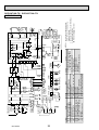
SUZ-KA50VA.TH SUZ-KA50VA1.TH
SUZ-KA60VA.TH SUZ-KA60VA1.TH
OUTDOOR UNIT
3~
MC U
BLK
WHT
RED
1
3
SYMBOL
CT
C61,62,63
DB61,DB65
DSA
F61
F701,F801,F901
HC930,IPM
IC802
L61
L62
W
MS V
RED
LDW
LDV
LDU
U
V
P
N
IPM
W
R825
TR821
1
R61
20
3
MF
MS
3~
CN932
5
3
5
F901
F801
R937A
1
T801
1
RT64
2 1
CN642
HC930
R937B
IC802
L61
RT68
CN644
RT65
RT61 RT62
CN641
4 1
LEV
M
6
CN724
6
CT
LD61
U
F701
LD63
BRN
U
1
CN721
LD-E1
2
F61
LD62
U
LD-S
L62 DSA
PTC65
PTC64
X64
X63
21S4
BRN
BLU
RED
GRN/YLW
BLK
S1
S3
S2
TB2
L
N
TB1
230V~
12-24V
CIRCUIT
BREAKER
NOTES: 1. About the indoor side electric wiring,
NAME
refer to the indoor unit electric wiring
CURRENT-DETECTING RESISTOR
diagram for servicing.
CURRENT-DETECTING RESISTOR
CURRENT-DETECTING RESISTOR
2. Use copper conductors only (for field wiring).
TERMINAL BLOCK
3. Symbols below indicate.
SWITCHING POWER TRANSISTOR
:Terminal block
TRANSFORMER
RELAY
REVERSING VALVE COIL
2 1
SYMBOL
R61
R825
R937A, B
TB1,TB52
TR821
T801
X63,X64
21S4
3 1
CN643
INVERTER P.C. BOARD
YLW
NAME
EXPANSION VALVE COIL
COMPRESSOR
FAN MOTOR
CIRCUIT PROTECTION
DEFROST THERMISTOR
DISCHARGE TEMP. THERMISTOR
FIN TEMP. THERMISTOR
AMBIENT TEMP. THERMISTOR
RT68 OUTDOOR HEAT EXCHANGER
TEMP. THERMISTOR
SYMBOL
LEV
MC
MF
PTC64,PTC65
RT61
RT62
RT64
RT65
CN931
C63 C62 C61
LD66
NAME
CURRENT TRANSFORMER
SMOOTHING CAPACITOR
DIODE MODULE
SURGE ABSORBER
FUSE (T20AL 250V)
FUSE (T3.15AL 250V)
INTELLIGENT POWER MODULE
INTELLIGENT POWER DEVICE
REACTOR
REACTOR
BLK
WHT
1
3
DB65
DB61
LD70
ORN
POWER SUPPLY
~/N 230V 50Hz
TO INDOOR
UNIT
CONNECTING
OC322G
BLU
BRN
SUZ-KA50VAR2.TH
OUTDOOR UNIT
SYMBOL
CB1~3
CT1, 2
CT61
F64
F801
F911
HC930
HPS
IPM
L
NAME
SMOOTHING CAPACITOR
CURRENT TRANSFORMER
CURRENT TRANSFORMER
FUSE (T2AL 250V)
FUSE (T3.15AL 250V)
FUSE (T1AL 250V)
INTELLIGENT POWER MODULE
HIGH PRESSURE SWITCH
INTELLIGENT POWER MODULE
REACTOR
SYMBOL
LEV
MC
MF
NF
NR64
PFC
RS1~4
RT61
RT62
RT64
NAME
EXPANSION VALVE
COMPRESSOR
FAN MOTOR
NOISE FILTER
VARISTOR
POWER FACTOR CONTROLLER
RESISTOR
DEFROST THERMISTOR
DISCHARGE TEMP. THERMISTOR
FIN TEMP. THERMISTOR
SYMBOL
RT65
RT68
R64A,B
R937A, B
SSR61
TB1
TB2
T801
X64
21S4
OUTDOOR UNIT
OC322G
NOTES: 1. About the indoor side electric wiring
NAME
refer to the indoor unit electric wiring
AMBIENT TEMP. THERMISTOR
diagram for servicing.
OUTDOOR HEAT EXCHANGER TEMP. THERMISTOR
RESISTOR
2. Use copper conductors only (for field wiring).
RESISTOR
3. Symbols below indicate.
SOLENOID COIL RELAY
:Terminal block
TERMINAL BLOCK
TERMINAL BLOCK
TRANSFORMER
RELAY
REVERSING VALVE COIL
SUZ-KA60VAR2.TH
21
SYMBOL
CB1~3
CT1, 2
CT61
F64
F801
F911
HC930
HPS
IPM
L
LEV
PE
NOISE
FILTER
P.C.BOARD
GRN/YLW
N
BRN
22
S3
RED
BLU
WHT
NAME
SMOOTHING CAPACITOR
CURRENT TRANSFORMER
CURRENT TRANSFORMER
FUSE (T2AL 250V)
FUSE (T3.15AL 250V)
FUSE (T1AL 250V)
INTELLIGENT POWER MODULE
HIGH PRESSURE SWITCH
INTELLIGENT POWER MODULE
REACTOR
EXPANSION VALVE COIL
12-24V
S2
S1
TO INDOOR
UNIT
CONNECTING
230V~TB2
TAB2
CN61
3
1
WHT
BLU
NF
LDE1
1 2
F64
TAB4
CN901
1 2 3
5
NR64
3
RED
SYMBOL
MC
MF
NF
NR64
PFC
R64A,B
R937A, B
RS1~4
RT61
RT62
RT64
RT61 RT62
CN661
1 2 3 4
RED
BLK
BLK
BLK
4 YLW
1
RT68
7 8
LEV
6
CN795
5 6 7
CN702
3
L
S
R
CN4
1 2
1 2
CN701
RS2
RS1
T801
1
CB2
3
RS3
LD1
RS4
CT1 U
V
U
CN932
RED
WHT
BLK
GRN
MF
POWER RT64
BOARD
BLK
WHT
MC
W
RED
V
GRY
PNK
ORN
BLU
YLW
LD9
IPM
CT2 W
NOTES: 1. About the indoor side electric wiring,
refer to the indoor unit electric wiring
diagram for servicing.
2. Use copper conductors only (for field wiring).
3. Symbols below indicate.
:Terminal block
:Connector
R937B
R937A
LD2
NAME
SYMBOL
NAME
COMPRESSOR
RT65 AMBIENT TEMPERATURE THERMISTOR
OUTDOOR FAN MOTOR
OUTDOOR HEAT EXCHANGER
RT68 TEMPERATURE THERMISTOR
NOISE FILTER
VARISTOR
SSR61 SOLENOID COIL RELAY
POWER FACTOR CONTROLLER
T801 TRANSFORMER
RESISTOR
TB1 TERMINAL BLOCK
TB2 TERMINAL BLOCK
RESISTOR
X64 RELAY
RESISTOR
21S4 REVERSING VALVE COIL
DEFROST THERMISTOR
DISCHARGE TEMPERATURE THERMISTOR
FIN TEMPERATURE THERMISTOR
RT65
CN681 CN663
1 2
1 2
1
21S4
X64
ELECTRONIC 1 2 3
5
CONTROL
CN781
P.C.BOARD
HPS RED
RED
CT61
F911
R64A R64B
SSR61
BLK
BLK
BLK
LDE2
CN912
BLU
BLU
CN902 CN903
2 1 2 1
BLK
BLU
GRN
5
YLW
BLK
L
GRN
3
1
CN601
BLK
BLK
BLK
PFC
2 1
CN5
7 6 5 4 3 2 1
CN2
BLK
BLK
F801
CB1
RED
CB3
WHT
CN801
2
HC930
TAB1
CN931
1 2 3 4 5
1 2 3
OC322G
CN3
1 2
POWER SUPPLY
~/N 230V 50Hz
CIRCUIT
BREAKER
TB1
SUZ-KA71VA.TH SUZ-KA71VA1.TH
OUTDOOR UNIT
8
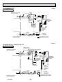
REFRIGERANT SYSTEM DIAGRAM
SUZ-KA25VA.TH
SUZ-KA25VAH.TH
OUTDOOR UNIT
Unit: mm
Refrigerant pipe :9.52
(with heat insulator)
4-way valve
Muffler
Stop valve
(with service port)
Discharge
temperature
thermistor
RT62
Flared connection
Outdoor
heat
exchanger
Muffler
Ambient
temperature
thermistor
RT65
Compressor
Defrost
thermistor
RT61
Strainer
#100
Flared connection
Refrigerant pipe :6.35
(with heat insulator)
LEV
Capillary tube
:3.0×:2.0×240
R.V. coil
heating ON
cooling OFF
Muffler
Stop valve
(with strainer)
Refrigerant flow in cooling
Refrigerant flow in heating
Unit: mm
SUZ-KA25VAR1.TH
SUZ-KA25VAHR1.TH
OUTDOOR UNIT
Refrigerant pipe ø9.52
(with heat insulator)
4-way valve
Muffler
Stop valve
(with service port)
Discharge
temperature
thermistor
RT62
Flared connection
Outdoor
heat
exchanger
Muffler
Outdoor heat
exchanger
temperature
thermistor
RT68
Ambient
temperature
thermistor
RT65
Compressor
Defrost
thermistor
RT61
Flared connection
Refrigerant pipe ø6.35
(with heat insulator)
OC322G
Strainer
#100
Capillary tube
ø3.0×ø2.0×240
Stop valve
(with strainer)
LEV
R.V. coil
heating ON
cooling OFF
Refrigerant flow in cooling
Refrigerant flow in heating
23
SUZ-KA35VA.TH
SUZ-KA35VAH.TH
OUTDOOR UNIT
Unit: mm
Refrigerant pipe :9.52
(with heat insulator)
4-way valve
Muffler
Stop valve
(with service port)
Outdoor
heat
exchanger
Muffler
Discharge
temperature
thermistor
RT62
Flared connection
Ambient
temperature
thermistor
RT65
Compressor
Defrost
thermistor
RT61
Capillary tube
:3.0×:1.8×600(×2)
Strainer
#100
Flared connection
LEV
R.V. coil
heating ON
cooling OFF
Muffler
Refrigerant pipe :6.35
(with heat insulator)
Stop valve
(with strainer)
Refrigerant flow in cooling
Refrigerant flow in heating
SUZ-KA35VAR1.TH
SUZ-KA35VAHR1.TH
OUTDOOR UNIT
Unit: mm
Refrigerant pipe ø9.52
(with heat insulator)
4-way valve
Muffler
Stop valve
(with service port)
Discharge
temperature
thermistor
RT62
Flared connection
Outdoor
heat
exchanger
Muffler
Outdoor heat
exchanger
temperature
thermistor
RT68
Ambient
temperature
thermistor
RT65
Compressor
Defrost
thermistor
RT61
Capillary tube
ø3.0×ø1.8×600(×2)
Flared connection
Refrigerant pipe ø6.35
(with heat insulator)
OC322G
Strainer
#100
Capillary tube
ø3.0×ø2.0×240
LEV
R.V. coil
heating ON
cooling OFF
Stop valve
(with strainer)
Refrigerant flow in cooling
Refrigerant flow in heating
24
SUZ-KA50VA.TH SUZ-KA50VA1.TH
SUZ-KA60VA.TH SUZ-KA60VA1.TH
OUTDOOR UNIT
Refrigerant pipe :12.7 (SUZ-KA50VA)
(with heat insulator) :15.88 (SUZ-KA60VA)
Unit: mm
Muffler
4-way valve #100
Stop valve
(with service port)
Flared connection
Discharge
temperature
thermistor
RT62
Defrost
thermistor
RT61
Outdoor
heat
exchanger
Ambient
temperature
thermistor
RT65
Compressor
Outdoor heat
exchanger
temperature
thermistor
RT68
Flared connection
LEV
Strainer
Receiver #100
Stop valve
Strainer
#100
R.V. coil
heating ON
cooling OFF
Capillary tube
:3.6×:2.4×50
Refrigerant pipe :6.35
(with heat insulator)
Refrigerant flow in cooling
Refrigerant flow in heating
SUZ-KA50VAR2.TH
OUTDOOR UNIT
Unit: mm
Muffler
4-way valve #100
Refrigerant pipe ø12.7
(with heat insulator)
Stop valve
(with service port)
Flared connection
Discharge
temperature
thermistor
RT62
Defrost
thermistor
RT61
Outdoor
heat
exchanger
Ambient
temperature
thermistor
RT65
Compressor
Outdoor heat
exchanger
temperature
thermistor
RT68
Flared connection
LEV
Receiver
Refrigerant pipe ø6.35
(with heat insulator)
Stop valve
(with strainer)
Capillary tube
ø3.6×ø2.4×50
Strainer
#100
R.V. coil
heating ON
cooling OFF
Refrigerant flow in cooling
Refrigerant flow in heating
OC322G
25
SUZ-KA60VAR2.TH
OUTDOOR UNIT
Unit:mm
Refrigerant pipe :15.88
(with heat insulator)
Muffler
4-way valve #100
Stop valve
(with service port)
Flared connection
High-pressure
switch
Discharge
temperature
thermistor
RT62
Defrost
thermistor
RT61
Outdoor
heat
exchanger
Ambient
temperature
thermistor
RT65
Compressor
Outdoor heat
exchanger
temperature
thermistor
RT68
Flared connection
LEV
Strainer
Receiver #100
Stop valve
Refrigerant pipe :6.35
(with heat insulator)
Strainer
#100
Capillary tube
:3.6:2.450
R.V. coil
heating ON
cooling OFF
Refrigerant flow in cooling
Refrigerant flow in heating
Unit:mm
SUZ-KA71VA.TH SUZ-KA71VA1.TH
OUTDOOR UNIT
Refrigerant pipe :15.88
(with heat insulator)
Capillary tube
:1.8×:0.6×1000
Oil separator High-pressure
4-way valve
switch
Stop valve
(with service port)
Strainer
#100
Defrost
thermistor
RT61
Discharge
temperature
thermistor
RT62
Flared connection
Compressor
Flared connection
LEV
Strainer
Receiver #100
Stop valve
Refrigerant pipe :9.52
(with heat insulator)
OC322G
Capillary tube
:3.6×:2.4×50
26
Strainer
#100
Outdoor
heat
exchanger
Ambient
temperature
thermistor
RT65
Outdoor
heat
exchanger
temperature
thermistor
RT68
R.V. coil
heating ON
cooling OFF
Refrigerant flow in cooling
Refrigerant flow in heating
SUZ-KA25VA.TH
SUZ-KA35VA.TH
SUZ-KA25VAH.TH
SUZ-KA35VAH.TH
SUZ-KA25VAR1.TH
SUZ-KA35VAR1.TH
SUZ-KA25VAHR1.TH
SUZ-KA35VAHR1.TH
MAX. REFRIGERANT PIPING LENGTH
Refrigerant piping
Models
Piping size O.D: mm
Max. length: m
SUZ-KA25VA.TH
SUZ-KA35VA.TH
SUZ-KA25VAH.TH
SUZ-KA35VAH.TH
SUZ-KA25VAR1.TH
SUZ-KA35VAR1.TH
SUZ-KA25VAHR1.TH
SUZ-KA35VAHR1.TH
A
Gas
Liquid
20
9.52
6.35
MAX. HEIGHT DIFFERENCE
Indoor
unit
(SLZ/SEZ)
+ Max. Height
difference 12m
Refrigerant Piping
Max. length
A
Outdoor unit
+ Height difference should be within 12m regardless of which unit, indoor or outdoor position is high.
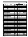
ADDITIONAL REFRIGERANT CHARGE (R410A: g)
Models
Outdoor unit
precharged
SUZ-KA25VA.TH
SUZ-KA25VAH.TH
900
SUZ-KA25VAR1.TH
SUZ-KA25VAHR1.TH
800
SUZ-KA35VA.TH
SUZ-KA35VAH.TH
SUZ-KA35VAR1.TH
SUZ-KA35VAHR1.TH
1,050
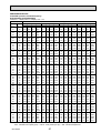
Refrigerant piping length (one way)
5m
6m
7m
8m
9m
10m
11m
12m
13m
14m
15m
20m
0
0
0
90
120
150
180
210
240
270
300
450
0
0
0
90
120
150
180
210
240
270
300
450
Calculation : Xg=30g/m%(Refrigerant piping length(m) - 5)
OC322G
27
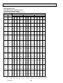
SUZ-KA50VA.TH SUZ-KA50VA1.TH SUZ-KA50VAR2.TH
SUZ-KA60VA.TH SUZ-KA60VA1.TH SUZ-KA60VAR2.TH
SUZ-KA71VA.TH SUZ-KA71VA1.TH
MAX. REFRIGERANT PIPING LENGTH
Refrigerant piping
Model
Piping size O.D: mm
Max. length: m
Liquid
Gas
A
SUZ-KA50VA.TH
SUZ-KA50VA1.TH
SUZ-KA50VAR2.TH
SUZ-KA60VA.TH
SUZ-KA60VA1.TH
SUZ-KA60VAR2.TH
SUZ-KA71VA.TH
SUZ-KA71VA1.TH
12.7
6.35
30
15.88
9.52
MAX. HEIGHT DIFFERENCE
Indoor
unit
(SLZ/SEZ)
+ Max. Height
difference 30m
Refrigerant Piping
Max. length
A
Outdoor unit
+ Height difference should be within 30m regardless of which unit, indoor or outdoor position is high.
Max. Height difference of SUZ-KA50/60/71VA.TH : 15m
SUZ-KA50/60/71VA1.TH : 30m
SUZ-KA50/60VAR2.TH : 30m
ADDITIONAL REFRIGERANT CHARGE (R410A: g)
Refrigerant piping length (one way)
Model
Outdoor unit
precharged
7m
10m
15m
20m
25m
30m
SUZ-KA50VA.TH
SUZ-KA50VA1.TH
SUZ-KA50VAR2.TH
1,600
0
60
160
260
360
460
SUZ-KA60VA.TH
SUZ-KA60VA1.TH
SUZ-KA60VAR2.TH
1,800
0
60
160
260
360
460
Calculation : Xg=20g/m o (Refrigerant piping length(m)–7)
Refrigerant piping length (one way)
Model
Outdoor unit
precharged
7m
10m
15m
20m
25m
30m
SUZ-KA71VA.TH
SUZ-KA71VA1.TH
2,000
0
165
440
715
990
1,265
Calculation : Xg=55g/m o (Refrigerant piping length(m)-7)
OC322G
28
9
PERFORMANCE CURVES
Model
SLZ-KA25VA(L)/SUZ-KA25VA
SLZ-KA35VA(L)/SUZ-KA35VA
SLZ-KA50VA(L)/SUZ-KA50VA
The standard data contained in these specifications applies only to the operation of the air conditioner under normal condition.
Operating conditions vary according to the areas where these units are installed. The following information has been provided
to clarify the operating characteristics of the air conditioner under the conditions indicated by the performance curve.
(1) GUARANTEED VOLTAGE
Rated voltage: ±10% (207~253V), 50Hz
(2) AIR FLOW
Air flow should be set at MAX.
(3) MAIN READINGS
COOLING
HEATING
(1) Indoor intake air wet-bulb temperature: W.B. ˚C (1) Indoor intake air dry-bulb temperature: D.B. ˚C
(2) Indoor outlet air wet-bulb temperature: W.B. ˚C (2) Indoor outlet air dry-bulb temperature: D.B. ˚C
(3) Outdoor intake air dry-bulb temperature: D.B. ˚C (3) Outdoor intake air wet-bulb temperature: W.B. ˚C
(4) Total input: W
(4) Total input: W
Indoor air wet/dry-bulb temperature difference on the side of the chart on page shows the difference between the
indoor intake air wet/dry-bulb temperature and the indoor outlet air wet/dry-bulb temperature for your reference at service.
How to measure the indoor air wet-bulb/dry-bulb temperature difference
1. Attach at least 2 sets of wet-and-dry-bulb thermometers to the indoor air inlet as shown in the figure, and at least 2 sets of
wet-and-dry-bulb thermometers to the indoor air outlet. The thermometers must be attached to the position where air speed
is high.
2. Attach at least 2 sets of wet-and-dry-bulb thermometers to the outdoor air inlet.
Cover the thermometers to prevent direct rays of the sun.
3. Check that the air filter is cleaned.
4. Open windows and doors of the room.
5. Press the EMERGENCY OPERATION switch once to start the EMERGENCY COOL (HEAT) MODE.
6. When system stabilizes after more than 15 minutes, measure temperature and take an average temperature.
7. 10 minutes later, measure temperature again and check that the temperature does not change.
INDOOR UNIT
OUTDOOR UNIT
Wet-and dry-bulb
thermometers
BACK VIEW
OC322G
29
Indoor air Wet-bulb temperature
difference (degree)
Indoor intake air Wet-bulb
temperature()
5.9
5.0
4.5
4.1
-10
-5
0
5
10
15
20
25
30
35
40
45 46
-10
Outdoor intake air Dry-bulb temperature ()
8.4
-5
0
5
10
15
20
25
30
35
40
45 46
Outdoor intake air Dry-bulb temperature ()
Indoor intake air Wet-bulb
temperature()
7.8
Indoor intake air Wet-bulb temperature()
7.2
6.6
6.0
5.4
SUZ-KA35VA(H)
at Rated frequency
-10
-5
0
5
10
15
20
25
30
35
40
45 46
-10
Outdoor intake air Dry-bulb temperature ()
10.8
-5
0
5
10
15
20
25
30
35
40
45 46
Outdoor intake air Dry-bulb temperature ()
Indoor intake air Wet-bulb
temperature()
10.0
Indoor intake air Wet-bulb temperature()
9.2
8.5
7.7
6.9
-15
SUZ-KA50VA
at Rated frequency
Indoor air Wet-bulb temperature
difference (degree)
Indoor intake air Wet-bulb temperature()
5.4
SUZ-KA25VA(H)
at Rated frequency
Indoor air Wet-bulb temperature
difference (degree)
6.4
OC322G
-10
-5
0
5
10
15
20
25
30
35
40
45 46
-15
Outdoor intake air Dry-bulb temperature ()
-10
-5
0
5
10
15
20
25
30
35
Outdoor intake air Dry-bulb temperature ()
30
40
45 46
20.2
23.9
16.0
18.4
21.7
14.4
16.5
19.5
17.4
12.9
15.2
9.6
11.0
13.0
SUZ-KA50VA
at Rated frequency
14.7
11.2
SUZ-KA35VA(H)
at Rated frequency
12.8
)
e(
tur
ra
pe
lb
SUZ-KA25VA(H)
0.0
0
50
100
150(Hz)
The operational frequency of compressor
2.0
Capacity correction factors
1.5
1.0
0.5
0
50
100
150(Hz)
The operational frequency of compressor
SUZ-KA35VA(H)
1.5
1.0
0.5
0.0
0.0
1.5
1.0
0.5
0.0
0
50
100
150(Hz)
The operational frequency of compressor
SUZ-KA50VA
0.5
0.0
0
50
100
150(Hz)
The operational frequency of compressor
0
0.5
1.0
0.5
0.0
0
50
100
150(Hz)
The operational frequency of compressor
1.0
0.5
0.0
0
50
100
150(Hz)
The operational frequency of compressor
150(Hz)
SUZ-KA35VA(H)
2.0
1.5
1.0
0.5
0.0
0
50
100
150(Hz)
The operational frequency of compressor
SUZ-KA50VA
Correction of Heating capacity
1.5
100
Correction of Heating total input
SUZ-KA50VA
2.0
50
The operational frequency of compressor
Correction of Heating capacity
1.0
Correction of Cooling total input
1.5
Input correction factors
1.0
0.0
150(Hz)
1.5
SUZ-KA50VA
Correction of Cooling capacity
1.5
100
0.5
0.0
0
50
100
150(Hz)
The operational frequency of compressor
Capacity correction factors
0.0
0
50
100
150(Hz)
The operational frequency of compressor
2.0
Capacity correction factors
Input correction factors
0.5
50
1.0
SUZ-KA35VA(H)
Correction of Cooling total input
1.5
1.0
0
1.5
The operational frequency of compressor
SUZ-KA35VA(H)
Correction of Cooling capacity
SUZ-KA25VA(H)
Correction of Heating total input
2.0
Correction of Heating capacity
2.0
0.5
Outdoor intake air Wet-bulb temperature ()
SUZ-KA25VA(H)
Correction of Cooling total input
Input correction factors
Capacity correction factors
Ind
u
ry-b
air D
()
NOTE: The above curves are for the heating operation without any frost.
1.5
1.0
ake
int
oor
Outdoor intake air Wet-bulb temperature ()
SUZ-KA25VA(H)
Capacity correction factors
tem
ture
pera
m
lb te
o
Ind
Correction of Cooling capacity
Capacity correction factors
ir
ea
tak
in
or
u
y-b
Dr
Input correction factors
26.0
17.6
Input correction factors
28.2
22.1
2.5
Input correction factors
23.9
19.2
SUZ-KA25VA(H)
at Rated frequency
Indoor air Dry-bulb temperature
difference (degree)
20.8
Correction of Heating total input
2.0
1.5
1.0
0.5
0.0
0
50
100
150(Hz)
The operational frequency of compressor
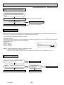
OUTDOOR LOW PRESSURE AND OUTDOOR UNIT CURRENT
<How to operate fixed-frequency operation (Test run operation)>
1. Press the EMERGENCY OPERATION switch or the Test button to COOL or HEAT mode.
2. Test run operation starts and continues to operate for 30 minutes.
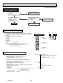
3. Compressor starts at rated frequency in COOL mode or 58Hz in HEAT mode.
4. Indoor fan operates at High speed.
5. After 30 minutes, test run operation finishes and EMERGENCY OPERATION starts.
6. To cancel test run operation (EMERGENCY OPERATION), press the EMERGENCY OPERATION switch or the ON/OFF
button on remote controller.
NOTE : The unit of pressure has been changed to MPa on the international system of units (SI unit system).
The conversion factor is: 1 (MPa [Gauge]) =10.2 (kgf/cm2 [Gauge])
OC322G
31
OUTDOOR LOW PRESSURE AND OUTDOOR UNIT CURRENT
COOL operation
1 Both indoor and outdoor units are under the
same temperature/humidity condition.
2 Air flow : High speed
3 Operation: TEST RUN OPERATION
8
0.8
6
0.6
0.4
4
0.2
15
2
6
0.6
4
2
25
30 32 35(°C)
18 20
50
60
70
(%)
Ambient temperature(°C) Ambient humidity(%)
70
SUZ-KA50VA
12
1.2
10
1.0
8
0.8
6
0.6
0.4
4
0.4
0.2
15
2
0.2
15
25
30 32 35(°C)
18 20
50
60
70
(%)
Ambient temperature(°C) Ambient humidity(%)
SUZ-KA25VA(H)
25
30 32 35(°C)
18 20
50
60
70
(%)
Ambient temperature(°C) Ambient humidity(%)
SUZ-KA35VA(H)
SUZ-KA50VA
5
Outdoor unit current(A)
4
Outdoor unit current(A)
30
3.5
3
2.5
9.0
Outdoor unit current(A)
0.8
60
Outdoor low pressure
1.0
8
25
Outdoor low pressure
Outdoor low pressure
10
1.0
50
(kgf/% [Gauge]) (MPa [Gauge])
14 1.4
1.2
10
20
(kgf/% [Gauge]) (MPa [Gauge])
14 1.4
12
1.2
Relative humidity(%)
SUZ-KA35VA(H)
SUZ-KA25VA(H)
(kgf/% [Gauge]) (MPa [Gauge])
14 1.4
12
Dry-bulb temperature
4.5
4
3.5
3
15
2
15
30 32 35(°C)
25
18 20
70
(%)
50
60
Ambient temperature(°C) Ambient humidity(%)
8.0
7.0
6.0
5.0
15
25
30 32 35(°C)
18 20
50
60
70
(%)
Ambient temperature(°C) Ambient humidity(%)
25
30 32 35(°C)
18 20
50
60
70
(%)
Ambient temperature(°C) Ambient humidity(%)
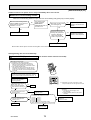
HEAT operation
Condition indoor: Dry bulb temperature 20.0°C
Wet bulb temperature 14.5°C
Condition outdoor: Dry bulb temperature 2,7,15,20.0°C
Wet bulb temperature 1,6,12,14.5°C
SUZ-KA35VA(H)
SUZ-KA50VA
7.0
2.5
3.5
6.0
2.0
1.5
1.0
0.5
0.0
2
5
10
15
20
Ambient temperature(°C)
OC322G
25()
Outdoor unit current (A)
4.0
Outdoor unit current (A)
Outdoor unit current (A)
SUZ-KA25VA(H)
3.0
3.0
2.5
2.0
1.5
1.0
2
5
10
15
20
Ambient temperature(°C)
32
25()
5.0
4.0
3.0
2.0
1.0
2
5
10
15
20
Ambient temperature(°C)
25()
Model
SEZ-KC25VA/SUZ-KA25VA
SEZ-KA35VA/SUZ-KA35VA
SEZ-KA50VA/SUZ-KA50VA
SEZ-KA60VA/SUZ-KA60VA
SEZ-KA71VA/SUZ-KA71VA
The standard data contained in these specifications applies only to the operation of the air conditioner under normal condition.
Operating conditions vary according to the areas where these units are installed. The following information has been provided
to clarify the operating characteristics of the air conditioner under the conditions indicated by the performance curve.
(1) GUARANTEED VOLTAGE
Rated voltage: ±10% (207~253V), 50Hz
(2) AIR FLOW
Air flow should be set at MAX.
(3) MAIN READINGS
COOLING
(1) Indoor intake air wet-bulb temperature: W.B.˚C
(2) Indoor outlet air wet-bulb temperature: W.B.˚C
(3) Outdoor intake air dry-bulb temperature: D.B.˚C
(4) Total input: W
HEATING
(1) Indoor intake air dry-bulb temperature: D.B.˚C
(2) Indoor outlet air dry-bulb temperature:
D.B.˚C
(3) Outdoor intake air wet-bulb temperature: W.B.˚C
(4) Total input: W
Indoor air wet/dry-bulb temperature difference on the side of the chart on page shows the difference between the
indoor intake air wet/dry-bulb temperature and the indoor outlet air wet/dry-bulb temperature for your reference at service.
How to measure the indoor air wet-bulb/dry-bulb temperature difference
1. Attach at least 2 sets of wet-and-dry-bulb thermometers to the indoor air inlet as shown in the figure, and at least 2 sets of
wet-and-dry-bulb thermometers to the indoor air outlet. The thermometers must be attached to the position where air speed
is high.
2. Attach at least 2 sets of wet-and-dry-bulb thermometers to the outdoor air inlet.
Cover the thermometers to prevent direct rays of the sun.
3. Check that the air filter is cleaned.
4. Open windows and doors of the room.
5. Press the TEST button twice to start the COOL (HEAT) MODE.
6. When system stabilizes after more than 15 minutes, measure temperature and take an average temperature.
7. 10 minutes later, measure temperature again and check that the temperature does not change.
INDOOR UNIT
OUTDOOR UNIT
Air outlet
Wet-and dry-bulb
thermometers
Wet-and dry-bulb
thermometers
BACK VIEW
Air inlet
w The picture is SEZ-KA35, 50, 60, 71VA.
SEZ-KC25VA is similar to SEZ-KA35, 50, 60, 71VA.
OC322G
33
Indoor air Wet-bulb temperature
difference (degree)
8.4
Indoor intake air Wet-bulb
temperature()
7.8
7.2
6.6
6.0
5.4
Indoor air Wet-bulb temperature
difference (degree)
SUZ-KA25VA(H)
at Rated frequency
-10
-5
0
5
10
15
20
25
30
35
40
45 46
-10
Outdoor intake air Dry-bulb temperature ()
7.9
-5
0
5
10
15
20
25
30
35
40
45 46
Outdoor intake air Dry-bulb temperature ()
Indoor intake air Wet-bulb
temperature()
7.3
Indoor intake air Wet-bulb temperature()
6.7
6.2
5.6
5.1
-10
-5
0
5
10
15
20
25
30
35
40
45 46
SUZ-KA35VA(H)
at Rated frequency
-10
Outdoor intake air Dry-bulb temperature ()
8.4
8.6
10.5
7.8
8.0
9.6
7.2
7.4
8.8
6.6
6.8
7.9
6.0
6.2
7.1
5.4
5.5
6.3
SUZ-KA71VA
at Rated frequency
SUZ-KA60VA
at Rated frequency
OC322G
-5
0
5
10
15
20
25
30
-10
-5
0
5
10
15
20
35
40
45 46
Outdoor intake air Dry-bulb temperature ()
Indoor intake air Wet-bulb
temperature()
-15
SUZ-KA50VA
at Rated frequency
Indoor air Wet-bulb temperature
difference (degree)
Indoor intake air Wet-bulb temperature()
25
30
35
40
Indoor intake air Wet-bulb temperature()
45 46
-15
Outdoor intake air Dry-bulb temperature ()
34
-10
-5
0
5
10
15
20
25
30
35
Outdoor intake air Dry-bulb temperature ()
40
45 46
24.5
25.3
23.2
20.9
22.6
23.3
21.3
19.2
20.7
21.4
19.4
17.4
18.9
19.4
17.4
15.7
17.0
17.5
15.5
14.0
15.1
15.5
13.6
12.2
13.2
13.6
11.6
10.5
11.3
11.7
SUZ-KA35VA(H)
at Rated frequency
SUZ-KA50VA
at Rated frequency
SUZ-KA60VA
at Rated frequency
Heating capacity
Ind
oo
ri
air
ke
nta
)
e(
tur
a
r
pe
tem
lb
bu
y
Dr
Outdoor intake air Wet-bulb temperature ()
21.4
19.4
17.5
13.6
lb
bu
ir
ea
tak
in
or
yDr
Indo
take
or in
air
)
Outdoor intake air Wet-bulb temperature ()
Total input (heating)
mp
te
re (
ratu
mpe
te
bulb
Dry-
)
(
ure
t
a
er
23.3
15.5
Total input (heating)
Heating capacity
25.3
ake
int
oor
Ind
u
ry-b
air D
ture
pera
m
lb te
()
o
Ind
11.7
SUZ-KA71VA
at Rated frequency
Indoor air Dry-bulb temperature
difference (degree)
22.7
SUZ-KA25VA(H)
at Rated frequency
Indoor air Dry-bulb temperature
difference (degree)
25.2
Outdoor intake air Wet-bulb temperature ()
Outdoor intake air Wet-bulb temperature ()
NOTE: The above curves are for the heating operation without any frost.
OC322G
35
SUZ-KA25VA(H)
Input correction factors
0.5
0.0
0
50
100
150(Hz)
The operational frequency of compressor
0.0
0
50
100
150(Hz)
The operational frequency of compressor
0.5
Capacity correction factors
Input correction factors
2.0
1.0
0.5
Input correction factors
OC322G
1.0
0.5
1.0
0.5
2.0
1.0
0.5
0.0
0.0
0
50
100
150(Hz)
0
50
100
150(Hz)
The operational frequency of compressor
The operational frequency of compressor
36
100
150(Hz)
1.5
1.0
0.5
0.0
0
50
100
150(Hz)
The operational frequency of compressor
SUZ-KA60VA
2.0
Correction of Heating total input
1.5
1.0
0.5
0.0
0
50
100
150(Hz)
The operational frequency of compressor
SUZ-KA71VA
Correction of Heating capacity
1.5
50
Correction of Heating total input
SUZ-KA71VA
1.5
0.0
0
50
100
150(Hz)
The operational frequency of compressor
1.5
Correction of Cooling total input
1.5
0.5
2.0
Correction of Heating capacity
SUZ-KA71VA
SUZ-KA71VA
0.5
SUZ-KA50VA
0.0
0.0
0
50
100
150(Hz)
0
50
100
150(Hz)
The operational frequency of compressor
The operational frequency of compressor
Correction of Cooling capacity
1.0
SUZ-KA60VA
Correction of Cooling total input
1.5
1.0
0.5
SUZ-KA60VA
SUZ-KA60VA
0.0
0
50
100
150(Hz)
The operational frequency of compressor
1.0
150(Hz)
The operational frequency of compressor
Correction of Heating capacity
1.5
100
1.5
0.0
0
Input correction factors
2.0
1.0
Correction of Cooling capacity
0.5
2.0
0.0
0.0
0
50
100
150(Hz)
0
50
100
150(Hz)
The operational frequency of compressor
The operational frequency of compressor
1.5
1.0
0.5
50
Correction of Heating total input
SUZ-KA50VA
Capacity correction factors
Input correction factors
Capacity correction factors
0.5
1.0
SUZ-KA50VA
1.5
1.0
0.5
SUZ-KA35VA(H)
Correction of Heating capacity
1.5
Correction of Cooling total input
1.5
1.0
The operational frequency of compressor
0.0
0.0
0
50
100
150(Hz)
0
50
100
150(Hz)
The operational frequency of compressor
The operational frequency of compressor
SUZ-KA50VA
1.5
0.0
0
Input correction factors
0.5
Correction of Cooling capacity
Capacity correction factors
2.0
1.0
Correction of Heating total input
SUZ-KA35VA(H)
Capacity correction factors
Input correction factors
Capacity correction factors
0.0
0
50
100
150(Hz)
The operational frequency of compressor
0.5
0.0
0
50
100
150(Hz)
The operational frequency of compressor
1.5
0.5
1.0
Correction of Cooling total input
1.5
1.0
1.5
SUZ-KA35VA(H)
SUZ-KA35VA(H)
Correction of Cooling capacity
2.0
Input correction factors
0.0
0
50
100
150(Hz)
The operational frequency of compressor
1.0
SUZ-KA25VA(H)
Correction of Heating capacity
2.0
Input correction factors
0.5
1.5
Capacity correction factors
Capacity correction factors
1.0
2.0
Capacity correction factors
2.0
1.5
Capacity correction factors
SUZ-KA25VA(H)
Correction of Cooling total input
Input correction factors
SUZ-KA25VA(H)
Correction of Cooling capacity
Correction of Heating total input
1.5
1.0
0.5
0.0
0
50
100
150(Hz)
The operational frequency of compressor
OUTDOOR LOW PRESSURE AND OUTDOOR UNIT CURRENT
<How to operate fixed-frequency operation (Test run operation)>
1. Press the TEST button to COOL or HEAT mode.
2. Test run operation starts and continues to operate for 30 minutes.
3. Compressor starts at rated frequency in COOL mode or 58Hz in HEAT mode.
4. Indoor fan operates at High speed.
5. After 30 minutes, test run operation finishes and EMERGENCY OPERATION starts.
6. To cancel test run operation (EMERGENCY OPERATION), press the ON/OFF button on remote controller.
NOTE : The unit of pressure has been changed to MPa on the international system of units (SI unit system).
The conversion factor is: 1 (MPa [Gauge]) =10.2 (kgf/cm2 [Gauge])
OUTDOOR LOW PRESSURE AND OUTDOOR UNIT CURRENT
COOL operation
1 Both indoor and outdoor units are under the
same temperature/humidity condition.
2 Air flow : High speed
3 Operation: TEST RUN OPERATION
20
50
25
60
30
70
(kgf/% [Gauge]) (MPa [Gauge])
14 1.4
(kgf/% [Gauge]) (MPa [Gauge])
14 1.4
Outdoor low pressure
SUZ-KA60VA
(kgf/% [Gauge]) (MPa [Gauge])
14 1.4
Outdoor low pressure
SUZ-KA50VA
(kgf/% [Gauge]) (MPa [Gauge])
14 1.4
Outdoor low pressure
SUZ-KA35VA(H)
Relative humidity(%)
Outdoor low pressure
SUZ-KA25VA(H)
Dry-bulb temperature
12
1.2
10
1.0
12
1.2
10
1.0
8
0.8
6
0.6
8
0.8
6
0.6
4
0.4
2
0.2
15
25
30 32 35(°C)
18 20
50
60
70
(%)
Ambient temperature(°C) Ambient humidity(%)
12
1.2
10
1.0
8
0.8
6
0.6
4
0.4
2
0.2
15
25
30 32 35(°C)
18 20
50
60
70
(%)
Ambient temperature(°C) Ambient humidity(%)
12
1.2
10
1.0
8
0.8
6
0.6
4
0.4
4
0.4
2
0.2
15
2
0.2
15
25
30 32 35(°C)
18 20
50
60
70
(%)
Ambient temperature(°C) Ambient humidity(%)
25
30 32 35(°C)
18 20
50
60
70
(%)
Ambient temperature(°C) Ambient humidity(%)
SUZ-KA71VA
Outdoor low pressure
(kgf/% [Gauge]) (MPa [Gauge])
14 1.4
12
1.2
10
1.0
8
0.8
6
0.6
4
0.4
2
0.2
15
25
30 32 35(°C)
18 20
50
60
70
(%)
Ambient temperature(°C) Ambient humidity(%)
SUZ-KA35VA(H)
3.5
3
2.5
2
15
30 32 35(°C)
25
18 20
70
(%)
50
60
Ambient temperature(°C) Ambient humidity(%)
4.5
4
3.5
3
15
30 32 35(°C)
25
18 20
70
(%)
50
60
Ambient temperature(°C) Ambient humidity(%)
SUZ-KA71VA
Outdoor unit current(A)
12
10
8
6
4
15
30 32 35(°C)
25
18 20
70
(%)
50
60
Ambient temperature(°C) Ambient humidity(%)
OC322G
SUZ-KA60VA
10
Outdoor unit current(A)
Outdoor unit current(A)
Outdoor unit current(A)
SUZ-KA50VA
5
37
9
8
7
6
15
30 32 35(°C)
25
18 20
70
(%)
50
60
Ambient temperature(°C) Ambient humidity(%)
12
Outdoor unit current(A)
SUZ-KA25VA(H)
4
10
8
6
4
15
30 32 35(°C)
25
18 20
70
(%)
50
60
Ambient temperature(°C) Ambient humidity(%)
HEAT operation
Condition indoor: Dry bulb temperature 20.0°C
Wet bulb temperature 14.5°C
Condition outdoor: Dry bulb temperature 2,7,15,20.0°C
Wet bulb temperature 1,6,12,14.5°C
SUZ-KA35VA(H)
SUZ-KA50VA
3.5
3.5
6.0
6.0
3.0
2.5
2.0
1.5
2
5
10
15
20
25()
Ambient temperature(°C)
3.0
2.5
2.0
1.5
1.0
2
5
10
15
20
25()
5.0
4.0
3.0
2.0
1.0
Ambient temperature(°C)
SUZ-KA71VA
12.0
11.0
10.0
9.0
8.0
2
5
10
15
20
25()
Ambient temperature(°C)
OC322G
2
5
10
15
20
Ambient temperature(°C)
13.0
7.0
Outdoor unit current (A)
7.0
Outdoor unit current (A)
7.0
1.0
Outdoor unit current (A)
SUZ-KA60VA
4.0
Outdoor unit current (A)
Outdoor unit current (A)
SUZ-KA25VA(H)
4.0
38
25()
5.0
4.0
3.0
2.0
1.0
2
5
10
15
20
Ambient temperature(°C)
25()
PERFORMANCE DATA
COOLING operation at Rated frequency
SLZ-KA25VA(L)/SUZ-KA25VA(H)
CAPACITY : 2.5(kW) INPUT : 690(W) SHF : 0.86
INDOOR INDOOR
D.B.() W.B.()
18
21
20
21
18
22
20
22
22
22
18
23
20
23
22
23
18
24
20
24
22
24
24
24
20
25
22
25
24
25
18
26
20
26
22
26
24
26
26
26
18
27
20
27
22
27
24
27
26
27
18
28
20
28
22
28
24
28
26
28
18
29
20
29
22
29
24
29
26
29
18
30
20
30
22
30
24
30
26
30
18
31
20
31
22
31
24
31
26
31
18
32
20
32
22
32
24
32
26
32
NOTE
Q
2.94
3.06
2.94
3.06
3.19
2.94
3.06
3.19
2.94
3.06
3.19
3.35
3.06
3.19
3.35
2.94
3.06
3.19
3.35
3.45
2.94
3.06
3.19
3.35
3.45
2.94
3.06
3.19
3.35
3.45
2.94
3.06
3.19
3.35
3.45
2.94
3.06
3.19
3.35
3.45
2.94
3.06
3.19
3.35
3.45
2.94
3.06
3.19
3.35
3.45
OUTDOOR D.B.()
21
25
27
30
SHC SHF INPUT Q SHC SHF INPUT Q SHC SHF INPUT Q SHC SHF INPUT
2.00 0.68
552
2.81 1.91 0.68 580 2.70 1.84 0.68
607 2.60 1.77 0.68 635
1.72 0.56
580
2.94 1.65 0.56 614 2.85 1.60 0.56
628 2.75 1.54 0.56 656
2.12 0.72
552
2.81 2.03 0.72 580 2.70 1.94 0.72
607 2.60 1.87 0.72 635
1.84 0.60
580
2.94 1.76 0.60 614 2.85 1.71 0.60
628 2.75 1.65 0.60 656
1.53 0.48
600
3.08 1.48 0.48 638 3.00 1.44 0.48
656 2.88 1.38 0.48 683
2.23 0.76
552
2.81 2.14 0.76 580 2.70 2.05 0.76
607 2.60 1.98 0.76 635
1.96 0.64
580
2.94 1.88 0.64 614 2.85 1.82 0.64
628 2.75 1.76 0.64 656
1.66 0.52
600
3.08 1.60 0.52 638 3.00 1.56 0.52
656 2.88 1.50 0.52 683
2.35 0.80
552
2.81 2.25 0.80 580 2.70 2.16 0.80
607 2.60 2.08 0.80 635
2.08 0.68
580
2.94 2.00 0.68 614 2.85 1.94 0.68
628 2.75 1.87 0.68 656
1.79 0.56
600
3.08 1.72 0.56 638 3.00 1.68 0.56
656 2.88 1.61 0.56 683
1.47 0.44
628
3.23 1.42 0.44 662 3.15 1.39 0.44
683 3.05 1.34 0.44 718
2.21 0.72
580
2.94 2.12 0.72 614 2.85 2.05 0.72
628 2.75 1.98 0.72 656
1.91 0.60
600
3.08 1.85 0.60 638 3.00 1.80 0.60
656 2.88 1.73 0.60 683
1.61 0.48
628
3.23 1.55 0.48 662 3.15 1.51 0.48
683 3.05 1.46 0.48 718
2.59 0.88
552
2.81 2.48 0.88 580 2.70 2.38 0.88
607 2.60 2.29 0.88 635
2.33 0.76
580
2.94 2.23 0.76 614 2.85 2.17 0.76
628 2.75 2.09 0.76 656
2.04 0.64
600
3.08 1.97 0.64 638 3.00 1.92 0.64
656 2.88 1.84 0.64 683
1.74 0.52
628
3.23 1.68 0.52 662 3.15 1.64 0.52
683 3.05 1.59 0.52 718
1.38 0.40
662
3.35 1.34 0.40 697 3.30 1.32 0.40
718 3.20 1.28 0.40 738
2.70 0.92
552
2.81 2.59 0.92 580 2.70 2.48 0.92
607 2.60 2.39 0.92 635
2.45 0.80
580
2.94 2.35 0.80 614 2.85 2.28 0.80
628 2.75 2.20 0.80 656
2.17 0.68
600
3.08 2.09 0.68 638 3.00 2.04 0.68
656 2.88 1.96 0.68 683
1.88 0.56
628
3.23 1.81 0.56 662 3.15 1.76 0.56
683 3.05 1.71 0.56 718
1.52 0.44
662
3.35 1.47 0.44 697 3.30 1.45 0.44
718 3.20 1.41 0.44 738
2.82 0.96
552
2.81 2.70 0.96 580 2.70 2.59 0.96
607 2.60 2.50 0.96 635
2.57 0.84
580
2.94 2.47 0.84 614 2.85 2.39 0.84
628 2.75 2.31 0.84 656
2.30 0.72
600
3.08 2.21 0.72 638 3.00 2.16 0.72
656 2.88 2.07 0.72 683
2.01 0.60
628
3.23 1.94 0.60 662 3.15 1.89 0.60
683 3.05 1.83 0.60 718
1.66 0.48
662
3.35 1.61 0.48 697 3.30 1.58 0.48
718 3.20 1.54 0.48 738
2.94 1.00
552
2.81 2.81 1.00 580 2.70 2.70 1.00
607 2.60 2.60 1.00 635
2.70 0.88
580
2.94 2.59 0.88 614 2.85 2.51 0.88
628 2.75 2.42 0.88 656
2.42 0.76
600
3.08 2.34 0.76 638 3.00 2.28 0.76
656 2.88 2.19 0.76 683
2.14 0.64
628
3.23 2.06 0.64 662 3.15 2.02 0.64
683 3.05 1.95 0.64 718
1.79 0.52
662
3.35 1.74 0.52 697 3.30 1.72 0.52
718 3.20 1.66 0.52 738
2.94 1.00
552
2.81 2.81 1.00 580 2.70 2.70 1.00
607 2.60 2.60 1.00 635
2.82 0.92
580
2.94 2.70 0.92 614 2.85 2.62 0.92
628 2.75 2.53 0.92 656
2.55 0.80
600
3.08 2.46 0.80 638 3.00 2.40 0.80
656 2.88 2.30 0.80 683
2.28 0.68
628
3.23 2.19 0.68 662 3.15 2.14 0.68
683 3.05 2.07 0.68 718
1.93 0.56
662
3.35 1.88 0.56 697 3.30 1.85 0.56
718 3.20 1.79 0.56 738
2.94 1.00
552
2.81 2.81 1.00 580 2.70 2.70 1.00
607 2.60 2.60 1.00 635
2.94 0.96
580
2.94 2.82 0.96 614 2.85 2.74 0.96
628 2.75 2.64 0.96 656
2.68 0.84
600
3.08 2.58 0.84 638 3.00 2.52 0.84
656 2.88 2.42 0.84 683
2.41 0.72
628
3.23 2.32 0.72 662 3.15 2.27 0.72
683 3.05 2.20 0.72 718
2.07 0.60
662
3.35 2.01 0.60 697 3.30 1.98 0.60
718 3.20 1.92 0.60 738
2.94 1.00
552
2.81 2.81 1.00 580 2.70 2.70 1.00
607 2.60 2.60 1.00 635
3.06 1.00
580
2.94 2.94 1.00 614 2.85 2.85 1.00
628 2.75 2.75 1.00 656
2.81 0.88
600
3.08 2.71 0.88 638 3.00 2.64 0.88
656 2.88 2.53 0.88 683
2.55 0.76
628
3.23 2.45 0.76 662 3.15 2.39 0.76
683 3.05 2.32 0.76 718
2.21 0.64
662
3.35 2.14 0.64 697 3.30 2.11 0.64
718 3.20 2.05 0.64 738
Q : Total capacity (kW)
SHC : Sensible heat capacity (kW)
OC322G
SHF : Sensible heat factor
INPUT : Total power input (W)
39
DB : Dry-bulb temperature
WB : Wet-bulb temperature
PERFORMANCE DATA
COOLING operation at Rated frequency
SLZ-KA25VA(L)/SUZ-KA25VA(H)
CAPACITY : 2.5(kW) INPUT : 690(W) SHF : 0.86
INDOOR INDOOR
D.B.() W.B.()
18
21
20
21
18
22
20
22
22
22
18
23
20
23
22
23
18
24
20
24
22
24
24
24
20
25
22
25
24
25
18
26
20
26
22
26
24
26
26
26
18
27
20
27
22
27
24
27
26
27
18
28
20
28
22
28
24
28
26
28
18
29
20
29
22
29
24
29
26
29
18
30
20
30
22
30
24
30
26
30
18
31
20
31
22
31
24
31
26
31
18
32
20
32
22
32
24
32
26
32
NOTE
Q
2.45
2.58
2.45
2.58
2.73
2.45
2.58
2.73
2.45
2.58
2.73
2.88
2.58
2.73
2.88
2.45
2.58
2.73
2.88
3.03
2.45
2.58
2.73
2.88
3.03
2.45
2.58
2.73
2.88
3.03
2.45
2.58
2.73
2.88
3.03
2.45
2.58
2.73
2.88
3.03
2.45
2.58
2.73
2.88
3.03
2.45
2.58
2.73
2.88
3.03
OUTDOOR D.B.()
35
40
SHC SHF INPUT Q SHC SHF INPUT
1.67 0.68
676
2.25 1.53 0.68 718
1.44 0.56
704
2.40 1.34 0.56 738
1.76 0.72
676
2.25 1.62 0.72 718
1.55 0.60
704
2.40 1.44 0.60 738
1.31 0.48
731
2.55 1.22 0.48 773
1.86 0.76
676
2.25 1.71 0.76 718
1.65 0.64
704
2.40 1.54 0.64 738
1.42 0.52
731
2.55 1.33 0.52 773
1.96 0.80
676
2.25 1.80 0.80 718
1.75 0.68
704
2.40 1.63 0.68 738
1.53 0.56
731
2.55 1.43 0.56 773
1.27 0.44
759
2.70 1.19 0.44 794
1.85 0.72
704
2.40 1.73 0.72 738
1.64 0.60
731
2.55 1.53 0.60 773
1.38 0.48
759
2.70 1.30 0.48 794
2.16 0.88
676
2.25 1.98 0.88 718
1.96 0.76
704
2.40 1.82 0.76 738
1.74 0.64
731
2.55 1.63 0.64 773
1.50 0.52
759
2.70 1.40 0.52 794
1.21 0.40
787
2.85 1.14 0.40 821
2.25 0.92
676
2.25 2.07 0.92 718
2.06 0.80
704
2.40 1.92 0.80 738
1.85 0.68
731
2.55 1.73 0.68 773
1.61 0.56
759
2.70 1.51 0.56 794
1.33 0.44
787
2.85 1.25 0.44 821
2.35 0.96
676
2.25 2.16 0.96 718
2.16 0.84
704
2.40 2.02 0.84 738
1.96 0.72
731
2.55 1.84 0.72 773
1.73 0.60
759
2.70 1.62 0.60 794
1.45 0.48
787
2.85 1.37 0.48 821
2.45 1.00
676
2.25 2.25 1.00 718
2.27 0.88
704
2.40 2.11 0.88 738
2.07 0.76
731
2.55 1.94 0.76 773
1.84 0.64
759
2.70 1.73 0.64 794
1.57 0.52
787
2.85 1.48 0.52 821
2.45 1.00
676
2.25 2.25 1.00 718
2.37 0.92
704
2.40 2.21 0.92 738
2.18 0.80
731
2.55 2.04 0.80 773
1.96 0.68
759
2.70 1.84 0.68 794
1.69 0.56
787
2.85 1.60 0.56 821
2.45 1.00
676
2.25 2.25 1.00 718
2.47 0.96
704
2.40 2.30 0.96 738
2.29 0.84
731
2.55 2.14 0.84 773
2.07 0.72
759
2.70 1.94 0.72 794
1.82 0.60
787
2.85 1.71 0.60 821
2.45 1.00
676
2.25 2.25 1.00 718
2.58 1.00
704
2.40 2.40 1.00 738
2.40 0.88
731
2.55 2.24 0.88 773
2.19 0.76
759
2.70 2.05 0.76 794
1.94 0.64
787
2.85 1.82 0.64 821
Q : Total capacity (kW)
SHC : Sensible heat capacity (kW)
OC322G
SHF : Sensible heat factor
INPUT : Total power input (W)
40
Q
2.08
2.23
2.08
2.23
2.38
2.08
2.23
2.38
2.08
2.23
2.38
2.55
2.23
2.38
2.55
2.08
2.23
2.38
2.55
2.68
2.08
2.23
2.38
2.55
2.68
2.08
2.23
2.38
2.55
2.68
2.08
2.23
2.38
2.55
2.68
2.08
2.23
2.38
2.55
2.68
2.08
2.23
2.38
2.55
2.68
2.08
2.23
2.38
2.55
2.68
SHC
1.41
1.25
1.49
1.34
1.14
1.58
1.42
1.24
1.66
1.51
1.33
1.12
1.60
1.43
1.22
1.83
1.69
1.52
1.33
1.07
1.91
1.78
1.62
1.43
1.18
1.99
1.87
1.71
1.53
1.28
2.08
1.96
1.81
1.63
1.39
2.08
2.05
1.90
1.73
1.50
2.08
2.14
2.00
1.84
1.61
2.08
2.23
2.09
1.94
1.71
46
SHF INPUT
0.68
745
0.56
780
0.72
745
0.60
780
0.48
800
0.76
745
0.64
780
0.52
800
0.80
745
0.68
780
0.56
800
0.44
828
0.72
780
0.60
800
0.48
828
0.88
745
0.76
780
0.64
800
0.52
828
0.40
856
0.92
745
0.80
780
0.68
800
0.56
828
0.44
856
0.96
745
0.84
780
0.72
800
0.60
828
0.48
856
1.00
745
0.88
780
0.76
800
0.64
828
0.52
856
1.00
745
0.92
780
0.80
800
0.68
828
0.56
856
1.00
745
0.96
780
0.84
800
0.72
828
0.60
856
1.00
745
1.00
780
0.88
800
0.76
828
0.64
856
DB : Dry-bulb temperature
WB : Wet-bulb temperature
PERFORMANCE DATA
COOLING operation at Rated frequency
SLZ-KA35VA(L)/SUZ-KA35VA(H)
CAPACITY : 3.5(kW) INPUT : 1060(W) SHF : 0.77
INDOOR INDOOR
D.B.() W.B.()
18
21
20
21
18
22
20
22
22
22
18
23
20
23
22
23
18
24
20
24
22
24
24
24
20
25
22
25
24
25
18
26
20
26
22
26
24
26
26
26
18
27
20
27
22
27
24
27
26
27
18
28
20
28
22
28
24
28
26
28
18
29
20
29
22
29
24
29
26
29
18
30
20
30
22
30
24
30
26
30
18
31
20
31
22
31
24
31
26
31
18
32
20
32
22
32
24
32
26
32
NOTE
Q
4.11
4.29
4.11
4.29
4.46
4.11
4.29
4.46
4.11
4.29
4.46
4.69
4.29
4.46
4.69
4.11
4.29
4.46
4.69
4.83
4.11
4.29
4.46
4.69
4.83
4.11
4.29
4.46
4.69
4.83
4.11
4.29
4.46
4.69
4.83
4.11
4.29
4.46
4.69
4.83
4.11
4.29
4.46
4.69
4.83
4.11
4.29
4.46
4.69
4.83
OUTDOOR D.B.()
21
25
27
30
SHC SHF INPUT Q SHC SHF INPUT Q SHC SHF INPUT Q SHC SHF INPUT
2.43 0.59
848
3.94 2.32 0.59 890 3.78 2.23 0.59
933 3.64 2.15 0.59 975
2.02 0.47
890
4.11 1.93 0.47 943 3.99 1.88 0.47
965 3.85 1.81 0.47 1007
2.59 0.63
848
3.94 2.48 0.63 890 3.78 2.38 0.63
933 3.64 2.29 0.63 975
2.19 0.51
890
4.11 2.10 0.51 943 3.99 2.03 0.51
965 3.85 1.96 0.51 1007
1.74 0.39
922
4.31 1.68 0.39 981 4.20 1.64 0.39 1007 4.03 1.57 0.39 1049
2.76 0.67
848
3.94 2.64 0.67 890 3.78 2.53 0.67
933 3.64 2.44 0.67 975
2.36 0.55
890
4.11 2.26 0.55 943 3.99 2.19 0.55
965 3.85 2.12 0.55 1007
1.92 0.43
922
4.31 1.85 0.43 981 4.20 1.81 0.43 1007 4.03 1.73 0.43 1049
2.92 0.71
848
3.94 2.80 0.71 890 3.78 2.68 0.71
933 3.64 2.58 0.71 975
2.53 0.59
890
4.11 2.43 0.59 943 3.99 2.35 0.59
965 3.85 2.27 0.59 1007
2.10 0.47
922
4.31 2.02 0.47 981 4.20 1.97 0.47 1007 4.03 1.89 0.47 1049
1.64 0.35
965
4.52 1.58 0.35 1018 4.41 1.54 0.35 1049 4.27 1.49 0.35 1102
2.70 0.63
890
4.11 2.59 0.63 943 3.99 2.51 0.63
965 3.85 2.43 0.63 1007
2.28 0.51
922
4.31 2.20 0.51 981 4.20 2.14 0.51 1007 4.03 2.05 0.51 1049
1.83 0.39
965
4.52 1.76 0.39 1018 4.41 1.72 0.39 1049 4.27 1.67 0.39 1102
3.25 0.79
848
3.94 3.11 0.79 890 3.78 2.99 0.79
933 3.64 2.88 0.79 975
2.87 0.67
890
4.11 2.76 0.67 943 3.99 2.67 0.67
965 3.85 2.58 0.67 1007
2.45 0.55
922
4.31 2.37 0.55 981 4.20 2.31 0.55 1007 4.03 2.21 0.55 1049
2.02 0.43
965
4.52 1.94 0.43 1018 4.41 1.90 0.43 1049 4.27 1.84 0.43 1102
1.50 0.31 1018 4.69 1.45 0.31 1071 4.62 1.43 0.31 1102 4.48 1.39 0.31 1134
3.41 0.83
848
3.94 3.27 0.83 890 3.78 3.14 0.83
933 3.64 3.02 0.83 975
3.04 0.71
890
4.11 2.92 0.71 943 3.99 2.83 0.71
965 3.85 2.73 0.71 1007
2.63 0.59
922
4.31 2.54 0.59 981 4.20 2.48 0.59 1007 4.03 2.37 0.59 1049
2.20 0.47
965
4.52 2.12 0.47 1018 4.41 2.07 0.47 1049 4.27 2.01 0.47 1102
1.69 0.35 1018 4.69 1.64 0.35 1071 4.62 1.62 0.35 1102 4.48 1.57 0.35 1134
3.58 0.87
848
3.94 3.43 0.87 890 3.78 3.29 0.87
933 3.64 3.17 0.87 975
3.22 0.75
890
4.11 3.08 0.75 943 3.99 2.99 0.75
965 3.85 2.89 0.75 1007
2.81 0.63
922
4.31 2.71 0.63 981 4.20 2.65 0.63 1007 4.03 2.54 0.63 1049
2.39 0.51
965
4.52 2.30 0.51 1018 4.41 2.25 0.51 1049 4.27 2.18 0.51 1102
1.88 0.39 1018 4.69 1.83 0.39 1071 4.62 1.80 0.39 1102 4.48 1.75 0.39 1134
3.74 0.91
848
3.94 3.58 0.91 890 3.78 3.44 0.91
933 3.64 3.31 0.91 975
3.39 0.79
890
4.11 3.25 0.79 943 3.99 3.15 0.79
965 3.85 3.04 0.79 1007
2.99 0.67
922
4.31 2.88 0.67 981 4.20 2.81 0.67 1007 4.03 2.70 0.67 1049
2.58 0.55
965
4.52 2.48 0.55 1018 4.41 2.43 0.55 1049 4.27 2.35 0.55 1102
2.08 0.43 1018 4.69 2.02 0.43 1071 4.62 1.99 0.43 1102 4.48 1.93 0.43 1134
3.91 0.95
848
3.94 3.74 0.95 890 3.78 3.59 0.95
933 3.64 3.46 0.95 975
3.56 0.83
890
4.11 3.41 0.83 943 3.99 3.31 0.83
965 3.85 3.20 0.83 1007
3.17 0.71
922
4.31 3.06 0.71 981 4.20 2.98 0.71 1007 4.03 2.86 0.71 1049
2.77 0.59
965
4.52 2.66 0.59 1018 4.41 2.60 0.59 1049 4.27 2.52 0.59 1102
2.27 0.47 1018 4.69 2.20 0.47 1071 4.62 2.17 0.47 1102 4.48 2.11 0.47 1134
4.07 0.99
848
3.94 3.90 0.99 890 3.78 3.74 0.99
933 3.64 3.60 0.99 975
3.73 0.87
890
4.11 3.58 0.87 943 3.99 3.47 0.87
965 3.85 3.35 0.87 1007
3.35 0.75
922
4.31 3.23 0.75 981 4.20 3.15 0.75 1007 4.03 3.02 0.75 1049
2.95 0.63
965
4.52 2.84 0.63 1018 4.41 2.78 0.63 1049 4.27 2.69 0.63 1102
2.46 0.51 1018 4.69 2.39 0.51 1071 4.62 2.36 0.51 1102 4.48 2.28 0.51 1134
4.11 1.00
848
3.94 3.94 1.00 890 3.78 3.78 1.00
933 3.64 3.64 1.00 975
3.90 0.91
890
4.11 3.74 0.91 943 3.99 3.63 0.91
965 3.85 3.50 0.91 1007
3.53 0.79
922
4.31 3.40 0.79 981 4.20 3.32 0.79 1007 4.03 3.18 0.79 1049
3.14 0.67
965
4.52 3.03 0.67 1018 4.41 2.95 0.67 1049 4.27 2.86 0.67 1102
2.66 0.55 1018 4.69 2.58 0.55 1071 4.62 2.54 0.55 1102 4.48 2.46 0.55 1134
Q : Total capacity (kW)
SHC : Sensible heat capacity (kW)
OC322G
SHF : Sensible heat factor
INPUT : Total power input (W)
41
DB : Dry-bulb temperature
WB : Wet-bulb temperature
PERFORMANCE DATA
COOLING operation at Rated frequency
SLZ-KA35VA(L)/SUZ-KA35VA(H)
CAPACITY : 3.5(kW) INPUT : 1060(W) SHF : 0.77
INDOOR INDOOR
D.B.() W.B.()
18
21
20
21
18
22
20
22
22
22
18
23
20
23
22
23
18
24
20
24
22
24
24
24
20
25
22
25
24
25
18
26
20
26
22
26
24
26
26
26
18
27
20
27
22
27
24
27
26
27
18
28
20
28
22
28
24
28
26
28
18
29
20
29
22
29
24
29
26
29
18
30
20
30
22
30
24
30
26
30
18
31
20
31
22
31
24
31
26
31
18
32
20
32
22
32
24
32
26
32
NOTE
Q
3.43
3.61
3.43
3.61
3.82
3.43
3.61
3.82
3.43
3.61
3.82
4.03
3.61
3.82
4.03
3.43
3.61
3.82
4.03
4.24
3.43
3.61
3.82
4.03
4.24
3.43
3.61
3.82
4.03
4.24
3.43
3.61
3.82
4.03
4.24
3.43
3.61
3.82
4.03
4.24
3.43
3.61
3.82
4.03
4.24
3.43
3.61
3.82
4.03
4.24
OUTDOOR D.B.()
35
40
SHC SHF INPUT Q SHC SHF INPUT
2.02 0.59 1039 3.15 1.86 0.59 1102
1.69 0.47 1081 3.36 1.58 0.47 1134
2.16 0.63 1039 3.15 1.98 0.63 1102
1.84 0.51 1081 3.36 1.71 0.51 1134
1.49 0.39 1124 3.57 1.39 0.39 1187
2.30 0.67 1039 3.15 2.11 0.67 1102
1.98 0.55 1081 3.36 1.85 0.55 1134
1.64 0.43 1124 3.57 1.54 0.43 1187
2.44 0.71 1039 3.15 2.24 0.71 1102
2.13 0.59 1081 3.36 1.98 0.59 1134
1.79 0.47 1124 3.57 1.68 0.47 1187
1.41 0.35 1166 3.78 1.32 0.35 1219
2.27 0.63 1081 3.36 2.12 0.63 1134
1.95 0.51 1124 3.57 1.82 0.51 1187
1.57 0.39 1166 3.78 1.47 0.39 1219
2.71 0.79 1039 3.15 2.49 0.79 1102
2.42 0.67 1081 3.36 2.25 0.67 1134
2.10 0.55 1124 3.57 1.96 0.55 1187
1.73 0.43 1166 3.78 1.63 0.43 1219
1.31 0.31 1208 3.99 1.24 0.31 1261
2.85 0.83 1039 3.15 2.61 0.83 1102
2.56 0.71 1081 3.36 2.39 0.71 1134
2.25 0.59 1124 3.57 2.11 0.59 1187
1.89 0.47 1166 3.78 1.78 0.47 1219
1.48 0.35 1208 3.99 1.40 0.35 1261
2.98 0.87 1039 3.15 2.74 0.87 1102
2.70 0.75 1081 3.36 2.52 0.75 1134
2.40 0.63 1124 3.57 2.25 0.63 1187
2.05 0.51 1166 3.78 1.93 0.51 1219
1.65 0.39 1208 3.99 1.56 0.39 1261
3.12 0.91 1039 3.15 2.87 0.91 1102
2.85 0.79 1081 3.36 2.65 0.79 1134
2.56 0.67 1124 3.57 2.39 0.67 1187
2.21 0.55 1166 3.78 2.08 0.55 1219
1.82 0.43 1208 3.99 1.72 0.43 1261
3.26 0.95 1039 3.15 2.99 0.95 1102
2.99 0.83 1081 3.36 2.79 0.83 1134
2.71 0.71 1124 3.57 2.53 0.71 1187
2.37 0.59 1166 3.78 2.23 0.59 1219
1.99 0.47 1208 3.99 1.88 0.47 1261
3.40 0.99 1039 3.15 3.12 0.99 1102
3.14 0.87 1081 3.36 2.92 0.87 1134
2.86 0.75 1124 3.57 2.68 0.75 1187
2.54 0.63 1166 3.78 2.38 0.63 1219
2.16 0.51 1208 3.99 2.03 0.51 1261
3.43 1.00 1039 3.15 3.15 1.00 1102
3.28 0.91 1081 3.36 3.06 0.91 1134
3.01 0.79 1124 3.57 2.82 0.79 1187
2.70 0.67 1166 3.78 2.53 0.67 1219
2.33 0.55 1208 3.99 2.19 0.55 1261
Q : Total capacity (kW)
SHC : Sensible heat capacity (kW)
OC322G
SHF : Sensible heat factor
INPUT : Total power input (W)
42
Q
2.91
3.12
2.91
3.12
3.33
2.91
3.12
3.33
2.91
3.12
3.33
3.57
3.12
3.33
3.57
2.91
3.12
3.33
3.57
3.75
2.91
3.12
3.33
3.57
3.75
2.91
3.12
3.33
3.57
3.75
2.91
3.12
3.33
3.57
3.75
2.91
3.12
3.33
3.57
3.75
2.91
3.12
3.33
3.57
3.75
2.91
3.12
3.33
3.57
3.75
SHC
1.71
1.46
1.83
1.59
1.30
1.95
1.71
1.43
2.06
1.84
1.56
1.25
1.96
1.70
1.39
2.29
2.09
1.83
1.54
1.16
2.41
2.21
1.96
1.68
1.31
2.53
2.34
2.09
1.82
1.46
2.64
2.46
2.23
1.96
1.61
2.76
2.59
2.36
2.11
1.76
2.88
2.71
2.49
2.25
1.91
2.91
2.83
2.63
2.39
2.06
46
SHF INPUT
0.59 1145
0.47 1198
0.63 1145
0.51 1198
0.39 1230
0.67 1145
0.55 1198
0.43 1230
0.71 1145
0.59 1198
0.47 1230
0.35 1272
0.63 1198
0.51 1230
0.39 1272
0.79 1145
0.67 1198
0.55 1230
0.43 1272
0.31 1314
0.83 1145
0.71 1198
0.59 1230
0.47 1272
0.35 1314
0.87 1145
0.75 1198
0.63 1230
0.51 1272
0.39 1314
0.91 1145
0.79 1198
0.67 1230
0.55 1272
0.43 1314
0.95 1145
0.83 1198
0.71 1230
0.59 1272
0.47 1314
0.99 1145
0.87 1198
0.75 1230
0.63 1272
0.51 1314
1.00 1145
0.91 1198
0.79 1230
0.67 1272
0.55 1314
DB : Dry-bulb temperature
WB : Wet-bulb temperature
PERFORMANCE DATA
COOLING operation at Rated frequency
SLZ-KA50VA(L)/SUZ-KA50VA
CAPACITY : 4.6(kW) INPUT : 1630(W) SHF : 0.68
INDOOR INDOOR
D.B.() W.B.()
18
21
20
21
18
22
20
22
22
22
18
23
20
23
22
23
18
24
20
24
22
24
24
24
20
25
22
25
24
25
18
26
20
26
22
26
24
26
26
26
18
27
20
27
22
27
24
27
26
27
18
28
20
28
22
28
24
28
26
28
18
29
20
29
22
29
24
29
26
29
18
30
20
30
22
30
24
30
26
30
18
31
20
31
22
31
24
31
26
31
18
32
20
32
22
32
24
32
26
32
NOTE
Q
5.41
5.64
5.41
5.64
5.87
5.41
5.64
5.87
5.41
5.64
5.87
6.16
5.64
5.87
6.16
5.41
5.64
5.87
6.16
6.35
5.41
5.64
5.87
6.16
6.35
5.41
5.64
5.87
6.16
6.35
5.41
5.64
5.87
6.16
6.35
5.41
5.64
5.87
6.16
6.35
5.41
5.64
5.87
6.16
6.35
5.41
5.64
5.87
6.16
6.35
OUTDOOR D.B.()
21
25
27
30
SHC SHF INPUT Q SHC SHF INPUT Q SHC SHF INPUT Q SHC SHF INPUT
2.70 0.50 1304 5.18 2.59 0.50 1369 4.97 2.48 0.50 1434 4.78 2.39 0.50 1500
2.14 0.38 1369 5.41 2.05 0.38 1451 5.24 1.99 0.38 1483 5.06 1.92 0.38 1549
2.92 0.54 1304 5.18 2.79 0.54 1369 4.97 2.68 0.54 1434 4.78 2.58 0.54 1500
2.37 0.42 1369 5.41 2.27 0.42 1451 5.24 2.20 0.42 1483 5.06 2.13 0.42 1549
1.76 0.30 1418 5.66 1.70 0.30 1508 5.52 1.66 0.30 1549 5.29 1.59 0.30 1614
3.13 0.58 1304 5.18 3.00 0.58 1369 4.97 2.88 0.58 1434 4.78 2.77 0.58 1500
2.59 0.46 1369 5.41 2.49 0.46 1451 5.24 2.41 0.46 1483 5.06 2.33 0.46 1549
1.99 0.34 1418 5.66 1.92 0.34 1508 5.52 1.88 0.34 1549 5.29 1.80 0.34 1614
3.35 0.62 1304 5.18 3.21 0.62 1369 4.97 3.08 0.62 1434 4.78 2.97 0.62 1500
2.82 0.50 1369 5.41 2.70 0.50 1451 5.24 2.62 0.50 1483 5.06 2.53 0.50 1549
2.23 0.38 1418 5.66 2.15 0.38 1508 5.52 2.10 0.38 1549 5.29 2.01 0.38 1614
1.60 0.26 1483 5.93 1.54 0.26 1565 5.80 1.51 0.26 1614 5.61 1.46 0.26 1695
3.04 0.54 1369 5.41 2.92 0.54 1451 5.24 2.83 0.54 1483 5.06 2.73 0.54 1549
2.46 0.42 1418 5.66 2.38 0.42 1508 5.52 2.32 0.42 1549 5.29 2.22 0.42 1614
1.85 0.30 1483 5.93 1.78 0.30 1565 5.80 1.74 0.30 1614 5.61 1.68 0.30 1695
3.78 0.70 1304 5.18 3.62 0.70 1369 4.97 3.48 0.70 1434 4.78 3.35 0.70 1500
3.27 0.58 1369 5.41 3.13 0.58 1451 5.24 3.04 0.58 1483 5.06 2.93 0.58 1549
2.70 0.46 1418 5.66 2.60 0.46 1508 5.52 2.54 0.46 1549 5.29 2.43 0.46 1614
2.10 0.34 1483 5.93 2.02 0.34 1565 5.80 1.97 0.34 1614 5.61 1.91 0.34 1695
1.40 0.22 1565 6.16 1.36 0.22 1646 6.07 1.34 0.22 1695 5.89 1.30 0.22 1744
4.00 0.74 1304 5.18 3.83 0.74 1369 4.97 3.68 0.74 1434 4.78 3.54 0.74 1500
3.49 0.62 1369 5.41 3.35 0.62 1451 5.24 3.25 0.62 1483 5.06 3.14 0.62 1549
2.93 0.50 1418 5.66 2.83 0.50 1508 5.52 2.76 0.50 1549 5.29 2.65 0.50 1614
2.34 0.38 1483 5.93 2.25 0.38 1565 5.80 2.20 0.38 1614 5.61 2.13 0.38 1695
1.65 0.26 1565 6.16 1.60 0.26 1646 6.07 1.58 0.26 1695 5.89 1.53 0.26 1744
4.22 0.78 1304 5.18 4.04 0.78 1369 4.97 3.88 0.78 1434 4.78 3.73 0.78 1500
3.72 0.66 1369 5.41 3.57 0.66 1451 5.24 3.46 0.66 1483 5.06 3.34 0.66 1549
3.17 0.54 1418 5.66 3.06 0.54 1508 5.52 2.98 0.54 1549 5.29 2.86 0.54 1614
2.59 0.42 1483 5.93 2.49 0.42 1565 5.80 2.43 0.42 1614 5.61 2.36 0.42 1695
1.90 0.30 1565 6.16 1.85 0.30 1646 6.07 1.82 0.30 1695 5.89 1.77 0.30 1744
4.43 0.82 1304 5.18 4.24 0.82 1369 4.97 4.07 0.82 1434 4.78 3.92 0.82 1500
3.94 0.70 1369 5.41 3.78 0.70 1451 5.24 3.67 0.70 1483 5.06 3.54 0.70 1549
3.40 0.58 1418 5.66 3.28 0.58 1508 5.52 3.20 0.58 1549 5.29 3.07 0.58 1614
2.84 0.46 1483 5.93 2.73 0.46 1565 5.80 2.67 0.46 1614 5.61 2.58 0.46 1695
2.16 0.34 1565 6.16 2.10 0.34 1646 6.07 2.06 0.34 1695 5.89 2.00 0.34 1744
4.65 0.86 1304 5.18 4.45 0.86 1369 4.97 4.27 0.86 1434 4.78 4.11 0.86 1500
4.17 0.74 1369 5.41 4.00 0.74 1451 5.24 3.88 0.74 1483 5.06 3.74 0.74 1549
3.64 0.62 1418 5.66 3.51 0.62 1508 5.52 3.42 0.62 1549 5.29 3.28 0.62 1614
3.08 0.50 1483 5.93 2.97 0.50 1565 5.80 2.90 0.50 1614 5.61 2.81 0.50 1695
2.41 0.38 1565 6.16 2.34 0.38 1646 6.07 2.31 0.38 1695 5.89 2.24 0.38 1744
4.86 0.90 1304 5.18 4.66 0.90 1369 4.97 4.47 0.90 1434 4.78 4.31 0.90 1500
4.40 0.78 1369 5.41 4.22 0.78 1451 5.24 4.09 0.78 1483 5.06 3.95 0.78 1549
3.87 0.66 1418 5.66 3.73 0.66 1508 5.52 3.64 0.66 1549 5.29 3.49 0.66 1614
3.33 0.54 1483 5.93 3.20 0.54 1565 5.80 3.13 0.54 1614 5.61 3.03 0.54 1695
2.67 0.42 1565 6.16 2.59 0.42 1646 6.07 2.55 0.42 1695 5.89 2.47 0.42 1744
5.08 0.94 1304 5.18 4.86 0.94 1369 4.97 4.67 0.94 1434 4.78 4.50 0.94 1500
4.62 0.82 1369 5.41 4.43 0.82 1451 5.24 4.30 0.82 1483 5.06 4.15 0.82 1549
4.11 0.70 1418 5.66 3.96 0.70 1508 5.52 3.86 0.70 1549 5.29 3.70 0.70 1614
3.58 0.58 1483 5.93 3.44 0.58 1565 5.80 3.36 0.58 1614 5.61 3.25 0.58 1695
2.92 0.46 1565 6.16 2.84 0.46 1646 6.07 2.79 0.46 1695 5.89 2.71 0.46 1744
Q : Total capacity (kW)
SHC : Sensible heat capacity (kW)
OC322G
SHF : Sensible heat factor
INPUT : Total power input (W)
43
DB : Dry-bulb temperature
WB : Wet-bulb temperature
PERFORMANCE DATA
COOLING operation at Rated frequency
SLZ-KA50VA(L)/SUZ-KA50VA
CAPACITY : 4.6(kW) INPUT : 1630(W) SHF : 0.68
INDOOR INDOOR
D.B.() W.B.()
18
21
20
21
18
22
20
22
22
22
18
23
20
23
22
23
18
24
20
24
22
24
24
24
20
25
22
25
24
25
18
26
20
26
22
26
24
26
26
26
18
27
20
27
22
27
24
27
26
27
18
28
20
28
22
28
24
28
26
28
18
29
20
29
22
29
24
29
26
29
18
30
20
30
22
30
24
30
26
30
18
31
20
31
22
31
24
31
26
31
18
32
20
32
22
32
24
32
26
32
NOTE
Q
4.51
4.74
4.51
4.74
5.01
4.51
4.74
5.01
4.51
4.74
5.01
5.29
4.74
5.01
5.29
4.51
4.74
5.01
5.29
5.57
4.51
4.74
5.01
5.29
5.57
4.51
4.74
5.01
5.29
5.57
4.51
4.74
5.01
5.29
5.57
4.51
4.74
5.01
5.29
5.57
4.51
4.74
5.01
5.29
5.57
4.51
4.74
5.01
5.29
5.57
OUTDOOR D.B.()
35
40
SHC SHF INPUT Q SHC SHF INPUT
2.25 0.50 1597 4.14 2.07 0.50 1695
1.80 0.38 1663 4.42 1.68 0.38 1744
2.43 0.54 1597 4.14 2.24 0.54 1695
1.99 0.42 1663 4.42 1.85 0.42 1744
1.50 0.30 1728 4.69 1.41 0.30 1826
2.61 0.58 1597 4.14 2.40 0.58 1695
2.18 0.46 1663 4.42 2.03 0.46 1744
1.70 0.34 1728 4.69 1.60 0.34 1826
2.79 0.62 1597 4.14 2.57 0.62 1695
2.37 0.50 1663 4.42 2.21 0.50 1744
1.91 0.38 1728 4.69 1.78 0.38 1826
1.38 0.26 1793 4.97 1.29 0.26 1875
2.56 0.54 1663 4.42 2.38 0.54 1744
2.11 0.42 1728 4.69 1.97 0.42 1826
1.59 0.30 1793 4.97 1.49 0.30 1875
3.16 0.70 1597 4.14 2.90 0.70 1695
2.75 0.58 1663 4.42 2.56 0.58 1744
2.31 0.46 1728 4.69 2.16 0.46 1826
1.80 0.34 1793 4.97 1.69 0.34 1875
1.22 0.22 1858 5.24 1.15 0.22 1940
3.34 0.74 1597 4.14 3.06 0.74 1695
2.94 0.62 1663 4.42 2.74 0.62 1744
2.51 0.50 1728 4.69 2.35 0.50 1826
2.01 0.38 1793 4.97 1.89 0.38 1875
1.45 0.26 1858 5.24 1.36 0.26 1940
3.52 0.78 1597 4.14 3.23 0.78 1695
3.13 0.66 1663 4.42 2.91 0.66 1744
2.71 0.54 1728 4.69 2.53 0.54 1826
2.22 0.42 1793 4.97 2.09 0.42 1875
1.67 0.30 1858 5.24 1.57 0.30 1940
3.70 0.82 1597 4.14 3.39 0.82 1695
3.32 0.70 1663 4.42 3.09 0.70 1744
2.91 0.58 1728 4.69 2.72 0.58 1826
2.43 0.46 1793 4.97 2.29 0.46 1875
1.89 0.34 1858 5.24 1.78 0.34 1940
3.88 0.86 1597 4.14 3.56 0.86 1695
3.51 0.74 1663 4.42 3.27 0.74 1744
3.11 0.62 1728 4.69 2.91 0.62 1826
2.65 0.50 1793 4.97 2.48 0.50 1875
2.12 0.38 1858 5.24 1.99 0.38 1940
4.06 0.90 1597 4.14 3.73 0.90 1695
3.70 0.78 1663 4.42 3.44 0.78 1744
3.31 0.66 1728 4.69 3.10 0.66 1826
2.86 0.54 1793 4.97 2.68 0.54 1875
2.34 0.42 1858 5.24 2.20 0.42 1940
4.24 0.94 1597 4.14 3.89 0.94 1695
3.89 0.82 1663 4.42 3.62 0.82 1744
3.51 0.70 1728 4.69 3.28 0.70 1826
3.07 0.58 1793 4.97 2.88 0.58 1875
2.56 0.46 1858 5.24 2.41 0.46 1940
Q : Total capacity (kW)
SHC : Sensible heat capacity (kW)
OC322G
Q
3.82
4.09
3.82
4.09
4.37
3.82
4.09
4.37
3.82
4.09
4.37
4.69
4.09
4.37
4.69
3.82
4.09
4.37
4.69
4.92
3.82
4.09
4.37
4.69
4.92
3.82
4.09
4.37
4.69
4.92
3.82
4.09
4.37
4.69
4.92
3.82
4.09
4.37
4.69
4.92
3.82
4.09
4.37
4.69
4.92
3.82
4.09
4.37
4.69
4.92
SHF : Sensible heat factor
INPUT : Total power input (W)
44
SHC
1.91
1.56
2.06
1.72
1.31
2.21
1.88
1.49
2.37
2.05
1.66
1.22
2.21
1.84
1.41
2.67
2.37
2.01
1.60
1.08
2.83
2.54
2.19
1.78
1.28
2.98
2.70
2.36
1.97
1.48
3.13
2.87
2.53
2.16
1.67
3.28
3.03
2.71
2.35
1.87
3.44
3.19
2.88
2.53
2.07
3.59
3.36
3.06
2.72
2.26
46
SHF INPUT
0.50 1760
0.38 1842
0.54 1760
0.42 1842
0.30 1891
0.58 1760
0.46 1842
0.34 1891
0.62 1760
0.50 1842
0.38 1891
0.26 1956
0.54 1842
0.42 1891
0.30 1956
0.70 1760
0.58 1842
0.46 1891
0.34 1956
0.22 2021
0.74 1760
0.62 1842
0.50 1891
0.38 1956
0.26 2021
0.78 1760
0.66 1842
0.54 1891
0.42 1956
0.30 2021
0.82 1760
0.70 1842
0.58 1891
0.46 1956
0.34 2021
0.86 1760
0.74 1842
0.62 1891
0.50 1956
0.38 2021
0.90 1760
0.78 1842
0.66 1891
0.54 1956
0.42 2021
0.94 1760
0.82 1842
0.70 1891
0.58 1956
0.46 2021
DB : Dry-bulb temperature
WB : Wet-bulb temperature
PERFORMANCE DATA
COOLING operation at Rated frequency
SEZ-KC25VA/SUZ-KA25VA(H)
CAPACITY : 2.5(kW) INPUT : 730(W) SHF : 0.74
INDOOR INDOOR
D.B.() W.B.()
18
21
20
21
18
22
20
22
22
22
18
23
20
23
22
23
18
24
20
24
22
24
24
24
20
25
22
25
24
25
18
26
20
26
22
26
24
26
26
26
18
27
20
27
22
27
24
27
26
27
18
28
20
28
22
28
24
28
26
28
18
29
20
29
22
29
24
29
26
29
18
30
20
30
22
30
24
30
26
30
18
31
20
31
22
31
24
31
26
31
18
32
20
32
22
32
24
32
26
32
NOTE
Q
2.94
3.06
2.94
3.06
3.19
2.94
3.06
3.19
2.94
3.06
3.19
3.35
3.06
3.19
3.35
2.94
3.06
3.19
3.35
3.45
2.94
3.06
3.19
3.35
3.45
2.94
3.06
3.19
3.35
3.45
2.94
3.06
3.19
3.35
3.45
2.94
3.06
3.19
3.35
3.45
2.94
3.06
3.19
3.35
3.45
2.94
3.06
3.19
3.35
3.45
OUTDOOR D.B.()
21
25
27
30
SHC SHF INPUT Q SHC SHF INPUT Q SHC SHF INPUT Q SHC SHF INPUT
1.65 0.56
584
2.81 1.58 0.56 613 2.70 1.51 0.56
642 2.60 1.46 0.56 672
1.35 0.44
613
2.94 1.29 0.44 650 2.85 1.25 0.44
664 2.75 1.21 0.44 694
1.76 0.60
584
2.81 1.69 0.60 613 2.70 1.62 0.60
642 2.60 1.56 0.60 672
1.47 0.48
613
2.94 1.41 0.48 650 2.85 1.37 0.48
664 2.75 1.32 0.48 694
1.15 0.36
635
3.08 1.11 0.36 675 3.00 1.08 0.36
694 2.88 1.04 0.36 723
1.88 0.64
584
2.81 1.80 0.64 613 2.70 1.73 0.64
642 2.60 1.66 0.64 672
1.59 0.52
613
2.94 1.53 0.52 650 2.85 1.48 0.52
664 2.75 1.43 0.52 694
1.28 0.40
635
3.08 1.23 0.40 675 3.00 1.20 0.40
694 2.88 1.15 0.40 723
2.00 0.68
584
2.81 1.91 0.68 613 2.70 1.84 0.68
642 2.60 1.77 0.68 672
1.72 0.56
613
2.94 1.65 0.56 650 2.85 1.60 0.56
664 2.75 1.54 0.56 694
1.40 0.44
635
3.08 1.35 0.44 675 3.00 1.32 0.44
694 2.88 1.27 0.44 723
1.07 0.32
664
3.23 1.03 0.32 701 3.15 1.01 0.32
723 3.05 0.98 0.32 759
1.84 0.60
613
2.94 1.76 0.60 650 2.85 1.71 0.60
664 2.75 1.65 0.60 694
1.53 0.48
635
3.08 1.48 0.48 675 3.00 1.44 0.48
694 2.88 1.38 0.48 723
1.21 0.36
664
3.23 1.16 0.36 701 3.15 1.13 0.36
723 3.05 1.10 0.36 759
2.23 0.76
584
2.81 2.14 0.76 613 2.70 2.05 0.76
642 2.60 1.98 0.76 672
1.96 0.64
613
2.94 1.88 0.64 650 2.85 1.82 0.64
664 2.75 1.76 0.64 694
1.66 0.52
635
3.08 1.60 0.52 675 3.00 1.56 0.52
694 2.88 1.50 0.52 723
1.34 0.40
664
3.23 1.29 0.40 701 3.15 1.26 0.40
723 3.05 1.22 0.40 759
0.97 0.28
701
3.35 0.94 0.28 737 3.30 0.92 0.28
759 3.20 0.90 0.28 781
2.35 0.80
584
2.81 2.25 0.80 613 2.70 2.16 0.80
642 2.60 2.08 0.80 672
2.08 0.68
613
2.94 2.00 0.68 650 2.85 1.94 0.68
664 2.75 1.87 0.68 694
1.79 0.56
635
3.08 1.72 0.56 675 3.00 1.68 0.56
694 2.88 1.61 0.56 723
1.47 0.44
664
3.23 1.42 0.44 701 3.15 1.39 0.44
723 3.05 1.34 0.44 759
1.10 0.32
701
3.35 1.07 0.32 737 3.30 1.06 0.32
759 3.20 1.02 0.32 781
2.47 0.84
584
2.81 2.36 0.84 613 2.70 2.27 0.84
642 2.60 2.18 0.84 672
2.21 0.72
613
2.94 2.12 0.72 650 2.85 2.05 0.72
664 2.75 1.98 0.72 694
1.91 0.60
635
3.08 1.85 0.60 675 3.00 1.80 0.60
694 2.88 1.73 0.60 723
1.61 0.48
664
3.23 1.55 0.48 701 3.15 1.51 0.48
723 3.05 1.46 0.48 759
1.24 0.36
701
3.35 1.21 0.36 737 3.30 1.19 0.36
759 3.20 1.15 0.36 781
2.59 0.88
584
2.81 2.48 0.88 613 2.70 2.38 0.88
642 2.60 2.29 0.88 672
2.33 0.76
613
2.94 2.23 0.76 650 2.85 2.17 0.76
664 2.75 2.09 0.76 694
2.04 0.64
635
3.08 1.97 0.64 675 3.00 1.92 0.64
694 2.88 1.84 0.64 723
1.74 0.52
664
3.23 1.68 0.52 701 3.15 1.64 0.52
723 3.05 1.59 0.52 759
1.38 0.40
701
3.35 1.34 0.40 737 3.30 1.32 0.40
759 3.20 1.28 0.40 781
2.70 0.92
584
2.81 2.59 0.92 613 2.70 2.48 0.92
642 2.60 2.39 0.92 672
2.45 0.80
613
2.94 2.35 0.80 650 2.85 2.28 0.80
664 2.75 2.20 0.80 694
2.17 0.68
635
3.08 2.09 0.68 675 3.00 2.04 0.68
694 2.88 1.96 0.68 723
1.88 0.56
664
3.23 1.81 0.56 701 3.15 1.76 0.56
723 3.05 1.71 0.56 759
1.52 0.44
701
3.35 1.47 0.44 737 3.30 1.45 0.44
759 3.20 1.41 0.44 781
2.82 0.96
584
2.81 2.70 0.96 613 2.70 2.59 0.96
642 2.60 2.50 0.96 672
2.57 0.84
613
2.94 2.47 0.84 650 2.85 2.39 0.84
664 2.75 2.31 0.84 694
2.30 0.72
635
3.08 2.21 0.72 675 3.00 2.16 0.72
694 2.88 2.07 0.72 723
2.01 0.60
664
3.23 1.94 0.60 701 3.15 1.89 0.60
723 3.05 1.83 0.60 759
1.66 0.48
701
3.35 1.61 0.48 737 3.30 1.58 0.48
759 3.20 1.54 0.48 781
2.94 1.00
584
2.81 2.81 1.00 613 2.70 2.70 1.00
642 2.60 2.60 1.00 672
2.70 0.88
613
2.94 2.59 0.88 650 2.85 2.51 0.88
664 2.75 2.42 0.88 694
2.42 0.76
635
3.08 2.34 0.76 675 3.00 2.28 0.76
694 2.88 2.19 0.76 723
2.14 0.64
664
3.23 2.06 0.64 701 3.15 2.02 0.64
723 3.05 1.95 0.64 759
1.79 0.52
701
3.35 1.74 0.52 737 3.30 1.72 0.52
759 3.20 1.66 0.52 781
Q : Total capacity (kW)
SHC : Sensible heat capacity (kW)
OC322G
SHF : Sensible heat factor
INPUT : Total power input (W)
45
DB : Dry-bulb temperature
WB : Wet-bulb temperature
PERFORMANCE DATA
COOLING operation at Rated frequency
SEZ-KC25VA/SUZ-KA25VA(H)
CAPACITY : 2.5(kW) INPUT : 730(W) SHF : 0.74
INDOOR INDOOR
D.B.() W.B.()
18
21
20
21
18
22
20
22
22
22
18
23
20
23
22
23
18
24
20
24
22
24
24
24
20
25
22
25
24
25
18
26
20
26
22
26
24
26
26
26
18
27
20
27
22
27
24
27
26
27
18
28
20
28
22
28
24
28
26
28
18
29
20
29
22
29
24
29
26
29
18
30
20
30
22
30
24
30
26
30
18
31
20
31
22
31
24
31
26
31
18
32
20
32
22
32
24
32
26
32
NOTE
Q
2.45
2.58
2.45
2.58
2.73
2.45
2.58
2.73
2.45
2.58
2.73
2.88
2.58
2.73
2.88
2.45
2.58
2.73
2.88
3.03
2.45
2.58
2.73
2.88
3.03
2.45
2.58
2.73
2.88
3.03
2.45
2.58
2.73
2.88
3.03
2.45
2.58
2.73
2.88
3.03
2.45
2.58
2.73
2.88
3.03
2.45
2.58
2.73
2.88
3.03
OUTDOOR D.B.()
35
40
SHC SHF INPUT Q SHC SHF INPUT
1.37 0.56
715
2.25 1.26 0.56 759
1.13 0.44
745
2.40 1.06 0.44 781
1.47 0.60
715
2.25 1.35 0.60 759
1.24 0.48
745
2.40 1.15 0.48 781
0.98 0.36
774
2.55 0.92 0.36 818
1.57 0.64
715
2.25 1.44 0.64 759
1.34 0.52
745
2.40 1.25 0.52 781
1.09 0.40
774
2.55 1.02 0.40 818
1.67 0.68
715
2.25 1.53 0.68 759
1.44 0.56
745
2.40 1.34 0.56 781
1.20 0.44
774
2.55 1.12 0.44 818
0.92 0.32
803
2.70 0.86 0.32 840
1.55 0.60
745
2.40 1.44 0.60 781
1.31 0.48
774
2.55 1.22 0.48 818
1.04 0.36
803
2.70 0.97 0.36 840
1.86 0.76
715
2.25 1.71 0.76 759
1.65 0.64
745
2.40 1.54 0.64 781
1.42 0.52
774
2.55 1.33 0.52 818
1.15 0.40
803
2.70 1.08 0.40 840
0.85 0.28
832
2.85 0.80 0.28 869
1.96 0.80
715
2.25 1.80 0.80 759
1.75 0.68
745
2.40 1.63 0.68 781
1.53 0.56
774
2.55 1.43 0.56 818
1.27 0.44
803
2.70 1.19 0.44 840
0.97 0.32
832
2.85 0.91 0.32 869
2.06 0.84
715
2.25 1.89 0.84 759
1.85 0.72
745
2.40 1.73 0.72 781
1.64 0.60
774
2.55 1.53 0.60 818
1.38 0.48
803
2.70 1.30 0.48 840
1.09 0.36
832
2.85 1.03 0.36 869
2.16 0.88
715
2.25 1.98 0.88 759
1.96 0.76
745
2.40 1.82 0.76 781
1.74 0.64
774
2.55 1.63 0.64 818
1.50 0.52
803
2.70 1.40 0.52 840
1.21 0.40
832
2.85 1.14 0.40 869
2.25 0.92
715
2.25 2.07 0.92 759
2.06 0.80
745
2.40 1.92 0.80 781
1.85 0.68
774
2.55 1.73 0.68 818
1.61 0.56
803
2.70 1.51 0.56 840
1.33 0.44
832
2.85 1.25 0.44 869
2.35 0.96
715
2.25 2.16 0.96 759
2.16 0.84
745
2.40 2.02 0.84 781
1.96 0.72
774
2.55 1.84 0.72 818
1.73 0.60
803
2.70 1.62 0.60 840
1.45 0.48
832
2.85 1.37 0.48 869
2.45 1.00
715
2.25 2.25 1.00 759
2.27 0.88
745
2.40 2.11 0.88 781
2.07 0.76
774
2.55 1.94 0.76 818
1.84 0.64
803
2.70 1.73 0.64 840
1.57 0.52
832
2.85 1.48 0.52 869
Q : Total capacity (kW)
SHC : Sensible heat capacity (kW)
OC322G
Q
2.08
2.23
2.08
2.23
2.38
2.08
2.23
2.38
2.08
2.23
2.38
2.55
2.23
2.38
2.55
2.08
2.23
2.38
2.55
2.68
2.08
2.23
2.38
2.55
2.68
2.08
2.23
2.38
2.55
2.68
2.08
2.23
2.38
2.55
2.68
2.08
2.23
2.38
2.55
2.68
2.08
2.23
2.38
2.55
2.68
2.08
2.23
2.38
2.55
2.68
SHF : Sensible heat factor
INPUT : Total power input (W)
46
SHC
1.16
0.98
1.25
1.07
0.86
1.33
1.16
0.95
1.41
1.25
1.05
0.82
1.34
1.14
0.92
1.58
1.42
1.24
1.02
0.75
1.66
1.51
1.33
1.12
0.86
1.74
1.60
1.43
1.22
0.96
1.83
1.69
1.52
1.33
1.07
1.91
1.78
1.62
1.43
1.18
1.99
1.87
1.71
1.53
1.28
2.08
1.96
1.81
1.63
1.39
46
SHF INPUT
0.56
788
0.44
825
0.60
788
0.48
825
0.36
847
0.64
788
0.52
825
0.40
847
0.68
788
0.56
825
0.44
847
0.32
876
0.60
825
0.48
847
0.36
876
0.76
788
0.64
825
0.52
847
0.40
876
0.28
905
0.80
788
0.68
825
0.56
847
0.44
876
0.32
905
0.84
788
0.72
825
0.60
847
0.48
876
0.36
905
0.88
788
0.76
825
0.64
847
0.52
876
0.40
905
0.92
788
0.80
825
0.68
847
0.56
876
0.44
905
0.96
788
0.84
825
0.72
847
0.60
876
0.48
905
1.00
788
0.88
825
0.76
847
0.64
876
0.52
905
DB : Dry-bulb temperature
WB : Wet-bulb temperature
PERFORMANCE DATA
COOLING operation at Rated frequency
SEZ-KA35VA/SUZ-KA35VA(H)
CAPACITY : 3.5(kW) INPUT : 1060(W) SHF : 0.77
INDOOR INDOOR
D.B.() W.B.()
18
21
20
21
18
22
20
22
22
22
18
23
20
23
22
23
18
24
20
24
22
24
24
24
20
25
22
25
24
25
18
26
20
26
22
26
24
26
26
26
18
27
20
27
22
27
24
27
26
27
18
28
20
28
22
28
24
28
26
28
18
29
20
29
22
29
24
29
26
29
18
30
20
30
22
30
24
30
26
30
18
31
20
31
22
31
24
31
26
31
18
32
20
32
22
32
24
32
26
32
NOTE
Q
4.11
4.29
4.11
4.29
4.46
4.11
4.29
4.46
4.11
4.29
4.46
4.69
4.29
4.46
4.69
4.11
4.29
4.46
4.69
4.83
4.11
4.29
4.46
4.69
4.83
4.11
4.29
4.46
4.69
4.83
4.11
4.29
4.46
4.69
4.83
4.11
4.29
4.46
4.69
4.83
4.11
4.29
4.46
4.69
4.83
4.11
4.29
4.46
4.69
4.83
OUTDOOR D.B.()
21
25
27
30
SHC SHF INPUT Q SHC SHF INPUT Q SHC SHF INPUT Q SHC SHF INPUT
2.43 0.59
848
3.94 2.32 0.59 890 3.78 2.23 0.59
933 3.64 2.15 0.59 975
2.02 0.47
890
4.11 1.93 0.47 943 3.99 1.88 0.47
965 3.85 1.81 0.47 1007
2.59 0.63
848
3.94 2.48 0.63 890 3.78 2.38 0.63
933 3.64 2.29 0.63 975
2.19 0.51
890
4.11 2.10 0.51 943 3.99 2.03 0.51
965 3.85 1.96 0.51 1007
1.74 0.39
922
4.31 1.68 0.39 981 4.20 1.64 0.39 1007 4.03 1.57 0.39 1049
2.76 0.67
848
3.94 2.64 0.67 890 3.78 2.53 0.67
933 3.64 2.44 0.67 975
2.36 0.55
890
4.11 2.26 0.55 943 3.99 2.19 0.55
965 3.85 2.12 0.55 1007
1.92 0.43
922
4.31 1.85 0.43 981 4.20 1.81 0.43 1007 4.03 1.73 0.43 1049
2.92 0.71
848
3.94 2.80 0.71 890 3.78 2.68 0.71
933 3.64 2.58 0.71 975
2.53 0.59
890
4.11 2.43 0.59 943 3.99 2.35 0.59
965 3.85 2.27 0.59 1007
2.10 0.47
922
4.31 2.02 0.47 981 4.20 1.97 0.47 1007 4.03 1.89 0.47 1049
1.64 0.35
965
4.52 1.58 0.35 1018 4.41 1.54 0.35 1049 4.27 1.49 0.35 1102
2.70 0.63
890
4.11 2.59 0.63 943 3.99 2.51 0.63
965 3.85 2.43 0.63 1007
2.28 0.51
922
4.31 2.20 0.51 981 4.20 2.14 0.51 1007 4.03 2.05 0.51 1049
1.83 0.39
965
4.52 1.76 0.39 1018 4.41 1.72 0.39 1049 4.27 1.67 0.39 1102
3.25 0.79
848
3.94 3.11 0.79 890 3.78 2.99 0.79
933 3.64 2.88 0.79 975
2.87 0.67
890
4.11 2.76 0.67 943 3.99 2.67 0.67
965 3.85 2.58 0.67 1007
2.45 0.55
922
4.31 2.37 0.55 981 4.20 2.31 0.55 1007 4.03 2.21 0.55 1049
2.02 0.43
965
4.52 1.94 0.43 1018 4.41 1.90 0.43 1049 4.27 1.84 0.43 1102
1.50 0.31 1018 4.69 1.45 0.31 1071 4.62 1.43 0.31 1102 4.48 1.39 0.31 1134
3.41 0.83
848
3.94 3.27 0.83 890 3.78 3.14 0.83
933 3.64 3.02 0.83 975
3.04 0.71
890
4.11 2.92 0.71 943 3.99 2.83 0.71
965 3.85 2.73 0.71 1007
2.63 0.59
922
4.31 2.54 0.59 981 4.20 2.48 0.59 1007 4.03 2.37 0.59 1049
2.20 0.47
965
4.52 2.12 0.47 1018 4.41 2.07 0.47 1049 4.27 2.01 0.47 1102
1.69 0.35 1018 4.69 1.64 0.35 1071 4.62 1.62 0.35 1102 4.48 1.57 0.35 1134
3.58 0.87
848
3.94 3.43 0.87 890 3.78 3.29 0.87
933 3.64 3.17 0.87 975
3.22 0.75
890
4.11 3.08 0.75 943 3.99 2.99 0.75
965 3.85 2.89 0.75 1007
2.81 0.63
922
4.31 2.71 0.63 981 4.20 2.65 0.63 1007 4.03 2.54 0.63 1049
2.39 0.51
965
4.52 2.30 0.51 1018 4.41 2.25 0.51 1049 4.27 2.18 0.51 1102
1.88 0.39 1018 4.69 1.83 0.39 1071 4.62 1.80 0.39 1102 4.48 1.75 0.39 1134
3.74 0.91
848
3.94 3.58 0.91 890 3.78 3.44 0.91
933 3.64 3.31 0.91 975
3.39 0.79
890
4.11 3.25 0.79 943 3.99 3.15 0.79
965 3.85 3.04 0.79 1007
2.99 0.67
922
4.31 2.88 0.67 981 4.20 2.81 0.67 1007 4.03 2.70 0.67 1049
2.58 0.55
965
4.52 2.48 0.55 1018 4.41 2.43 0.55 1049 4.27 2.35 0.55 1102
2.08 0.43 1018 4.69 2.02 0.43 1071 4.62 1.99 0.43 1102 4.48 1.93 0.43 1134
3.91 0.95
848
3.94 3.74 0.95 890 3.78 3.59 0.95
933 3.64 3.46 0.95 975
3.56 0.83
890
4.11 3.41 0.83 943 3.99 3.31 0.83
965 3.85 3.20 0.83 1007
3.17 0.71
922
4.31 3.06 0.71 981 4.20 2.98 0.71 1007 4.03 2.86 0.71 1049
2.77 0.59
965
4.52 2.66 0.59 1018 4.41 2.60 0.59 1049 4.27 2.52 0.59 1102
2.27 0.47 1018 4.69 2.20 0.47 1071 4.62 2.17 0.47 1102 4.48 2.11 0.47 1134
4.07 0.99
848
3.94 3.90 0.99 890 3.78 3.74 0.99
933 3.64 3.60 0.99 975
3.73 0.87
890
4.11 3.58 0.87 943 3.99 3.47 0.87
965 3.85 3.35 0.87 1007
3.35 0.75
922
4.31 3.23 0.75 981 4.20 3.15 0.75 1007 4.03 3.02 0.75 1049
2.95 0.63
965
4.52 2.84 0.63 1018 4.41 2.78 0.63 1049 4.27 2.69 0.63 1102
2.46 0.51 1018 4.69 2.39 0.51 1071 4.62 2.36 0.51 1102 4.48 2.28 0.51 1134
4.11 1.00
848
3.94 3.94 1.00 890 3.78 3.78 1.00
933 3.64 3.64 1.00 975
3.90 0.91
890
4.11 3.74 0.91 943 3.99 3.63 0.91
965 3.85 3.50 0.91 1007
3.53 0.79
922
4.31 3.40 0.79 981 4.20 3.32 0.79 1007 4.03 3.18 0.79 1049
3.14 0.67
965
4.52 3.03 0.67 1018 4.41 2.95 0.67 1049 4.27 2.86 0.67 1102
2.66 0.55 1018 4.69 2.58 0.55 1071 4.62 2.54 0.55 1102 4.48 2.46 0.55 1134
Q : Total capacity (kW)
SHC : Sensible heat capacity (kW)
OC322G
SHF : Sensible heat factor
INPUT : Total power input (W)
47
DB : Dry-bulb temperature
WB : Wet-bulb temperature
PERFORMANCE DATA
COOLING operation at Rated frequency
SEZ-KA35VA/SUZ-KA35VA(H)
CAPACITY : 3.5(kW) INPUT : 1060(W) SHF : 0.77
INDOOR INDOOR
D.B.() W.B.()
18
21
20
21
18
22
20
22
22
22
18
23
20
23
22
23
18
24
20
24
22
24
24
24
20
25
22
25
24
25
18
26
20
26
22
26
24
26
26
26
18
27
20
27
22
27
24
27
26
27
18
28
20
28
22
28
24
28
26
28
18
29
20
29
22
29
24
29
26
29
18
30
20
30
22
30
24
30
26
30
18
31
20
31
22
31
24
31
26
31
18
32
20
32
22
32
24
32
26
32
NOTE
Q
3.43
3.61
3.43
3.61
3.82
3.43
3.61
3.82
3.43
3.61
3.82
4.03
3.61
3.82
4.03
3.43
3.61
3.82
4.03
4.24
3.43
3.61
3.82
4.03
4.24
3.43
3.61
3.82
4.03
4.24
3.43
3.61
3.82
4.03
4.24
3.43
3.61
3.82
4.03
4.24
3.43
3.61
3.82
4.03
4.24
3.43
3.61
3.82
4.03
4.24
OUTDOOR D.B.()
35
40
SHC SHF INPUT Q SHC SHF INPUT
2.02 0.59 1039 3.15 1.86 0.59 1102
1.69 0.47 1081 3.36 1.58 0.47 1134
2.16 0.63 1039 3.15 1.98 0.63 1102
1.84 0.51 1081 3.36 1.71 0.51 1134
1.49 0.39 1124 3.57 1.39 0.39 1187
2.30 0.67 1039 3.15 2.11 0.67 1102
1.98 0.55 1081 3.36 1.85 0.55 1134
1.64 0.43 1124 3.57 1.54 0.43 1187
2.44 0.71 1039 3.15 2.24 0.71 1102
2.13 0.59 1081 3.36 1.98 0.59 1134
1.79 0.47 1124 3.57 1.68 0.47 1187
1.41 0.35 1166 3.78 1.32 0.35 1219
2.27 0.63 1081 3.36 2.12 0.63 1134
1.95 0.51 1124 3.57 1.82 0.51 1187
1.57 0.39 1166 3.78 1.47 0.39 1219
2.71 0.79 1039 3.15 2.49 0.79 1102
2.42 0.67 1081 3.36 2.25 0.67 1134
2.10 0.55 1124 3.57 1.96 0.55 1187
1.73 0.43 1166 3.78 1.63 0.43 1219
1.31 0.31 1208 3.99 1.24 0.31 1261
2.85 0.83 1039 3.15 2.61 0.83 1102
2.56 0.71 1081 3.36 2.39 0.71 1134
2.25 0.59 1124 3.57 2.11 0.59 1187
1.89 0.47 1166 3.78 1.78 0.47 1219
1.48 0.35 1208 3.99 1.40 0.35 1261
2.98 0.87 1039 3.15 2.74 0.87 1102
2.70 0.75 1081 3.36 2.52 0.75 1134
2.40 0.63 1124 3.57 2.25 0.63 1187
2.05 0.51 1166 3.78 1.93 0.51 1219
1.65 0.39 1208 3.99 1.56 0.39 1261
3.12 0.91 1039 3.15 2.87 0.91 1102
2.85 0.79 1081 3.36 2.65 0.79 1134
2.56 0.67 1124 3.57 2.39 0.67 1187
2.21 0.55 1166 3.78 2.08 0.55 1219
1.82 0.43 1208 3.99 1.72 0.43 1261
3.26 0.95 1039 3.15 2.99 0.95 1102
2.99 0.83 1081 3.36 2.79 0.83 1134
2.71 0.71 1124 3.57 2.53 0.71 1187
2.37 0.59 1166 3.78 2.23 0.59 1219
1.99 0.47 1208 3.99 1.88 0.47 1261
3.40 0.99 1039 3.15 3.12 0.99 1102
3.14 0.87 1081 3.36 2.92 0.87 1134
2.86 0.75 1124 3.57 2.68 0.75 1187
2.54 0.63 1166 3.78 2.38 0.63 1219
2.16 0.51 1208 3.99 2.03 0.51 1261
3.43 1.00 1039 3.15 3.15 1.00 1102
3.28 0.91 1081 3.36 3.06 0.91 1134
3.01 0.79 1124 3.57 2.82 0.79 1187
2.70 0.67 1166 3.78 2.53 0.67 1219
2.33 0.55 1208 3.99 2.19 0.55 1261
Q : Total capacity (kW)
SHC : Sensible heat capacity (kW)
OC322G
Q
2.91
3.12
2.91
3.12
3.33
2.91
3.12
3.33
2.91
3.12
3.33
3.57
3.12
3.33
3.57
2.91
3.12
3.33
3.57
3.75
2.91
3.12
3.33
3.57
3.75
2.91
3.12
3.33
3.57
3.75
2.91
3.12
3.33
3.57
3.75
2.91
3.12
3.33
3.57
3.75
2.91
3.12
3.33
3.57
3.75
2.91
3.12
3.33
3.57
3.75
SHF : Sensible heat factor
INPUT : Total power input (W)
48
SHC
1.71
1.46
1.83
1.59
1.30
1.95
1.71
1.43
2.06
1.84
1.56
1.25
1.96
1.70
1.39
2.29
2.09
1.83
1.54
1.16
2.41
2.21
1.96
1.68
1.31
2.53
2.34
2.09
1.82
1.46
2.64
2.46
2.23
1.96
1.61
2.76
2.59
2.36
2.11
1.76
2.88
2.71
2.49
2.25
1.91
2.91
2.83
2.63
2.39
2.06
46
SHF INPUT
0.59 1145
0.47 1198
0.63 1145
0.51 1198
0.39 1230
0.67 1145
0.55 1198
0.43 1230
0.71 1145
0.59 1198
0.47 1230
0.35 1272
0.63 1198
0.51 1230
0.39 1272
0.79 1145
0.67 1198
0.55 1230
0.43 1272
0.31 1314
0.83 1145
0.71 1198
0.59 1230
0.47 1272
0.35 1314
0.87 1145
0.75 1198
0.63 1230
0.51 1272
0.39 1314
0.91 1145
0.79 1198
0.67 1230
0.55 1272
0.43 1314
0.95 1145
0.83 1198
0.71 1230
0.59 1272
0.47 1314
0.99 1145
0.87 1198
0.75 1230
0.63 1272
0.51 1314
1.00 1145
0.91 1198
0.79 1230
0.67 1272
0.55 1314
DB : Dry-bulb temperature
WB : Wet-bulb temperature
PERFORMANCE DATA
COOLING operation at Rated frequency
SEZ-KA50VA/SUZ-KA50VA
CAPACITY : 5.0(kW) INPUT : 1780(W) SHF : 0.75
INDOOR INDOOR
D.B.() W.B.()
18
21
20
21
18
22
20
22
22
22
18
23
20
23
22
23
18
24
20
24
22
24
24
24
20
25
22
25
24
25
18
26
20
26
22
26
24
26
26
26
18
27
20
27
22
27
24
27
26
27
18
28
20
28
22
28
24
28
26
28
18
29
20
29
22
29
24
29
26
29
18
30
20
30
22
30
24
30
26
30
18
31
20
31
22
31
24
31
26
31
18
32
20
32
22
32
24
32
26
32
NOTE
Q
5.88
6.13
5.88
6.13
6.38
5.88
6.13
6.38
5.88
6.13
6.38
6.70
6.13
6.38
6.70
5.88
6.13
6.38
6.70
6.90
5.88
6.13
6.38
6.70
6.90
5.88
6.13
6.38
6.70
6.90
5.88
6.13
6.38
6.70
6.90
5.88
6.13
6.38
6.70
6.90
5.88
6.13
6.38
6.70
6.90
5.88
6.13
6.38
6.70
6.90
OUTDOOR D.B.()
21
25
27
30
SHC SHF INPUT Q SHC SHF INPUT Q SHC SHF INPUT Q SHC SHF INPUT
3.35 0.57 1424 5.63 3.21 0.57 1495 5.40 3.08 0.57 1566 5.20 2.96 0.57 1638
2.76 0.45 1495 5.88 2.64 0.45 1584 5.70 2.57 0.45 1620 5.50 2.48 0.45 1691
3.58 0.61 1424 5.63 3.43 0.61 1495 5.40 3.29 0.61 1566 5.20 3.17 0.61 1638
3.00 0.49 1495 5.88 2.88 0.49 1584 5.70 2.79 0.49 1620 5.50 2.70 0.49 1691
2.36 0.37 1549 6.15 2.28 0.37 1647 6.00 2.22 0.37 1691 5.75 2.13 0.37 1762
3.82 0.65 1424 5.63 3.66 0.65 1495 5.40 3.51 0.65 1566 5.20 3.38 0.65 1638
3.25 0.53 1495 5.88 3.11 0.53 1584 5.70 3.02 0.53 1620 5.50 2.92 0.53 1691
2.61 0.41 1549 6.15 2.52 0.41 1647 6.00 2.46 0.41 1691 5.75 2.36 0.41 1762
4.05 0.69 1424 5.63 3.88 0.69 1495 5.40 3.73 0.69 1566 5.20 3.59 0.69 1638
3.49 0.57 1495 5.88 3.35 0.57 1584 5.70 3.25 0.57 1620 5.50 3.14 0.57 1691
2.87 0.45 1549 6.15 2.77 0.45 1647 6.00 2.70 0.45 1691 5.75 2.59 0.45 1762
2.21 0.33 1620 6.45 2.13 0.33 1709 6.30 2.08 0.33 1762 6.10 2.01 0.33 1851
3.74 0.61 1495 5.88 3.58 0.61 1584 5.70 3.48 0.61 1620 5.50 3.36 0.61 1691
3.12 0.49 1549 6.15 3.01 0.49 1647 6.00 2.94 0.49 1691 5.75 2.82 0.49 1762
2.48 0.37 1620 6.45 2.39 0.37 1709 6.30 2.33 0.37 1762 6.10 2.26 0.37 1851
4.52 0.77 1424 5.63 4.33 0.77 1495 5.40 4.16 0.77 1566 5.20 4.00 0.77 1638
3.98 0.65 1495 5.88 3.82 0.65 1584 5.70 3.71 0.65 1620 5.50 3.58 0.65 1691
3.38 0.53 1549 6.15 3.26 0.53 1647 6.00 3.18 0.53 1691 5.75 3.05 0.53 1762
2.75 0.41 1620 6.45 2.64 0.41 1709 6.30 2.58 0.41 1762 6.10 2.50 0.41 1851
2.00 0.29 1709 6.70 1.94 0.29 1798 6.60 1.91 0.29 1851 6.40 1.86 0.29 1905
4.76 0.81 1424 5.63 4.56 0.81 1495 5.40 4.37 0.81 1566 5.20 4.21 0.81 1638
4.23 0.69 1495 5.88 4.05 0.69 1584 5.70 3.93 0.69 1620 5.50 3.80 0.69 1691
3.63 0.57 1549 6.15 3.51 0.57 1647 6.00 3.42 0.57 1691 5.75 3.28 0.57 1762
3.02 0.45 1620 6.45 2.90 0.45 1709 6.30 2.84 0.45 1762 6.10 2.75 0.45 1851
2.28 0.33 1709 6.70 2.21 0.33 1798 6.60 2.18 0.33 1851 6.40 2.11 0.33 1905
4.99 0.85 1424 5.63 4.78 0.85 1495 5.40 4.59 0.85 1566 5.20 4.42 0.85 1638
4.47 0.73 1495 5.88 4.29 0.73 1584 5.70 4.16 0.73 1620 5.50 4.02 0.73 1691
3.89 0.61 1549 6.15 3.75 0.61 1647 6.00 3.66 0.61 1691 5.75 3.51 0.61 1762
3.28 0.49 1620 6.45 3.16 0.49 1709 6.30 3.09 0.49 1762 6.10 2.99 0.49 1851
2.55 0.37 1709 6.70 2.48 0.37 1798 6.60 2.44 0.37 1851 6.40 2.37 0.37 1905
5.23 0.89 1424 5.63 5.01 0.89 1495 5.40 4.81 0.89 1566 5.20 4.63 0.89 1638
4.72 0.77 1495 5.88 4.52 0.77 1584 5.70 4.39 0.77 1620 5.50 4.24 0.77 1691
4.14 0.65 1549 6.15 4.00 0.65 1647 6.00 3.90 0.65 1691 5.75 3.74 0.65 1762
3.55 0.53 1620 6.45 3.42 0.53 1709 6.30 3.34 0.53 1762 6.10 3.23 0.53 1851
2.83 0.41 1709 6.70 2.75 0.41 1798 6.60 2.71 0.41 1851 6.40 2.62 0.41 1905
5.46 0.93 1424 5.63 5.23 0.93 1495 5.40 5.02 0.93 1566 5.20 4.84 0.93 1638
4.96 0.81 1495 5.88 4.76 0.81 1584 5.70 4.62 0.81 1620 5.50 4.46 0.81 1691
4.40 0.69 1549 6.15 4.24 0.69 1647 6.00 4.14 0.69 1691 5.75 3.97 0.69 1762
3.82 0.57 1620 6.45 3.68 0.57 1709 6.30 3.59 0.57 1762 6.10 3.48 0.57 1851
3.11 0.45 1709 6.70 3.02 0.45 1798 6.60 2.97 0.45 1851 6.40 2.88 0.45 1905
5.70 0.97 1424 5.63 5.46 0.97 1495 5.40 5.24 0.97 1566 5.20 5.04 0.97 1638
5.21 0.85 1495 5.88 4.99 0.85 1584 5.70 4.85 0.85 1620 5.50 4.68 0.85 1691
4.65 0.73 1549 6.15 4.49 0.73 1647 6.00 4.38 0.73 1691 5.75 4.20 0.73 1762
4.09 0.61 1620 6.45 3.93 0.61 1709 6.30 3.84 0.61 1762 6.10 3.72 0.61 1851
3.38 0.49 1709 6.70 3.28 0.49 1798 6.60 3.23 0.49 1851 6.40 3.14 0.49 1905
5.88 1.00 1424 5.63 5.63 1.00 1495 5.40 5.40 1.00 1566 5.20 5.20 1.00 1638
5.45 0.89 1495 5.88 5.23 0.89 1584 5.70 5.07 0.89 1620 5.50 4.90 0.89 1691
4.91 0.77 1549 6.15 4.74 0.77 1647 6.00 4.62 0.77 1691 5.75 4.43 0.77 1762
4.36 0.65 1620 6.45 4.19 0.65 1709 6.30 4.10 0.65 1762 6.10 3.97 0.65 1851
3.66 0.53 1709 6.70 3.55 0.53 1798 6.60 3.50 0.53 1851 6.40 3.39 0.53 1905
Q : Total capacity (kW)
SHC : Sensible heat capacity (kW)
OC322G
SHF : Sensible heat factor
INPUT : Total power input (W)
49
DB : Dry-bulb temperature
WB : Wet-bulb temperature
PERFORMANCE DATA
COOLING operation at Rated frequency
SEZ-KA50VA/SUZ-KA50VA
CAPACITY : 5.0(kW) INPUT : 1780(W) SHF : 0.75
INDOOR INDOOR
D.B.() W.B.()
18
21
20
21
18
22
20
22
22
22
18
23
20
23
22
23
18
24
20
24
22
24
24
24
20
25
22
25
24
25
18
26
20
26
22
26
24
26
26
26
18
27
20
27
22
27
24
27
26
27
18
28
20
28
22
28
24
28
26
28
18
29
20
29
22
29
24
29
26
29
18
30
20
30
22
30
24
30
26
30
18
31
20
31
22
31
24
31
26
31
18
32
20
32
22
32
24
32
26
32
NOTE
Q
4.90
5.15
4.90
5.15
5.45
4.90
5.15
5.45
4.90
5.15
5.45
5.75
5.15
5.45
5.75
4.90
5.15
5.45
5.75
6.05
4.90
5.15
5.45
5.75
6.05
4.90
5.15
5.45
5.75
6.05
4.90
5.15
5.45
5.75
6.05
4.90
5.15
5.45
5.75
6.05
4.90
5.15
5.45
5.75
6.05
4.90
5.15
5.45
5.75
6.05
OUTDOOR D.B.()
35
40
SHC SHF INPUT Q SHC SHF INPUT
2.79 0.57 1744 4.50 2.57 0.57 1851
2.32 0.45 1816 4.80 2.16 0.45 1905
2.99 0.61 1744 4.50 2.75 0.61 1851
2.52 0.49 1816 4.80 2.35 0.49 1905
2.02 0.37 1887 5.10 1.89 0.37 1994
3.19 0.65 1744 4.50 2.93 0.65 1851
2.73 0.53 1816 4.80 2.54 0.53 1905
2.23 0.41 1887 5.10 2.09 0.41 1994
3.38 0.69 1744 4.50 3.11 0.69 1851
2.94 0.57 1816 4.80 2.74 0.57 1905
2.45 0.45 1887 5.10 2.30 0.45 1994
1.90 0.33 1958 5.40 1.78 0.33 2047
3.14 0.61 1816 4.80 2.93 0.61 1905
2.67 0.49 1887 5.10 2.50 0.49 1994
2.13 0.37 1958 5.40 2.00 0.37 2047
3.77 0.77 1744 4.50 3.47 0.77 1851
3.35 0.65 1816 4.80 3.12 0.65 1905
2.89 0.53 1887 5.10 2.70 0.53 1994
2.36 0.41 1958 5.40 2.21 0.41 2047
1.75 0.29 2029 5.70 1.65 0.29 2118
3.97 0.81 1744 4.50 3.65 0.81 1851
3.55 0.69 1816 4.80 3.31 0.69 1905
3.11 0.57 1887 5.10 2.91 0.57 1994
2.59 0.45 1958 5.40 2.43 0.45 2047
2.00 0.33 2029 5.70 1.88 0.33 2118
4.17 0.85 1744 4.50 3.83 0.85 1851
3.76 0.73 1816 4.80 3.50 0.73 1905
3.32 0.61 1887 5.10 3.11 0.61 1994
2.82 0.49 1958 5.40 2.65 0.49 2047
2.24 0.37 2029 5.70 2.11 0.37 2118
4.36 0.89 1744 4.50 4.01 0.89 1851
3.97 0.77 1816 4.80 3.70 0.77 1905
3.54 0.65 1887 5.10 3.32 0.65 1994
3.05 0.53 1958 5.40 2.86 0.53 2047
2.48 0.41 2029 5.70 2.34 0.41 2118
4.56 0.93 1744 4.50 4.19 0.93 1851
4.17 0.81 1816 4.80 3.89 0.81 1905
3.76 0.69 1887 5.10 3.52 0.69 1994
3.28 0.57 1958 5.40 3.08 0.57 2047
2.72 0.45 2029 5.70 2.57 0.45 2118
4.75 0.97 1744 4.50 4.37 0.97 1851
4.38 0.85 1816 4.80 4.08 0.85 1905
3.98 0.73 1887 5.10 3.72 0.73 1994
3.51 0.61 1958 5.40 3.29 0.61 2047
2.96 0.49 2029 5.70 2.79 0.49 2118
4.90 1.00 1744 4.50 4.50 1.00 1851
4.58 0.89 1816 4.80 4.27 0.89 1905
4.20 0.77 1887 5.10 3.93 0.77 1994
3.74 0.65 1958 5.40 3.51 0.65 2047
3.21 0.53 2029 5.70 3.02 0.53 2118
Q : Total capacity (kW)
SHC : Sensible heat capacity (kW)
OC322G
Q
4.15
4.45
4.15
4.45
4.75
4.15
4.45
4.75
4.15
4.45
4.75
5.10
4.45
4.75
5.10
4.15
4.45
4.75
5.10
5.35
4.15
4.45
4.75
5.10
5.35
4.15
4.45
4.75
5.10
5.35
4.15
4.45
4.75
5.10
5.35
4.15
4.45
4.75
5.10
5.35
4.15
4.45
4.75
5.10
5.35
4.15
4.45
4.75
5.10
5.35
SHF : Sensible heat factor
INPUT : Total power input (W)
50
SHC
2.37
2.00
2.53
2.18
1.76
2.70
2.36
1.95
2.86
2.54
2.14
1.68
2.71
2.33
1.89
3.20
2.89
2.52
2.09
1.55
3.36
3.07
2.71
2.30
1.77
3.53
3.25
2.90
2.50
1.98
3.69
3.43
3.09
2.70
2.19
3.86
3.60
3.28
2.91
2.41
4.03
3.78
3.47
3.11
2.62
4.15
3.96
3.66
3.32
2.84
46
SHF INPUT
0.57 1922
0.45 2011
0.61 1922
0.49 2011
0.37 2065
0.65 1922
0.53 2011
0.41 2065
0.69 1922
0.57 2011
0.45 2065
0.33 2136
0.61 2011
0.49 2065
0.37 2136
0.77 1922
0.65 2011
0.53 2065
0.41 2136
0.29 2207
0.81 1922
0.69 2011
0.57 2065
0.45 2136
0.33 2207
0.85 1922
0.73 2011
0.61 2065
0.49 2136
0.37 2207
0.89 1922
0.77 2011
0.65 2065
0.53 2136
0.41 2207
0.93 1922
0.81 2011
0.69 2065
0.57 2136
0.45 2207
0.97 1922
0.85 2011
0.73 2065
0.61 2136
0.49 2207
1.00 1922
0.89 2011
0.77 2065
0.65 2136
0.53 2207
DB : Dry-bulb temperature
WB : Wet-bulb temperature
PERFORMANCE DATA
COOLING operation at Rated frequency
SEZ-KA60VA/SUZ-KA60VA
CAPACITY : 5.5(kW) INPUT : 1960(W) SHF : 0.75
INDOOR INDOOR
D.B.() W.B.()
18
21
20
21
18
22
20
22
22
22
18
23
20
23
22
23
18
24
20
24
22
24
24
24
20
25
22
25
24
25
18
26
20
26
22
26
24
26
26
26
18
27
20
27
22
27
24
27
26
27
18
28
20
28
22
28
24
28
26
28
18
29
20
29
22
29
24
29
26
29
18
30
20
30
22
30
24
30
26
30
18
31
20
31
22
31
24
31
26
31
18
32
20
32
22
32
24
32
26
32
NOTE
Q
6.46
6.74
6.46
6.74
7.01
6.46
6.74
7.01
6.46
6.74
7.01
7.37
6.74
7.01
7.37
6.46
6.74
7.01
7.37
7.59
6.46
6.74
7.01
7.37
7.59
6.46
6.74
7.01
7.37
7.59
6.46
6.74
7.01
7.37
7.59
6.46
6.74
7.01
7.37
7.59
6.46
6.74
7.01
7.37
7.59
6.46
6.74
7.01
7.37
7.59
OUTDOOR D.B.()
21
25
27
30
SHC SHF INPUT Q SHC SHF INPUT Q SHC SHF INPUT Q SHC SHF INPUT
3.68 0.57 1568 6.19 3.53 0.57 1646 5.94 3.39 0.57 1725 5.72 3.26 0.57 1803
3.03 0.45 1646 6.46 2.91 0.45 1744 6.27 2.82 0.45 1784 6.05 2.72 0.45 1862
3.94 0.61 1568 6.19 3.77 0.61 1646 5.94 3.62 0.61 1725 5.72 3.49 0.61 1803
3.30 0.49 1646 6.46 3.17 0.49 1744 6.27 3.07 0.49 1784 6.05 2.96 0.49 1862
2.59 0.37 1705 6.77 2.50 0.37 1813 6.60 2.44 0.37 1862 6.33 2.34 0.37 1940
4.20 0.65 1568 6.19 4.02 0.65 1646 5.94 3.86 0.65 1725 5.72 3.72 0.65 1803
3.57 0.53 1646 6.46 3.43 0.53 1744 6.27 3.32 0.53 1784 6.05 3.21 0.53 1862
2.88 0.41 1705 6.77 2.77 0.41 1813 6.60 2.71 0.41 1862 6.33 2.59 0.41 1940
4.46 0.69 1568 6.19 4.27 0.69 1646 5.94 4.10 0.69 1725 5.72 3.95 0.69 1803
3.84 0.57 1646 6.46 3.68 0.57 1744 6.27 3.57 0.57 1784 6.05 3.45 0.57 1862
3.16 0.45 1705 6.77 3.04 0.45 1813 6.60 2.97 0.45 1862 6.33 2.85 0.45 1940
2.43 0.33 1784 7.10 2.34 0.33 1882 6.93 2.29 0.33 1940 6.71 2.21 0.33 2038
4.11 0.61 1646 6.46 3.94 0.61 1744 6.27 3.82 0.61 1784 6.05 3.69 0.61 1862
3.44 0.49 1705 6.77 3.31 0.49 1813 6.60 3.23 0.49 1862 6.33 3.10 0.49 1940
2.73 0.37 1784 7.10 2.63 0.37 1882 6.93 2.56 0.37 1940 6.71 2.48 0.37 2038
4.98 0.77 1568 6.19 4.76 0.77 1646 5.94 4.57 0.77 1725 5.72 4.40 0.77 1803
4.38 0.65 1646 6.46 4.20 0.65 1744 6.27 4.08 0.65 1784 6.05 3.93 0.65 1862
3.72 0.53 1705 6.77 3.59 0.53 1813 6.60 3.50 0.53 1862 6.33 3.35 0.53 1940
3.02 0.41 1784 7.10 2.91 0.41 1882 6.93 2.84 0.41 1940 6.71 2.75 0.41 2038
2.20 0.29 1882 7.37 2.14 0.29 1980 7.26 2.11 0.29 2038 7.04 2.04 0.29 2097
5.23 0.81 1568 6.19 5.01 0.81 1646 5.94 4.81 0.81 1725 5.72 4.63 0.81 1803
4.65 0.69 1646 6.46 4.46 0.69 1744 6.27 4.33 0.69 1784 6.05 4.17 0.69 1862
4.00 0.57 1705 6.77 3.86 0.57 1813 6.60 3.76 0.57 1862 6.33 3.61 0.57 1940
3.32 0.45 1784 7.10 3.19 0.45 1882 6.93 3.12 0.45 1940 6.71 3.02 0.45 2038
2.50 0.33 1882 7.37 2.43 0.33 1980 7.26 2.40 0.33 2038 7.04 2.32 0.33 2097
5.49 0.85 1568 6.19 5.26 0.85 1646 5.94 5.05 0.85 1725 5.72 4.86 0.85 1803
4.92 0.73 1646 6.46 4.72 0.73 1744 6.27 4.58 0.73 1784 6.05 4.42 0.73 1862
4.28 0.61 1705 6.77 4.13 0.61 1813 6.60 4.03 0.61 1862 6.33 3.86 0.61 1940
3.61 0.49 1784 7.10 3.48 0.49 1882 6.93 3.40 0.49 1940 6.71 3.29 0.49 2038
2.81 0.37 1882 7.37 2.73 0.37 1980 7.26 2.69 0.37 2038 7.04 2.60 0.37 2097
5.75 0.89 1568 6.19 5.51 0.89 1646 5.94 5.29 0.89 1725 5.72 5.09 0.89 1803
5.19 0.77 1646 6.46 4.98 0.77 1744 6.27 4.83 0.77 1784 6.05 4.66 0.77 1862
4.56 0.65 1705 6.77 4.40 0.65 1813 6.60 4.29 0.65 1862 6.33 4.11 0.65 1940
3.91 0.53 1784 7.10 3.76 0.53 1882 6.93 3.67 0.53 1940 6.71 3.56 0.53 2038
3.11 0.41 1882 7.37 3.02 0.41 1980 7.26 2.98 0.41 2038 7.04 2.89 0.41 2097
6.01 0.93 1568 6.19 5.75 0.93 1646 5.94 5.52 0.93 1725 5.72 5.32 0.93 1803
5.46 0.81 1646 6.46 5.23 0.81 1744 6.27 5.08 0.81 1784 6.05 4.90 0.81 1862
4.84 0.69 1705 6.77 4.67 0.69 1813 6.60 4.55 0.69 1862 6.33 4.36 0.69 1940
4.20 0.57 1784 7.10 4.04 0.57 1882 6.93 3.95 0.57 1940 6.71 3.82 0.57 2038
3.42 0.45 1882 7.37 3.32 0.45 1980 7.26 3.27 0.45 2038 7.04 3.17 0.45 2097
6.27 0.97 1568 6.19 6.00 0.97 1646 5.94 5.76 0.97 1725 5.72 5.55 0.97 1803
5.73 0.85 1646 6.46 5.49 0.85 1744 6.27 5.33 0.85 1784 6.05 5.14 0.85 1862
5.12 0.73 1705 6.77 4.94 0.73 1813 6.60 4.82 0.73 1862 6.33 4.62 0.73 1940
4.50 0.61 1784 7.10 4.33 0.61 1882 6.93 4.23 0.61 1940 6.71 4.09 0.61 2038
3.72 0.49 1882 7.37 3.61 0.49 1980 7.26 3.56 0.49 2038 7.04 3.45 0.49 2097
6.46 1.00 1568 6.19 6.19 1.00 1646 5.94 5.94 1.00 1725 5.72 5.72 1.00 1803
6.00 0.89 1646 6.46 5.75 0.89 1744 6.27 5.58 0.89 1784 6.05 5.38 0.89 1862
5.40 0.77 1705 6.77 5.21 0.77 1813 6.60 5.08 0.77 1862 6.33 4.87 0.77 1940
4.79 0.65 1784 7.10 4.61 0.65 1882 6.93 4.50 0.65 1940 6.71 4.36 0.65 2038
4.02 0.53 1882 7.37 3.91 0.53 1980 7.26 3.85 0.53 2038 7.04 3.73 0.53 2097
Q : Total capacity (kW)
SHC : Sensible heat capacity (kW)
OC322G
SHF : Sensible heat factor
INPUT : Total power input (W)
51
DB : Dry-bulb temperature
WB : Wet-bulb temperature
PERFORMANCE DATA
COOLING operation at Rated frequency
SEZ-KA60VA/SUZ-KA60VA
CAPACITY : 5.5(kW) INPUT : 1960(W) SHF : 0.75
INDOOR INDOOR
D.B.() W.B.()
18
21
20
21
18
22
20
22
22
22
18
23
20
23
22
23
18
24
20
24
22
24
24
24
20
25
22
25
24
25
18
26
20
26
22
26
24
26
26
26
18
27
20
27
22
27
24
27
26
27
18
28
20
28
22
28
24
28
26
28
18
29
20
29
22
29
24
29
26
29
18
30
20
30
22
30
24
30
26
30
18
31
20
31
22
31
24
31
26
31
18
32
20
32
22
32
24
32
26
32
NOTE
Q
5.39
5.67
5.39
5.67
6.00
5.39
5.67
6.00
5.39
5.67
6.00
6.33
5.67
6.00
6.33
5.39
5.67
6.00
6.33
6.66
5.39
5.67
6.00
6.33
6.66
5.39
5.67
6.00
6.33
6.66
5.39
5.67
6.00
6.33
6.66
5.39
5.67
6.00
6.33
6.66
5.39
5.67
6.00
6.33
6.66
5.39
5.67
6.00
6.33
6.66
OUTDOOR D.B.()
35
40
SHC SHF INPUT Q SHC SHF INPUT
3.07 0.57 1921 4.95 2.82 0.57 2038
2.55 0.45 1999 5.28 2.38 0.45 2097
3.29 0.61 1921 4.95 3.02 0.61 2038
2.78 0.49 1999 5.28 2.59 0.49 2097
2.22 0.37 2078 5.61 2.08 0.37 2195
3.50 0.65 1921 4.95 3.22 0.65 2038
3.00 0.53 1999 5.28 2.80 0.53 2097
2.46 0.41 2078 5.61 2.30 0.41 2195
3.72 0.69 1921 4.95 3.42 0.69 2038
3.23 0.57 1999 5.28 3.01 0.57 2097
2.70 0.45 2078 5.61 2.52 0.45 2195
2.09 0.33 2156 5.94 1.96 0.33 2254
3.46 0.61 1999 5.28 3.22 0.61 2097
2.94 0.49 2078 5.61 2.75 0.49 2195
2.34 0.37 2156 5.94 2.20 0.37 2254
4.15 0.77 1921 4.95 3.81 0.77 2038
3.68 0.65 1999 5.28 3.43 0.65 2097
3.18 0.53 2078 5.61 2.97 0.53 2195
2.59 0.41 2156 5.94 2.44 0.41 2254
1.93 0.29 2234 6.27 1.82 0.29 2332
4.37 0.81 1921 4.95 4.01 0.81 2038
3.91 0.69 1999 5.28 3.64 0.69 2097
3.42 0.57 2078 5.61 3.20 0.57 2195
2.85 0.45 2156 5.94 2.67 0.45 2254
2.20 0.33 2234 6.27 2.07 0.33 2332
4.58 0.85 1921 4.95 4.21 0.85 2038
4.14 0.73 1999 5.28 3.85 0.73 2097
3.66 0.61 2078 5.61 3.42 0.61 2195
3.10 0.49 2156 5.94 2.91 0.49 2254
2.46 0.37 2234 6.27 2.32 0.37 2332
4.80 0.89 1921 4.95 4.41 0.89 2038
4.36 0.77 1999 5.28 4.07 0.77 2097
3.90 0.65 2078 5.61 3.65 0.65 2195
3.35 0.53 2156 5.94 3.15 0.53 2254
2.73 0.41 2234 6.27 2.57 0.41 2332
5.01 0.93 1921 4.95 4.60 0.93 2038
4.59 0.81 1999 5.28 4.28 0.81 2097
4.14 0.69 2078 5.61 3.87 0.69 2195
3.61 0.57 2156 5.94 3.39 0.57 2254
2.99 0.45 2234 6.27 2.82 0.45 2332
5.23 0.97 1921 4.95 4.80 0.97 2038
4.82 0.85 1999 5.28 4.49 0.85 2097
4.38 0.73 2078 5.61 4.10 0.73 2195
3.86 0.61 2156 5.94 3.62 0.61 2254
3.26 0.49 2234 6.27 3.07 0.49 2332
5.39 1.00 1921 4.95 4.95 1.00 2038
5.04 0.89 1999 5.28 4.70 0.89 2097
4.62 0.77 2078 5.61 4.32 0.77 2195
4.11 0.65 2156 5.94 3.86 0.65 2254
3.53 0.53 2234 6.27 3.32 0.53 2332
Q : Total capacity (kW)
SHC : Sensible heat capacity (kW)
OC322G
Q
4.57
4.90
4.57
4.90
5.23
4.57
4.90
5.23
4.57
4.90
5.23
5.61
4.90
5.23
5.61
4.57
4.90
5.23
5.61
5.89
4.57
4.90
5.23
5.61
5.89
4.57
4.90
5.23
5.61
5.89
4.57
4.90
5.23
5.61
5.89
4.57
4.90
5.23
5.61
5.89
4.57
4.90
5.23
5.61
5.89
4.57
4.90
5.23
5.61
5.89
SHF : Sensible heat factor
INPUT : Total power input (W)
52
SHC
2.60
2.20
2.78
2.40
1.93
2.97
2.59
2.14
3.15
2.79
2.35
1.85
2.99
2.56
2.08
3.52
3.18
2.77
2.30
1.71
3.70
3.38
2.98
2.52
1.94
3.88
3.57
3.19
2.75
2.18
4.06
3.77
3.40
2.97
2.41
4.25
3.96
3.61
3.20
2.65
4.43
4.16
3.81
3.42
2.88
4.57
4.36
4.02
3.65
3.12
46
SHF INPUT
0.57 2117
0.45 2215
0.61 2117
0.49 2215
0.37 2274
0.65 2117
0.53 2215
0.41 2274
0.69 2117
0.57 2215
0.45 2274
0.33 2352
0.61 2215
0.49 2274
0.37 2352
0.77 2117
0.65 2215
0.53 2274
0.41 2352
0.29 2430
0.81 2117
0.69 2215
0.57 2274
0.45 2352
0.33 2430
0.85 2117
0.73 2215
0.61 2274
0.49 2352
0.37 2430
0.89 2117
0.77 2215
0.65 2274
0.53 2352
0.41 2430
0.93 2117
0.81 2215
0.69 2274
0.57 2352
0.45 2430
0.97 2117
0.85 2215
0.73 2274
0.61 2352
0.49 2430
1.00 2117
0.89 2215
0.77 2274
0.65 2352
0.53 2430
DB : Dry-bulb temperature
WB : Wet-bulb temperature
PERFORMANCE DATA
COOLING operation at Rated frequency
SEZ-KA71VA/SUZ-KA71VA
CAPACITY : 7.1(kW) INPUT : 2460(W) SHF : 0.74
OUTDOOR D.B.()
INDOOR INDOOR
D.B.() W.B.()
21
21
22
22
22
23
23
23
24
24
24
24
25
25
25
26
26
26
26
26
27
27
27
27
27
28
28
28
28
28
29
29
29
29
29
30
30
30
30
30
31
31
31
31
31
32
32
32
32
32
NOTE
18
20
18
20
22
18
20
22
18
20
22
24
20
22
24
18
20
22
24
26
18
20
22
24
26
18
20
22
24
26
18
20
22
24
26
18
20
22
24
26
18
20
22
24
26
18
20
22
24
26
Q
8.34
8.70
8.34
8.70
9.05
8.34
8.70
9.05
8.34
8.70
9.05
9.51
8.70
9.05
9.51
8.34
8.70
9.05
9.51
9.80
8.34
8.70
9.05
9.51
9.80
8.34
8.70
9.05
9.51
9.80
8.34
8.70
9.05
9.51
9.80
8.34
8.70
9.05
9.51
9.80
8.34
8.70
9.05
9.51
9.80
8.34
8.70
9.05
9.51
9.80
21
SHC SHF INPUT Q
4.67 0.56 1968 7.99
3.83 0.44 2066 8.34
5.01 0.60 1968 7.99
4.17 0.48 2066 8.34
3.26 0.36 2140 8.73
5.34 0.64 1968 7.99
4.52 0.52 2066 8.34
3.62 0.40 2140 8.73
5.67 0.68 1968 7.99
4.87 0.56 2066 8.34
3.98 0.44 2140 8.73
3.04 0.32 2239 9.16
5.22 0.60 2066 8.34
4.35 0.48 2140 8.73
3.43 0.36 2239 9.16
6.34 0.76 1968 7.99
5.57 0.64 2066 8.34
4.71 0.52 2140 8.73
3.81 0.40 2239 9.16
2.74 0.28 2362 9.51
6.67 0.80 1968 7.99
5.91 0.68 2066 8.34
5.07 0.56 2140 8.73
4.19 0.44 2239 9.16
3.14 0.32 2362 9.51
7.01 0.84 1968 7.99
6.26 0.72 2066 8.34
5.43 0.60 2140 8.73
4.57 0.48 2239 9.16
3.53 0.36 2362 9.51
7.34 0.88 1968 7.99
6.61 0.76 2066 8.34
5.79 0.64 2140 8.73
4.95 0.52 2239 9.16
3.92 0.40 2362 9.51
7.68 0.92 1968 7.99
6.96 0.80 2066 8.34
6.16 0.68 2140 8.73
5.33 0.56 2239 9.16
4.31 0.44 2362 9.51
8.01 0.96 1968 7.99
7.31 0.84 2066 8.34
6.52 0.72 2140 8.73
5.71 0.60 2239 9.16
4.70 0.48 2362 9.51
8.34 1.00 1968 7.99
7.65 0.88 2066 8.34
6.88 0.76 2140 8.73
6.09 0.64 2239 9.16
5.09 0.52 2362 9.51
Q : Total capacity (kW)
SHC : Sensible heat capacity (kW)
OC322G
25
SHC SHF INPUT Q
4.47 0.56 2066 7.67
3.67 0.44 2189 8.09
4.79 0.60 2066 7.67
4.00 0.48 2189 8.09
3.14 0.36 2276 8.52
5.11 0.64 2066 7.67
4.34 0.52 2189 8.09
3.49 0.40 2276 8.52
5.43 0.68 2066 7.67
4.67 0.56 2189 8.09
3.84 0.44 2276 8.52
2.93 0.32 2362 8.95
5.01 0.60 2189 8.09
4.19 0.48 2276 8.52
3.30 0.36 2362 8.95
6.07 0.76 2066 7.67
5.34 0.64 2189 8.09
4.54 0.52 2276 8.52
3.66 0.40 2362 8.95
2.66 0.28 2485 9.37
6.39 0.80 2066 7.67
5.67 0.68 2189 8.09
4.89 0.56 2276 8.52
4.03 0.44 2362 8.95
3.04 0.32 2485 9.37
6.71 0.84 2066 7.67
6.01 0.72 2189 8.09
5.24 0.60 2276 8.52
4.40 0.48 2362 8.95
3.43 0.36 2485 9.37
7.03 0.88 2066 7.67
6.34 0.76 2189 8.09
5.59 0.64 2276 8.52
4.76 0.52 2362 8.95
3.81 0.40 2485 9.37
7.35 0.92 2066 7.67
6.67 0.80 2189 8.09
5.94 0.68 2276 8.52
5.13 0.56 2362 8.95
4.19 0.44 2485 9.37
7.67 0.96 2066 7.67
7.01 0.84 2189 8.09
6.29 0.72 2276 8.52
5.50 0.60 2362 8.95
4.57 0.48 2485 9.37
7.99 1.00 2066 7.67
7.34 0.88 2189 8.09
6.64 0.76 2276 8.52
5.86 0.64 2362 8.95
4.95 0.52 2485 9.37
SHF : Sensible heat factor
INPUT : Total power input (W)
53
27
SHC SHF INPUT Q
4.29 0.56 2165 7.38
3.56 0.44 2239 7.81
4.60 0.60 2165 7.38
3.89 0.48 2239 7.81
3.07 0.36 2337 8.17
4.91 0.64 2165 7.38
4.21 0.52 2239 7.81
3.41 0.40 2337 8.17
5.21 0.68 2165 7.38
4.53 0.56 2239 7.81
3.75 0.44 2337 8.17
2.86 0.32 2435 8.66
4.86 0.60 2239 7.81
4.09 0.48 2337 8.17
3.22 0.36 2435 8.66
5.83 0.76 2165 7.38
5.18 0.64 2239 7.81
4.43 0.52 2337 8.17
3.58 0.40 2435 8.66
2.62 0.28 2558 9.09
6.13 0.80 2165 7.38
5.50 0.68 2239 7.81
4.77 0.56 2337 8.17
3.94 0.44 2435 8.66
3.00 0.32 2558 9.09
6.44 0.84 2165 7.38
5.83 0.72 2239 7.81
5.11 0.60 2337 8.17
4.29 0.48 2435 8.66
3.37 0.36 2558 9.09
6.75 0.88 2165 7.38
6.15 0.76 2239 7.81
5.45 0.64 2337 8.17
4.65 0.52 2435 8.66
3.75 0.40 2558 9.09
7.05 0.92 2165 7.38
6.48 0.80 2239 7.81
5.79 0.68 2337 8.17
5.01 0.56 2435 8.66
4.12 0.44 2558 9.09
7.36 0.96 2165 7.38
6.80 0.84 2239 7.81
6.13 0.72 2337 8.17
5.37 0.60 2435 8.66
4.50 0.48 2558 9.09
7.67 1.00 2165 7.38
7.12 0.88 2239 7.81
6.48 0.76 2337 8.17
5.73 0.64 2435 8.66
4.87 0.52 2558 9.09
DB : Dry-bulb temperature
WB : Wet-bulb temperature
30
SHC SHF INPUT
4.14 0.56 2263
3.44 0.44 2337
4.43 0.60 2263
3.75 0.48 2337
2.94 0.36 2435
4.73 0.64 2263
4.06 0.52 2337
3.27 0.40 2435
5.02 0.68 2263
4.37 0.56 2337
3.59 0.44 2435
2.77 0.32 2558
4.69 0.60 2337
3.92 0.48 2435
3.12 0.36 2558
5.61 0.76 2263
5.00 0.64 2337
4.25 0.52 2435
3.46 0.40 2558
2.54 0.28 2632
5.91 0.80 2263
5.31 0.68 2337
4.57 0.56 2435
3.81 0.44 2558
2.91 0.32 2632
6.20 0.84 2263
5.62 0.72 2337
4.90 0.60 2435
4.16 0.48 2558
3.27 0.36 2632
6.50 0.88 2263
5.94 0.76 2337
5.23 0.64 2435
4.50 0.52 2558
3.64 0.40 2632
6.79 0.92 2263
6.25 0.80 2337
5.55 0.68 2435
4.85 0.56 2558
4.00 0.44 2632
7.09 0.96 2263
6.56 0.84 2337
5.88 0.72 2435
5.20 0.60 2558
4.36 0.48 2632
7.38 1.00 2263
6.87 0.88 2337
6.21 0.76 2435
5.54 0.64 2558
4.73 0.52 2632
PERFORMANCE DATA
COOLING operation at Rated frequency
SEZ-KA71VA/SUZ-KA71VA
CAPACITY : 7.1(kW) INPUT : 2460(W) SHF : 0.74
INDOOR INDOOR
D.B.() W.B.()
21
21
22
22
22
23
23
23
24
24
24
24
25
25
25
26
26
26
26
26
27
27
27
27
27
28
28
28
28
28
29
29
29
29
29
30
30
30
30
30
31
31
31
31
31
32
32
32
32
32
NOTE
18
20
18
20
22
18
20
22
18
20
22
24
20
22
24
18
20
22
24
26
18
20
22
24
26
18
20
22
24
26
18
20
22
24
26
18
20
22
24
26
18
20
22
24
26
18
20
22
24
26
OUTDOOR D.B.()
40
35
Q
6.96
7.31
6.96
7.31
7.74
6.96
7.31
7.74
6.96
7.31
7.74
8.17
7.31
7.74
8.17
6.96
7.31
7.74
8.17
8.59
6.96
7.31
7.74
8.17
8.59
6.96
7.31
7.74
8.17
8.59
6.96
7.31
7.74
8.17
8.59
6.96
7.31
7.74
8.17
8.59
6.96
7.31
7.74
8.17
8.59
6.96
7.31
7.74
8.17
8.59
SHC
3.90
3.22
4.17
3.51
2.79
4.45
3.80
3.10
4.73
4.10
3.41
2.61
4.39
3.71
2.94
5.29
4.68
4.02
3.27
2.41
5.57
4.97
4.33
3.59
2.75
5.84
5.27
4.64
3.92
3.09
6.12
5.56
4.95
4.25
3.44
6.40
5.85
5.26
4.57
3.78
6.68
6.14
5.57
4.90
4.12
6.96
6.44
5.88
5.23
4.47
SHF
0.56
0.44
0.60
0.48
0.36
0.64
0.52
0.40
0.68
0.56
0.44
0.32
0.60
0.48
0.36
0.76
0.64
0.52
0.40
0.28
0.80
0.68
0.56
0.44
0.32
0.84
0.72
0.60
0.48
0.36
0.88
0.76
0.64
0.52
0.40
0.92
0.80
0.68
0.56
0.44
0.96
0.84
0.72
0.60
0.48
1.00
0.88
0.76
0.64
0.52
INPUT
2411
2509
2411
2509
2608
2411
2509
2608
2411
2509
2608
2706
2509
2608
2706
2411
2509
2608
2706
2804
2411
2509
2608
2706
2804
2411
2509
2608
2706
2804
2411
2509
2608
2706
2804
2411
2509
2608
2706
2804
2411
2509
2608
2706
2804
2411
2509
2608
2706
2804
Q : Total capacity (kW)
SHC : Sensible heat capacity (kW)
OC322G
Q
6.39
6.82
6.39
6.82
7.24
6.39
6.82
7.24
6.39
6.82
7.24
7.67
6.82
7.24
7.67
6.39
6.82
7.24
7.67
8.09
6.39
6.82
7.24
7.67
8.09
6.39
6.82
7.24
7.67
8.09
6.39
6.82
7.24
7.67
8.09
6.39
6.82
7.24
7.67
8.09
6.39
6.82
7.24
7.67
8.09
6.39
6.82
7.24
7.67
8.09
SHC
3.58
3.00
3.83
3.27
2.61
4.09
3.54
2.90
4.35
3.82
3.19
2.45
4.09
3.48
2.76
4.86
4.36
3.77
3.07
2.27
5.11
4.63
4.06
3.37
2.59
5.37
4.91
4.35
3.68
2.91
5.62
5.18
4.63
3.99
3.24
5.88
5.45
4.92
4.29
3.56
6.13
5.73
5.21
4.60
3.89
6.39
6.00
5.50
4.91
4.21
SHF
0.56
0.44
0.60
0.48
0.36
0.64
0.52
0.40
0.68
0.56
0.44
0.32
0.60
0.48
0.36
0.76
0.64
0.52
0.40
0.28
0.80
0.68
0.56
0.44
0.32
0.84
0.72
0.60
0.48
0.36
0.88
0.76
0.64
0.52
0.40
0.92
0.80
0.68
0.56
0.44
0.96
0.84
0.72
0.60
0.48
1.00
0.88
0.76
0.64
0.52
INPUT
2558
2632
2558
2632
2755
2558
2632
2755
2558
2632
2755
2829
2632
2755
2829
2558
2632
2755
2829
2927
2558
2632
2755
2829
2927
2558
2632
2755
2829
2927
2558
2632
2755
2829
2927
2558
2632
2755
2829
2927
2558
2632
2755
2829
2927
2558
2632
2755
2829
2927
46
Q
5.89
6.32
5.89
6.32
6.75
5.89
6.32
6.75
5.89
6.32
6.75
7.24
6.32
6.75
7.24
5.89
6.32
6.75
7.24
7.60
5.89
6.32
6.75
7.24
7.60
5.89
6.32
6.75
7.24
7.60
5.89
6.32
6.75
7.24
7.60
5.89
6.32
6.75
7.24
7.60
5.89
6.32
6.75
7.24
7.60
5.89
6.32
6.75
7.24
7.60
SHF : Sensible heat factor
INPUT : Total power input (W)
54
SHC
3.30
2.78
3.54
3.03
2.43
3.77
3.29
2.70
4.01
3.54
2.97
2.32
3.79
3.24
2.61
4.48
4.04
3.51
2.90
2.13
4.71
4.30
3.78
3.19
2.43
4.95
4.55
4.05
3.48
2.73
5.19
4.80
4.32
3.77
3.04
5.42
5.06
4.59
4.06
3.34
5.66
5.31
4.86
4.35
3.65
5.89
5.56
5.13
4.63
3.95
SHF INPUT
0.56 2657
0.44 2780
0.60 2657
0.48 2780
0.36 2854
0.64 2657
0.52 2780
0.40 2854
0.68 2657
0.56 2780
0.44 2854
0.32 2952
0.60 2780
0.48 2854
0.36 2952
0.76 2657
0.64 2780
0.52 2854
0.40 2952
0.28 3050
0.80 2657
0.68 2780
0.56 2854
0.44 2952
0.32 3050
0.84 2657
0.72 2780
0.60 2854
0.48 2952
0.36 3050
0.88 2657
0.76 2780
0.64 2854
0.52 2952
0.40 3050
0.92 2657
0.80 2780
0.68 2854
0.56 2952
0.44 3050
0.96 2657
0.84 2780
0.72 2854
0.60 2952
0.48 3050
1.00 2657
0.88 2780
0.76 2854
0.64 2952
0.52 3050
DB : Dry-bulb temperature
WB : Wet-bulb temperature
PERFORMANCE DATA
HEATING operation
SLZ-KA25VA(L)/SUZ-KA25VA(H)
at Rated frequency
CAPACITY : 3.0(kW) INPUT : 830(W)
OUTDOOR W.B.()
INDOOR
-15
-10
-5
0
5
10
15
20
Q INPUT Q INPUT Q INPUT Q INPUT Q INPUT Q INPUT Q INPUT Q INPUT
D.B.()
15
1.50 432 1.89 540 2.28 647 2.67 730 3.06 789 3.45 838 3.81 863 4.20 880
21
1.41 460 1.80 581 2.16 689 2.55 764 2.91 822 3.30 863 3.66 888 4.04 921
26
1.23 498 1.62 623 2.01 730 2.37 805 2.76 863 3.15 905 3.51 930 3.90 955
SLZ-KA35VA(L)/SUZ-KA35VA(H)
at Rated frequency
CAPACITY : 4.0(kW) INPUT : 1100(W)
OUTDOOR W.B.()
-15
INDOOR
-10
-5
0
5
10
15
20
Q INPUT Q INPUT Q INPUT Q INPUT Q INPUT Q INPUT Q INPUT Q INPUT
D.B.()
2.00 572
2.52 715 3.04 858
3.56 968 4.08 1045 4.60 1111 5.08 1144 5.60 1166
15
1.88 609
2.40 770 2.88 913
3.40 1012 3.88 1089 4.40 1144 4.88 1177 5.38 1221
21
1.64 660
2.16 825 2.68 968
3.16 1067 3.68 1144 4.20 1199 4.68 1232 5.20 1265
26
SLZ-KA50VA(L)/SUZ-KA50VA at Rated frequency
CAPACITY : 5.0(kW) INPUT : 1550(W)
OUTDOOR W.B.()
INDOOR
-10
-5
0
5
10
15
20
Q INPUT Q INPUT Q INPUT Q INPUT Q INPUT Q INPUT Q INPUT
D.B.()
15
3.15 1008 3.80 1209 4.45 1364 5.10 1473 5.75 1566 6.35 1612 7.00 1643
21
3.00 1085 3.60 1287 4.25 1426 4.85 1535 5.50 1612 6.10 1659 6.73 1721
26
2.70 1163 3.35 1364 3.95 1504 4.60 1612 5.25 1690 5.85 1739 6.50 1783
OC322G
55
SEZ-KC25VA/SUZ-KA25VA(H)
at Rated frequency
CAPACITY : 3.0(kW) INPUT : 830(W)
OUTDOOR W.B.()
-15
INDOOR
-10
-5
0
5
10
15
Q INPUT Q INPUT Q INPUT Q INPUT Q INPUT Q INPUT Q INPUT
D.B.()
1.50 432
1.89 540 2.28 647
2.67 730 3.06 789
3.45 838 3.81
863
15
1.41 460
1.80 581 2.16 689
2.55 764 2.91 822
3.30 863 3.66
888
21
1.23 498
1.62 623 2.01 730
2.37 805 2.76 863
3.15 905 3.51
930
26
SEZ-KA35VA/SUZ-KA35VA(H)
20
Q INPUT
4.20 880
4.04 921
3.90 955
at Rated frequency
CAPACITY : 4.0(kW) INPUT : 1100(W)
OUTDOOR W.B.()
-15
INDOOR
-10
-5
0
5
10
15
20
Q INPUT Q INPUT Q INPUT Q INPUT Q INPUT Q INPUT Q INPUT Q INPUT
D.B.()
2.00 572
2.52 715 3.04 858
3.56 968 4.08 1045 4.60 1111 5.08 1144 5.60 1166
15
1.88 609
2.40 770 2.88 913
3.40 1012 3.88 1089 4.40 1144 4.88 1177 5.38 1221
21
1.64 660
2.16 825 2.68 968
3.16 1067 3.68 1144 4.20 1199 4.68 1232 5.20 1265
26
SEZ-KA50VA/SUZ-KA50VA
at Rated frequency
CAPACITY : 5.9(kW) INPUT : 1840(W)
OUTDOOR W.B.()
INDOOR
-10
-5
0
5
10
15
20
D.B.() Q INPUT Q INPUT Q INPUT Q INPUT Q INPUT Q INPUT Q INPUT
15
3.72 1196 4.48 1435 5.25 1619 6.02 1748 6.79 1858 7.49 1914 8.26 1950
21
3.54 1288 4.25 1527 5.02 1693 5.72 1822 6.49 1914 7.20 1969 7.94 2042
26
3.19 1380 3.95 1619 4.66 1785 5.43 1914 6.20 2006 6.90 2061 7.67 2116
SEZ-KA60VA/SUZ-KA60VA
at Rated frequency
CAPACITY : 6.9(kW) INPUT : 2450(W)
OUTDOOR W.B.()
INDOOR
-10
-5
0
5
10
15
20
D.B.() Q INPUT Q INPUT Q INPUT Q INPUT Q INPUT Q INPUT Q INPUT
15
4.35 1593 5.24 1911 6.14 2156 7.04 2328 7.94 2475 8.76 2548 9.66 2597
21
4.14 1715 4.97 2034 5.87 2254 6.69 2426 7.59 2548 8.42 2622 9.28 2720
26
3.73 1838 4.62 2156 5.45 2377 6.35 2548 7.25 2671 8.07 2744 8.97 2818
SEZ-KA71VA/SUZ-KA71VA
at Rated frequency
CAPACITY : 8.1(kW) INPUT : 2360(W)
OUTDOOR W.B.()
INDOOR
-10
-5
0
5
10
15
20
D.B.() Q INPUT Q INPUT Q INPUT Q INPUT Q INPUT Q INPUT Q INPUT
15
5.10 1534 6.16 1841 7.21 2077 8.26 2242 9.32 2384 10.29 2454 11.34 2502
21
4.86 1652 5.83 1959 6.89 2171 7.86 2336 8.91 2454 9.88 2525 10.89 2620
26
4.37 1770 5.43 2077 6.40 2289 7.45 2454 8.51 2572 9.48 2643 10.53 2714
OC322G
56
10
ACTUATOR CONTROL
SUZ-KA25VA(H)
SUZ-KA35VA(H)
SUZ-KA50VA SUZ-KA60VA SUZ-KA71VA
10-1. Outdoor fan motor control
The fan motor turns ON/OFF, interlocking with the compressor.
[ON] The fan motor turns ON 5 seconds before the compressor starts up.
[OFF] The fan motor turns OFF 15 seconds after the compressor has stopped running.
5 seconds
15 seconds
ON
Compressor
OFF
ON
Outdoor fan
OFF
10-2. R.V. coil control
Heating . . . . . . . . . . . . . . . . . ON
Cooling . . . . . . . . . . . . . . . . . OFF
Dry . . . . . . . . . . . . . . . . . . . . OFF
NOTE: The 4-way valve reverses for 5 seconds right before
start-up of the compressor.
<COOL>
<HEAT>
5 seconds
Compressor
ON
OFF
R.V.coil
ON
OFF
5 seconds
ON or OFF
ON or OFF
Outdoor fan ON
OFF
motor
10-3. Relation between main sensor and actuator
SUZ-KA25VA(H).TH
SUZ-KA35VA(H).TH
Sensor
Purpose
Discharge temperature thermistor
Protection
Compressor
LEV
Actuator
Outdoor
fan motor RV-coil
Indoor
Defrost
fan motor heater
Indoor pipe temperature thermistor Cooling: Coil frost prevention
Heating: High pressure protection
Cooling: High pressure protection
Defrost thermistor
Heating: Defrosting
Protection
Fin temperature thermistor
Ambient temperature thermistor
SUZ-KA25VA(H)R1.TH
Cooling: Low ambient temperature operation
Heating: Defrosting (Heater)
SUZ-KA35VA(H)R1.TH
Sensor
Purpose
Discharge temperature
thermistor
Protection
Indoor coil temperature
thermistor
Cooling: Coil frost prevention
Heating: High pressure protection
Defrost thermistor
Heating: Defrosting
Compressor
Fin temperature thermistor Protection
Ambient temperature
thermistor
Cooling: Low ambient temperature operation
Outdoor heat exchanger
temperature thermistor
Cooling: Low ambient temperature operation
OC322G
Heating: Defrosting (Heater)
Cooling: High pressure protection
57
LEV
Actuator
Outdoor fan R.V.coil
motor
Indoor fan
motor
Defrost
heater
SUZ-KA50VA/VA1/VAR2.TH
SUZ-KA60VA/VA1/VAR2.TH
Sensor
Purpose
Discharge temperature thermistor
Protection
Indoor pipe temperature thermistor
Compressor
SUZ-KA71VA/VA1.TH
Actuator
Outdoor
LEV
fan motor
4-way
valve
Cooling: Coil frost prevention
Heating: High pressure protection
Defrost thermistor
Heating: Defrosting
Fin temperature thermistor
Protection
Ambient temperature thermistor
Protection
Outdoor heat exchanger temperature Cooling: High pressure protection
11
SERVICE FUNCTIONS
SUZ-KA25VA(H)
SUZ-KA35VA(H)
CHANGE IN DEFROST SETTING
<JS> When the JS wire of the outdoor Inverter P.C. board is cut/ soldered, the defrost finish temperature is changed.
(Refer to 12-6-1 SUZ-KA25/35VA(H).TH)
(Refer to 12-6-3 SUZ-KA25/35VA(H)R1.TH)
Defrost finish temperature
Jumper wire
JS
SUZ-KA25VA
SUZ-KA35VAH
5 °C
8 °C
10 °C
13 °C
None (cut)
8 °C
15 °C
13 °C
15 °C
13 °C
—
~9XP00121
—
~67P00330
68P00331~
SUZ-KA25VA
SUZ-KA25VAH
10 °C
Defrost finish temperature
Jumper wire
Soldered
8 °C
None (Initial setting)
15 °C
Serial No.
12
SUZ-KA35VA
Soldered (Initial setting)
Serial No.
JS
SUZ-KA25VAH
SUZ-KA35VA
SUZ-KA35VAH
9YP00122~
TROUBLESHOOTING
SUZ-KA25VA(H)
SUZ-KA35VA(H)
SUZ-KA50VA
SUZ-KA60VA
SUZ-KA71VA
12-1. Cautions on troubleshooting
1. Before troubleshooting, check the following:
1) Check the power supply voltage.
2) Check the indoor/outdoor connecting wire for miswiring.
2. Take care the following during servicing.
1) Before servicing the air conditioner, be sure to turn OFF the main unit first with the remote controller, and turn off the breaker.
2) Be sure to turn OFF the power supply before removing the front panel, the cabinet, the top panel, and the electronic
control P.C. board.
3) When removing the electrical parts, be careful of the residual voltage of smoothing capacitor.
4) When removing the electronic control P.C. board, hold the edge of the board with care NOT to apply stress on the
components.
5) When connecting or disconnecting the connectors, hold the housing of the connector. DO NOT pull the lead wires.
Lead wire
Housing point
3. Troubleshooting procedure
1) First, check if the OPERATION INDICATOR lamp is blinking on and off to indicate an abnormality. To make sure,
check how many times the abnormality indication is blinking on and off before starting service work.
2) Before servicing check that the connector and terminal are connected properly.
3) If the electronic control P.C. board is supposed to be defective, check the copper foil pattern for disconnection and
the components for bursting and discoloration.
4) When troubleshooting, refer to 12-2. and 12-3.
OC322G
58
12-2. Failure mode recall function
As this air conditioner has a function to memorize all the failures that had happened, the latest failure detail can be
recalled by following the procedures below.
Use this function when the check code is not displayed with wired remote controller or the remote controller at use is
wireless type.
12-2-1. Flow chart of the indoor/outdoor unit failure mode recall function
Operational procedure (For wireless remote controller)
TO O
While pressing both OPERATION SELECT
button and TOO COOL button on the
remote controller at the same time,
press RESET button.
First, release RESET button.
And release the other two buttons since all LCD
in operation display section of the remote controller
is displayed after 3 seconds.
TO O
CO OL
CT
FAN
Setting up the failure mode recall function
AUTO
COOL
HEAT
DRY
VANE
SELE
TIME
ET
RES
Turn ON the power supply.
While pressing both OPERATION SELECT button and TOO COOL
button on the remote controller at the same time, press RESET button.
First, release RESET button.
And release the other two buttons since all LCD in operation display
section of the remote controller is displayed after 3 seconds.
h
1
Press OPERATE/STOP (ON/OFF) button of the remote controller
(the set temperature is displayed).
No
(OFF)
Does OPERATION INDICATOR lamp on the indoor
unit blink at the interval of 0.5 seconds?
Blinks: Either indoor or outdoor unit is abnormal.
Beep sounds are emitted at the same timing of the
blinking of OPERATION INDICATOR lamp. 2
Judgment of indoor/outdoor abnormality
ON/OFF
TOO
WARM
TOO
COOL
1. Regardless of normal or abnormal, a short
beep is emitted once as the signal is received.
Indoor unit is normal.
There is a possibility that the plasma or outdoor unit is abnormal.
Confirm the failure detail on the LED display of the outdoor
controller board.(refer to 12-2-4.)
Yes
(Blinks)
Before blinking, does POWER
lamp stay ON for 3 seconds?
Stays ON for 3 seconds (without beep):
The outdoor unit is abnormal.
Yes
No
The indoor unit is abnormal.
Check the blinking pattern, and confirm the
abnormal point.
Make sure to check at least two consecutive blinking cycles. 2
The outdoor unit is abnormal.
Check the blinking pattern, and confirm the abnormal
point(12-2.3.).
Make sure to check at least two consecutive blinking cycles. 3
Releasing the failure mode recall function
Release the failure mode recall function by the following procedures.
With the remote controller headed towards the indoor unit, press any button
that is not used in this failure mode recall function (e.g. TIMER button) .
OR
Turn OFF the power supply and turn ON it again.
Press RESET button of the remote controller.
OPERATION INDICATOR lamp
Repair the defective parts.
Note1. Make sure to release the failure mode recall function once it is set up, otherwise the unit cannot operate properly.
2. If the abnormal condition is not deleted from the memory, the last abnormal condition is kept memorized.
2. Blinking pattern when the indoor unit is abnormal:[Output pattern A]
Beeper sounds
OPERATION
INDICATOR
lamp blink
pattern
Beep
Beep Beep Beep
1st
2nd
Beep
3 rd
n
Beep
th
1 st
Beep
2 nd · · · Repeated
Off
On
On
On
Off
On
On
On
0.5 sec. Approx. 2.5 sec.0.5 sec. 0.5 sec.
Self-check Approx. 2.5 sec.0.5 sec. 0.5 sec. 0.5 sec.
starts
(Start signal
Number of blinks/beeps in pattern indicates the check
Number of blinks/beeps in pattern indicates
received)
code in the next page (i.e., n=5 for “P5”)
the check code in the next page
3.Blinking pattern when the outdoor unit is abnormal:[Output pattern B]
Beeper sounds
OPERATION
INDICATOR
lamp blink
pattern
Beep
Beep Beep Beep
1 st
Off
Self-check Approx. 2.5 sec.
starts
(Start signal
received)
OC322G
On
Approx. 3 sec.
2 nd
3 rd
On
On
On
0.5 sec. 0.5 sec.0.5 sec.
Beep
Beep
n th
1
On
Off
0.5 sec. Approx. 2.5 sec.
Number of blinks/beeps in pattern indicates the check
code in the next page (i.e., n=5 for “U2”)
59
On
Approx. 3 sec.
st
Beep
2
nd
· · · Repeated
On
On
0.5 sec. 0.5 sec.
Number of blinks/beeps in pattern indicates
the check code in the next page
12-2-2. Wired remote controller
°C
°C
SIMPLE
TEMP.
MENU
BACK
PAR-21MAA
MONITOR/SET
ON/OFF
ON/OFF
Turn on the power.
Press the [CHECK] button twice.
Set refrigerant address with [TEMP] button
if system control is used.
Press the [ON/OFF] button to stop the self-check.
FILTER
DAY
CLOCK
CHECK button
Refrigerant address
TEMP. button
IC: Indoor unit
OC: Outdoor unit
Check code
CHECK TEST
OPERATION
CLEAR
12-2-3. Failure mode table (Wireless remote controller/Wired remote controller)
[Output pattern A] Errors detected by indoor unit
Wired remote controller Wireless remote controller
Beeper sounds/OPERATION INDICATOR
Symptom
lamp blinks
(Number of times)
1
Intake sensor error
P1
Pipe (TH2) sensor error
P2
2
Pipe (TH5) sensor error
P9
3
Indoor/outdoor unit communication error
E6,E7
4
Drain sensor error/Float switch connector open
P4
5
Drain pump error
P5
6
Freezing/Overheating protection operation
P6
7
Communication error between indoor and outdoor units
EE
8
Pipe temperature error
P8
9
Remote controller signal receiving error
E4, E5
10
–
–
11
–
–
12
Indoor unit control system error (memory error, etc.)
Fb
–
Remote controller transmission error
E0, E3
–
Remote controller control board error
E1, E2
[Output pattern B] Errors detected by unit other than indoor unit (outdoor unit, etc.)
Check code
Remark
Wired remote controller Wireless remote controller
Check code
E9
UP
U3,U4
UF
U2
U1,Ud
U5
U8
U6
U7
Beeper sounds/OPERATION INDICATOR
lamp blinks
(Number of times)
1
2
3
4
5
6
7
8
9
10
U9,UH
11
–
–
Others
12
13
14
Symptom
Remark
Indoor/outdoor unit communication error (Transmitting error) (Outdoor unit)
Compressor overcurrent interruption
Open/short of outdoor unit thermistors
Compressor overcurrent interruption (When compressor locked)
Abnormal high discharging temperature/insufficient refrigerant
Abnormal high pressure (63H worked)/Overheating protection operation
Abnormal temperature of heat sink
For details, check the LED display
Outdoor unit fan protection stop
of the outdoor controller board.
Compressor overcurrent interruption/Abnormal of power module
Abnormality of super heat due to low discharge temperature
Abnormality such as overvoltage or voltage shortage and abnormal
synchronous signal to main circuit/Current sensor error
–
–
Other errors
• If the beeper does not sound again after the initial two beeps to confirm the self-check start signal was received and the OPERATION INDICATOR lamp
does not come on, there are no error records.
• If the beeper sounds three times continuously “beep, beep, beep (0.4 + 0.4 + 0.4 sec.)” after the initial two beeps to confirm the self-check start signal
was received, the specified refrigerant address is incorrect.
• On wireless remote controller
The continuous buzzer sounds from receiving section of indoor unit.
Blink of operation lamp
• On wired remote controller
Check code displayed in the LCD.
OC322G
60
12-2-4. Outdoor unit failure mode table
SUZ-KA25VA(H) SUZ-KA35VA(H) (Except for SUZ-KA25/35VA(H)R1.TH)
LED indication Abnormal point
Check point
Detection method
Details of abnormal
(Outdoor unit) (Failure mode)
1-time flash every Outdoor thermistors Discharge temperature
When thermistors short or open during •Check the outdoor thermistors
2.5 seconds
Defrost thermistor
compressor running.
2-time flash
Ambient temperature thermistor
+Defective outdoor thermistors can
2.5 seconds OFF
be identified by checking the blinking
pattern of LED.
3-time flash
Fin temperature thermistor
2.5 seconds OFF
4-time flash
P.C. board temperature thermistor
2.5 seconds OFF
Outdoor control
5-time flash
Nonvolatile memory data
When nonvolatile memory data
•Replace the inverter P.C. board.
2.5 seconds OFF system
cannot be read properly, unit stops.
7-time flash
Fin temperature/P.C. Fin
2.5 seconds OFF board temperature temperature/P.C. board
overheat
temperature overheat
protection
When fin temperature exceeds 83 •Check around outdoor unit.
(SUZ-KA25VA(H))/82 (SUZ-KA35VA(H)), •Check outdoor unit air passage.
or P.C. board temperature exceeds 85 •Check the outdoor fan motor.
(SUZ-KA25VA(H))/81 (SUZ-KA35VA(H)).
8-time flash
Converter control
2.5 seconds OFF system
9-time flash
2.5 seconds OFF
When DC voltage of inverter cannot •Check the inverter/compressor.
be detected normally.
When compressor each phase current
cannot be detected normally.
DC voltage
Compressor each phase
current
10-time flash Overcurrent protection Compressor open-phase
2.5 seconds OFF
protection
When 14A (SUZ-KA25VA(H))/24A
•Reconnect compressor connector.
(SUZ-KA35VA(H)) current flow into
•Check the inverter/compressor.
intelligent power module (IPM).
When the open-phase protection of
compressor is detected.
When the interphase short out occurs
in the output of the intelligent power
module (IPM).
When the compressor winding
shorts out.
11-time flash Overcurrent protection Overcurrent protection
2.5 seconds OFF
When 14A (SUZ-KA25VA(H))/24A (SUZKA35VA(H)) current flow into intelligent
power module (IPM).
When waveform of compressor
current is distorted.
12-time flash
2.5 seconds OFF
Lighting
Compressor synchronous
abnormality
(Compressor start-up failure
protection)
Refrigerant system Discharge temperature
overheat protection
High pressure
protection
High pressure protection
(Overheat protection)
Low discharge
temperature
Low discharge temperature
protection
Outdoor fan
Outdoor fan protection
Outdoor power
system (+)
Outdoor power system
•Reconnect compressor connector.
•Check the inverter/compressor.
•Check the stop valve.
•Reconnect compressor connector.
•Check the inverter/compressor.
When discharge temperature
exceeds 116.
•Check the refrigerant circuit and
refrigerant amount.
•Check the LEV.
•Check the outdoor thermistors.
When the indoor coil thermistor (TH5) •Check refrigerant circuit and
exceeds 70 in HEAT mode.
refrigerant amount.
When the defrost thermistor exceeds •Check the stop valve.
70in COOL mode.
When discharge temperature has
•Check the refrigerant circuit and
been 50 or less for 20 minutes.
refrigerant amount.
•Check the LEV.
When outdoor fan has stopped within •Check the outdoor fan motor.
30 seconds 3 times in a row after
•Check the inverter P.C. board.
outdoor fan start-up, unit stops.
When it consecutively occurs 3 times •Reconnect compressor connector.
that the compressor stops for
•Check the inverter/compressor.
overcurrent protection or start-up
•Check the stop valve.
failure protection within 1 minute
after start-up.
+ Operation indicator lamp of the indoor unit (only the wireless remote controller use model) blinks twice.
Refer to 12-2-1. +3 and 12-2-3. [Outdoor pattern B].
OC322G
61
SUZ-KA50VA
SUZ-KA60VA
SUZ-KA71VA (Except for SUZ-KA50VAR2.TH)
Outdoor LED indication Abnormal point
Details of abnormal
(Failure mode)
LED1
LED2
Outdoor thermistors Discharge temperature
Lighting Once
thermistor
Defrost thermistor
Twice
Ambient temperature
thermistor
3 times
Fin temperature thermistor
P.C. board temperature
thermistor
4 times
9 times
Outdoor heat exchanger
temperature thermistor
5 times Outdoor control system EEPROM
6 times Converter control
system
7 times
5 times Goes out
6 times Goes out
OC322G
Communication error
between P.C. boards
Detecting method
Check point
When a short circuit is detected in the • Check the outdoor thermistors.
thermistor during operation, or when an
open circuit is detected in the thermistor
after 10 minutes of compressor start-up.
When a short circuit is detected in the
thermistor during operation, or when an
open circuit is detected in the thermistor
after 5 minutes of compressor start-up.
When a short or open circuit is detected
in the thermistor during operation.
• Replace the outdoor electronic
control P.C. board.
When a short circuit is detected in the
thermistor during operation, or when an
open circuit is detected in the thermistor
after 5 minutes (in cooling) and 10 minutes
(in heating) of compressor start-up.
When nonvolatile memory data cannot
be read properly, unit stops.
When the communication between
boards protection stop is continuously
performed twice.
• Check the outdoor thermistors.
• Replace the outdoor electronic
control P.C. board.
• Check the connecting wire
between outdoor electronic
control P.C. board and power board.
Communication between Communication error occurs between
P.C. boards protection
the electronic control P.C.board and
power board for more than 10 seconds.
Current sensor
Current sensor protection stop is
• Replace the power board.
continuously performed twice.
Current sensor protection When a short or open circuit is
detected in the current sensor during
compressor operating.
Zero cross detecting circuit The protection stop of the zero cross
• Check the connecting wire among
detecting circuit is continuously
electronic control P.C. board,
performed 10 times.
noise filter P.C. board and power
board.
Zero cross detecting
When zero cross signal cannot be
circuit protection
detected while the compressor is
operating.
Converter protection
When a failure is detected in the
• Replace the power board.
operation of the converter during
operation.
Bus-bar voltage protection (1) When the bus-bar voltage exceeds
400V or falls to 200V or below during
compressor operating.
Bus-bar voltage protection (2) When the bus-bar voltage exceeds
+Even if this protection
400V or falls to 50V or below during
stop is performed
compressor operating.
continuously 3 times,
it does not mean the
abnormality in outdoor
power system.
62
Outdoor LED indication Abnormal point
Details of abnormal
(Failure mode)
LED1
LED2
Once Goes out Overcurrent protection IPM protection
Detecting method
Check point
When overcurrent is detected after
• Check the connection of the
30 seconds of compressor start-up.
compressor connecting wire.
When overcurrent is detected within
• Check the inverter/ compressor.
Lock protection
30 seconds after the compressor
• Check the stop valve.
gets started.
3 times Goes out Fin temperature/P.C. Fin temperature overheat When the fin temperature exceeds 87 • Check around outdoor unit.
during operation.
• Check outdoor unit air passage.
board temperature protection
• Check the outdoor fan motor.
overheat
4 times Goes out
P.C.boad temperature
overheat protection
When the P.C. board temperature
exceeds 70 during operation.
Lighting Lighting Refrigerant system
Discharge temperature
overheat protection
When discharge temperature exceeds
116.
High pressure
protection
HPS protection
Low discharge
temperature
Low discharge
temperature protection
Outdoor fan
Outdoor fan protection
Outdoor power
system
Outdoor power system
When high-pressure is detected with the
• Check refrigerant circuit and
high-pressure switch (HPS) during operation. refrigerant amount.
When the indoor coil thermistor (TH5) • Check the stop valve.
exceeds 70 in HEAT mode.
When the outdoor heat exchanger thermistor
exceeds 70 in COOL mode.
When the frequency of the compressor • Check refrigerant circuit and
is kept 80Hz or more and discharge
refrigerant amount.
temperature is kept under 39 for
• Check the LEV.
more than 20 minutes.
When outdoor fan has stopped within • Check the outdoor fan motor.
30 seconds 3 times in a row after
outdoor fan start -up,unit stops.
When IPM protection stop or lock
• Reconnect compressor connector.
protection stop is continuously
• Check the inverter/ compressor.
performed 3 times within 1 minute after • Check the stop valve.
the compressor get started, or when
• Check the PAM module.
converter protection stop or bus-bar
voltage protection stop is continuously
performed 3 times within 3 minutes
after start-up.
OC322G
High pressure protection
(Overheat protection)
63
• Check refrigerant circuit and
refrigerant amount.
• Check the LEV.
• Check the outdoor thermistors.
SUZ-KA25VA(H)R1.TH
Abnormal point
(Failure mode/protection)
None (Normal)
SUZ-KA35VA(H)R1.TH
LED indication
(Outdoor P.C. board)
Condition
—
Outdoor power system
—
SUZ-KA50VAR2.TH
—
Correspondence
—
Overcurrent protection stop is continuously
performed 3 times within 1 minute after
the compressor gets started.
• Reconnect connectors.
• Refer to 12-5. / "How to check
inverter/compressor".
• Check stop valve.
Thermistor shorts or opens during compressor
running.
• Refer to 12-5. 5 "Check of
outdoor thermistors".
Defective outdoor thermistors
can be identified by checking
the blinking pattern of LED.
Discharge temperature
thermistor
Defrost thermistor
1-time flash every
2.5 seconds
Fin temperature thermistor
3-time flash
2.5 seconds OFF
P.C. board temperature
thermistor
4-time flash
2.5 seconds OFF
Ambient temperature
thermistor
2-time flash
2.5 seconds OFF
Overcurrent
11-time flash
2.5 seconds OFF
Large current fl ows into intelligent power module. • Reconnect compressor connector.
• Refer to 12-5. / "How to check
inverter/compressor".
• Check stop valve.
Compressor synchronous
abnormality (Compressor startup failure protection)
12-time flash
2.5 seconds OFF
Waveform of compressor current is distorted.
Discharge temperature
—
High pressure
—
Fin temperature/P.C. board
temperature
7-time flash
2.5 seconds OFF
Outdoor fan motor
—
Nonvolatile memory data
5-time flash
2.5 seconds OFF
Discharge temperature
—
• Reconnect compressor connector.
• Refer to 12-5. / "How to check
inverter/compressor".
Temperature of discharge temperature thermistor • Check refrigerant circuit and
refrigerant amount.
exceeds 116°C, compressor stops.
Compressor can restart if discharge temperature • Refer to 12-5. 9 "Check of LEV".
thermistor reads 100°C or less 3 minutes later.
Temperature indoor coil thermistor exceeds
70°C in HEAT mode.
Temperature defrost thermistor exceeds
70°C in COOL mode.
• Check refrigerant circuit and
refrigerant amount.
• Check stop valve.
Temperature of fin temperature thermistor on
the inverter P.C. board exceeds 75 ~ 80°C,
or temperature of P.C. board temperature
thermistor on the inverter P.C. board exceeds
70 ~ 75°C.
• Check around outdoor unit.
• Check outdoor unit air passage.
• Refer to 12-5. 7 "Check of
outdoor fan motor".
Outdoor fan has stopped 3 times in a row
within 30 seconds after outdoor fan start-up.
• Refer to 12-5. 7 "Check of
outdoor fan motor".
Refer to 11-5. < "Check of inverter
P.C. board".
Nonvolatile memory data cannot be read
properly.
• Replace the inverter P.C. board.
Temperature of discharge temperature
• Refer to 12-5. 9 "Check of LEV".
thermistor has been 50°C or less for 20 minutes. • Check refrigerant circuit and
refrigerant amount.
DC voltage
8-time flash
2.5 seconds OFF
DC voltage of inverter cannot be detected
normally.
Each phase current of
compressor
9-time flash
2.5 seconds OFF
Each phase current of compressor cannot be
detected normally.
Overcurrent Compressor openphase
10-time flash
2.5 seconds OFF
Large current flows into intelligent power
module (IPM).
The open-phase operation of compressor
is detected.
The interphase short out occurs in the output
of the intelligent power module (IPM).
The compressor winding shorts out.
Stop valve (Closed valve)
14-time flash
2.5 seconds OFF
Closed valve is detected by compressor current. • Check stop valve
NOTE: Blinking patterns of this mode differ from the ones of Troubleshooting check table (12-3.).
OC322G
64
• Refer to 12-5. / "How to check
inverter/compressor".
• Reconnect compressor connector.
• Refer to 12-5. / "How to check
inverter/compressor".
12-3. Troubleshooting check table
SUZ-KA25VA(H) SUZ-KA35VA(H) (Except for SUZ-KA25/35VA(H)R1.TH)
NOTE 1. The location of LED is illustrated at the right figure. Refer to 12-6-1.
2. LED lights up during normal operation.
No.
Symptom
1
Outdoor unit
does not
operate
LED indication Abnormal point/ Condition
1-time flash every Outdoor power
2.5 seconds
system
Inverter P.C. board (Parts side)
Flashing
Detection method
LED
Check point
When it consecutively occurs 3times that the compressor stops
for overcurrent protection or start-up failure protection within
1minute start-up.
· Check stop valve.
· Reconnect connector of compressor.
· Refer to 12-5. "How to check
inverter/ compressor".
2
Outdoor
thermistors
When discharge temperature thermistor, fin temperature
thermistor, defrost thermistor, P.C. board temperature
thermistor or ambient temperature thermistor shorts or opens
during compressor running.When discharge temperature
· Refer to 12-5. "Check of outdoor
thermistors".
3
Outdoor control
system
When nonvolatile memory data cannot be read properly,
compressor stops.
Replace inverter P.C. board.
When the communication failure between the indoor and
outdoor unit for 3 minutes.
Refer to 12-5." "How to check
mis-wiring and serial signal error.
4
6-time flash
Serial signal
2.5 seconds OFF
5
Outdoor unit
When outdoor unit is defective.
14-time flash
2.5 seconds OFF (Other abnormality)
Refer to 12-2-3.
Check [output pattern B]
Overcurrent
protection
When 14A (SUZ-KA25VA(H))/24A (SUZ-KA35VA(H)) current
flows into intelligent power module.
· Check stop valve.
· Reconnect connector of compressor.
· Refer to 12-5. "How to check
inverter/compressor".
Discharge
temperature
overheat
protection
When discharge temperature thermistor exceeds 116,
compressor stops. Compressor can restart if discharge
temperature thermistor reads 100 or less 3 minutes later.
· Check refrigerant circuit and
refrigerant amount.
· Refer to 12-5. "Check of LEV".
8
Fin temperature
4-time flash
2.5 seconds OFF /P.C. board
temperature
thermistor
overheat protection
When temperature of fin temperature thermistor on the heat
sink exceeds 83 (SUZ-KA25VA(H))/82 (SUZ-KA35VA(H))
or temperature of P.C. board temperature thermistor exceeds
85 (SUZ-KA25VA(H))/81 (SUZ-KA35VA(H)), compressor
stops and restarts 3 minutes later.
· Check around outdoor unit.
· Check outdoor unit air passage.
· Refer to 12-5. "Check of outdoor
fan motor".
9
5-time flash
High pressure
2.5 seconds OFF protection
When indoor coil thermistor exceeds 70 in HEAT mode.
When the defrost thermistor exceeds 70 in COOL mode.
· Check refrigerant circuit and
refrigerant amount.
· Check stop valve.
10
8-time flash
Compressor
2.5 seconds OFF synchronous
abnormality
When the waveform of compressor current is distorted.
· Reconnect connector of compressor.
· Refer to 12-5. "How to check
inverter/compressor".
10-time flash
Outdoor fan
2.5 seconds OFF
When outdoor fan has stopped within 30 seconds 3 times a
row after outdoor fan start-up, unit stops.
· Refer to 12-5. "Check of outdoor
fan motor.
· Refer to 12-5.! "Check of inverter
P.C. board.
6
7
'Outdoor unit 2-time flash
2.5 seconds OFF
stops and
restarts 3
minutes later'
is repeated
3-time flash
2.5 seconds OFF
11
12
Each phase current When compressor each phase current cannot be detected
12-time flash
normally
2.5 seconds OFF of compressor
· Refer to 12-5. "How to check
inverter/compressor".
13
DC voltage
13-time flash
2.5 seconds OFF
· Refer to 12-5. "How to check
inverter/compressor".
14
Outdoor unit
operates
15
16
17
Outdoor unit
operates
18
19
When DC voltage of inverter cannot be detected normally.
Frequency drop by When current from power outlet exceeds 6.1A
1-time flash
2.5 seconds OFF current protection (SUZ-KA25VA(H))/9.2A (SUZ-KA35VA(H)), compressor
frequency lowers.
Frequency drop by When indoor coil thermistor exceeds 55 in HEAT mode,
3-time flash
high pressure
compressor frequency lowers.
2.5 seconds OFF protection
Frequency drop by
defrosting in COOL
mode
4-time flash
Frequency drop by
2.5 seconds OFF discharge
temperature
protection
When indoor coil thermistor reads 8 or less in COOL mode,
compressor frequency lowers.
When discharge temperature thermistor exceeds 111,
compressor frequency lowers.
· Check refrigerant circuit and
refrigerant amount.
· Refer to 12-5. "Check of LEV".
· Refer to 12-5. "Check of outdoor
thermistors".
Low discharge
7-time flash
2.5 seconds OFF temperature
protection
When discharge temperature has been 50 or less for 20
minutes.
· Refer to 12-5. "Check of LEV".
· Check refrigerant circuit and
refrigerant amount.
PAM protection
8-time flash
2.5 seconds OFF
PAM:
Pulse
Amplitude
Modulation
When the overcurrent flows into IGBT (Insulated Gate Bipolar
transistor : TR821) or when the bus-bar voltage reaches 320V
or more, PAM stops and restarts.
Inverter check
9-time flash
2.5 seconds OFF mode
When the connector of compressor is disconnected, inverter
check mode starts.
This is not malfunction.
PAM protection will be activated in
the following cases;
Instantaneous power voltage drop
(Short time power failure)
When the power supply voltage is
high.
Check if the connector of the
compressor is correctly connected.
Refer to 12-5. "How to check
inverter/ compressor".
The flashing frequency shows the number of times the LED blinks after every 2.5-second OFF.
(Example) When the flashing frequency is “2”.
0.5-second ON
ON
OFF
OC322G
The unit is normal, but check the
following.
· Check if indoor filters are clogged.
· Check if refrigerant is short.
· Check if indoor/outdoor unit air
circulation is short cycled.
2.5-second OFF
2.5-second OFF
65
0.5-second ON
SUZ-KA50VA SUZ-KA60VA SUZ-KA71VA (Except for SUZ-KA50VAR2.TH)
No. Symptom
Indication
Abnormal point/Condition
LED1 (Red) LED2 (Yellow)
Outdoor unit
does not
operate.
Condition
Correspondence
Lightning
Twice
Outdoor power system
When IPM protection stop or lock protection stop is continuously
• Check the connection of the compressor
performed three times within 1 minute after the compressor gets
connecting wire.
started, or when converter protection stop or bus-bar voltage
• Refer to 12-5.( "How to check inverter/
protection stop is continuously performed three times within 3 minutes compressor".
after start-up.
• Check the stop valve.
2
Lightning
3 times
Discharge temperature
thermistor
When a short circuit is detected in the thermistor during operation, or
• Refer to 12-5.) "Check of outdoor thermistor".
when an open circuit is detected in the thermistor after 10 minutes
of compressor start-up.
3
Lightning
4 times
1
Fin temperature thermistor
4
Lightning
5 times
P.C board temperature
thermistor
• Refer to 12-5.) "Check of outdoor thermistor".
When a short or open circuit is detected in the thermistor
during operation.
• Replace the outdoor electronic control P.C.
board.
Ambient temperature
thermistor
When a short or open circuit is detected in the thermistor
during operation.
Outdoor heat exchanger
temperature thermistor
When a short circuit is detected in the thermistor during operation, or
when an open circuit is detected in the thermistor after 5 minutes
• Refer to 12-5.) "Check of outdoor thermistor".
(in cooling) and 10 minutes (in heating) of compressor start-up.
Defrost thermistor
When a short circuit is detected in the thermistor during operation, or
when an open circuit is detected in the thermistor after 5 minutes of
compressor start-up.
Refer to 12-5.% "How to check mis-wiring and
serial signal error".
5
Lightning
6 times
Serial signal
When the communication fails between the indoor and outdoor unit
for 3 minutes.
6
Lightning
7 times
Nonvolatile memory data
When the nonvolatile memory data cannot be read properly.
7
Lightning
8 times
Current sensor
Current sensor protection stop is continuously performed twice.
• Replace the power board.
8
Lightning
11 times
Communication error
between P.C. boards
When the communication protection stop between boards is
continuously performed twice.
• Check the connecting wire between outdoor
electronic control P.C. board and power board.
Lightning
12 times
Zero cross detecting
circuit
The protection stop of the zero cross detecting circuit is
continuously performed 10 times.
• Check the connecting wire among outdoor
electronic control P.C. board, noise filter P.C.
board and power board.
IPM protection
When over-current is detected after 30 seconds of compressor
start-up.
Lock protection
When over-current is detected within 30 seconds of
compressor start-up.
• Reconnect compressor connector.
• Refer to 12-5.( "How to check inverter/
compressor".
• Check the stop valve.
• Check the power module (PAM module).
Discharge temperature
protection
When temperature of discharge temperature thermistor exceeds 116:, • Check the amount of gas and refrigerant circuit.
compressor stops. Compressor can restart if discharge temperature • Refer to 12-5.'"Check of LEV".
thermistor reads 100 or less 3 minutes later.
9
10
'Outdoor unit
stops and
restarts 3
minutes later' Twice
is repeated.
Goes out
11
3 times
Goes out
12
4 times
Goes out
• Replace the outdoor electronic control P.C. board.
• Check refrigerant circuit and refrigerant amount.
• Refer to 12-5.' "Check of LEV".
Fin temperature protection When the fin temperature exceeds 87 during operation.
P.C. board temperature
protection
When the P.C. board temperature exceeds 70 during operation.
When high-pressure is detected with the high-pressure switch (HPS)
during operation.
13
5 times
Goes out
High-pressure protection
14
8 times
Goes out
Converter protection
15
9 times
Goes out
Bus-bar voltage
protection (1)
Bus-bar voltage
protection (2)
16
13 times
Goes out
Outdoor fan motor
17
Lighting
8 times
18
Lighting
11 times
19
Lighting
12 times
Current sensor protection
Communication between
P.C. boards protection
Zero cross detecting
circuit protection
When the outdoor heat exchanger temperature exceeds 70 during
cooling or when indoor gas pipe temperature exceeds 70during
heating.
When a failure is detected in the operation of the converter
during operation.
When the bus-bar voltage exceeds 400V or falls to 200V or below
during compressor operating.
When the bus-bar voltage exceeds 400V or falls to 50V or below
during compressor operating.
When failure occurs continuously three times within 30 seconds after
the fan gets started.
When a short or open circuit is detected in the current sensor during
compressor operating.
Communication error occurs between the outdoor electronic control
P.C. board and power board for more than 10 seconds.
When zero cross signal cannot be detected while the compressor is
operating.
NOTE 1. The location of LED is illustrated at the right figure.
2. LED is lighted during normal operation.
OFF
OC322G
2.5-second OFF
• Replace the power board.
• Replace the power board.
• Refer to 12-5.* "Check of outdoor fan motor".
• Replace the power board.
• Check the connecting wire between outdoor
electronic control P.C. board and power board.
• Check the connecting wire among outdoor
electronic control P.C. board, noise filter
P.C. board and power board.
Outdoor electronic control P.C. board (Parts side)
LED2 LED1
The flashing frequency shows the number of times the LED blinks after every 2.5-second OFF.
(Example) When the flashing frequency is “2”.
0.5-second ON
ON
• Check around of gas and the refrigerant circuit.
• Check of stop valve.
2.5-second OFF
66
Lighting
0.5-second ON
No. Symptom
20
Outdoor unit
operates.
21
Indication
LED1 (Red) LED2 (Yellow)
Once
Lighting
Twice
Lighting
Condition
Abnormal point/Condition
Correspondence
These symptoms do not mean any abnormality
of the product, but check the following points.
• Check if indoor filters are clogged.
• Check if refrigerant is short.
When the indoor gas pipe temperature exceeds 45 during heating.
• Check if indoor/outdoor unit air circulation is
When the indoor gas pipe temperature falls 3 or below during cooling. short cycled.
Primary current protection When the input current exceeds 15A.
Secondary current protection When the current of the compressor exceeds 15A.
High-pressure protection
Defrosting in cooling
22
3 times
Lighting
Discharge temperature
protection
When the discharge temperature exceeds 100 during operation.
• Check refrigerant circuit and refrigerant amount.
• Refer to 12-5.' "Check of LEV".
• Refer to 12-5.) "Check of outdoor thermistors".
23
4 times
Lighting
Low discharge
temperature protection
When the frequency of the compressor is kept 80Hz or more and
the discharge temperature is kept under 39 for more than 20
minutes.
• Refer to 12-5.' "Check of LEV".
• Check refrigerant circuit and refrigerant amount.
5 times
Lighting
Cooling high-pressure
protection
When the outdoor heat exchanger temperature exceeds 58
during operation.
This symptom does not mean any abnormality
of the product, but check the following points.
• Check if indoor filters are clogged.
• Check if refrigerant is short.
• Check if indoor/outdoor unit air circulation is
short cycled.
9 times
Lighting
Inverter check mode
When the unit is operated with emergency operation switch.
Lighting
Lighting
Normal
24
25
26
Outdoor unit
operates
OC322G
-
67
-
-
SUZ-KA25VA(H)R1.TH
SUZ-KA35VA(H)R1.TH
SUZ-KA50VAR2.TH
point/ ConNo.
Symptom
LED indication Abnormal
Condition
Correspondence
dition
Outdoor unit 1-time flash every Outdoor power sys- Overcurrent protection stop is continuously performed 3 times • Reconnect connector of compresdoes not oper- 2.5 seconds
tem
within 1 minute after the compressor gets started, or failure of sor.
1 ate.
restart of compressor has repeated 24 times.
• Refer to 12-5. / "How to check inverter/compressor".
• Check stop valve.
Outdoor thermistors Discharge temperature thermistor, fin temperature thermistor, • Refer to 12-5. 5 "Check of outdoor
defrost thermistor, P.C. board temperature thermistor or ambi- thermistors".
2
ent temperature thermistor shorts or opens during compressor
running.
Outdoor control system
3
6-time flash
2.5 seconds OFF
11-time flash
2.5 seconds OFF
14-time flash
2.5 seconds OFF
4
5
6
7
8
'Outdoor unit 2-time flash
stops and
2.5 seconds OFF
restarts 3 minutes later' is
repeated.
3-time ?ash
2.5 seconds OFF
Serial signal
Stop valve/
Closed valve
Outdoor unit
(Other abnormality)
Nonvolatile memory data cannot be read properly.
(The left lamp of OPERATION INDICATOR lamp of the indoor
unit lights up or flashes 7-time.)
The communication fails between the indoor and outdoor unit • Refer to 11-5. > "How to check misfor 3 minutes.
wiring and serial signal error.
Closed valve is detected by compressor current.
• Check stop valve.
Outdoor unit is defective.
• Refer to 12-2.1. "Flow chart of the
detailed outdoor unit failure mode
recall function".
Overcurrent protection
Large current flows into intelligent power module, or compres- • Reconnect connector of compressor repeats after 15 seconds when overcurrent protection ocsor.
curs within 10 seconds after compressor starts.
• Refer to 12-5. / "How to check in(Repeated 24 times at Maximum)
verter/compressor".
• Check stop valve.
Discharge tempera- Temperature of discharge temperature thermistor exceeds
• Check refrigerant circuit and refrigture overheat protec- 116°C, compressor stops. Compressor can restart if discharge erant amount.
tion
temperature thermistor reads 100°C or less 3 minutes later.
• Refer to 12-5. 9 "Check of LEV".
10
4-time flash
Fin temperature/P.C.
2.5 seconds OFF board temperature
thermistor overheat
protection
5-time flash
High pressure protec2.5 seconds OFF tion
11
8-time flash
Compressor synchro- The waveform of compressor current is distorted.
2.5 seconds OFF nous abnormality
12
10-time flash
Outdoor fan motor
2.5 seconds OFF
Outdoor fan has stopped 3 times in a row within 30 seconds
after outdoor fan start-up.
12-time flash
2.5 seconds OFF
13-time flash
2.5 seconds OFF
1-time flash
2.5 seconds OFF
3-time flash
2.5 seconds OFF
Each phase current
of compressor
DC voltage
Each phase current of compressor cannot be detected normally
DC voltage of inverter cannot be detected normally.
Frequency drop by
current protection
Frequency drop by
high pressure protection
Current from power outlet reaches the protection current, and
compressor frequency lowers.
Temperature of indoor coil thermistor exceeds 55°C in HEAT
mode, compressor frequency lowers.
Frequency drop by
defrosting in COOL
mode
Indoor coil thermistor reads 8°C or less in COOL mode, compressor frequency lowers.
9
13
14
unit
15 Outdoor
operates.
16
17
18
19
20
Outdoor unit
operates.
Temperature of fin temperature thermistor on the heat sink
exceeds 75 ~ 80°C or temperature of P.C. board temperature
thermistor on the inverter P.C.board exceeds 70 ~ 75°C.
Indoor coil thermistor exceeds 70°C in HEAT mode. Defrost
thermistor exceeds 70°C in COOL mode.
4-time flash
Frequency drop by
2.5 seconds OFF discharge temperature protection
Temperature of discharge temperature thermistor exceeds
111°C, compressor frequency lowers.
7-time flash
Low discharge tem2.5 seconds OFF perature protection
Temperature of discharge temperature thermistor has been
50°C or less for 20 minutes.
8-time flash
PAM protection PAM: The overcurrent flows into IGBT (Insulated Gate Bipolar tran2.5 seconds OFF Pulse Amplitude
sistor : TR821) or when the bus-bar voltage reaches 320 V or
Modulation
more, PAM stops and restarts.
9-time flash
Inverter check mode
2.5 seconds OFF
The connector of compressor is disconnected, inverter check
mode starts.
OFF
2.5-second OFF
OC322G
68
This is not malfunction. PAM protection will be activated in the following
cases;
1 Instantaneous power voltage drop
(Short time power failure)
2 When the power supply voltage is
high.
• Check if the connector of the compressor is correctly connected.
Refer to 12-5. / "How to check inverter/ compressor".
Flashing →
0.5-second ON
2.5-second OFF
• Check refrigerant circuit and refrigerant amount.
• Refer to 12-5. 9 "Check of LEV".
• Refer to 12-5. 5 "Check of outdoor
thermistors".
• Refer to 12-5. 9 "Check of LEV".
• Check refrigerant circuit and refrigerant amount.
LED
The flashing frequency shows the number of times the LED blinks after every 2.5-second OFF.
(Example) When the flashing frequency is “2”.
0.5-second ON
• Check around outdoor unit.
• Check outdoor unit air passage.
• Refer to 12-5. 7 "Check of outdoor
fan motor".
• Check refrigerant circuit and refrigerant amount.
• Check stop valve.
• Reconnect connector of compressor.
• Refer to 12-5. / "How to check inverter/compressor".
• Refer to 12-5. 7 "Check of outdoor
fan motor.
• Refer to 12-5. < "Check of inverter
P.C. board.
• Refer to 12-5. / "How to check inverter/compressor".
• Refer to 12-5. / "How to check inverter/compressor".
The unit is normal, but check the
following.
• Check if indoor filters are clogged.
• Check if refrigerant is short.
• Check if indoor/outdoor unit air circulation is short cycled.
Inverter P.C. board(Parts side)
NOTE: 1. The location of LED is illustrated at the right figure. Refer to 12-6-3. or 12-6-7.
2. LED is lighted during normal operation.
ON
• Replace inverter P.C. board.
12-4. Trouble criterion of main parts (1)
SUZ-KA25VA.TH
SUZ-KA35VA.TH
SUZ-KA25VAR1.TH
SUZ-KA35VAR1.TH
SUZ-KA25VAH.TH SUZ-KA35VAH.TH SUZ-KA25VAHR1.TH SUZ-KA35VAHR1.TH
Part name
Check method and criterion
Figure
Defrost thermistor (RT61)
Fin temperature
thermistor (RT64)
Measure the resistance with a tester.
Ambient temperature
thermistor (RT65)
Refer to 12-6. “Test point diagram and voltage”, 12-6-1. or 12-6-3.
“Inverter P.C. board”, for the chart of thermistor.
Outdoor heat exchanger
temperature thermistor(RT68)
(SUZ-KA25/35VA(H)R1.TH)
Measure the resistance with a tester.
Before measurement, hold the thermistor with your hands to warm it up.
Refer to 12-6. “Test point diagram and voltage”, 12-6-1. or 12-6-3.
“Inverter P.C. board”, for the chart of thermistor.
Measure the resistance between the terminals with a tester.
(Part temperature -20°C ~ 40°C)
Normal
Compressor
WHT
1.28 ~ 1.66 0.41 ~ 0.53 1.36 ~ 1.93 1.52 ~ 2.17 Measure the resistance between the terminals with a tester.
(Part temperature -20°C ~ 40°C)
Normal
Color of the lead wire
SUZ-KA25/35VA(H).TH SUZ-KA25/35VA(H)R1.TH
WHT - BLK
29 ~ 42 BLK - RED
31 ~ 41 RED - WHT
Defrost heater
SUZ-KA·VAH
OC322G
V
WHT
U
RED BLK
2
3
1
W
V
U
Measure the resistance between the terminals with a tester.
(Part temperature -20°C ~ 40°C)
Normal
SUZ-KA25/35VA(H).TH
SUZ-KA25/35VA(H)R1.TH
1.19 k ~ 1.78 k
1.20 k ~ 1.55 k
Measure the resistance with a tester.
(Part temperature : -20°C ~ 40°C)
WHT
Normal
Color of the lead wire
WHT - RED
RED - ORN
YLW - BRN
BRN - BLU
37 ~ 54 Measure the resistance with a tester.
(Part temperature -20°C ~ 40°C)
Normal
333 ~ 428 69
LEV
RED
ORN
BLU
Expansion valve coil
(LEV)
1
W
BRN
R.V. coil
3
SUZ-KA25VA(H).TH SUZ-KA35VA(H).TH SUZ-KA25VA(H)R1.TH SUZ-KA35VA(H)R1.TH
U-V
U-W
V-W
Outdoor fan motor
RED BLK
2
YLW
Discharge temperature
thermistor (RT62)
12-4. Trouble criterion of main parts (2)
SUZ-KA50VA.TH SUZ-KA50VA1.TH SUZ-KA50VAR2.TH
SUZ-KA60VA.TH SUZ-KA60VA1.TH SUZ-KA60VAR2.TH
SUZ-KA71VA.TH SUZ-KA71VA1.TH
Part name
Check method and criterion
Defrost thermistor
(RT61)
Fin temperature
thermistor (RT64)
Ambient temperature
thermistor (RT65)
Outdoor heat exchanger
temperature thermistor
(RT68)
Measure the resistance with a tester.
Discharge temperature
thermistor (RT62)
Measure the resistance with a tester.
Before measurement, hold the thermistor with your hands to warm it up.
Figure
Refer to 12-6. “Test point diagram and voltage”, 12-6-4. “Outdoor
electronic control P.C. board” or 12-6-7. “Inverter P.C. board”,
for the chart of thermistor.
Refer to 12-6. “Test point diagram and voltage”, 12-6-4. “Outdoor
electronic control P.C. board” or 12-6-7. “Inverter P.C. board”,
for the chart of thermistor.
Measure the resistance between the terminals with a tester.
(Part temperature -10°C ~ 40°C)
W
Normal
Compressor
SUZ-KA50/60VA(1).TH SUZ-KA50/60VAR2.TH SUZ-KA71VA(1).TH
V
WHT
0.40 ~ 0.49 0.86 ~ 1.06 RED
Normal
Color of the lead wire
RED - BLK
BLK - WHT
WHT - RED
U
BLK
1.29 ~ 1.49 Measure the resistance between lead wires with a tester.
(Part temperature -10°C ~ 40°C)
Outdoor fan motor
RED
WHT
BLK
13.4 ~ 16.4 U (W)
V (V)
W (U)
Measure the resistance with a tester.
(Part temperature -10°C ~ 40°C)
Normal
R.V. coil
SUZ-KA50/60VAR2.TH
1.32 k ~ 1.62 k
Other models
2.6 k ~ 3.3 k
Measure the resistance with a tester.
(Part temperature : -10°C ~ 40°C)
Expansion valve coil
(LEV)
High pressure switch
(HPS)
SUZ-KA60VAR2.TH
SUZ-KA71VA(1).TH
OC322G
Color of the lead wire
WHT - RED
RED - ORN
YLW - BRN
BRN - BLU
WHT
Normal
RED
LEV
ORN
37.4 ~ 53.9 YLW BRN BLU
Pressure
3.7 ± 0.15 MPa
4.8 +- 0.05
0.1 MPa
Close
Open
70
[SUZ-KA25/35VA(H).TH]
12-5. Troubleshooting flow
Outdoor unit does not operate.
A How to check inverter/compressor
Disconnect the connector (CN61)
between compressor and the intelligent
power module (IPM).
Check the voltage
between terminals.
Are the voltages
balanced?
See B “Check of open phase”.
No
Check the resistance of the intelligent
power module.
See C 'Check of intelligent power module'.
Yes
Check the
compressor.
Yes
Is the resistance
infinite?
See D “Check of compressor”.
Replace the inverter P.C.
board.
No
(0~several ")
Replace the inverter P.C.
board and compressor.
B Check of open phase
●With the connector between compressor and the intelligent power
module disconnected, activate the inverter and check if the inverter
is normal by measuring the balance of voltage between terminals.
Output voltage [V]
115V
Inverter P.C. board
<< Operation method>>
Start cooling or heating operation by pressing the EMERGENCY OPERATION switch
on the indoor unit. (test-run mode : refer to page 31 for SLZ/SUZ and 37 for SEZ/SUZ.)
<<Measurement point>> + Measure AC voltage between the lead wires at 3 points.
BLK (U)-WHT (V)
BLK (U)-RED (W)
WHT(V)-RED (W)
NOTE 1. Output voltage varies according to power supply voltage.
2. Measure the voltage by analog type tester.
3. During this check, LED of inverter P.C. board flashes 9 times.
LED
9-time flash
2.5-second OFF
C Check of intelligent power module
●Measure the resistance between terminals on the intelligent
ohmmeter indication
power module.
<<Measurement point>>
at 6 points
BLK-WHT, WHT-BLK
BLK-RED, RED-BLK
WHT-RED, RED-WHT
X1
<<Judgement>>
Infinite []···········Normal
0~dozens of ······Abnormal (short)
OC322G
Normal
(infinite)
X1
71
Flashing
Abnormal
(0~dozens of )
[SUZ-KA25/35VA(H).TH]
D Check of compressor
"Check of compressor
winding".
Is the compressor normal?
No
Replace the compressor.
Yes
"Check of compressor
operation time". Does the
compressor operate
continuously?
Yes
No
Ok
Is the compressor
operation time more than
10 seconds?
No
Replace the compressor.
Yes
Check the refrigerant circuit.
E Check of compressor winding
● Disconnect the connector (CN61) between compressor and intelligent
power module, and measure the resistance between the compressor
terminals.
Measurement point at 3 points of lead wire.
BLK-WHT
BLK-RED
WHT-RED
<<Judgment>>
Refer to 12-4..
0[] ······················Abnormal [short]
Infinite[] ·············Abnormal [open]
NOTE 1. Be sure to zero the ohmmeter before measurement.
2. Winding resistance for each phase at 20.
Refer to 4. SPECIFICATION.
WHT
Ohmmeter indication
RED BLK
2
3
1
W
X1
Normal
(1~several )
V
U
Compressor motor
X1
Abnormal
(0 ······ short)
X1
Abnormal
(infinite······ open)
F Check of compressor operation time
0 second
●Connect the compressor and activate the inverter. Then measure
the time until the inverter stops due to over current.
<<Operation method>>
[For wireless remote controller use model]
Start heating or cooling operation by pressing the EMERGENCY
OPERATION switch on the indoor unit. (Test-run mode)
[For wired remote controller use model]
10 seconds
Start heating or cooling operation by pressing the TEST button
twice on the remote controller. (Test-run mode)
<<Measurement>>
Measure the time from the start of outdoor fan running to the stop of
compressor due to over current.
<<Judgment>>
5 min.
For reference
0~10 seconds······················Abnormal (compressor short or poor contact)
(compressor lock-out)
10 seconds~5 minutes········Abnormal (refrigerant circuit defect)
more than 5 minutes············Normal
OC322G
72
Outdoor fan starts
Abnormal
(Compressor winding short or layer short)
(compressor connector poor contact)
(compressor lock-out)
Abnormal
(Refrigerant circuit defect, etc.)
Normal
[SUZ-KA25/35VA(H).TH]
The thermistors in the outdoor unit are abnormal.
G Check of outdoor thermistors
Defrost thermistor RT61
Disconnect the connectors CN641, CN642 and CN643 from the inverter P.C. board.
(Check the characteristics of each thermistor.)
Measure the
resistance
between CN641
and .
Discharge
temperature
thermistor RT62
Reconnect the
connectors
CN641, CN642
and CN643.
Turn ON the
power supply and
press
EMERGENCY
OPERATION
switch (For
wireless remote
controller use
model)./TEST
button twice (For
wired remote
controller use
model).
Measure the
resistance
between CN641
and .
Fin temperature
thermistor RT64
Measure the
resistance
between CN642
and .
Ambient
temperature
thermistor RT65
Measure the
resistance
between CN643
and .
Is the resistance of
thermistor normal?
(Refer to 12-6.1.)
Yes
No
Replace the
thermistor
except RT64.
In case that
RT64 is
abnormal,
replace the
inverter P.C.
board, since
RT64 is
combined with
the inverter P.C.
board.
Replace the inverter
P.C. board.
No
Does the unit operate
10 minutes or more?
Yes
OK.
(Cause is poor
contact.)
H Check of R.V. coil
+First of all, measure the resistance of R.V. coil to check if the coil is defective. Refer to 12-4..
+In case CN721 is not connected or R.V. coil is open, voltage is generated between the terminal pins of the connector although no
signal is being transmitted to R.V. coil. Check if CN721 is connected.
Unit operates COOL mode even if it is set to HEAT mode.
Disconnect connector (CN61) between
compressor and intelligent power module.
[For wireless remote controller use model]
Turn ON the power supply and press the
EMERGENCY OPERATION switch
(HEAT switch).
[For wired remote controller use model]
Turn ON the power supply and press the
TEST button twice (HEAT mode).
Is there 230V AC between CN721
and
on the power P.C. board 3 minutes after
the power supply is turned ON?
No
Replace the
power P.C. board.
Yes
Replace the 4-way valve.
CN721
Power P.C. board
(soldered side)
Unit operates HEAT mode even if it is set to COOL mode.
Disconnect connector (CN61) between
compressor and intelligent power module.
[For wireless remote controller use model]
Turn ON the power supply and press the
EMERGENCY OPERATION switch
(COOL switch).
[For wired remote controller use model]
Turn ON the power supply and press the
TEST button twice (COOL mode).
OC322G
Is there 230V AC between CN721
and
on the power P.C.board 3 minutes after
the power supply is turned ON?
No
• Defective R.V. coil
• Defective 4-way valve
73
Yes
Replace the
power P.C. board.
[SUZ-KA25/35VA(H).TH]
Outdoor fan motor does not operate.
I Check of outdoor fan motor
Is the resistance
between each terminal of
outdoor fan motor normal?
(Refer to 12-4.)
Disconnect CN932
from the inverter
P.C. board.
Yes
Rotate the outdoor fan slowly
by hand, and measure the
voltage of CN931 (Measurement
of feedback output).
Between (+) and (-)
Between (+) and (-)
Between (+) and (-)
Turn ON the
power supply.
No
Inverter P.C. board
(Solder side)
CN931
CN932
Does the voltage between
each terminal repeat 5V
and 0V DC by turns?
No
( Fixed to either 5V or 0V DC)
Yes
Does the outdoor fan
rotate smoothly?
No
Yes
Replace the outdoor fan
motor.
Check the inverter
P.C. board.
(Refer to 12-5.!)
Inverter does not operate.
J Check of power supply
Disconnect the connector (CN61)
between compressor and intelligent
power module.
[For wireless remote controller use model]
Turn ON power supply and press
EMERGENCY OPERATION switch.
[For wired remote controller use model]
Turn ON the power supply and press the
TEST button twice.
Outdoor terminal block
Indoor/outdoor
connecting
wire
Rectify indoor/outdoor
connecting wire.
S3
S2
S1
Yes
Does POWER lamp on the
indoor unit light up?
Yes
Is there voltage
280V ~ 370V DC
between DB61 (+) and
DB61 (-) on the
inverter P.C. board?
Refer to 12-6.1.
No
Check the electric
parts in main circuit.
No
Yes
Is there voltage 230V AC
between the indoor
terminal block S1 and
S2?
Dose LED on the inverter
P.C. board light up or
flash? Refer to 12-6-1.
Yes
No
No
Replace the indoor
electronic control
P.C. board.
Replace the inverter
P.C. board.
280V~370V DC
Ok.
If flash, refer to
12-3.
DB61
Inverter P.C. board
(Solder side)
OC322G
74
[SUZ-KA25/35VA(H).TH]
Outdoor unit does not operate at all or stops immediately due to over current.
K Check of current limiting resistor
When the current-limiting resistor is open, the rush current limiting relay (X64) may not work properly.
Does the current-limiting resistor
(R64A or R64B) on the power P.C.
board short out? (Normal
resistance : 5 5% )
No
Turn ON the power
supply and press
EMERGENCY
OPERATION switch of
the indoor unit.
Does LED on the inverter
P.C. board light up?
No
Replace the power P.C.
board or the inverter P.C.
board.
Yes
Yes
Does the rush current
limiting relay (X64) work
properly? (Normally it
close 1 minutes after
outdoor unit power ON.)
Replace the power P.C. board.
Yes
Replace the power P.C.
board or the compressor.
No
Replace the power P.C.board.
● Check other electric parts in the main circuit together in the case of the defective current-limiting resistor.
Heating/Cooling does not work sufficiently.
L Check of LEV (Expansion valve)
(For wireless remote controller use model)
Turn ON the power supply.
<Preparation of the remote controller>
While pressing both OPERATION SELECT
button and TOO COOL button on the remote
controller at the same time, press RESET button.
First, release RESET button.
And release the other two buttons after all LCD
except the set temperature in operation display
section of the remote controller is displayed after
3 seconds.
ON/O
FF
TO O
WA RM
TO O
CO OL
CT
FAN
COOL
AUTO
DRY
HEAT
VANE
SELE
TIME
MODE
ET
RES
Press OPERATE/STOP (ON/OFF) button of the remote
controller (the set temperature is displayed) with the
remote controller headed towards the indoor unit. 1
Expansion valve operates in
full-opening direction.
h
ON/OFF
Do you hear the expansion
valve "click, click·······"?
Do you feel the expansion
valve vibrate on touching it ?
Yes
TOO
WARM
TOO
COOL
OK
NOTE : After check of LEV, do the undermentioned
operations.
1. Turn OFF the power supply and
turn ON again.
2. Press the RESET button on the remote
controller.
No
Is LEV properly fixed to the
expansion valve?
No
Yes
Does the resistance of LEV
have the characteristics?
(Refer to 12-4.)
No
Replace the LEV.
Yes
Properly fix the LEV to the
expansion valve.
Measure each voltage between connector pins
of CN724 on the inverter P.C. board.
1.Pin(-)
Pin
(+)
2.Pin(-)
Pin
(+)
3.Pin(-)
Pin
(+)
4.Pin(-)
Pin
(+)
Is there about 3~5V AC between each?
NOTE: Measure the voltage by an analog tester.
Yes
Replace the
expansion valve.
OC322G
1. Regardless of normal or abnormal, a short
beep is emitted once as the signal is received.
75
No
Replace the
inverter P.C. board.
[SUZ-KA25/35VA(H).TH]
L Check of LEV (Expansion valve)
(For wired remote controller use model)
Start
Turn on power supply to the outdoor unit after checking LEV coil is mounted to
the LEV body securely.
Is "click - click" sound heard?
Or, do you feel vibration of the LEV coil with a hand?
Yes
Normal
No
Disconnect the connector
CN724 is there normal resistance to LEV coil?
Yes
Replace the inverter P.C. board.
No
Replace the LEV coil.
Outdoor base gets frozen.
M Check of defrost heater
<SUZ-KA25VAH SUZ-KA35VAH>
Check the following points before checking electric continuity.
1) Does the resistance of ambient temperature thermistor have the characteristics? Refer to 12-6-1.
2) Is the resistance of defrost heater normal? Refer to 12-4.
3) Does the heater protector remain conducted (not open)?
4) Are both ambient temperature thermistor and circuit of defrost heater securely connected to connectors?
In HEAT mode, for more than 5 minutes, let the ambient temperature thermistor continue to read 5 or less, and let the
defrost thermistor continue to read -1 or less.
Is the voltage between CN726 (+)-(-)on the
power P.C. board 0V DC? Refer to 12-6-2.
Yes
Replace the power
P.C. board.
3
CN726
230V AC
3
2
1
CN722
1
2
No
2
1
2
NOTE: In case both thermistors are more than the above
temperature, cool them with cold water etc...
Yes
No problem of the
Is there 230V AC between CN722 and on the
power P.C. board.
power P.C. board? Refer to 12-6-2.
No
Replace the inverter P.C. board.
26H
H
OC322G
76
[SUZ-KA25/35VA(H).TH]
Outdoor fan motor does not operate, or stops immediately after starting up.
N Check of inverter P.C. board
Check the outdoor fan motor.
Refer to12-5..
Is the fuse (F901) blown on
the inverter P.C. board?
Yes
No
Check the connection of the connectors
(CN931, CN932) of outdoor fan motor.
If the connection is poor, make it correct.
Inverter P.C.board
(Solder side)
CN931
CN932
Operate the outdoor unit by starting
EMERGENCY OPERATION.
Check the LED indication on
the inverter P.C. board.
Does the LED blink 10-time?
No
Check the corresponding parts
following LED indication.
(Refer to 12-3.)
Yes
(10-time blink)
Replace the inverter P.C. board.
OC322G
77
[SUZ-KA25/35VA(H).TH]
O How to check miswiring and serial signal error (when outdoor unit does not work)
(For wireless remote controller use model)
Turn OFF the power supply.
Is there rated voltage in
the power supply?
No
Check the power
supply.
Yes
Turn ON the power supply.
Is there rated voltage between
outdoor terminal block S1 and
S2?
No
Check the wiring.
Yes
Press EMERGENCY OPERATION switch once.
Does the lamp of OPERATION INDICATOR
lamp light up?
<Confirmation of the power to the indoor unit>
Yes
Is serial signal error indicated 6 minutes later?
No
No
Yes
Is there any miswiring,
poor contact, or wire
disconnection of the
indoor/outdoor
connecting wire?
Yes
Make them correct.
No
A
As for indoor unit.
Turn OFF the power supply.
Check once more if the indoor/outdoor
B connecting wire is not mis-wiring.
Short-circuit outdoor terminal block is S2
and S3.
1
1. Miswiring may damage indoor electronic control
P.C. board during the operation.
Be sure to confirm the wiring is correct before the
operation starts.
3. Be sure to check this within 3 minutes after turning
ON. After 3 minutes, LED blinks 6 times. Even when
the inverter P.C.board or the outdoor electronic control
P.C.board is normal, LED blinks 6 times after 3 minutes.
Turn ON the power supply.
Inverter P.C.board
(Parts side)
Blinking
A
· Turn OFF inverter-controlled lighting
equipment.
· Turn OFF the power supply and then
turn ON it again.
· Press EMERGENCY OPERATION
switch.
Yes
B
No
(Lighted
or not
lighted)
Yes
LED
Is serial signal
error indicated
6 minutes later?
Does the LED on the inverter P.C. board
or the outdoor electronic control P.C.board
repeat "3.6-second-OFF and 0.8-secondquick blinking"? 3
· Reinstall the
unit apart from
inverter-contro
No lled lighting
equipment.
· Attach a filter
on receiving
section of the
indoor unit.
OC322G
Turn OFF the power supply.
Remove the short-circuit between
outdoor terminal block S2 and S3.
Turn ON the power supply.
Is there amplitude of 10 to 20V DC
between outdoor terminal block S2
and S3? <Confirmation of serial
signal>
No
Replace the inverter P.C. board
or the outdoor electronic control
P.C.board. 2
2 Be careful of the residual
voltage of smoothing capacitor.
Is there any error of the
indoor/outdoor connecting wire,
such as the damage of the wire,
intermediate connection, poor
contact to the terminal block?
Yes
Replace the
indoor/outdoor
connecting wire.
No
Yes
Is there rated voltage between
indoor terminal block S1 and S2?
<Confirmation of power voltage>
No
Is there any error of the
indoor/outdoor connecting wire,
such as the damage of the wire,
intermediate connection, poor
contact to the terminal block?
Yes
No
Replace the indoor electronic control P.C. board.
Be sure to release the failure-mode
recall function after checking.
78
Yes Replace the
indoor/outdoor
connecting wire.
[SUZ-KA25/35VA(H).TH]
O How to check miswiring and serial signal error (when outdoor unit does not work)
(For wired remote controller use model)
Turn OFF the power supply.
Is there rated voltage in the
power supply?
No
Check the power
supply.
Yes
Turn ON the power supply.
Is there rated voltage between
outdoor terminal block S1 and
S2?
No
Check the wiring.
Yes
Press TEST button twice.
Does POWER lamp on remote controller light
up? <Confirmation of the power to the indoor
unit>
No
Yes
No
Is the self-check of the remote controller
displayed 6 minutes after?
Is there any mis
wiring, poor contact,
or wire disconnection
of the indoor/outdoor
connecting wire?
Yes
Make them sure.
Yes
Serial signal error display
No
POWER lamp blinks.
A
As for indoor unit.
Turn OFF the power supply.
Check once more if the indoor/outdoor
B connecting wire is not mis-wiring.
Short-circuit outdoor terminal block is S2
and S3.
1
1. Miswiring may damage indoor electronic control
P.C. board during the operation.
Be sure to confirm the wiring is correct before the
operation starts.
3. Be sure to check this within 3 minutes after turning
ON. After 3 minutes, LED blinks 6 times. Even when
the inverter P.C.board or the outdoor electronic control
P.C.board is normal, LED blinks 6 times after 3 minutes.
Turn ON the power supply.
Inverter P.C.board
(Parts side)
Blinking
A
· Turn OFF inverter-controlled lighting
equipment.
· Turn OFF the power supply and then
turn ON it again.
· Press TEST button twice.
Yes
B
OC322G
No
(Lighted
or not
lighted)
Yes
LED
Is serial signal
error indicated
6 minutes later?
Does the LED on the inverter P.C. board
or the outdoor electronic control P.C.board
repeat "3.6-second-OFF and 0.8-secondquick blinking"? 3
· Reinstall the
unit apart from
inverter-contro
lled lighting
No
equipment.
· Attach a filter
on receiving
section of the
indoor unit.
Turn OFF the power supply.
Remove the short-circuit between
outdoor terminal block S2 and S3.
Turn ON the power supply.
Is there amplitude of 10 to 20V DC
between outdoor terminal block S2
and S3? <Confirmation of serial
signal>
No
Replace the inverter P.C. board
or the outdoor electronic control
P.C.board. 2
2 Be careful of the residual
voltage of smoothing capacitor.
Is there any error of the
indoor/outdoor connecting wire,
such as the damage of the wire,
intermediate connection, poor
contact to the terminal block?
Yes
Replace the
indoor/outdoor
connecting wire.
No
Yes
Is there rated voltage between
indoor terminal block S1 and S2?
<Confirmation of power voltage>
No
Is there any error of the
indoor/outdoor connecting wire,
such as the damage of the wire,
intermediate connection, poor
contact to the terminal block?
Yes
Replace the indoor electronic control P.C. board.
Be sure to release the failure-mode
recall function after checking.
79
No
Yes Replace the
indoor/outdoor
connecting wire.
[SUZ-KA25/35VA(H).TH
SUZ-KA50/60/71VA(1).TH
SUZ-KA60VAR2.TH]
P Electromagnetic noise enters into TV sets or radios
No
Is the unit earthed?
Earth the unit.
Yes
Is the distance between the
antennas and the indoor
unit within 3m, or is the
distance between the
antennas and the outdoor
unit within 3m?
Yes
Extend the distance between
the antennas and the indoor
unit, and/or the antennas and
the outdoor unit.
No
Is the distance between the
TV sets or radios and the
indoor unit within 1m, or is
the distance between the TV
sets or radios and the
outdoor unit within 3m?
Yes
Extend the distance between
the TV sets and/or radios and
the indoor unit, or the TV sets
or radios and the outdoor unit.
No
Are the antennas damaged?
Is the coaxial cable damaged?
Is there any poor contact in
the antenna wiring?
Yes
Replace or repair the antenna.
Replace or repair the coaxial cable.
No
Yes
Is the indoor/outdoor
connecting wire of the air
conditioner and the wiring of
the antennas close?
Extend the distance between
the indoor/outdoor connecting
wire of the air conditioner and
the wiring of the antennas.
No
Even if all of the above conditions are fulfilled, the electromagnetic noise may enter, depending on
the electric field strength or the installation condition (combination of specific conditions such as
antennas or wiring).
Check the followings before asking for service.
1.Devices affected by the electromagnetic noise
TV sets, radios (FM/AM broadcast, shortwave)
2.Channel, frequency, broadcast station affected by the electromagnetic noise
3.Channel, frequency, broadcast station unaffected by the electromagnetic noise
4.Layout of ;
indoor/outdoor unit of the air conditioner, indoor/outdoor wiring, grounding wire, antennas, wiring
from antennas, receiver
5.Electric field intensity of the broadcast station affected by the electromagnetic noise
6.Presence or absence of amplifier such as booster
7.Operation condition of air conditioner when the electromagnetic noise enters in.
1)Turn OFF the power supply once, and then turn ON the power supply. In this situation check for
the electromagnetic noise.
2)Within 3 minutes after turning ON the power supply, press OPERATE/STOP (ON/OFF) button
on the remote controller for power ON, and check for the electromagnetic noise.
3)After a short time (3 minutes later after turning ON), the outdoor unit starts running. During
operation, check for the electromagnetic noise.
4)Press OPERATE/STOP (ON/OFF) button on the remote controller for power OFF, when the
outdoor unit stops but the indoor/outdoor communication still runs on. In this situation check for
the electromagnetic noise.
After checking the above, consult the service representative.
OC322G
80
[SUZ-KA50/60/71VA(1).TH SUZ-KA60VAR2.TH]
Outdoor unit does not operate. (LED display: display OFF)
Q Check of power supply
Start
Check the connecting of parts of main power supply circuit.
Turn on power supply.
Is there voltage of 230V AC in the
power supply terminal block?
No
Check the power supply cable.
Yes
Is the output voltage from the noise
filter P.C. board 230V AC?
No
Is fuse (F64) blown?
No
Yes
Yes
Is the input voltage to the power board
230V AC?
Replace the fuse.
No
Replace the reactor.
Yes
Is the input voltage to the outdoor
electronic control P.C. board 325V DC?
No
Yes
Replace the outdoor electronic control P.C. board.
OC322G
81
Replace the power board.
Replace the noise
filter P.C. board.
[SUZ-KA50/60/71VA(1).TH SUZ-KA60VAR2.TH]
When unit cannot operate neither by the remote controller nor by EMERGENCY OPERATION switch.
Indoor unit does not operate.
Outdoor unit does not operate.
R How to check miswiring and serial signal error (when outdoor unit does not work)
(For wireless remote controller use model)
As for indoor unit.
Turn OFF the power supply.
Is there rated voltage in
the power supply?
No
Check the power
supply.
Yes
Turn ON the power supply.
Is there rated voltage between
outdoor terminal block S1 and
S2?
No
Check the wiring.
Yes
Press EMERGENCY OPERATION switch once.
Does the lamp of OPERATION INDICATOR
lamp light up?
<Confirmation of the power to the indoor unit>
No
Yes
Is serial signal error indicated 6 minutes later?
No
Yes
Is there any miswiring,
poor contact, or wire
disconnection of the
indoor/outdoor
connecting wire?
Yes
Make them correct.
No
A
Outdoor electronic control P.C. board
(Parts side)
Turn OFF the power supply.
Check once more if the indoor/outdoor
B connecting wire is not mis-wiring.
Short-circuit outdoor terminal block is S2
and S3.
1
1. Miswiring may damage indoor electronic control
P.C. board during the operation.
Be sure to confirm the wiring is correct before the
operation starts.
3. Be sure to check this within 3 minutes after turning
ON. After 3 minutes, LED blinks 6 times. Even when
the inverter P.C.board or the outdoor electronic control
P.C.board is normal, LED blinks 6 times after 3 minutes.
LED2 LED1
Turn ON the power supply.
Blinking
Does the LED on the inverter P.C. board
or the outdoor electronic control P.C.board
repeat "3.6-second-OFF and 0.8-secondquick blinking"? 3
No
(Lighted
or not
lighted)
Yes
A
· Turn OFF inverter-controlled lighting
equipment.
· Turn OFF the power supply and then
turn ON it again.
· Press EMERGENCY OPERATION
switch.
Is serial signal
error indicated
6 minutes later?
Yes
B
· Reinstall the
unit apart from
inverter-contro
lled lighting
No
equipment.
· Attach a filter
on receiving
section of the
indoor unit.
OC322G
Turn OFF the power supply.
Remove the short-circuit between
outdoor terminal block S2 and S3.
Turn ON the power supply.
Is there amplitude of 10 to 20V DC
between outdoor terminal block S2
and S3? <Confirmation of serial
signal>
No
Replace the inverter P.C. board
or the outdoor electronic control
P.C.board. 2
2 Be careful of the residual
voltage of smoothing capacitor.
Is there any error of the
indoor/outdoor connecting wire,
such as the damage of the wire,
intermediate connection, poor
contact to the terminal block?
Yes
Replace the
indoor/outdoor
connecting wire.
Yes
Replace the
indoor/outdoor
connecting wire.
No
Yes
Is there rated voltage between
indoor terminal block S1 and S2?
<Confirmation of power voltage>
No
Is there any error of the
indoor/outdoor connecting wire,
such as the damage of the wire,
intermediate connection, poor
contact to the terminal block?
Yes
No
Replace the indoor electronic control P.C. board.
Be sure to release the failure-mode
recall function after checking.
82
[SUZ-KA50/60/71VA(1).TH SUZ-KA60VAR2.TH]
When unit cannot operate neither by the remote controller.
Indoor unit does not operate.
Outdoor unit does not operate.
R How to check miswiring and serial signal error (when outdoor unit does not work)
(For wired remote controller use model)
As for indoor unit.
Turn OFF the power supply.
Is there rated voltage in the
power supply?
No
Check the power
supply.
Yes
Turn ON the power supply.
Is there rated voltage between
outdoor terminal block S1 and
S2?
No
Check the wiring.
Yes
Press TEST button twice.
Does the left lamp of OPERATION INDICATOR
lamp on remote controller light up?
<Confirmation of the power to the indoor unit>
No
Yes
No
Is the self-check of the remote controller
displayed 6 minutes after?
Serial signal error display
Is there any mis
wiring, poor contact,
or wire disconnection
of the indoor/outdoor
connecting wire?
Yes
Make them sure.
Yes
No
The left lamp of
OPERATION INDICATOR
lamp blinks.
A
Outdoor electronic control P.C. board
(Parts side)
Turn OFF the power supply.
Check once more if the indoor/outdoor
B connecting wire is not mis-wiring.
Short-circuit outdoor terminal block is S2
and S3.
1
1. Miswiring may damage indoor electronic control
P.C. board during the operation.
Be sure to confirm the wiring is correct before the
operation starts.
3. Be sure to check this within 3 minutes after turning
ON. After 3 minutes, LED blinks 6 times. Even when
the inverter P.C.board or the outdoor electronic control
P.C.board is normal, LED blinks 6 times after 3 minutes.
LED2 LED1
Blinking
Turn ON the power supply.
Does the LED on the inverter P.C. board
or the outdoor electronic control P.C.board
repeat "3.6-second-OFF and 0.8-secondquick blinking"? 3
No
(Lighted
or OFF)
Yes
A
· Turn OFF inverter-controlled lighting
equipment.
· Turn OFF the power supply and then
turn ON it again.
· Press TEST button twice.
Is serial signal
error indicated
6 minutes later?
Yes
B
OC322G
· Reinstall the
unit apart from
inverter-contro
No lled lighting
equipment.
· Attach a filter
on receiving
section of the
indoor unit.
Turn OFF the power supply.
Remove the short-circuit between
outdoor terminal block S2 and S3.
Turn ON the power supply.
Is there amplitude of 10 to 20V DC
between outdoor terminal block S2
and S3? <Confirmation of serial
signal>
No
Replace the inverter P.C. board
or the outdoor electronic control
P.C.board. 2
2 Be careful of the residual
voltage of smoothing capacitor.
Is there any error of the
indoor/outdoor connecting wire,
such as the damage of the wire,
intermediate connection, poor
contact to the terminal block?
Yes
Replace the
indoor/outdoor
connecting wire.
No
Yes
Is there rated voltage between
indoor terminal block S1 and S2?
<Confirmation of power voltage>
No
Is there any error of the
indoor/outdoor connecting wire,
such as the damage of the wire,
intermediate connection, poor
contact to the terminal block?
Yes
No
Replace the indoor electronic control P.C. board.
Be sure to release the failure-mode
recall function after checking.
83
Yes Replace the
indoor/outdoor
connecting wire.
[SUZ-KA50/60/71VA(1).TH SUZ-KA60VAR2.TH]
The cooling operation or heating operation does not operate. (LED display: Both LED1 and LED2 lighting)
S Check of R.V. coil
• When heating operation does not work.
1. Disconnect the lead wire leading to the compressor.
2. 3 minutes after turning on the power supply, start EMERGENCY
OPERATION in HEAT mode.
Is there voltage of 230V AC between pin1 and
pin 2 at connector CN912? No
Yes
Turn off power supply of indoor and outdoor unit.
Disconnect the connector
CN912 in noise filter P. C.
board. Is there normal
resistance to R.V. coil?
No
1. Turn off power supply of indoor and outdoor unit, and
disconnect the connector CN781 in the outdoor electronic
control P.C. board.
2. 3 minutes after turning on the power supply, start
EMERGENCY OPERATION in HEAT mode.
Is there voltage 12V DC
between the connector CN781
pin 5 (+) and pin 3 (-)?
Replace the R.V. coil.
Replace the noise filter P.C. board.
Replace the 4-way valve.
• When cooling operation does not work.
1. Disconnect the lead wire leading to the compressor.
2. 3 minutes after turning on the power supply, start EMERGENCY
OPERATION in COOL mode.
Is there voltage of 230V AC between pin1 and
pin 2 at connector CN912? No
Replace the 4-way valve.
Yes
1. Turn off power supply of indoor and outdoor unit, and
disconnect the connector CN781 in the outdoor electronic
control P.C. board.
2. 3 minutes after turning on the power supply, start
EMERGENCY OPERATION in COOL mode.
No
Replace the noise filter P.C. board.
Yes
Replace the outdoor electronic control P.C. board.
OC322G
Replace the electronic
control P.C. board.
Yes
Yes
Is there voltage 12V DC
between the connector CN781
pin 5 (+) and pin 3 (-)?
No
84
If the connector CN912 is
not connected or R.V. coil
is open, voltage occurs
between terminals even
when the control is OFF.
[SUZ-KA50/60/71VA(1).TH SUZ-KA60VAR2.TH]
When cooling, heat exchanger of non-operating indoor unit frosts.
When heating, non-operating indoor unit get warm.
LED display:
T Check of LEV
LED1
Lighting
6 time
LED2
Lighting
Goes out
Turn on power supply to the outdoor unit after checking LEV coil is mounted to the
LEV body securely.
Yes
Is "click - click" sound heard?
Or, do you feel vibration of the LEV coil with a hand?
Normal
No
Yes
Disconnect the connector CN795.
Is there normal resistance to LEV coil?
Replace the outdoor electronic
control P.C. board.
No
Replace the LEV coil.
When heating, room does not get warm.
When cooling, room does not get cool.
U How to check inverter/ compressor
LED display:
LED2
Lighting
Twice
Goes out
LED1
Lighting
Lighting
Twice
Disconnect the terminal of the compressor. 3 minutes after turning on the power supply, start
EMERGENCY OPERATION.
Measure the voltage between each
lead wire leading to the compressor.
U (BLK) - V (WHT)
V (WHT) - W (RED)
W (RED) - U (BLK)
Is voltage output on right table?
Yes
Is output balanced?
Yes
• After the outdoor fan starts running, wait for 1 minutes or more before
measuring the voltage.
• The output voltage values have the tolerance of $20%.
No
No
Is the input voltage to the outdoor electronic
control P.C. board 370V or more?
No
Replace the power board.
Yes
Turn off power supply of indoor and outdoor unit,
and measure the compressor winding resistance
between the compressor terminals.
Is the resistance between each terminal normal?
No
Replace the
compressor.
Yes
Reconnect the lead wire of compressor, and turn on
power supply to indoor and outdoor unit.
3 minutes later, starts EMERGENCY OPERATION.
Clarify the causes by counting time until the inverter stops.
0 to 10 seconds: compressor rare short
10 to 60 seconds: compressor lock
60 seconds to 5minutes: refrigerant circuit defective
5 minutes or more: normal
OC322G
85
COOL
HEAT
150V
(48Hz)
170V
(64Hz)
[SUZ-KA50/60/71VA(1).TH SUZ-KA60VAR2.TH]
When thermistor is abnormal.
V Check of outdoor thermistors
Disconnect the connector in the outdoor electronic control P.C. board or the outdoor power board Yes
(see below table), and measure the resistance of thermistor. Is the thermistor normal?
Replace the thermistor.
No
Reconnect the connector CN661 on the outdoor electronic control P.C. board and CN3 on the power board, and
disconnect the lead wire leading to the compressor.
3 minutes after turning on the power supply, start (EMERGENCY) OPERATION.
Does thermistor operate 10 minutes or more though the
thermistor abnormality is not displayed?
No
Replace the outdoor electronic
control P.C. board.
Yes
Normal
Thermistor
Defrost thermistor
Discharge temperature thermistor
Outdoor heat exchanger temperature thermistor
Fin temperature thermistor
Ambient temperature thermistor
Symbol
RT61
RT62
RT68
RT64
RT65
Connector, Pin No.
Between CN661 pin1 and pin2 on the outdoor electronic control P.C. board
Between CN661 pin3 and pin4 on the outdoor electronic control P.C. board
Between CN661 pin7 and pin8 on the outdoor electronic control P.C. board
Between CN3 pin1 and pin2 on the outdoor power board
Between CN663 pin1 and pin2 on the outdoor electronic control P.C. board
Fan motor does not operate or stops operating shortly after starting the operation.
W Check of outdoor fan motor
Start
Check the connection between the
connector CN931 and CN932.
Is the resistance between each terminal
of outdoor fan motor normal?
Yes
Disconnect CN932 from outdoor electronic control P.C. board, and
turn on the power supply.
Rotate the outdoor fan motor manually and measure the voltage of
CN931.
Between (+) and (-)
Between (+) and (-)
Between (+) and (-)
No
(Fixed to either 5V or 0V DC)
No
Replace the outdoor DC fan motor.
OC322G
Does the voltage between each terminal become 5V DC and 0V DC
repeatedly?
Yes
Does the outdoor fan motor rotates smoothly?
Yes
Replace the outdoor electronic control P.C. board.
86
[SUZ-KA50/60/71VA(1).TH SUZ-KA60VAR2.TH]
When the operation frequency does not go up from lowest frequency.
X Check of HPS
SUZ-KA60VAR2.TH
SUZ-KA71VA(1).TH
1. Disconnect the connector CN681 in the electronic control P.C. board.
2. Check the resistance of HPS after 1 minutes have passed since the outdoor unit power supply was turned off.
Infinity
Check the resistance between
each terminal.
Replace HPS.
0
Reconnect CN681.
Turn on power supply to the indoor and outdoor unit.
3 minutes later, starts EMERGENCY OPERATION.
Is HPS protection displayed
immediately after compressor
starts?
Yes
Replace the electronic control P.C. board.
No
Normal
Outdoor unit does not operate at all, or stops immediately due to overcurrent.
Y Check of current-limiting resistor
When the current-limiting resistor is open, the rush current limiting relay (X64) may not work properly.
Is the resistance of current-limiting
resistor (R64A or R64B) on the
noise filter P.C. board normal?
(Normal resistance : 5$5%)
Not
open
Turn ON the power
supply and press
EMERGENCY
OPERATION switch.
Does LED on the outdoor
electronic control P.C. board
light up?
No
Replace the noise filter P.C.
board or the outdoor
electronic control P.C.
board.
Yes
Open
Replace the power P.C. board.
Does the rush current
limiting relay(X64) work
properly?
Yes
No
Replace the noise filter P.C.board.
OC322G
87
Replace the outdoor
electronic control P.C.
board or power P.C.board
or the compressor.
[SUZ-KA25/35VA(H)R1.TH
SUZ-KA50VAR2.TH]
a How to check inverter/compressor
Disconnect the connector (CN61) between
compressor and the intelligent power module
(IPM).
See b “Check of open phase”.
Check the voltage between terminals.
Are the voltages balanced?
Yes
No
Replace the inverter P.C. board.
See d “Check of compressor”.
Check the compressor.
b Check of open phase
With the connector between the compressor and the intelligent power module disconnected, activate the inverter and check if
the inverter is normal by measuring the balance of voltage between the terminals.
The output voltage values have the tolerance of ± 20%.
<< Operation method>>
Start cooling or heating operation by pressing EMERGENCY OPERATION switch on the indoor unit. (TEST RUN OPERATION
: Refer to page 31 for SLZ/SUZ and page 37 for SEZ/SUZ.)
<<Measurement point>>
At 3 points
BLK (U) - WHT (V)
9-time flash
BLK (U) - RED (W)
WHT (V) - RED (W)
2.5-second OFF
NOTE: 1. Output voltage varies according to power supply voltage.
2. Measure the voltage by analog type tester.
3. During this check, LED of the inverter P.C. board flashes 9 times. (Refer to 12-6-3. (KA25/35VA) or 12-6-7.)
d Check of compressor
Refer to e “Check of compressor winding”.
Is the compressor normal?
No
Replace the compressor.
Yes
Refer to f “Check of compressor operation
time”.
Does the compressor operate continuously?
Yes
OK.
OC322G
No
Is the compressor
operation time more than No
10 seconds?
Yes
Check the refrigerant circuit.
88
Replace the compressor.
[SUZ-KA25/35VA(H)R1.TH
e Check of compressor winding
SUZ-KA50VAR2.TH]
Disconnect the connector (CN61) between the compressor and intelligent power module, and measure the resistance between
the compressor terminals.
<<Measurement point>>
at 3 points
BLK-WHT
Measure the resistance between the lead wires at 3 points.
BLK-RED
WHT-RED
<<Judgement>>
Refer to 12-4.
0 [Ω] ················Abnormal [short]
Infinite [Ω] ·······Abnormal [open]
NOTE: Be sure to zero the ohmmeter before measurement.
<<Judgement>>
f Check of compressor operation time
0 second
1 second
Connect the compressor and activate the inverter. Then measure the
time until the inverter stops due to over current.
2 seconds
<<Operation method>>
Start heating or cooling operation by pressing EMERGENCY
OPERATION switch on the indoor unit.
(TEST RUN OPERATION : Refer to page 31 for SLZ/SUZ and
page 37 SEZ/SUZ.)
<<Measurement>>
Measure the time from the start of compressor to the stop of
10 seconds
compressor due to overcurrent.
Compressor starts
Abnormal
(IPM failure)
(Compressor winding short)
Abnormal
(Compressor lock out)
(Starting defect)
Abnormal
(Poor contact,)
(Outdoor P.C. board defect)
(Disconnected connector)
Abnormal
(Refrigerant circuit defect)
(Closed valve)
10 minutes
Normal
g Check of outdoor thermistors
Disconnect the connector of thermistor in the outdoor P.C. board (see
below table), and measure the resistance of thermistor.
Is the thermistor normal?
(Refer to 12-6-3. or 12-6-7. )
Yes
No
Replace the thermistor except RT64.
When RT64 is abnormal, replace the inverter P.C.
board or the outdoor power board.
Reconnect the connector of thermistor.
Turn ON the power supply and press EMERGENCY OPERATION switch.
Does the unit operate for 10 minutes or more
without showing thermistor abnormality?
Yes
No
Replace the inverter P.C. board
or the outdoor power board.
OK.
(Cause is poor contact.)
Thermistor
Symbol
Connector, Pin No.
Defrost
RT61 Between CN641 pin1 and pin2
Discharge temperature
RT62 Between CN641 pin3 and pin4
Fin temperature
RT64 Between CN642 pin1 and pin2
Ambient temperature
RT65 Between CN643 pin1 and pin2
Outdoor heat exchanger temperature RT68 Between CN644 pin1 and pin3
OC322G
89
Board
Inverter P.C. board
[SUZ-KA25/35VA(H)R1.TH
SUZ-KA50VAR2.TH]
h Check of R.V. coil
First of all, measure the resistance of R.V. coil to check if the coil is defective. Refer to 12-4.
In case CN721 is not connected or R.V. coil is open, voltage is generated between the terminal pins of the connector
although any signal is not being transmitted to R.V. coil.
Check if CN721 is connected.
Unit operates COOL mode even if it is set to HEAT mode.
Disconnect connector (CN61)
between the compressor and the
intelligent power module.
Turn ON the power supply and press
EMERGENCY OPERATION switch
twice (HEAT mode).
Is there 230 VAC between CN721 and
on the inverter P.C. board 3 minutes
after the power supply is turned ON?
No
Replace the inverter
P.C. board.
Yes
Replace the 4-way valve.
Unit operates HEAT mode even if it is set to COOL mode.
Disconnect connector (CN61)
between the compressor and the
intelligent power module.
Turn ON the power supply and
press EMERGENCY OPERATION
switch once (COOL mode).
Is there 230 VAC between CN721 and
on the inverter P.C. board 3 minutes
after the power supply is turned ON?
Replace the inverter
Yes P.C. board.
No
Replace the 4-way valve.
i Check of outdoor fan motor
Check the connection between the
connector CN931 and CN932.
Is the resistance between each terminal of outdoor fan motor normal?
(Refer to 12-4.)
No
Yes
Disconnect CN932 from outdoor electronic control P.C. board or
the inverter P.C. board, and turn on the power supply.
Rotate the outdoor fan motor manually and measure the voltage
of CN931.
Between 1(+) and 5(-)
Between 2(+) and 5(-)
Between 3(+) and 5(-)
(Fixed to either 5 or 0 VDC)
No
No
Replace the outdoor fan motor.
OC322G
Does the voltage between each terminal become 5 and 0
VDC repeatedly?
Yes
Does the outdoor fan motor rotate smoothly?
Yes
Replace the outdoor electronic control P.C. board or the inverter
P.C. board.
90
[SUZ-KA25/35VA(H)R1.TH
j Check of power supply
280 - 370 VDC
DB61
Disconnect the connector (CN61)
between compressor and intelligent
power module.
Turn ON power supply and press
EMERGENCY OPERATION switch.
Does the left lamp of OPERATION
INDICATOR lamp on the indoor unit
light up?
Yes
Is there voltage 280 - 370 VDC
between DB61 (+) and DB61 (–) on
the inverter P.C. board?
(Refer to 12-6-3. or 12-6-7.)
No
Rectify indoor/outdoor
connecting wire.
Inverter P.C. board
(Solder side)
Yes
Is there voltage 230 VAC
between the indoor terminal
block S1 and S2?
No
No
Dose LED on the inverter P.C.
board light up or flash?
(Refer to 12-6-3. or 12-6-7.)
Yes
Yes
No
Replace the indoor
electronic control P.C.
board.
Replace the inverter
P.C. board.
If light up, OK.
If flash, refer to 12-3.
Check the electric parts in main circuit.
k Check of LEV
SUZ-KA50VAR2.TH]
(For wireless remote controller use model)
Turn ON the power supply.
<Preparation of the remote controller>
While pressing both OPERATION SELECT button
and TOO COOL button on the remote controller at the
same time, press RESET button.
First, release RESET button.
And release the other two buttons after all LCD except
the set temperature in operation display section of the
remote controller is displayed after 3 seconds.
ON/O
FF
TO O
WA RM
TO O
CO OL
CT
FAN
COOL
AUTO
DRY
HEAT
SELE
TIME
VANE
E
MOD
T
RESE
Press OPERATE/STOP (ON/OFF) button of the remote
controller (the set temperature is displayed) with the
remote controller headed towards the indoor unit. 1
h
ON/OFF
Expansion valve operates in full-opening direction.
Do you hear the expansion valve "click,
click·······"?
Do you feel the expansion valve vibrate
on touching it ?
No
Is LEV coil properly fixed to
the expansion valve?
No
Yes
Does the resistance of LEV
coil have the characteristics? Yes
(Refer to 12-4.)
No
Replace the LEV coil.
TOO
WARM
1. Regardless of normal or abnormal condition, a short beep
is emitted once the signal is received.
Yes
OK
Properly fix the LEV coil to the expansion valve.
Measure each voltage between connector
pins of CN724 on the inverter P.C. board.
1. Pin (-) — Pin (+)
2. Pin (-) — Pin (+)
3. Pin (-) — Pin (+)
4. Pin (-) — Pin (+)
Is there about 3 ~ 5 VAC between each?
NOTE: Measure the voltage by an analog
tester.
Yes
Replace the expansion valve.
NOTE : After check of LEV, do the undermentioned operations.
1. Turn OFF the power supply and turn ON it again.
2. Press RESET button on the remote controller.
OC322G
TOO
COOL
91
[SUZ-KA25/35VA(H)R1.TH
m Check of LEV (Expasion valve) (For wired remote controller use model)
Start
Turn on power supply to the outdoor unit after checking
LEV coil is fixed to the LEV body securely.
Yes
Normal
Is "click - click" sound heard?
Or, do you feel vibration of the LEV coil with a hand?
No
Disconnect the connector CN724 is there normal resistance to LEV coil?
Yes
Replace the inverter P.C. board.
No
Replace the LEV coil.
n Check of inverter P.C. board
Check the outdoor fan motor.
(Refer to i.)
Is the fuse (F901) blown on the inverter P.C. board?
Yes
No
Check the connection of the connectors
(CN931, CN932) of the outdoor fan motor.
If the connection is poor, make it correct.
Operate the outdoor unit by starting
EMERGENCY OPERATION.
Check the LED indication on the inverter P.C. board.
Does the LED flash 10 times?
Yes
(10-time flash)
No
Check the corresponding parts
following LED indication.
(Refer to 12-3.)
Replace the inverter P.C. board.
OC322G
92
SUZ-KA50VAR2.TH]
[SUZ-KA25/35VA(H)R1.TH
p How to check miswiring and serial signal error
SUZ-KA50VAR2.TH]
(For wireless remote controller use model)
Turn OFF the power supply.
Is there rated voltage in the
power supply?
Yes
Check the power supply.
No
Turn ON the power supply.
Is there rated voltage between outdoor terminal block S1 and S2?
Yes
No
Check the wiring.
Press EMERGENCY OPERATION switch once.
Does the left lamp of OPERATION INDICATOR lamp light up? <Confirmation of the
power to the indoor unit>
Yes
No
Is serial signal error indicated 6 minutes later?
Yes
Is there any miswiring, poor
contact, or wire disconnection
of the indoor/outdoor connecting wire?
No
Yes
Correct them.
No
A
As for indoor unit.
Turn OFF the power supply.
Check once more if the indoor/outdoor
B connecting wire is not miswiring.
Short-circuit outdoor terminal block S2
and S3. 1
1. Miswiring may damage indoor electronic control P.C. board
during the operation.
Be sure to confirm the wiring is correct before the operation
starts.
3. Be sure to check this within 3 minutes after turning ON. After
3 minutes, LED blinks 6 times. Even when the inverter P.C.
board or the outdoor electronic control P.C. board is normal,
LED blinks 6 times after 3 minutes.
Turn ON the power supply.
Does the LED on the inverter P.C. board or
the outdoor electronic control P.C. board
repeat "3.6-second-OFF and 0.8-secondON quick blinking"? 3
Yes
A
• Turn OFF inverter-controlled lighting
equipment.
• Turn OFF the power supply and then
turn ON again.
• Press EMERGENCY OPERATION
switch.
Is serial signal
error indicated 6
minutes later?
Yes
B
OC322G
• Reinstall
either the unit
or the light
away from
each other.
• Attach a filter
No on remote
control receiving section
of the indoor
unit.
Turn OFF the power supply.
Remove the short-circuit between
outdoor terminal block S2 and S3.
Turn ON the power supply.
Is there amplitude of 10 to 20 VDC
between outdoor terminal block S2 and
S3? <Confirmation of serial signal>
Yes
Is there rated voltage between
indoor terminal block S1 and S2?
<Confirmation of power voltage>
Yes
No
(Lighted
or not
lighted)
Is there any error of the indoor/outdoor connecting wire,
such as the damage of the wire,
Yes
intermediate connection, poor
contact to the terminal block?
No
No
No
Replace the inverter P.C. board or the
outdoor electronic control P.C. board.
2
2. Be careful of the residual voltage of smoothing
capacitor.
Is there any error of the indoor/outdoor connecting wire,
such as the damage of the wire,
Yes
intermediate connection, poor
contact to the terminal block?
No
Replace the indoor electronic control P.C. board.
Be sure to release the failure-mode recall function after checking.
93
Replace the indoor/
outdoor connecting
wire.
Replace the indoor/
outdoor connecting
wire.
[SUZ-KA25/35VA(H)R1.TH
q How to check miswiring and serial signal error
SUZ-KA50VAR2.TH]
(For wired remote controller use model)
Turn OFF the power supply.
Is there rated voltage in the
power supply?
Yes
Check the power supply.
No
Turn ON the power supply.
Is there rated voltage between outdoor terminal block S1 and S2?
Yes
No
Check the wiring.
Press TEST button once.
Does the left lamp of OPERATION INDICATOR lamp light up? <Confirmation of the
power to the indoor unit>
Yes
No
Is serial signal error indicated 6 minutes later?
Yes
Is there any miswiring, poor
contact, or wire disconnection
of the indoor/outdoor connecting wire?
No
Yes
Correct them.
No
A
As for indoor unit.
Turn OFF the power supply.
Check once more if the indoor/outdoor
B connecting wire is not miswiring.
Short-circuit outdoor terminal block S2
and S3. 1
1. Miswiring may damage indoor electronic control P.C. board
during the operation.
Be sure to confirm the wiring is correct before the operation
starts.
3. Be sure to check this within 3 minutes after turning ON. After
3 minutes, LED blinks 6 times. Even when the inverter P.C.
board or the outdoor electronic control P.C. board is normal,
LED blinks 6 times after 3 minutes.
Turn ON the power supply.
Does the LED on the inverter P.C. board or
the outdoor electronic control P.C. board
repeat "3.6-second-OFF and 0.8-secondON quick blinking"? 3
Yes
A
• Turn OFF inverter-controlled lighting
equipment.
• Turn OFF the power supply and then
turn ON again.
• Press EMERGENCY OPERATION
switch.
Is serial signal
error indicated 6
minutes later?
Yes
B
• Reinstall
either the unit
or the light
away from
each other .
• Attach a filter
No on remote
control receiving section
of the indoor
unit.
OC322G
Turn OFF the power supply.
Remove the short-circuit between
outdoor terminal block S2 and S3.
Turn ON the power supply.
Is there amplitude of 10 to 20 VDC
between outdoor terminal block S2 and
S3? <Confirmation of serial signal>
Yes
Is there rated voltage between
indoor terminal block S1 and S2?
<Confirmation of power voltage>
Yes
No
(Lighted
or not
lighted)
Is there any error of the indoor/outdoor connecting wire,
such as the damage of the wire,
Yes
intermediate connection, poor
contact to the terminal block?
No
No
No
Replace the inverter P.C. board or the
outdoor electronic control P.C. board.
2
2. Be careful of the residual voltage of smoothing
capacitor.
Is there any error of the indoor/outdoor connecting wire,
such as the damage of the wire,
Yes
intermediate connection, poor
contact to the terminal block?
No
Replace the indoor electronic control P.C. board.
Be sure to release the failure-mode recall function after checking.
94
Replace the indoor/
outdoor connecting
wire.
Replace the indoor/
outdoor connecting
wire.
[SUZ-KA25/35VA(H)R1.TH
SUZ-KA50VAR2.TH]
r Electromagnetic noise enters into TV sets or radios
Is the unit earthed?
Yes
Is the distance between the antennas
and the indoor unit within 3 m, or is the
distance between the antennas and the
outdoor unit within 3 m?
No
Earth the unit.
No
Yes
Extend the distance between the antennas and
the indoor unit, and/or the antennas and the
outdoor unit.
Is the distance between the TV sets or
radios and the indoor unit within 1 m, or
is the distance between the TV sets or
radios and the outdoor unit within 3 m?
No
Yes
Extend the distance between the TV sets and/or
radios and the indoor unit, or the TV sets or
radios and the outdoor unit.
Are the antennas damaged?
Is the coaxial cable damaged?
Is there any poor contact in the antenna wiring?
No
Yes
Replace or repair the antenna.
Replace or repair the coaxial cable.
Yes
Extend the distance between the indoor/outdoor
connecting wire of the air conditioner and the wiring of the antennas.
Is the indoor/outdoor connecting wire
of the air conditioner and the wiring of
the antennas close?
No
Even if all of the above conditions are fulfilled, the electromagnetic noise may enter, depending on the electric field strength
or the installation condition (combination of specific conditions such as antennas or wiring).
Check the following before asking for service.
1. Devices affected by the electromagnetic noise
TV sets, radios (FM/AM broadcast, shortwave)
2. Channel, frequency, broadcast station affected by the electromagnetic noise
3. Channel, frequency, broadcast station unaffected by the electromagnetic noise
4. Layout of ;
indoor/outdoor unit of the air conditioner, indoor/outdoor wiring, earth wire, antennas, wiring from antennas, receiver
5. Electric field intensity of the broadcast station affected by the electromagnetic noise
6. Presence or absence of amplifier such as booster
7. Operation condition of air conditioner when the electromagnetic noise enters in
1) Turn OFF the power supply once, and then turn ON the power supply. In this situation, check for the electromagnetic
noise.
2) Within 3 minutes after turning ON the power supply, press OPERATE/STOP (ON/OFF) button on the remote controller
for power ON, and check for the electromagnetic noise.
3) After a short time (3 minutes later after turning ON), the outdoor unit starts running. During operation, check for the
electromagnetic noise.
4) Press OPERATE/STOP (ON/OFF) button on the remote controller for power OFF, when the outdoor unit stops but the
indoor/outdoor communication still runs on. In this situation, check for the electromagnetic noise.
OC322G
95
12-6. Test point diagram and voltage
12-6-1. Inverter P.C. board
SUZ-KA25VA.TH
SUZ-KA35VA.TH
SUZ-KA25VAH.TH SUZ-KA35VAH.TH
Back side of unit
DB61
280V ~ 370V
DC
(-)
(+)
Smoothing capacitor
(C63C)
230V AC
DB61
Smoothing capacitor
(C63B)
Smoothing capacitor
(C63A)
Fuse
(F801)
Fuse
(F901)
Rotational frequency
feedback signal of outdoor fan motor
(CN931)
LED monitor
lamp
Output to
drive
compressor
(LDW,
LDV,
LDU)
Front side of unit
100
180
90
160
80
140
70
700
60
600
100
80
60
50
40
30
40
20
20
10
0
0
10 20 30 40 50 60 70 80
Temperature()
OC322G
Discharge temperature thermistor(RT62)
Resistance(k)
120
Connector for indoor/
outdoor communication
(CN601)
Defrost thermistor(RT61)
Ambient temperature thermistor(RT65)
Fin temperature thermistor(RT64)
Resistance(k)
Resistance(k)
200
LEV
connector
(CN724)
Output to drive
outdoor fan motor
(CN932)
Discharge temperature
thermistor/RT62
(CN641)
Ambient temperature
thermistor /RT65
(CN643)
Fin temperature
thermistor/RT64
(CN642)
Jumper wire for change Connecting wire with
in defrost setting (JS)
power P.C. board
(CN725)
Defrost thermistor/RT61
(CN641)
1(+)
2(+)
3(+)
45V
5GND
0
-20
500
400
300
200
100
0
-10
0
10 20 30
Temperature()
96
40
0
10
20
30
40
50
60
70
80
Temperature()
90 100 110 120
12-6-2. Power P.C. board
SUZ-KA25VA.TH
SUZ-KA35VA.TH
SUZ-KA25VAH.TH SUZ-KA35VAH.TH
Back side of unit
Varistor
(NR63)
Varistor
(NR62)
Varistor
(NR64)
Front side of unit
230V AC
R.V. coil
(CN721)
230V AC
Connecting wire with
inverter P.C.board
(CN726)
Refer to 12-5.M
230V AC
Heater connector
(CN722)
Refer to 12-5.M
}
SUZ-KA25VAH
SUZ-KA35VAH
OC322G
97
12-6-3. Inverter P.C. board
SUZ-KA25VAR1.TH
SUZ-KA35VAR1.TH
SUZ-KA25VAHR1.TH
SUZ-KA35VAHR1.TH
Smoothing
capacitor
(C63)
DB61
DC 260 - 300 V
(-)
(+)
Back side of unit
Smoothing
capacitor
(C62)
Smoothing
capacitor
(C61)
Fuse (F701)
250 V 3.15 A
Fuse (F801)
250 V 3.15 A
AC 230 V
Heater
connector
(CN722)
SUZ-KA25/35
VAHR1.TH
R.V.coil
(CN721)
230 VAC
Fuse (F901)
250 V 3.15 A
Output to
drive
compressor
(LDU,
LDV,
LDW)
100
Discharge temperature
thermistor /RT62
(CN641)
Defrost thermistor
/RT61(CN641)
Ambient temperature
thermistor /RT65
(CN643)
Outdoor heat exchanger
temperature thermistor
/RT68 (CN644)
Fin temperature
thermistor /RT64
(CN642)
Front side of unit
Output to drive outdoor
fan motor (CN932)
AC 230 V
LEV
connector
(CN724)
Defrost thermistor(RT61)
Ambient temperature thermistor(RT65)
Outdoor heat exchanger temperature thermistor(RT68)
200
80
Fin temperature thermistor(RT64)
160
Discharge temperature thermistor(RT62)
60
600
50
40
30
20
10
-10
0
10 20 30
Temperature(°C)
OC322G
40
140
Resistance(kΩ)
70
700
Resistance(kΩ)
Resistance(kΩ)
Jumper wire for
changing defrost
setting (JS)
180
90
0
-20
LED
monitor
lamp
500
400
300
120
100
80
60
200
40
100
20
0
0
10
20
30
40
50
60
70
80
90 100 110 120
Temperature(°C)
98
0
0
10 20 30 40 50 60 70 80
Temperature(°C)
12-6-4. Outdoor electronic control P.C. board
SUZ-KA50VA(1).TH SUZ-KA60VA(1).TH SUZ-KA60VAR2.TH SUZ-KA71VA(1).TH
Defrost thermistor (RT61)
Ambient temperature thermistor (RT65)
Outdoor heat exchanger temperature
thermistor (RT68)
Discharge temperature thermistor (RT62)
100
500
90
Resistance (k)
600
400
300
50
60
70
80
90
100 110 120
60
50
20
10
0
-20
(
(
(
CN932
20-90V AC
70
30
(
(
(
(
(
(
(
(
(
(
To fan
CN931
motor
5V DC
pulse wave
5V
GND
CN661
Defrost thermistor (RT61)
Temperature ()
80
40
-10
0
10
20
30
Temperature ()
40
Fin temperature thermistor (RT64)
200
180
Resistance (k)
40
12V DC
pulse wave
30
(–)
20
12V
DC
10
CN781
GND (power board)
(–) Rush current relay
(–) R.V. coil
(+)
CN795
(+) LEV
0
15V
15V
0
CN663 Ambient temperature
thermistor (RT65)
CN701
(–) Signal transmission
(+) (To power board)
5V DC pulse wave
(+) CN702
Signal reception
GND (From power board)
(–) 5V DC pulse wave
100
Outdoor heat exchanger
temperature thermistor (RT68)
200
Discharge temperature thermistor (RT62)
Resistance (k)
700
160
140
120
100
80
60
40
20
0
0
10 20 30 40 50 60 70 80
Temperature ()
LED 1
LED 2
CN801
325V DC
~
370V DC
Input
F801
FUSE
3.15A/250V
(
(
OC322G
SUZ-KA60VAR2
SUZ-KA71VA(1)
CN681
High pressure switch
99
230V AC
50 Hz
Input
(
CN601
Serial signal
Room A
5~10V DC
12-6-5. Noise filter P.C. board
SUZ-KA50VA(1).TH SUZ-KA60VA(1).TH SUZ-KA60VAR2.TH SUZ-KA71VA(1).TH
CN901
To electronic CN902 CN903
control
To power To power
P.C. board
board
board
{
{
230V AC
50Hz
Input
{
{
CN912
R.V. coil
230V AC
230V AC
50Hz Output
NR64 VARISTOR
OC322G
F64 FUSE
2A/250V
F911 FUSE
1A/250V
100
230V
AC50Hz
Output
12-6-6. Outdoor power board
SUZ-KA50VA(1).TH SUZ-KA60VA(1).TH SUZ-KA60VAR2 SUZ-KA71VA(1).TH
Connect to the compressor
Voltage among phases: 5V to
180V
325-370V DC
Output
(Red)
(+) 1
Connect to the earth
CN2
Connect to the controller board
(+)1-5(–): Signal transmission
(To electronic control P.C. board)
5V DC pulse wave
(+)2-5(–): Zero cross signal
3-4 : Not used
(+)6-5(–): 15V
(+)7-5(–): 15V
(–) 3
(White)
CN3
Fin temperature thermistor RT64
reception (From
) Signal
electronic control P.C. board)
5V DC pulse wave
CN5
Primary current detection
(Connect to the noise filter)
Connect to the compressor
Voltage among phases: 5V to 180V
Connect to the earth
325-370V DC
Output
(Red)
(+) 1
CN2
Connect to the controller board
(+)1-5(–): Signal transmission
(To electronic control P.C. board)
5V DC pulse wave
(+)2-5(–): Zero cross signal
3-4 : Not used
(+)6-5(–): 15V
(+)7-5(–): 15V
(–) 3
(White)
CN3
Fin temperature thermistor RT64
reception (From
) Signal
electronic control P.C. board)
5V DC pulse wave
CN5
Primary current detection
(Connect to the noise filter)
OC322G
101
12-6-7. Inverter P.C. board
SUZ-KA50VAR2.TH
Back side of unit
Smoothing
capacitor
(C63)
DB61
DC 260 ~300 V
(-)
(+)
Smoothing
capacitor
(C62)
Smoothing
capacitor
Fuse (F701)
(C61)
250 V 3.15 A
R.V.coil
(CN721)
230 VAC
Fuse (F801)
250 V 3.15 A
AC 230 V
Fuse (F901)
250 V 3.15 A
Output to
drive
compressor
(LDU,
LDV,
LDW)
Defrost thermistor(RT61)
Ambient temperature thermistor(RT65)
Outdoor heat exchanger temperature thermistor(RT68)
100
200
90
180
60
600
50
40
30
20
10
0
-20
500
400
300
0
10 20 30
Temperature( )
OC322G
40
LED monitor lamp
120
100
80
60
200
40
100
20
0
-10
140
Resistance(k )
700
Fin temperature thermistor(RT64)
160
Discharge temperature thermistor(RT62)
70
Resistance(k )
Resistance(k )
80
LEV connector (CN724)
Signal of outdoor fan
motor (CN931)
Output to drive outdoor
fan motor (CN932)
Discharge temperature
thermistor /RT62
(CN641)
Defrost thermistor
/RT61(CN641)
Ambient temperature
thermistor /RT65
(CN643)
Outdoor heat exchanger
temperature thermistor
/RT68(CN644)
Front side of unit
Fin temperature
thermistor /RT64
(CN642)
AC 230 V
0
10
20
30
40
50
60
70
80
90 100 110 120
Temperature( )
102
0
0
10 20 30 40 50 60 70 80
Temperature( )
13
DISASSEMBLY INSTRUCTIONS
<"Terminal with locking mechanism" Detaching points>
The terminal which has the locking mechanism can be detached as shown below.
There are two types ( Refer to (1) and (2)) of the terminal with locking mechanism.
The terminal without locking mechanism can be detached by pulling it out.
Check the shape of the terminal before detaching.
(1) Slide the sleeve and check if there is a locking lever or not.
Sleeve
Locking lever
(2) The terminal with this connector has the
locking mechanism.
Slide the sleeve.
Pull the terminal while
pushing the locking
lever.
SUZ-KA25VA.TH
SUZ-KA35VA.TH
SUZ-KA25VAH.TH SUZ-KA35VAH.TH
OUTDOOR UNIT
Hold the sleeve, and
pull out the terminal
slowly.
Connector
NOTE: Turn OFF power supply before disassembling.
PHOTOS
OPERATING PROCEDURE
Photo 1
1. Removing the cabinet.
(1)
(2)
(3)
(4)
(5)
(6)
(7)
(8)
(9)
Remove the screw fixing the service panel. (See Photo 2.)
Pull down the service panel and remove it. (See Photo 2.)
Disconnect the power supply and indoor/outdoor connecting wire.
Remove the screws fixing the top panel. (See Photo 1.)
Remove the top panel. (See Photo 1.)
Remove the screws fixing the cabinet.
Remove the cabinet.
Remove the screws fixing the back panel.
Remove the back panel.
Screws
Screws of
of the
top panel the cabinet
Screws of
the top panel
Photo 2
Back
panel
Screw of the
service panel
Direction to
remove
Hooks
Screws of
the cabinet
OC322G
103
Screws of
the cabinet
Service
panel
OPERATING PROCEDURE
PHOTOS
2. Removing the inverter assembly, inverter P.C. board
and power P.C. board
(1) Remove the top panel, cabinet and service panel.
(Refer to 1.)
(2) Disconnect the power supply and indoor/outdoor
connecting wire and remove the back panel. (Refer to 1.)
(3) Disconnect the ground wires(See Photo 3.), the lead wire
to the reactor and the following connectors;
<Power P.C. board>
CN721 (4-way valve)
CN722 (Defrost heater) SUZ-KA25/KA35VAH
<Inverter P.C. board>
CN931,CN932 (Fan motor)
CN641 (Defrost thermistor and discharge temperature
thermistor)
CN643 (Ambient temperature thermistor)
CN724 (LEV)
(4) Remove the compressor connector (CN61).
(5) Remove the screws fixing the relay panel. (See Photo 3.)
(6) Remove the inverter assembly. (See Photo 3.)
(7) Disconnect all connectors and lead wires on the inverter P.C.
board. (See Photo 4.)
(8) Remove the inverter P.C. board from the inverter assembly.
(9) Remove the screw fixing the power P.C. board. (See Photo
4.)
(10) Disconnect all connectors and lead wires on the power P.C.
board.
(11) Remove the power P.C. board from the inverter assembly.
Photo 3
Screws of the
relay panel
Screws of
the ground
wires
Photo 4
Heat sink
Inverter
P.C. board
Power
P.C. board
3. Removing R.V. coil
(1) Remove the top panel, cabinet and service panel.
(Refer to 1.)
(2) Disconnect the power supply and indoor/outdoor
connecting wire and remove the back panel. (Refer to 1.)
(3) Remove the inverter assembly. (Refer to 2.)
(4) Remove the R.V. coil. (See Photo 5.)
Screw of the
power P.C. board
4. Removing the discharge temperature thermistor and
defrost thermistor
Photo 5
R.V. coil
(1) Remove the top panel, cabinet and service panel.
(Refer to 1.)
(2) Disconnect the power supply and indoor/outdoor connecting
wire and remove the back panel. (Refer to 1.)
(3) Remove the inverter assembly. (Refer to 2.)
(4) Pull out the discharge temperature thermistor from its
holder. (See Photo 5.)
(5) Pull out the defrost thermistor from its holder. (See Photo 6.)
Discharge temperature thermistor
OC322G
104
OPERATING PROCEDURE
PHOTOS
5. Removing outdoor fan motor
Photo 6
(1) Remove the top panel, cabinet and service panel.
(Refer to 1.)
(2) Disconnect the power supply and indoor/outdoor
connecting wire and remove the back panel. (Refer to 1.)
(3) Disconnect the connectors for outdoor fan motor.
(4) Remove the propeller nut.
(5) Remove the propeller.
(6) Remove the screws fixing the fan motor. (See Photo 7.)
(7) Remove the fan motor.
6. Removing the compressor and 4-way valve
(1) Remove the top panel, cabinet and service panel.
(Refer to 1.)
(2) Disconnect the power supply and indoor/outdoor
connecting wire and remove the back panel. (Refer to 1.)
(3) Remove the inverter assembly. (Refer to 2.)
(4) Recover gas from the refrigerant circuit.
NOTE: Recover gas from the pipes until the pressure gauge
shows 0 kg/cm2 (0 MPa).
(5) Detach the welded part of the suction and the discharge
pipe connected with compressor.
(6) Remove the nuts of compressor legs.
(7) Remove the compressor.
(8) Detach the welded part of pipes connected with 4-way
valve. (See Photo 8.)
Defrost
thermistor
Photo 7
Screws of the outdoor fan motor
Propeller
Photo 8
Welded parts of 4-way valve
OC322G
105
SUZ-KA25VAR1.TH
SUZ-KA25VAHR1.TH
OUTDOOR UNIT
SUZ-KA35VAR1.TH
SUZ-KA35VAHR1.TH
NOTE: Turn OFF power supply before disassembling.
OPERATING PROCEDURE
1. Removing the cabinet
PHOTOS
Photo 1
(1) Remove the screw fixing the service panel.
(2) Pull down the service panel and remove it.
(3) Disconnect the power supply and indoor/outdoor connecting wire.
(4) Remove the screws fixing the top panel.
(5) Remove the top panel.
(6) Remove the screws fixing the cabinet.
(7) Remove the cabinet.
(8) Remove the screws fixing the back panel.
(9) Remove the back panel.
Screws of the
top panel
Screws of
the top panel
Back
panel
Screws of
the cabinet
Photo 2
Service
panel
Screw of the
cabinet
Screw of the
service panel
Direction to
remove
Screws of
the cabinet
OC322G
106
Hooks
OPERATING PROCEDURE
PHOTOS
2. Removing the inverter assembly, inverter P.C. board
(1) Remove the cabinet and panels. (Refer to 1.)
(2) Disconnect the lead wire to the reactor and the following connectors:
<Inverter P.C. board>
CN721 (R.V. coil)
CN722 (Defrost heater) SUZ-KA25/35VAHR1.TH
CN932 (Fan motor)
CN641 (Defrost thermistor and discharge temperature thermistor)
CN643 (Ambient temperature thermistor)
CN644 (Outdoor heat exchanger temperature thermistor)
CN724 (LEV)
(3) Remove the compressor connector (CN61).
(4) Remove the screws fixing the relay panel. (Photo 3)
(5) Remove the inverter assembly. (Photo 4)
(6) Remove the screw of the earth wire and screw of the
T.B.support. (Photo 4)
(7) Remove the relay panel from the inverter assembly.
(8) Remove the inverter P.C. board from the relay panel.
Photo 3
Screws of the
relay panel
Photo 4 (Inverter assembly)
Inverter
P.C. board
Heat sink
3. Removing R.V. coil
Screw of the
T.B.support
T.B.support
(1) Remove the cabinet and panels. (Refer to 1.)
(2) Disconnect the following connectors:
<Inverter P.C. board>
CN721 (R.V. coil)
(3) Remove the R.V. coil. (Photo 5)
Relay panel
4. Removing the discharge temperature thermistor,
defrost thermistor, outdoor heat exchanger temperature thermistor and ambient temperature thermistor
Photo 5
Screw of the
earth wire
R.V. coil
(1) Remove the cabinet and panels. (Refer to 1.)
(2) Disconnect the lead wire to the reactor and the following connectors:
<Inverter P.C. board>
CN641 (Defrost thermistor and discharge temperature thermistor)
CN643 (Ambient temperature thermistor)
CN644 (Outdoor heat exchanger temperature thermistor)
(3) Pull out the discharge temperature thermistor from its holder.
(Photo 5)
(4) Pull out the defrost thermistor from its holder. (Photo 6)
(5) Pull out the outdoor heat exchanger temperature thermistor
from its holder. (Photo 6)
(6) Pull out the ambient temperature thermistor from its holder.
Discharge temperature thermistor
OC322G
107
OPERATING PROCEDURE
PHOTOS
5. Removing outdoor fan motor
Photo 6
(1) Remove the cabinet and panels. (Refer to 1.)
(2) Disconnect the following connectors:
<Inverter P.C. board>
CN932 (Fan motor)
(3) Remove the propeller nut. (Photo 7)
(4) Remove the propeller. (Photo 7)
(5) Remove the screws fixing the fan motor. (Photo 7)
(6) Remove the fan motor.
Outdoor heat
exchanger temperature thermistor
6. Removing the compressor and 4-way valve
(1) Remove the cabinet and panels. (Refer to 1.)
(2) Remove the inverter assembly. (Refer to 2.)
(3) Recover gas from the refrigerant circuit.
NOTE: Recover gas from the pipes until the pressure gauge
shows 0 kg/cm2 (0 MPa).
(4) Detach the welded part of the suction and the discharge pipe
connected with compressor.
(5) Remove the nuts of compressor legs.
(6) Remove the compressor.
(7) Detach the welded part of pipes connected with 4-way valve.
(Photo 8)
Defrost thermistor
Photo 7
Propeller
Screws of the outdoor fan motor
Propeller nut
Photo 8
Welded parts of 4-way valve
OC322G
108
SUZ-KA50VA.TH
SUZ-KA60VA.TH
SUZ-KA71VA.TH
SUZ-KA60VA1.TH
SUZ-KA71VA1.TH
SUZ-KA50VA1.TH
SUZ-KA50VAR2.TH SUZ-KA60VAR2.TH
OUTDOOR UNIT
NOTE: Turn OFF power supply before disassembling.
OPERATING PROCEDURE
PHOTOS
1. Removing the cabinet
Photo 1
(1) Remove the screws of the service panel.
(2) Remove the screws of the top panel.
(3) Remove the screw of the valve cover.
(4) Remove the service panel.
(5) Remove the top panel.
(6) Remove the valve cover.
(7) Remove the screws of the cabinet.
(8) Remove the cabinet.
(9) Remove the screws of the back panel.
(10) Remove the back panel.
Screw of the top panel
Screws
of the
cabinet
Screws of the cabinet
Photo 3
Screw of the motor support
Photo 2
Screw of the service panel
Screws
of the
top
panel
Screws
of the
back
panel
Screws
of the
cabinet
Screw
of the
valve
cover
Set screws of the back panel
OC322G
109
OPERATING PROCEDURE
PHOTOS
2. Removing the inverter assembly, inverter P.C. board
and power board (except for SUZ-KA50VAR2.TH)
(1) Remove the top panel, cabinet and service panel.
(Refer to 1.)
(2) Remove the back panel.(Refer to 1.)
(3) Disconnect the following connectors;
<Electronic control P.C. board>
CN931 and CN932 (Fan motor)
CN795 (LEV)
CN661 (Discharge temperature thermistor, defrost
thermistor and outdoor heat exchanger
temperature thermistor)
<Noise filter P.C. board>
CN912 (4-way valve)
(4) Remove the compressor connector.
(5) Remove the screws fixing the relay panel.
(6) Remove the inverter assembly.
(7) Disconnect all connectors and lead wires on the electronic
control P.C. board.
(8) Remove the electronic control P.C. board from the inverter
assembly.
(9) Remove the screws fixing the power board assembly.
(10) Disconnect all connectors and lead wires on the power
board.
(11) Remove the power board from the inverter assembly.
(12) Disconnect all connectors and lead wires on the noise filter
P.C. board.
(13) Remove the noise filter P.C. board from the inverter
assembly.
Photo 4
Screws of the power board assembly
Screws of the relay panel
Photo 5 (SUZ-KA50VAR2.TH)
Screws of the
relay panel
(SUZ-KA50VAR2.TH)
(1) Remove the cabinet and panels. (Refer to 1.)
(2) Disconnect the lead wire to the reactor and the following
connectors;
<Inverter P.C. board>
CN721 (R.V.coil)
CN932 (Fan motor)
CN641 (Defrost thermistor and discharge temperature thermistor)
CN643 (Ambient temperature thermistor)
CN644 (Outdoor heat exchanger temperature thermistor)
CN724 (LEV)
(3) Remove the compressor connector (CN61).
(4) Remove the screws fixing the relay panel. (Photo 5)
(5) Remove the inverter assembly. (Photo 6)
(6) Remove the screw of the earth wire and screw of the
T.B.support. (Photo 6)
(7) Remove the screw of the PB fixture.
(8) Remove the relay panel from the PB support.
(9) Remove the inverter P.C. board from the inverter assembly.
Screws of
the reactor
Photo 6 (SUZ-KA50VAR2.TH)
Heat sink
Hook of the
PB support
Inverter P.C.
board
Screw of the
T.B.support
PB support
T.B.support
3. Removing R.V. coil
(1) Remove the top panel, cabinet and service panel. (Refer to 1)
(2) Remove the back panel. (Refer to 1.)
(3) Disconnect the following connectors;
Except for SUZ-KA50VAR2.TH
<Noise filter P.C. board>
CN912 (R.V. coil)
SUZ-KA50VAR2.TH
<inverter P.C. board>
CN721 (R.V. coil)
(4) Remove the R.V. coil. (Photo 11)
OC322G
Hook of the
PB support
Relay panel
Screw of the
PB fixture
110
Screw of the
earth wire
OPERATING PROCEDURE
PHOTOS
4. Removing the defrost thermistor, discharge temperature thermistor, outdoor heat exchanger temperature thermistor and ambient temperature thermistor
Photo 7
Discharge temperature thermistor
(1) Remove the top panel, cabinet and service panel.
(Refer to 1.)
(2) Remove the back panel. (Refer to 1.)
(3) Remove the inverter assembly. (Refer to 2.)
(4) Pull out the defrost thermistor from its holder. (Photo 8)
(5) Pull out the discharge temperature thermistor from its
holder. (Photo 7)
(6) Pull out the outdoor heat exchanger temperature thermistor
from its holder. (Photo 8)
(7) Pull out the ambient temperature thermistor from its holder.
(Photo 8)
Photo 8
Outdoor heat
exchanger
temperature
thermistor
Ambient
temperature
thermistor
Defrost
thermistor
5. Removing outdoor fan motor
Photo 9
(1) Remove the top panel, cabinet and service panel.
(Refer to 1.)
(2) Remove the back panel. (Refer to 1.)
(3) Disconnect the following connectors;
Except for SUZ-KA50VAR2.TH
<Electric control P.C. board>
CN931 and CN932 (Fan motor)
Propeller
SUZ-KA50VAR2.TH
<Inverter P.C. board>
CN931 and CN932 (Fan motor)
(4) Remove the propeller.
(5) Remove the screws fixing the fan motor.
(6) Remove the fan motor.
OC322G
111
Screws of the outdoor fan motor
OPERATING PROCEDURE
PHOTOS
6. Removing the compressor and 4-way valve
(1) Remove the top panel, cabinet and service panel.
(Refer to 1.)
(2) Remove the back panel. (Refer to 1.)
(3) Remove the inverter assembly. (Refer to 2.)
(4) Recover gas from the refrigerant circuit.
NOTE: Recover gas from the pipes until the pressure
gauge shows 0 kg/cm2 (0 MPa).
(5) Detach the welded part of the suction and the discharge
pipe connected with compressor. (Photo 11)
(6) Remove the compressor nuts.
(7) Remove the compressor.
(8) Detach the welded part of 4-way valve and pipe. (Photo 10)
Photo 10
Welded parts of 4-way valve
Photo 11
R.V. coil
Welded part
of the discharge pipe
Welded part
of the suction
pipe
7. Removing the reactor
Photo 12
(1) Remove the top panel. (Refer to 1.)
(2) Disconnect the reactor lead wire.
(3) Remove the screws of the reactor, and remove the reactor.
Screws of the reactor
OC322G
112
14
PARTS LIST (non-RoHS compliant)
SUZ-KA25VA.TH
SUZ-KA35VA.TH
SUZ-KA25VAH.TH SUZ-KA35VAH.TH
14-1. OUTDOOR UNIT ELECTRICAL PARTS
9
10
8
7
6
2
1
3
4
5
Part numbers that are circled are not shown in the illustration.
No.
Part No.
1
838
927
931
927
927
927
735
735
573
927
168
184
169
185
127
661
E02
E02
2
E02
3 E02
4 E02
5 E02
6 E02
7 E02
8 E02
9 E02
E07
E07
10
E07
E07
11 E02
12 E02
337
444
444
490
306
308
241
382
375
374
451
451
451
451
382
385
OC322G
Q'ty/unit
Symbol
SUZSUZSUZin Wiring SUZRemarks
Diagram KA25VA KA25VAH KA35VA KA35VAH
.TH
.TH
.TH
.TH
1
1
1
1
REACTOR
L61
1
1
POWER P.C. BOARD
1
1
POWER P.C. BOARD
1
1
1
1
R.V. COIL
21S4
1
1
1
1
DEFROST, DISCHARGE
THERMISTOR SET
RT61,RT62
1
1
1
1
AMBIENT TEMPERATURE THERMISTOR RT65
1
1
1
1
FUSE HOLDER
1
1
1
1
250V/20A
F61
FUSE
1
1
1
1
3P
TERMINAL BLOCK
TB1
1
1
1
1
3P
TERMINAL BLOCK
TB2
Including heat sink and RT64
1
INVERTER P.C. BOARD
Including heat sink and RT64
1
INVERTER P.C. BOARD
Including heat sink and RT64
1
INVERTER P.C. BOARD
Including heat sink and RT64
1
INVERTER P.C. BOARD
1
1
1
1
250V/3.15A
F71,F801
FUSE
1
1
1
1
NR62,NR63,NR64
VARISTOR
Part Name
113
SUZ-KA25VA.TH
SUZ-KA35VA.TH
SUZ-KA25VAH.TH SUZ-KA35VAH.TH
14-2. OUTDOOR UNIT STRUCTURAL PARTS AND FUNCTIONAL PARTS
20
16
19 18 17
15
14
23
21
22
24
13
1
11
12
2
OC322G
3
4
114
5
6
7
8
10 9
SUZ-KA25VA.TH
SUZ-KA35VA.TH
SUZ-KA25VAH.TH SUZ-KA35VAH.TH
14-2. OUTDOOR UNIT STRUCTURAL PARTS AND FUNCTIONAL PARTS
Part number that is circled is not shown in the illustration.
Symbol
No.
1
2
3
4
5
6
7
8
9
10
11
12
13
14
15
16
17
18
19
20
21
22
23
24
25
Part No.
E02
E02
E02
E02
E02
E02
E02
E02
E02
E02
E02
E02
E02
E02
E02
E02
E02
E02
E02
E02
E02
E02
E02
E02
E02
E02
E02
E02
E02
E02
E02
E02
E02
E02
E02
E02
E02
E02
927
927
927
927
928
927
929
065
927
927
927
927
927
838
927
927
928
930
928
930
928
930
838
929
927
928
929
930
927
929
927
927
929
927
840
840
927
735
232
521
501
290
290
900
900
506
661
662
245
233
640
640
493
961
079
079
525
525
523
523
523
523
293
293
293
293
515
515
297
630
630
301
526
381
937
936
OC322G
Part Name
CABINET
GRILLE
PROPELLER FAN
BASE
BASE
COMPRESSOR
COMPRESSOR
COMPRESSOR RUBBER SET
STOP VALVE (GAS)
STOP VALVE (LIQUID)
SERVICE PANEL
BACK PANEL
EXPANSION VALVE
EXPANSION VALVE
EXPANSION VALVE COIL
4-WAY VALVE
THERMO HOLDER
THERMO HOLDER
CONDENSER WIRE NET
CONDENSER WIRE NET
CONDENSER NET
CONDENSER NET
CONDENSER NET
CONDENSER NET
SEPARATOR
SEPARATOR
SEPARATOR
SEPARATOR
MOTOR SUPPORT
MOTOR SUPPORT
TOP PANEL
OUTDOOR HEAT EXCHANGER
OUTDOOR HEAT EXCHANGER
OUTDOOR FAN MOTOR
DEFROST HEATER
HEATER PROTECTOR
CAPILLARY TUBE
CAPILLARY TUBE
in Wiring
Q'ty/unit
SUZSUZSUZSUZRemarks
KA25VA KA25VAH KA35VA KA35VAH
Diagram
.TH
.TH
.TH
.TH
1
1
1
1
1
1
1
1
1
1
1
1
1
1
1
1
1
KNB073FDVH
1
MC
KNB092FCAH
1
1
MC
3
3RUBBERS/SET
3
3
3
W9.52
1
1
1
1
W6.35
1
1
1
1
1
1
1
1
1
1
1
1
1
1
1
1
1
1
1
1
LEV
1
1
1
1
1
1
1
1
1
1
1
1
1
1
1
1
1
1
1
1
1
1
1
1
1
1
1
1
1
RC0J501
1
1
MF
H
1
1
26H
1
1
W3.0×W2.0×240
1
1
W3.0×W1.8×600
2
2
115
SUZ-KA50VA.TH SUZ-KA60VA.TH SUZ-KA71VA.TH
14-3. OUTDOOR UNIT STRUCTURAL PARTS, ELECTRICAL PARTS AND FUNCTIONAL PARTS
27
26
31
30 29
28
25
24
1
23
2
22
3
21
4
5
6
20
7
18
17
16
8
14
15
19
9
OC322G
10 11
116
12
13
SUZ-KA50VA.TH SUZ-KA60VA.TH SUZ-KA71VA.TH
14-3. OUTDOOR UNIT STRUCTURAL PARTS, ELECTRICAL PARTS AND FUNCTIONAL PARTS
Part numbers that are circled are not shown in the illustration.
No.
1
2
3
4
5
6
7
8
9
10
11
12
13
14
15
16
17
18
19
20
21
22
23
24
25
26
27
28
29
30
31
32
33
34
35
Part No.
E02
E02
E02
E02
E02
E02
E02
E02
E02
E02
E02
E02
E02
E02
E02
E02
E02
E02
E02
E02
E02
E02
E02
E02
E02
E02
E02
E07
E07
E07
E02
E02
E02
E02
E02
E02
E02
E02
E02
E02
E02
E02
E02
E02
E02
E02
819
851
853
938
851
851
853
819
819
819
853
065
853
939
853
851
819
821
822
851
853
851
853
935
891
819
819
170
171
223
935
823
851
935
935
851
935
819
817
851
127
737
935
851
853
861
297
630
630
301
501
290
290
232
009
521
646
506
506
900
900
661
661
662
662
640
640
493
299
490
961
650
245
450
450
450
374
375
337
444
309
308
440
233
009
515
382
382
385
936
936
936
OC322G
Symbol
in Wiring
Diagram
Part Name
TOP PANEL
OUTDOOR HEAT EXCHANGER
OUTDOOR HEAT EXCHANGER
OUTDOOR FAN MOTOR
PROPELLER FAN
BASE
BASE
CABINET
HANDLE
FAN GUARD
HIGH PRESSURE SWITCH
COMPRESSOR RUBBER SET
COMPRESSOR RUBBER SET
COMPRESSOR
COMPRESSOR
STOP VALVE(GAS)
STOP VALVE(GAS)
STOP VALVE(LIQUID)
STOP VALVE(LIQUID)
EXPANSION VALVE
EXPANSION VALVE
EXPANSION VALVE COIL
OIL SEPARATOR
R.V. COIL
4-WAY VALVE
VALVE COVER
SERVICE PANEL
OUTDOOR ELECTRONIC CONTROL P.C. BOARD
OUTDOOR ELECTRONIC CONTROL P.C. BOARD
OUTDOOR ELECTRONIC CONTROL P.C. BOARD
TERMINAL BLOCK
TERMINAL BLOCK
REACTOR
NOISE FILTER P.C. BOARD
AMBIENT TEMPERATURE THERMISTOR
THERMISTOR SET
POWER BOARD
BACK PANEL(OUT)
HANDLE
MOTOR SUPPORT
FUSE
FUSE
FUSE & VARISTOR
CAPILLARY TUBE(TAPER PIPE)
CAPILLARY TUBE(TAPER PIPE)
CAPILLARY TUBE
117
MF
Q'ty/unit
SUZ-KA•VA.TH
50
1
1
60
1
1
1
1
1
1
1
1
1
1
1
1
1
1
3
3
HPS
Remarks
71
1
1
1
1
1
1
1
1
1
3
MC
MC
1
1
1
1
1
1
1
1
1
LEV
1
1
21S4
1
1
1
1
1
1
1
1
1
RC0J60-
1
1
3RUBBERS/SET
3RUBBERS/SET
SNB130FLDH1
TNB220FMCH
W12.7
W15.88
W6.35
W9.52
1
1
1
1
1
1
1
1
TB1
TB2
L
RT65
RT61,RT62,RT68
F801
F911
F64,NR64
1
1
1
1
1
1
1
1
1
1
1
1
1
1
1
1
1
1
1
1
1
1
1
1
1
1
1
1
1
1
1
1
1
1
1
1
1
1
1
1
1
1
1
1
3P
3P
DEFROST, DISCHARGE
OUTDOOR HEAT EXCHANGER
Including heat sink and RT64
250V/3.15A
250V/1A
250V/2A
W3.6xW2.4x50
W3.6xW2.4x50
W1.8xW0.6x1000
SUZ-KA25VA.TH
SUZ-KA35VA.TH
14-4. DRAIN SOCKET
Outdoor unit {42 drain hole
1
Soft vinyl chloride hose of
25mm inside diameter.
No.
Parts No.
Q'ty/unit
Symbol
in Wiring
SUZ-KA25VA.TH SUZ-KA35VA.TH
Diagram
Parts Name
1 E02 838 704 DRAIN SOCKET
SUZ-KA50VA.TH
SUZ-KA60VA.TH
SUZ-KA71VA.TH
14-5. ACCESSORY
No.
1
2
Part No.
1
1
Part Name
1
2
Q'ty/unit
Symbol
in Wiring SUZ-KA50 SUZ-KA60 SUZ-KA71
Diagram
VA.TH
VA.TH
VA.TH
1
2
E02 817 704 DRAIN SOCKET
E02 444 705 DRAIN CAP
OC322G
Remarks
118
1
2
1
2
Remarks
:33
15
RoHS PARTS LIST
SUZ-KA25VA.TH
SUZ-KA35VA.TH
SUZ-KA25VAH.TH SUZ-KA35VAH.TH
15-1. OUTDOOR UNIT ELECTRICAL PARTS
9
10
8
7
6
2
1
3
No.
RoHS
Part numbers that are circled are not shown in the illustration.
1 G
G
2
G
3 G
4 G
5 G
6 G
7 G
8 G
9 G
G
G
10
G
G
11 G
12 G
Part No.
E12
E12
E12
E12
E12
E12
E12
E12
E12
E12
E17
E17
E17
E17
E12
E12
838
927
931
927
927
927
735
735
573
927
168
184
169
185
127
661
OC322G
337
444
444
490
306
308
241
382
375
374
451
451
451
451
382
385
4
5
Q'ty/unit
Symbol
SUZSUZSUZin Wiring SUZRemarks
Diagram KA25VA KA25VAH KA35VA KA35VAH
.TH
.TH
.TH
.TH
1
1
1
1
REACTOR
L61
1
1
POWER P.C. BOARD
1
1
POWER P.C. BOARD
1
1
1
1
R.V. COIL
21S4
1
1
1
1
DEFROST, DISCHARGE
THERMISTOR SET
RT61,RT62
1
1
1
1
AMBIENT TEMPERATURE THERMISTOR RT65
1
1
1
1
FUSE HOLDER
1
1
1
1
250V/20A
F61
FUSE
1
1
1
1
3P
TERMINAL BLOCK
TB1
1
1
1
1
3P
TERMINAL BLOCK
TB2
Including heat sink and RT64
1
INVERTER P.C. BOARD
Including heat sink and RT64
1
INVERTER P.C. BOARD
Including heat sink and RT64
1
INVERTER P.C. BOARD
Including heat sink and RT64
1
INVERTER P.C. BOARD
1
1
1
1
250V/3.15A
F71,F801
FUSE
1
1
1
1
NR62,NR63,NR64
VARISTOR
Part Name
119
SUZ-KA25VA.TH
SUZ-KA35VA.TH
SUZ-KA25VAH.TH SUZ-KA35VAH.TH
15-2. OUTDOOR UNIT STRUCTURAL PARTS AND FUNCTIONAL PARTS
20
16
19 18 17
15
14
23
21
22
24
13
1
11
12
3
2
OC322G
4
120
5
6
7
8
10 9
SUZ-KA25VA.TH
SUZ-KA35VA.TH
SUZ-KA25VAH.TH SUZ-KA35VAH.TH
15-2. OUTDOOR UNIT STRUCTURAL PARTS AND FUNCTIONAL PARTS
No.
RoHS
Part number that is circled is not shown in the illustration.
Symbol
Part No.
1 G E12 927
2 G E12 927
3 G E12 927
G E12 927
4
G E12 928
G E12 927
5
G E12 929
6 G E12 065
7 G E12 927
8 G E12 927
9 G E12 927
10 G E12 927
G E12 927
11
G E12 838
12 G E12 927
13 G E12 927
G E12 928
14
G E12 930
G E12 928
15
G E12 930
G E12 928
16
G E12 930
G E12 838
17
G E12 929
G E12 927
G E12 928
18
G E12 929
G E12 930
G E12 927
19
G E12 929
20 G E12 927
G E12 927
21
G E12 929
22 G E12 927
23 G E12 840
24 G E12 840
G E12 927
25
G E12 735
OC322G
232
521
501
290
290
900
900
506
661
662
245
233
640
640
493
961
079
079
525
525
523
523
523
523
293
293
293
293
515
515
297
630
630
301
526
381
937
936
in Wiring
Part Name
CABINET
GRILLE
PROPELLER FAN
BASE
BASE
COMPRESSOR
COMPRESSOR
COMPRESSOR RUBBER SET
STOP VALVE (GAS)
STOP VALVE (LIQUID)
SERVICE PANEL
BACK PANEL
EXPANSION VALVE
EXPANSION VALVE
EXPANSION VALVE COIL
4-WAY VALVE
THERMO HOLDER
THERMO HOLDER
CONDENSER WIRE NET
CONDENSER WIRE NET
CONDENSER NET
CONDENSER NET
CONDENSER NET
CONDENSER NET
SEPARATOR
SEPARATOR
SEPARATOR
SEPARATOR
MOTOR SUPPORT
MOTOR SUPPORT
TOP PANEL
OUTDOOR HEAT EXCHANGER
OUTDOOR HEAT EXCHANGER
OUTDOOR FAN MOTOR
DEFROST HEATER
HEATER PROTECTOR
CAPILLARY TUBE
CAPILLARY TUBE
Q'ty/unit
SUZSUZSUZSUZRemarks
KA25VA KA25VAH KA35VA KA35VAH
Diagram
.TH
.TH
.TH
.TH
1
1
1
1
1
1
1
1
1
1
1
1
1
1
1
1
KNB073FDVHC
1
1
MC
KNB092FCAH
1
1
MC
3RUBBERS/SET
3
3
3
3
W9.52
1
1
1
1
W6.35
1
1
1
1
1
1
1
1
1
1
1
1
1
1
1
1
1
1
1
1
LEV
1
1
1
1
1
1
1
1
1
1
1
1
1
1
1
1
1
1
1
1
1
1
1
1
1
1
1
1
RC0J501
1
1
1
MF
H
1
1
26H
1
1
W3.0×W2.0×240
1
1
W3.0×W1.8×600
2
2
121
SUZ-KA25VAR1.TH
SUZ-KA35VAR1.TH
SUZ-KA25VAHR1.TH SUZ-KA35VAHR1.TH
15-3. OUTDOOR UNIT ELECTRICAL PARTS
9
10
8
7
6
5
1
2
OC322G
122
3
4
SUZ-KA25VAR1.TH
SUZ-KA35VAR1.TH
SUZ-KA25VAHR1.TH SUZ-KA35VAHR1.TH
15-3. OUTDOOR UNIT ELECTRICAL PARTS
No.
RoHS
Part numbers that are circled are not shown in the illustration.
Part No.
Q'ty/unit
Symbol
in Wiring SUZ-KA•VAR1.TH SUZ-KA•VAHR1.TH
Diagram
25
35
25
35
Part Name
1
G E12 838 337 REACTOR
2
G E12 C34 306 THERMISTOR SET
3
5
G E12 927 308 AMBIENT TEMPERATURE THERMISTOR
OUTDOOR HEAT EXCHENGER
G E12 C34 307
TEMPERATURE THERMISTOR
G E12 C34 490 R.V. COIL
6
G E12 735 241 FUSE HOLDER
4
L61
1
1
1
1
RT61,RT62
1
1
1
1
RT65
1
1
1
1
RT68
1
1
1
1
21S4
Remarks
1
1
1
1
1
1
1
1
DEFROST, DISCHARGE
7
G E12 735 382 FUSE
F61
1
1
1
1
T20AL250V
8
G E12 D69 374 TERMINAL BLOCK
TB1
1
1
1
1
3P
9
G E12 D70 374 TERMINAL BLOCK
TB2
1
1
1
1
3P
G E17 573 451 INVERTER P.C. BOARD
10
1
G E17 574 451 INVERTER P.C. BOARD
1
G E17 575 451 INVERTER P.C. BOARD
Including heat sink
and RT64
1
G E17 576 451 INVERTER P.C. BOARD
1
11 G E12 784 382 FUSE
F701,F801,F901
1
1
1
1
12 G E12 661 385 VARISTOR
NR61~NR64
1
1
1
1
OC322G
123
T3.15AL 250V
SUZ-KA25VAR1.TH
SUZ-KA35VAR1.TH
SUZ-KA25VAHR1.TH SUZ-KA35VAHR1.TH
15-4. OUTDOOR UNIT UNIT STRUCTURAL PARTS AND FUNCTIONAL PARTS
23
20
17
19 18
15
16
21
22
24
13
1
12
11
2
OC322G
3
4
124
5
6
7
8
14
10 9
SUZ-KA25VAR1.TH
SUZ-KA35VAR1.TH
SUZ-KA25VAHR1.TH SUZ-KA35VAHR1.TH
15-4. OUTDOOR UNIT UNIT STRUCTURAL PARTS AND FUNCTIONAL PARTS
No.
RoHS
Part numbers that are circled are not shown in the illustration.
Part No.
Part Name
Q'ty/unit
Symbol
in Wiring SUZ-KA•VAR1.TH SUZ-KA•VAHR1.TH
25
35
25
35
Diagram
1
1
1
1
1
G E12 927 232 CABINET
2
G E12 927 521 GRILLE
1
1
1
1
3
G E12 927 501 PROPELLER
1
1
1
1
G E12 D69 290 BASE
1
1
1
1
4
5
G E12 D70 290 BASE
G E12 D69 900 COMPRESSOR
MC
G E12 D70 900 COMPRESSOR
MC
1
1
1
Remarks
KNB073FFDHC
1
KNB092FFAHC
6
G E12 065 506 COMPRESSOR RUBBER SET
3
3
3
3
3 RUBBERS/SET
7
G E12 D69 661 STOP VALVE (GAS)
1
1
1
1
ø9.52
8
G E12 D58 662 STOP VALVE (LIQUID)
1
1
1
1
ø6.35
9
G E12 927 245 SERVICE PANEL
1
1
1
1
10 G E12 927 233 BACK PANEL
1
1
1
1
11 G E12 927 640 EXPANSION VALVE
1
1
1
1
1
1
1
1
1
1
1
1
12 G E12 927 493 EXPANSION VALVE COIL
LEV
13 G E12 D65 961 4-WAY VALVE
14
15
16
17
G E12 928 079 THERMO HOLDER
1
G E12 930 079 THERMO HOLDER
1
G E12 928 525 CONDENSER WIRE NET
1
G E12 930 525 CONDENSER WIRE NET
1
G E12 B83 523 CONDENSER NET
1
G E12 929 523 CONDENSER NET
1
1
G E12 928 523 CONDENSER NET
1
G E12 930 523 CONDENSER NET
1
G E12 D69 293 SEPARATOR
18
1
G E12 C34 293 SEPARATOR
1
G E12 D77 293 SEPARATOR
1
G E12 C36 293 SEPARATOR
19
G E12 927 515 MOTOR SUPPORT
1
G E12 929 515 MOTOR SUPPORT
20 G E12 927 297 TOP PANEL
21
1
G E12 D69 630 OUTDOOR HEAT EXCHANGER
G E12 D70 630 OUTDOOR HEAT EXCHANGER
1
1
1
1
1
1
1
H
1
1
26H
1
1
1
1
ø3.0 × ø2.0 × 240
2
ø3.0 × ø1.8 × 600
1
25 G E12 927 937 CAPILLARY TUBE
1
1
1
MF
23 G E12 C36 526 DEFROST HEATER
1
2
26 G E12 735 936 CAPILLARY TUBE
OC322G
1
1
22 G E12 D69 301 OUTDOOR FAN MOTOR
24 G E12 C36 381 HEATER PROTECTOR
1
1
125
RC0J50-
SUZ-KA50VA.TH SUZ-KA60VA.TH SUZ-KA71VA.TH SUZ-KA60VAR2.TH
SUZ-KA50VA1.TH SUZ-KA60VA1.TH SUZ-KA71VA1.TH
15-5. OUTDOOR UNIT STRUCTURAL PARTS, ELECTRICAL PARTS AND FUNCTIONAL PARTS
27
26
31
30 29
28
25
24
1
23
2
22
3
21
4
5
6
20
18
7
17
16
8
14
9
OC322G
10 11
126
12
15
13
19
No.
RoHS
Part numbers that are circled are not shown in the illustration.
1 G
G
2
G
3 G
4 G
G
5
G
6 G
7 G
8 G
9 G
G
10 G
G
G
11 G
G
G
12
G
G
13
G
G
14
G
15 G
16 G
G
17
G
G
18
G
19 G
20 G
G
G
G
21
G
G
G
G
G
22
G
23 G
24 G
25 G
26 G
27 G
28 G
G
G
29
G
30 G
31 G
G
32
G
G
33
G
G
34
G
G
35 G
G
Part No.
E12
E12
E12
E12
E12
E12
E12
E12
E12
E12
E12
E12
E12
E12
E12
E12
E12
E12
E12
E12
E12
E12
E12
E12
E12
E12
E12
E12
E12
E12
E12
E17
E17
E17
E17
E17
E17
E17
E12
E12
E12
E12
E12
E12
E12
E12
E12
E12
E12
E12
E12
E12
E12
E12
E12
E12
E12
E12
E12
E12
819
851
853
938
851
851
853
819
819
819
853
065
853
C34
939
853
C37
851
819
821
822
851
853
851
853
935
D02
891
C18
819
819
170
171
223
313
314
315
525
823
D69
935
851
935
935
851
935
B79
819
D58
817
851
127
784
737
B79
935
977
851
853
861
OC322G
297
630
630
301
501
290
290
232
009
521
646
506
506
506
900
900
900
661
661
662
662
640
640
493
299
490
490
961
961
650
245
450
450
450
450
450
450
450
375
374
374
337
444
309
308
440
440
233
233
009
515
382
382
382
382
385
385
936
936
936
Part Name
TOP PANEL
OUTDOOR HEAT EXCHANGER
OUTDOOR HEAT EXCHANGER
OUTDOOR FAN MOTOR
PROPELLER FAN
BASE
BASE
CABINET
HANDLE
FAN GUARD
HIGH PRESSURE SWITCH
COMPRESSOR RUBBER SET
COMPRESSOR RUBBER SET
COMPRESSOR RUBBER SET
COMPRESSOR
COMPRESSOR
COMPRESSOR
STOP VALVE(GAS)
STOP VALVE(GAS)
STOP VALVE(LIQUID)
STOP VALVE(LIQUID)
EXPANSION VALVE
EXPANSION VALVE
EXPANSION VALVE COIL
OIL SEPARATOR
R.V. COIL
R.V. COIL
4-WAY VALVE
4-WAY VALVE
VALVE COVER
SERVICE PANEL
OUTDOOR ELECTRONIC CONTROL P.C. BOARD
OUTDOOR ELECTRONIC CONTROL P.C. BOARD
OUTDOOR ELECTRONIC CONTROL P.C. BOARD
OUTDOOR ELECTRONIC CONTROL P.C. BOARD
OUTDOOR ELECTRONIC CONTROL P.C. BOARD
OUTDOOR ELECTRONIC CONTROL P.C. BOARD
OUTDOOR ELECTRONIC CONTROL P.C. BOARD
TERMINAL BLOCK
TERMINAL BLOCK
TERMINAL BLOCK
REACTOR
NOISE FILTER P.C. BOARD
AMBIENT TEMPERATURE THERMISTOR
THERMISTOR SET
POWER BOARD
POWER BOARD
BACK PANEL(OUT)
BACK PANEL(OUT)
HANDLE
MOTOR SUPPORT
FUSE
FUSE
FUSE
FUSE
FUSE & VARISTOR
FUSE & VARISTOR
CAPILLARY TUBE(TAPER PIPE)
CAPILLARY TUBE(TAPER PIPE)
CAPILLARY TUBE
Q'ty/unit
Symbol
SUZ-KA•
in Wiring SUZ-KA•VA.TH
SUZ-KA•VA1.TH VAR2.TH
Remarks
Diagram
50 60 71 50 60 71 60
1
1
1
1
1
1
1
1
1
1
1
1
1
1
1
1
1
1
1
MF
1
1 RC0J601
1
1
1
1
1
1
1
1
1
1
1
1
1
1
1
1
1
1
1
1
1
1
1
1
1
1
1
1
1
1
1
1
1
1
1
1
HPS
1
3
3RUBBERS/SET
3
3
3
3
3
3RUBBERS/SET
3 3RUBBERS/SET
1
SNB130FLDH1
1
1
MC
1
1
1
TNB220FMCHT
MC
MC
1 SNB130FGBH
W12.7
1
1
1
1
1
1
1 W15.88
1
1
1
1
1 W6.35
W9.52
1
1
1
1
1
1
1
1
1
1
1
1
1
1
LEV
1
1
1
1
1
1
1
1
1
21S4
1
21S4
1
1
1
1
1
1
1
1
1
1
1
1
1
1
1
1
1
1
1
1
1
1
1
1
1
1
1
1
1
1
1
1
3P
1
1
1
TB2
TB2
1 3P
1
1
1
1
1
1
TB1
1 3P
1
1
1
1
1
1
L
1
1
1
1
1
1
1
1
1
1
1
1
1
1
RT65
1
DISCHARGE
1
1
1
1
1
RT61,RT62,RT68 1
1 DEFROST,
OUTDOOR HEAT EXCHANGER
Including heatsink and RT64
1
1
1
1
1
1
1 Including heatsink and RT64
1
1
1
1
1
1
1
1
1
1
1
1
1
1
1
1
1
1
1
1
1
1
1
1
1
1
250V/3.15A
1
F801
F801
1 250V/3.15A
1
1
1
1
1
250V/1A
1
F911
F911
1 250V/1A
1
1
1
1
250V/2A
1
F64,NR64 1
F64,NR64
1 250V/2A
1
1
1
1
1 W3.6xW2.4x50
W3.6xW2.4x50
1
1
1
1
W1.8xW0.6x1000
127
SUZ-KA50VAR2.TH
15-6. OUTDOOR UNIT STRUCTURAL PARTS, ELECTRICAL PARTS AND FUNCTIONAL PARTS
25
26
30
29 28
24
27
23
22
1
2
19
20
21
3
4
5
6
18
7
16
8
15
13
9
OC322G
128
10
11
14
17
12
15-6. OUTDOOR UNIT STRUCTURAL PARTS, ELECTRICAL PARTS AND FUNCTIONAL PARTS
No.
RoHS
Part numbers that are circled are not shown in the illustration.
Part No.
Q'ty/unit
Symbol
in Wiring
SUZ-KA50VAR2.TH
Diagram
Part Name
1
G E12 819 297 TOP PANEL
2
G E12 851 630 OUTDOOR HEAT EXCHANGER
3
G E12 938 301 OUTDOOR FAN MOTOR
4
G E12 851 501 PROPELLER FAN
1
5
G E12 851 290 BASE
1
6
G E12 819 232 CABINET
1
7
G E12 819 009 HANDLE
1
8
G E12 819 521 FAN GUARD
1
9
G E12 C34 506 COMPRESSOR RUBBER SET
Remarks
1
1
MF
1
RC0J60-
3
3 RUBBERS/SET
1
SNB130FGBH
11 G E12 D58 661 STOP VALVE (GAS)
1
ø12.7
12 G E12 D58 662 STOP VALVE (LIQUID)
1
ø6.35
10 G E12 C37 900 COMPRESSOR
MC
13 G E12 851 640 EXPANSION VALVE
1
14 G E12 D58 493 EXPANSION VALVE COIL
LEV
1
15 G E12 D58 490 R.V. COIL
21S4
1
16 G E12 C18 961 4-WAY VALVE
1
17 G E12 819 650 VALVE COVER
1
18 G E12 819 245 SERVICE PANEL
1
19 G E12 D58 306 THERMISTOR SET
20 G E12 D58 309 AMBIENT TEMPERATURE THERMISTOR
OUTDOOR HEAT EXCHANGER
21 G E12 C34 307
TEMPERATURE THERMISTOR
22 G E12 735 241 FUSE HOLDER
RT61,RT62
1
RT65
1
RT68
1
DEFROST, DISCHARGE
1
23 G E12 735 382 FUSE
F61
1
T20AL250V
24 G E12 927 374 TERMINAL BLOCK
TB1
1
3P
25 G E12 D69 374 TERMINAL BLOCK
TB2
1
3P
1
Including heatsink and RT64
26 G E12 524 451 INVERTER P.C. BOARD
27 G E12 D58 337 REACTOR
L61
1
28 G E12 D58 233 BACK PANEL (OUT)
1
29 G E12 817 009 HANDLE
1
30 G E12 851 515 MOTOR SUPPORT
1
31 G E12 851 936 CAPILLARY TUBE (TAPER PIPE)
1
ø3.6 × ø2.4 × 50
F801
1
T3.15AL250V
NR61-64
1
32 G E12 784 382 FUSE
33 G E12 661 385 VARISTOR
OC322G
129
SUZ-KA25VA.TH
SUZ-KA35VA.TH
SUZ-KA25VAH.TH SUZ-KA35VAH.TH
15-7. DRAIN SOCKET
SUZ-KA25VAR1.TH
SUZ-KA25VAHR1.TH
SUZ-KA35VAR1.TH
SUZ-KA35VAHR1.TH
Outdoor unit {42 drain hole
1
No.
RoHS
Soft vinyl chloride hose of
25mm inside diameter.
Parts No.
Parts Name
1 G E12 838 704 DRAIN SOCKET
Q'ty/unit
Symbol
SUZ-KA
in Wiring
25VA.TH 25VAH.TH 35VA.TH 35VAH.TH
Diagram
25VAR1.TH 25VAHR1.TH 35VAR1.TH 35VAHR1.TH
1
1
Remarks
SUZ-KA50VA.TH SUZ-KA50VA1.TH SUZ-KA50VAR2.TH
SUZ-KA60VA.TH SUZ-KA60VA1.TH SUZ-KA60VAR2.TH
SUZ-KA71VA.TH SUZ-KA71VA1.TH
15-8. ACCESSORY
No.
RoHS
1
1 G
2 G
Part No.
Part Name
E12 817 704 DRAIN SOCKET
E12 444 705 DRAIN CAP
Symbol
in Wiring
Diagram
2
Q'ty/unit
Remarks
SUZ-KA50/60
SUZ-KA71
VA(1).TH
VA(1).TH
VAR2.TH
1
1
1
:33, 2PCS/SET
2
2
2
HEAD OFFICE: TOKYO BLDG., 2-7-3, MARUNOUCHI, CHIYODA-KU, TOKYO100-8310, JAPAN
cCopyright 2005 MITSUBISHI ELECTRIC ENGINEERING CO.,LTD
Distributed in Aug. 2011 No.OC322 REVISED EDITION-G
Distributed in Oct. 2009 No.OC322 REVISED EDITION-F PDF 6
Distributed in Apr. 2009 No.OC322 REVISED EDITION-E PDF 6
Distributed in Nov. 2008 No.OC322 REVISED EDITION-D PDF 6
Distributed in Mar. 2007 No.OC322 REVISED EDITION-C PDF 7
Distributed in Oct. 2006 No.OC322 REVISED EDITION-B PDF 7
Distributed in Oct. 2005 No.OC322 REVISED EDITION-A PDF 8
Distributed in Apr. 2005 No.OC322 PDF 8
Made in Japan
New publication, effective Aug. 2011
Specifications subject to change without notice