1
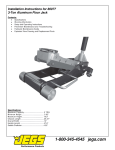
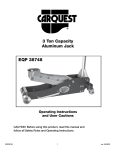
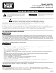
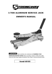
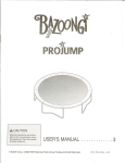
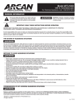
80006
2 TON CAPACITY
PROFESSIONAL SERIES ALUMINUM JACK
OWNER'S MANUAL
CONTENTS:
Page1 Specifications
2
Warning Information
3
Setup, Operating and Preventative Maintenance
4Troubleshooting
5Maintenance
6
Exploded View Drawing and Replacement Parts
SPECIFICATIONS
Capacity......................................................................................2 TON Maximum
Minimum Height.......................................................................................... 3-1/2"
Maximum Height...............................................................................................20"
Chassis Length............................................................................................28-1/2"
Chassis Width.......................................................................................................13"
Handle Length.....................................................................................................50"
Saddle Diameter........................................................................................... 4-3/4"
Net Weight.................................................................................................... 50 Lbs.
Shipping Weight......................................................................................... 54 Lbs.
80006
108/12/11
Warning Information
This is the safety alert symbol. It is used to alert you
to potential personal injury hazards. Obey all safety
messages that follow this symbol to avoid possible
injury or death.
WARNING
WARNING: Indicates a hazardous situation which,
if not avoided, could result in death
or serious injury.
IMPORTANT: READ THESE INSTRUCTIONS BEFORE OPERATING
BEFORE USING THIS DEVICE, READ THIS MANUAL COMPLETELY AND THOROUGHLY, UNDERSTAND ITS OPERATING
PROCEDURES, SAFETY WARNINGS AND MAINTENANCE REQUIREMENTS.
It is the responsibility of the owner to make sure all personnel read this manual prior to using the device. It is also the responsiblity of the device owner
to keep this manual intact and in a convenient location for all to see and read. If the manual or product labels are lost or not legible, contact JEGS for
replacements. If the operator is not fluent in English, the product and safety instructions shall be read to and discussed with the operator in the
operator's native language by the purchaser/owner or his designee, making sure that the operator comprehends its contents.
THE NATURE OF HAZARDOUS SITUATIONS
WARNING
The use of portable automotive lifting devices is subject to certain hazards that cannot be prevented by mechanical means, but only by the exercise of
intelligence, care, and common sense. It is therefore essential to have owners and personnel involved in the use and operation of the equipment who
are careful, competent, trained, and qualified in the safe operation of the equipment and its proper use. Examples of hazards are dropping, tipping
or slipping of loads caused primarily by improperly securing loads, overloading, off-centered loads, use on other than hard level surfaces, and using
equipment for a purpose for which it was not designed.
METHODS TO AVOID HAZARDOUS SITUATIONS
WARNING
•
•
•
•
•
•
•
•
•
•
•
•
•
Read, study, understand and follow all instructions before operating this device.
Inspect the jack before each use. Do not use jack if damaged, altered, modified, in poor condition, leaking hydraulic fluid, or
unstable due to loose or missing components. Make corrections before using.
Lift only on areas of the vehicle as specified by the vehicle manufacturer.
Wear eye protection that meets ANSI Z87.1 and OSHA standards.
Do not use jack beyond its rated capacity.
This is a lifting device only. Immediately after lifting, support the vehicle with jack stands capable of sustaining the load before working on the vehicle.
Use only on a hard level surface free from obstructions so the jack is free to reposition itself during lifting and lowering operations.
Center load on saddle. Be sure setup is stable before working on vehicle.
Do not move or dolly the vehicle while on the jack.
Do not use saddle adapters or saddle extenders between the stock lifting saddle and the load.
Do not use any adapters unless approved or supplied by JEGS.
Always lower the jack slowly and carefully.
Failure to heed these warnings may result in serious or fatal personal injury and/or property damage.
CONSEQUENCES OF NOT AVOIDING HAZARDOUS SITUATIONS
WARNING
Failure to read this manual completely and thoroughly, failure to understand its OPERATING INSTRUCTIONS, SAFETY WARNINGS,
MAINTENANCE INSTRUCTIONS and comply with them, and failure to comply with the METHODS TO AVOID HAZARDOUS SITUATIONS
could cause accidents resulting in serious or fatal personal injury and/or property damage.
80006
208/12/11
80006
2 TON CAPACITY
PROFESSIONAL SERIES ALUMINUM JACK
OWNER'S MANUAL
SETUP
PLEASE REFER TO THE EXPLODED VIEW DRAWING IN THIS MANUAL IN ORDER TO IDENTIFY PARTS.
1.
Depress the spring button at the bottom of the reference number (59) upper handle half and insert it in the reference number (49) lower handle half until the spring button engages the hole in the lower handle half.
2.
Remove the reference number (50) handle set screw from the reference number (53) handle yoke. Install the assembled handle into the reference number (53) handle yoke, making sure the bottom of the handle engages the release valve u-joint reference number (61).
3.
Install the reference number (50) handle set screw in the reference number (53) handle yoke and tighten the screw to secure the handle
in the yoke.
4. Air may become trapped in the hydraulic system during shipping and handling. Trapped air will affect the pumping performance of the jack. If this
occurs, follow the air purging procedure below:
a) Remove the reservoir fill plug (62).
b) With the saddle (34) in its down position, look inside the oil fill screw hole. You should be able to see the top of the power unit's
pressure cylinder. The hydraulic fluid level should be no higher than the top of the cylinder. Correct the fluid level if it is not at the
proper height with the optional fluids mentioned in the PREVENTATIVE MAINTENANCE section below.
c) Pump the jack against a load that is at least 500 lbs. (225 Kgs). After the load is raised, slightly turn the pump handle in a counter clockwise rotation so the load is very slowly lowered. While the saddle is lowering, quickly pump the handle 5 or
6 full incremental pump strokes. After pumping, lower the saddle to its full rest position.
d) Install the reservior fill plug (62). Rotate the handle in a clockwise rotation until tight and pump the lift arm to maximum height.
If the pumping condition has improved, repeat steps "a" through "d" until all of the air has been purged from the system.
OPERATING INSTRUCTIONS
This is the safety alert symbol used for the OPERATING INSTRUCTIONS section of this manual to alert you to potential personal injury hazards. Obey all instructions to avoid possible injury or death.
IMPORTANT: Before attempting to raise any vehicle, check vehicle service manual for recommended lifting surfaces.
OPERATION:
1.
2.
To raise load: Turn the handle in a clockwise direction until tight. Position the jack under the load. Proceed to pump the handle in order to raise the lift
arm to the load. As the saddle at the end of the lift arm gets closer to the load, reposition the jack so the saddle will contact the load firmly and the load
is centered on the saddle. Make sure the saddle is correctly positioned. Raise the load to the desired work height. Place jack stands of appropriate
capacity at the vehicle manufacturers's recommended support areas that provide stable support for the raised vehicle. DO NOT CRAWL UNDER VEHICLE
WHILE LIFTING VEHICLE OR PLACING OR REMOVING THE JACK STANDS! Once jack stands are positioned, turn the handle VERY SLOWLY. Lower the load
to rest on the jack stands. Inspect the relationship between the jack stands and load to make sure the setup is stable and safe. If the setup is not stable or
safe, follow the preceding steps until corrected.
To lower load: Follow the procedures mentioned in "To raise load" section of the OPERATING INSTRUCTIONS in order to raise the load off the jack
stands. Once the load has cleared the jack stands, remove the jack stands from under the load and away from the work area. Turn handle very slowly in a
counterclockwise direction until the load is completely lowered to the ground. Once the jack's lifting saddle has cleared the load, remove the jack from
under the load. CAUTION: Keep hands and feet away from the hinge mechanism of the jack.
PREVENTATIVE MAINTENANCE
1.
2.
3.
This is the safety alert symbol used for the PREVENTATIVE MAINTENANCE section of this manual to alert you to potential personal injury hazards. Obey all instructions to avoid possible injury or death.
Always store the jack in a well protected area where it will not be exposed to inclement weather, corrosive vapors, abrasive dust, or any other harmful
elements. The jack must be cleared of water, snow, sand or grit before using.
The jack must be lubricated periodically in order to prevent premature wearing of parts. A general purpose grease must be applied to all zerk grease
fittings, caster wheels, front axle, elevator arm, handle base pivot bolts, release mechanism and all other bearing surfaces. Worn parts resulting from
inadequate or no lubrication are not eligible for warranty consideration. See page 5 for lubrication instructions.
It should not be necessary to refill or top off the reservoir with hydraulic fluid unless there is an external leak. An external leak requires immediate repair
which must be performed in a dirt-free environment by an authorized service center.
IMPORTANT: In order to prevent seal damage and jack failure, never use alcohol, hydraulic brake fluid or transmission oil in the jack.
Use Chevron Hydraulic Oil AW ISO 32 or its equivalent Unocal Unax AW 150.
4.
Every jack owner is responsible for keeping the jack labels clean and readable. Use a mild soap solution to wash external surfaces of the jack but not any moving hydraulic components.
80006
308/12/11
80006
2 TON CAPACITY
PROFESSIONAL SERIES ALUMINUM JACK
OWNER'S MANUAL
5.
6.
Inspect the jack before each use. Do not use the jack if any component is cracked, broken, bent, shows sign of damage or leaks
hydraulic fluid. Do not use the jack if it has loose or missing hardware or components, or is modified in any way. Take corrective
action before using the jack again.
Any hydraulic repairs within the warranty period must be performed by an authorized service center.
INSPECTION
Visual inspection should be made before each use of the jack, checking for leaking hydraulic fluid and damaged, loose or missing parts. Each jack must be
inspected by a manufacturer’s repair facility immediately if subjected to an abnormal load or shock. Any jack which appears to be damaged in any way, is
found to be badly worn, or operates abnormally MUST BE REMOVED FROM SERVICE until necessary repairs are made by a manufacturer’s authorized repair
facility. It is recommended that an annual inspection of the jack be made by a manufacturer’s authorized repair facility and that any defective parts, decals or
warning labels be replaced with manufacturer’s specified parts. A list of authorized repair facilities is available from the manufacturer.
PROPER STORAGE
It is recommended that the jack be stored in a dry location with all wheels touching the ground on a relatively level surface.
TROUBLESHOOTING
Important: Service jacks are self-contained devices used for lifting, but not sustaining, a partial vehicular load. In accordance with ASME-PALD Load Sustaining
Test: “A load not less than the rated capacity…shall not lower more than 1/8" (3.18mm) in the first minute, nor a total of .1875" (4.76mm) in 10 minutes.”
Lowering within this range is considered normal operation and is NOT a warrantable defect.
Problem
Action
1. Unit will not lift load.
Purge air from hydraulic system by following procedure under SETUP.
2. Unit will not sustain load or feels “spongy” under load.
Purge air from hydraulic system as above.
3. Unit will not lift to full height.
Purge air from hydraulic system as above.
4. Handle tends to raise up while the unit is under load.
Pump the handle rapidly several times to push oil past ball valves in power
unit.
5. Unit still does not operate.
Contact an authorized hydraulic service center.
OWNER/USER RESPONSIBILITY
The owner and/or user must have an understanding of the manufacturer’s operating instructions and warnings before using this jack. Personnel involved in
the use and operation of equipment shall be careful, competent, trained, and qualified in the safe operation of the equipment and its proper use when servicing motor vehicles and their components. Warning information should be emphasized and understood. If the operator is not fluent in English, the manufacturer’s instructions and warning shall be read to and discussed with the operator in the operator’s native language by the purchaser/owner, making sure that
the operator comprehends its contents. Owner and/or user must study and maintain for future reference the manufacturers’ instructions. Owner and/or user is
responsible for keeping all warning labels and instruction manuals legible and intact. Replacement labels and literature are available from the manufacturer.
80006
408/12/11
80006
2 TON CAPACITY
PROFESSIONAL SERIES ALUMINUM JACK
OWNER'S MANUAL
HYDRAULIC MAINTENANCE GUIDE
IMPORTANT: Service jacks are designed for lifting purposes only; always support raised load with jack stands.
REGULAR MAINTENANCE
• MONTHLY or as necessary (depending on usage)
1.
2.
3.
4.
5.
Using a grease gun, add grease to grease fitting in the lift arm pivot shaft.
(Use a multi-purpose NLGI type grease only.)
Lubricate all linkages and pivot points.
(Use white lithium spray grease only.)
Remove handle; lubricate handle receptacle and handle end.
(Use white lithium spray grease only.)
Lubricate both rear casters, bearing and both front wheels.
(Use white lithium spray grease only.)
Tighten all accessible hardware.
#2
#3
#1
#2
#2
#4
#4
#4
#3
#2
#2
80006
#2
#2
508/12/11
80006
2 TON CAPACITY
PROFESSIONAL SERIES ALUMINUM JACK
OWNER'S
MANUAL
PARTS
LIST
AND DRAWING
Index#
1
3
Part#
Description
Qty.
Description
Rear Caster (incl. #3)
2
32
Radius Linkage Axle
1
Rear Caster Bracket
2
33
Saddle Base
1
2
RS660203
4
Qty.
Index#
Part#
RS660201
Locking Nut (M12)
4
34
Washer (M10)
2
35
5
Tooth Washer (M10)
8
36
6
Bolt (M10 x 25)
8
37
RS660234
RS6602SP
Saddle
1
Saddle Bolt
1
Rubber Saddle Pad
1
Saddle Base Axle
1
7
Washer (M14)
4
38
Rod
1
8
Spring Washer (M14)
4
39
Lift Arm Core
1
9
Bolt
4
40
Axle, Lift Arm Mounting Plate
1
41
Lift Arm Mounting Plate
1
10
Bolt (M8 x 20)
4
11
Tooth Washer (M8)
4
42
Linkage Pin
2
43
Pin (4 x 40)
1
12
Locking Nut (M18)
2
13
Washer (M8)
2
44
Linkage Block
1
14
Tooth Washer (M6)
2
45
Lift Arm Right Side Plate
1
Bolt (M6 x 20)
2
46
Rubber Guard
2
RS660216
Handle
2
47
Lift Arm Axle
1
Washer (included with #18)
2
48
RS660218
Front Wheel (includes 3, 17, 19)
2
49
RS660249
RS660250
15
16
17
18
19
Bushing (included with #18)
2
50
20
Side Plate
2
51
21
22
RS660221
Bolt (M8 x 25)
4
52
Washer (M19)
4
53
RS660253
Rod
1
Lower Handle Section
1
Handle Set Screw
1
Retaining Ring 12 (included w/#53)
1
Pump Roller (included w/#53)
1
Handle Yoke (includes #51-54)
1
23
Yoke axle
2
54
Pump Roller Axle (included w/ #53)
1
24
Lift Arm Left Side Plate
1
55
Linkage
2
25
Bolt (M10 x 16)
4
56
Bolt (M6 x 25)
2
26
Radius Linkage Axle Bolt
2
57
Lift Arm Return Spring
2
58
Power Unit Assembly
1
27
Bolt (M8 x 22)
8
28
Radius Linkage
2
29
Front Wheel Axle
1
59
RS660259
Upper Handle Section
1
60
RS6602SP
Handle Bumper
1
61
RS660261
30
Retaining Ring (16)
2
31
Link Rod Spacer
2
Seal Kit for Power Unit
62
Only index numbers identified by part number are available individually
80006
Release Assembly
1
Reservior Fill Plug
1
608/12/11