1
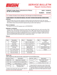
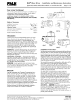
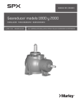
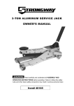
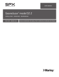
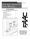
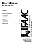
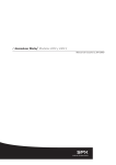
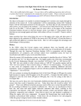
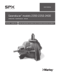
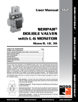
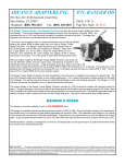
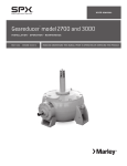
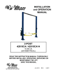
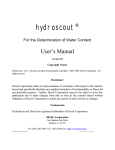
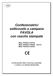
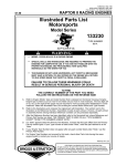
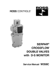
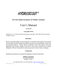
®
/ Marley Geareducer Model 34.4 and 3400 /
User Manual 01-1162B
Operation and Service Instructions
Protection Against Corrosion
Seasonal Shutdown one week to three months
As shipped, a Marley Geareducer is protected internally
against corrosion with machine enamel on unmachined parts and
with rust-proofing oil and grease on machined surfaces. These
coatings normally protect the Geareducer against atmospheric
corrosion for storage periods up to six months. However, if oil is
added to the Geareducer, it will dissolve the rust-proofing grease
and oil, requiring the Geareducer to be run once a week to keep
a protective coating of oil on all interior machined surfaces. See
“Seasonal Shutdown” section for information about nonoperating period maintenance.
At start of shutdown period, operate Geareducer until oil is
warm—120°F (50°C)—and change the oil. See section on Service
and Lubrication.
Check Geareducer exterior yearly. Touch up with paint as required.
Exposed pipe threads are coated to prevent corrosion. Touch up
coating as required.
For longer periods of shutdown, see Marley Manual 92-1308
“Downtime Instruction Manual”.
Initial Operation
The Geareducer must be filled with oil to the full oil level mark on
the Geareducer case before it is placed in operation. See Service
and Lubrication section for oil filling instructions.
Each month drain any water condensation from the lowest point
of the Geareducer and its oil system. Check the oil level and add
oil if necessary. Operate the Geareducer long enough to recoat
all the interior surfaces with oil.
To put back into operation, drain water condensation and
check oil level. Add oil if necessary.
Inspection Of Internal Parts
Remove the inspection cover plate from the side of the Geareducer case at each oil change. Check inside of Geareducer for
cleanliness of case and internal parts. If any sludge is present,
flush inside of Geareducer and connecting oil line.
Geareducers supplied with new towers include oil for the initial
filling. Oil is not furnished with Geareducers supplied as spares
or on replacement orders. Before operating the mechanical
equipment, check to be sure the oil level is at the full mark at the
Geareducer and that the external gauge placard full mark corresponds with the “Full” level in the Geareducer. Check oil lines
to be sure there are no leaks.
Service and Lubrication
Geareducer vent or vent line must be open to prevent failure of
pinion shaft oil seal—clean when necessary. Check all gasketed
joints for oil seepage. Tighten cap screws and flange bolting if
necessary.
Fill the Geareducer and oil line system with oil, using one of the
following procedures:
The Geareducer must be installed level and properly aligned
with drive shaft and motor shaft. Refer to the Driveshaft User
Manual.
1. Install oil at the opening at the Geareducer inspection cover
until it reaches the level of the “Full” mark on the Geareducer
case and at the oil level gauge. See Figures 1 and 2. Install
plug.
The horizontal part of the oil line must be level or slightly lower
at the oil level gauge than at the Geareducer. The oil capacity of
the Geareducer is 181⁄2 gallons. The oil level gauge line requires
approximately one gallon of additional oil. Refer to Table 1 on
page 5 for list of suggested lubricants.
Recommended procedure:
2. Start the fan drive and run for one minute.
3. Stop the fan drive. Allow ten minutes for oil level to stabilize
and recheck oil level at the Geareducer.
4. If necessary, repeat steps 2 and 3 until stabilized oil level is
at the proper level.
5. Check gauge placard location. “Full” mark on the placard
must be at the same elevation as the “full” mark at the Geareducer.
2
Operation and Service Instructions
Alternate procedure:
The cooling tower has an external oil gauge and drain line equipped
with a three-way valve below the oil level gauge. See Figure 1.
1. Remove pipe plug. Turn valve control stem clockwise to open
drain.
2. With Geareducer drained, the three-way valve turned clockwise, and the pipe plug removed, connect fill source (usually
a hose to a pump, to the three-way valve).
Pump oil through the hose. Check oil level occasionally by
turning the valve control stem counterclockwise and allowing
the oil level in the sight glass to stabilize.
Continue filling until full level mark is reached.
3. With the oil level at the full mark turn the valve control stem
counterclockwise to close the drain and open the valve to the
sight glass. Remove the oil filling line and reinstall pipe plug
in the three-way valve.
VENT LINE
Maintenance of the Geareducer should be scheduled as follows:
Monthly: Check oil level at least once a month using the following procedure:
Stop the fan drive. Allow ten minutes for oil level to stabilize and
check oil level at the gauge. If needed, add oil to Geareducer. If
oil is added, repeat steps 2 and 3 of recommended procedure
until stabilized oil level is at the proper height.
Semi-Annually: Change oil at least every 6 months or 3,000 hours
of operation. Refer to recommended oil change procedure.
Check the oil level placard location each time the oil is changed.
The “Full” mark on the placard must be at the same elevation
as the “Full” arrow on the side of the Geareducer case. See
Figures 1 and 2.
Oil level gauge vent must be kept open. Inspect at each oil change
and clean when necessary. Inspect internal parts and inside of
Geareducer case at each oil change—see section on inspection
of internal parts.
OIL LEVEL CHECK
OIL FILL PLUG
INSPECTION
COVER
OIL GAUGE
VENT
OIL LEVEL
GAUGE
DRAIN PLUG
OIL GAUGE
AND DRAIN LINE
THREE-WAY
VALVE
Figure 1 Service Fittings
3
Operation and Service Instructions
Repair and Overhaul
VENT
OIL LEVEL
PLACARD
NOTICE
CHECK OIL LEVEL TEN
MINUTES AFTER
FAN STOPS ROTATING
FULL
ADD
OIL
OIL LEVEL
GAUGE
FILL AT GEAREDUCER
REFER TO SERVICE MANUAL
FOR OIL CHANGE AND
MAINTENANCE RECOMMENDATIONS
SPX COOLING TECHNOLOGIES
OVERLAND PARK, KS USA
92-110A
If your Geareducer ever needs replacement or repair, SPX recommends returning the unit to a Marley factory service center.
Contact your Marley sales representative to discuss a course of
action. A factory reconditioned Geareducer carries a one year
warranty. The Marley Order Number on your cooling tower will
be required if the Geareducer is shipped back to the factory
for repair. Obtain a “Customer Return Material” tag from
the Marley sales representative in you area. To find your Marley
sales representative call 913 664 7400 or check the internet at
spxcooling.com.
Major repairs require the use of a fully equipped machine shop.
If you decide to repair or overhaul your Geareducer, refer to the
Field Repair Section and Geareducer Parts List.
Suggested Lubricants
Figure 2 Oil Level Gauge Assembly
Maintenance Service
The following list of lubricants—Table 1—is provided as reference only. These products have been recommended by their
respective manufacturers as acceptable for use in a Marley spiral
bevel and/or helical Geareducer for cooling tower applications.
This list is not an attempt to include all the lubricants that may
be satisfactory. If lubricants other than those listed are used
they must not contain any additives—such as detergents or EP
additives—which are adversely affected by moisture and could
reduce the service life of the Geareducer. Suitability of lubricants
used other than those listed rests with the customer/owner and
lubricant supplier.
Monthly
Semi-annually
Seasonal Startup or Annually
x
x
Geareducer Drive:
Inspect and tighten all fasteners including oil plug
Check for and repair oil leaks
x
x
x
Check oil level
x
R
x
Change oil
R
R
Make sure vent is open
x
x
Check driveshaft or coupling alignment
x
Inspect and tighten driveshaft or coupling fasteners
x
Check driveshaft or coupling bushing / flex elements for unusual wear
x
Lube Lines (if equipped)
Check for oil leaks in hoses and fittings
x
R
x
R – Refer to instructions within this manual
Note: It is recommended at least weekly, that the general operation and condition be observed. Pay particular attention to any changes in sound or
vibration that may signify a need for closer inspection.
4
Operation and Service Instructions
Manufacturer
Product
Amoco
American Industrial Oil 100
Marathon Ashland
Endurance R & O Oil 100
BP
Turbinol T-100
Century
Renolin RO 100
Citgo
Pacemaker 100
Exxon
Teresstic 100
Lubrication Engineers
Monolec 6404
Mobil
Mobil DTE Oil 100
Mobil
Mobil SHC629*
Penzoil
Pennzabell PB100 or RO100
Phillips 66
Magnus 100
Shell
Turbo T-100
Sun
Sunvis 9100
Texaco
Regal Oil R&O 100
Unocal (east)
Unax RX100
Unocal (west)
Turbine Oil 100
Valvoline
Valvaline R & O 100
*This synthetic product may be applicable for
high temperature service or extended oil life
Table 1
5
Parts List-3400
304
305
303
WATER SLINGER
INTERSTAGE
BEARING CAP
703
204 – 206
500
LABYRINTH RING
500
AIR VENT
202
412
603
422
20 – DOWEL PIN
GEAREDUCER
CASE COVER
302
5 – INTERSTAGE BEARING
RETAINER
FAN SHAFT
301
101 – SPIRAL BEVEL
RING GEAR
306
109
201
106
201
40
INTERSTAGE SHAFT
421
411
203
205
101 – PINION SHAFT AND GEAR
500
102
INSPECTION
COVER
105
702
PINION CAGE
401
104
PINION CAGE
CAP
602
GEAREDUCER
CASE
Figure 3 Model 3400 Exploded Assembly
6
402
103
701
601
23
Parts List-3400
1
Complete Geareducer Assembly.
100 Spiral Bevel Gear Set.
101 Set of matched spiral bevel gears including integral pinion shaft with key.
Gear ratios as follows: 2.76 to 1 2.375 to 1 2.476 to 1
102 Oil slinger.
103 Locknuts.
104 Lockwasher.
105 Pinion shaft key.
106 Interstage shaft key.
108 Thick ring gear spacer.
109 Thin ring gear spacer.
200 Helical Gear Set.
201 Set of matched helical gears including interstage shaft and special key
Gear ratios as follows: 4.182 to 1 4.70 to 1
202 Top interstage bearing retainer disc.
203 Bottom interstage bearing retainer disc.
204 Place bolts.
205 Place bolts.
206 Washers.
300
Fan Shaft Assembly.
301 Fan shaft.
302 Key.
303 Fan hub retainer.
304 Cap screw.
305 Locking plates.
306 Key.
400 Pinion Shaft Bearing Set
401 Tail, tapered roller bearing
402 Head, tapered roller bearing
410 Interstage Bearing Set
411 Lower, double row, tapered roller bearing.
Matched assembly with cone spacer
412 Upper, double row, tapered roller bearing.
Matched assembly with cup spacer
420 Fan Shaft Bearing Set
421 Lower tapered roller bearing
422 Upper tapered roller bearing
500 Shim set
501-502-503 Pinion shaft shims
504-505-506 Interstage shaft shims
507-508-509 Fan shaft shims
600
700
Gasket Set
601 Pinion cage gasket
602 Inspection cover gasket
603 Oil trough gasket
O-Rings Set.
702 Pinion cage O-ring, 93⁄4" ID" × 10" OD × 1⁄8"
703 Water slinger O-ring, 61⁄2" ID × 63⁄4" OD × 1⁄8"
701 Pinion Shaft Oil Seal
7
Parts List-34.4
304
305
303
WATER SLINGER
INTERSTAGE
BEARING CAP
307
204 – 206
500
703
LABYRINTH RING
202
AIR VENT
412
603
422
20 – DOWEL PIN
GEAREDUCER
CASE COVER
302
5 – INTERSTAGE BEARING
RETAINER
FAN SHAFT
301
108
306
101 – SPIRAL BEVEL
RING GEAR
109
201
106
201
40
INTERSTAGE SHAFT
411
203
205
101 – PINION SHAFT AND GEAR
500
102
INSPECTION
COVER
105
702
PINION CAGE
401
104
PINION CAGE
CAP
602
421
DRAIN PLUG
Figure 4 Model 34.4 Exploded Assembly
8
402
GEAREDUCER
CASE
500
704
LOWER FAN SHAFT CAP
103
701
601
23
Parts List-34.4
1
Complete Geareducer Assembly.
100 Spiral Bevel Gear Set.
101 Set of matched spiral bevel gears including integral pinion shaft with key.
Gear ratios as follows: 2.76 to 1 2.375 to 1 2.476 to 1
102 Oil slinger.
103 Locknuts.
104 Lockwasher.
105 Pinion shaft key.
106 Interstage shaft key.
108 Thick ring gear spacer.
109 Thin ring gear spacer.
200 Helical Gear Set.
201 Set of matched helical gears including interstage shaft and special key
Gear ratios as follows: 4.182 to 1 4.70 to 1
202 Top interstage bearing retainer disc.
203 Bottom interstage bearing retainer disc.
204 Place bolts.
205 Place bolts.
206 Washers.
300
Fan Shaft Assembly.
301 Fan shaft.
302 Key
303 Fan hub retainer.
304 Cap screw.
305 Locking plates.
306 Key
307 Water slinger spacer.
400 Pinion Shaft Bearing Set
401 Tail, tapered roller bearing
402 Head, tapered roller bearing
410 Interstage Bearing Set
411 Lower, double row, tapered roller bearing.
Matched assembly with cone spacer
412 Upper, double row, tapered roller bearing.
Matched assembly with cup spacer
420 Fan Shaft Bearing Set
421 Lower tapered roller bearing
422 Upper tapered roller bearing
500 Shim set
501-502-503 Pinion shaft shims
504-505-506 Interstage shaft shims
507-508-509 Fan shaft shims
600
700
Gasket Set
601 Pinion cage gasket
602 Inspection cover gasket
603 Oil trough gasket
O-Rings Set.
702 Pinion cage O-ring, 93⁄4" ID" × 10" OD × 1⁄8"
703 Water slinger O-ring, 61⁄2" ID × 63⁄4" OD × 1⁄8"
704 Lower fan shaft cap O-ring.
701 Pinion Shaft Oil Seal
9
Field Repair
General
Geareducers can be repaired in the field—however, major repairs require the use of a fully equipped machine shop. When
field repair or replacement of parts is necessary, the following
procedure is recommended for the disassembly and assembly
of the unit. If any O-ring, oil seal or gasket is to be reused, care
should be taken not to damage it during disassembly. Parts which
contain O-rings or seals should not be jerked or twisted past a
shoulder or edge. These parts are marked with an asterisk (*) in
the description below. O-rings, oil seal and gaskets should be
carefully inspected for damage before being reinstalled. SPX
recommends that new O-rings and oil seal be installed during
every major overhaul.
2
3*
4
5
5
Disassembly of Major Subassemblies
Part numbers and references—refer to Figures 3 thru 6.
1. Drain oil.
2. Remove interstage bearing cap.
3. Pull water slinger off fan shaft.*
4. Lift off Geareducer case cover.
5
5. Pull interstage shaft and fan shaft subassemblies out of
Geareducer case simultaneously.
6. Remove pinion cage subassembly.*
7. Remove lower fan shaft cap (34.4 only).
6*
Figure 5 Model 3400. Disassembly of Major Subassemblies
10
Field Repair
2
3*
4
5
5
5
6*
7
Figure 6 Model 34.4. Disassembly of Major Subassemblies
11
Field Repair
5
4
3
4
2
1
Figure 7 Disassembly of Pinion Cage
Disassembly of Pinion Cage
1
5
Part numbers and references—refer to Figures 3, 4 and 7.
1. Remove pinion cage cap. Model 3400–Remove rotating
portion of oil seal (701).
2. Remove locknuts (103) and washer (104) from pinion
shaft.
3. Press pinion shaft with head bearing cone (402) out of pinion
cage. This will free cone of tail bearing (401).
4. Remove bearing cups from pinion cage.
5. If bearing cone on head of pinion shaft is to be replaced, it
will be necessary to press off oil slinger (102) and bearing
cone at the same time.
3
4
Disassembly of Interstage
Part numbers and references—refer to Figures 3, 4 and 8.
1. Remove top and bottom interstage bearing discs (202 and
203).
2. Pull bottom bearing (411), two cones with spacer and one
cup from shaft.
2
3. Push shaft out of upper bearing (412) and retainer.
4. Remove spiral bevel ring gear and spacers from shaft.
5. Pull upper bearings from top interstage retainer (5).
1
Figure 8 Disassembly of Interstage
12
Field Repair Instructions
Disassembly of Fan Shaft
Part numbers and references—refer to Figures 3, 4 and 9.
1. Press helical ring gear (201), lower fan shaft spacer (40)
and lower cone (421) from shaft. Remove key spacer ring.
2
2. Remove upper bearing cone (422)and water slinger spacer
(703).
1
3. Remove upper fan shaft bearing cup (422) from case cover
(not illustrated).
4. Remove lower fan shaft bearing cup (421) from case (not
illustrated).
Assembly of Geareducer
Gear Match Numbers and Setting Data
Figure 9 Disassembly of Fan Shaft
Before assembling a new pinion gear in the pinion cage, check
match numbers on pinion gear and spiral bevel ring gear to be
certain they are a matched set. Gears are lapped in matched sets
at the factory and should not be separated. Numbers are etched
on both the pinion and ring gear as illustrated in Figure 10.
Pinion Cage Assembly
Part numbers and references—refer to Figures 3, 4 and 11.
1. Press oil slinger (102) onto pinion shaft.
2. Install pinion head bearing cone (402) on pinion shaft.
3. Press pinion head bearing cup (402) into pinion cage.
4. Press pinion tail bearing cup (401) into pinion cage.
MATCHED NUMBER TO BE COMPARED WITH THE SAME
NUMBER ON THE RING GEAR. (EXAMPLE CO-43)
PINION SETTING DISTANCE. (EXAMPLE 4.860)
BACKLASH (NORMAL) AT WHICH THE GEARS WERE
LAPPED. (EXAMPLE .010)
MATCHED NUMBER TO BE COMPARED WITH THE SAME
NUMBER ON THE PINION GEAR. (EXAMPLE C0-43)
THE PINION SETTING DISTANCE IS THE DISTANCE
THE END OF THE PINION SHOULD BE FROM THE
CENTERLINE OF THE RING GEAR SHAFT.
Figure 10 Gear Match Numbers and Setting Data
5. Lower pinion cage over pinion shaft until head bearing cone
(402) mates with cup.
6. Press tail bearing cone (401) onto pinion shaft.
a–Lock with lock nuts (103) and lockwasher (104) to provide bearing preload of 10 to 18 in·lbƒ (1130-2034 mN·m)
resistance to rotation of pinion shaft.
b–Crimp ears of lockwasher (104) to locknuts after obtaining
prober preload.
7.
Model 3400. Slide oil seal (701) onto pinion shaft. Model
34.4. Press oil seal (701) in pinion cage cap.
8. Assemble pinion cage cap to pinion cage with gasket (601)
or RTV. Tighten bolts (23) to 55 ft·lbƒ (75 N·m) torque.
Model 3400. Make sure rotating seal member magnetically
engages stationary element in cap.
13
Field Repair Instructions
1
2
3
5
4
6
7
8
6B
Figure 11 Pinion Cage Assembly
11
10
5
9
Interstage Assembly
Part numbers and references—refer to Figures 3, 4 and 12.
1. Install thin spiral bevel ring gear spacer (109) against top
of helical pinion. Install key (106) and spiral bevel ring gear
(101) on interstage shaft.
7
6
8
2. Press top cone of bottom interstage bearing (411) onto
interstage shaft.
3. Install double cup and spacer of bottom interstage bearing
(411).
1
4. Press bottom cone (411) into place.
5. Install retainer disc (203) with bolts. Tighten to 55 ft·lbƒ (75
N·m) torque.
6. Install thick spacer (108) on interstage shaft on top of spiral
bevel gear hub.
5
Figure 12 Interstage Assembly
14
2
7.
3
8. Lower retainer (5) over interstage shaft.
4
9. Press upper bearing cones (412) onto shaft.
Press lower cup of upper interstage bearing into
retainer (5).
10. Press upper cup (412) and spacer into retainer (5).
11. Install disc (202) with place bolts. Tighten to 150 ft·lbƒ
(204 N·m) torque.
Field Repair Instructions
4
1
2
3
3. Lower fan shaft and interstage shaft subassemblies into case
simultaneously. Engage marked spiral bevel ring gear teeth
with marked spiral bevel pinion tooth. The gear and pinion
are match-marked when lapped and must be assembled the
same way. The ring gear has the end of two teeth marked
“X” and the pinion has one tooth so marked— the gears
should be engaged with the X-marked pinion tooth between
those marked on the ring gear. Match mark location can be
checked through the inspection opening.
4. Apply a coat of Permatex® Form-a-Gasket No. 2 to surface
of Geareducer case which mates with case cover. Lower
case cover subassembly onto case, piloting both shaft
subassemblies into their respective bores.
5. Install dowel pins (20) to align bearing bores. Fasten
case cover to case with cap screws tightening to 75 ft·lbƒ
(102 N·m) torque.
Figure 13 Fan Shaft Assembly
6. Position top interstage cap shims (500) and install interstage
bearing cap with place bolts tightening to 85-90 ft·lbƒ (116122 N·m) torque.
7.
Fan Shaft Assembly
Part numbers and references—refer to Figures 3, 4 and 13.
1. Install key (306) and press helical gear (201) on fan shaft.
8. Fan shaft bearing must be preloaded to .001–.003" (.025–
.076mm) in the following manner:
a–Install labyrinth ring with sufficient quantity of shims (500)
to insure axial bearing endplay exists.
b–Mount a dial indicator to measure axial movement of fan
shaft. Support indicator stand on the cover or interstage
cap adjacent to fan shaft and position indicator to read on
machined top surface of fan shaft
c–Rotate the fan shaft slowly in one direction until all downward movement stops. Rotation is necessary to align the
bearing rollers and seat roller ends on cone lip. Record the
dial indicator reading or zero the indicator.
d–Move shaft in the opposite axial direction by attaching to
the shaft with a swivel joint and hoist or by turning Geareducer
over, allowing the weight of the shaft assembly to seat the
bearings. If a hoist is used, the lifting force should be 800 lb
(363 kg) to sufficiently overcome the weight of the fan shaft
assembly. Rotate the shaft slowly in one direction until all axial
movement stops. Record the dial indicator reading.
e–The difference in dial indicator readings (steps c and d)
is the initial fan shaft bearing end play. In order to achieve
2. Install lower bearing spacer (40) on fan shaft.
3. Press bottom bearing cone (421) onto fan shaft.
4. Press upper bearing cone (422) on fan shaft.
Model 34.4 – Install water slinger spacer (307) on top of
bearing cone.
5. Install lower fan shaft bearing cup (421) into Geareducer
case (not illustrated).
6. Install upper fan shaft bearing cup (422) into Geareducer
case cover (not illustrated).
Final Assembly–Model 3400
Part numbers and references—refer to Figures 3 and 14.
1. Install O-ring (702) onto pinion cage subassembly.
2. Bolt pinion cage subassembly to case using proper number
of shims to give indicated pinion setting distance which is
etched on front face of pinion gear. See Figure 10. Tighten
to 75 ft·lbƒ (102 N·m) torque.
Adjust shims to give proper backlash—.007–.009" normal
(.178–.228mm)—between spiral bevel gears. See Gear
Setting Procedure, page 18.
➠
15
Field Repair Instructions
8
the prescribed preload of .001" to .003" (.025–.076mm)
remove an amount of shims from between the case and
labyrinth ring equal to the measured end play plus .001"
to .003". For example if the measured end play is .005"
(.127mm), remove a total of .006 to .008" (.152–.203mm)
in shim thickness.
6
8
f–Tighten labyrinth ring cap screws to 35 ft·lbƒ (48 N·m)
torque.
g–Fill grooves of labyrinth ring and water slinger with lithiumbase grease of NLGI No. 2 consistency.
h–Install water slinger and its O-ring (703) on fan shaft.
9. Install inspection cover, gasket (602), and pipe plugs.
5
4
3
Final Assembly–Model 34.4
Part numbers and references—refer to Figures 4 and 15.
1. Install O-ring (702) onto pinion cage subassembly.
2. Bolt pinion cage subassembly to case using proper number
of shims to give indicated pinion setting distance which is
etched on front face of pinion gear. See Figure 10. Tighten
to 75 ft·lbƒ (102 N·m) torque.
3
3. Temporarily install lower fan shaft cap and secure to case
with cap screws. Leave a minimum of 1⁄8" (3mm) clearance
between cap and case. Do not install O-rings or shims at
this time.
3
4
1
4. Lower fan shaft and interstage shaft subassemblies into case
simultaneously. Engage marked spiral bevel ring gear teeth
with marked spiral bevel pinion tooth. The gear and pinion
are match-marked when lapped and must be assembled the
same way. The ring gear has the end of two teeth marked
“X” and the pinion has one tooth so marked— the gears
should be engaged with the X-marked pinion tooth between
those marked on the ring gear. Match mark location can be
checked through the inspection opening.
2
9
Figure 14 Model 3400 Final Assembly
16
Field Repair Instructions
5. Apply a coat of Permatex® Form-a-Gasket No. 2 to surface
of Geareducer case which mates with case cover. Lower
case cover subassembly onto case, piloting both shaft
subassemblies into their respective bores.
11
7
6. Install taper pins (20) to align bearing bores. Fasten case
cover to case with cap screws tightening to 45 ft·lbƒ
(61 N·m) torque.
10
6
7.
a–Position top interstage cap shims (500) and install interstage bearing cap with place bolts.
b–Adjust shims to give proper backlash—.006–.012" normal
(.152–.305mm)—between spiral bevel gears. See Gear
Setting Procedure, page 18.
c–When proper backlash has been set, tighten place bolts
to 90 ft·lbƒ (122 N·m) torque.
5
8. Fan shaft bearing must be preloaded to .001–.003" (.025–
.076mm) in the following manner:
4
a–Initially install a quantity of shims between case and bottom cap to insure that axial bearing end play exists.
b–Mount a dial indicator to measure axial movement of fan
shaft. Support indicator stand on the cover or interstage
cap adjacent to fan shaft and position indicator to read on
machined top surface of fan shaft.
c–Rotate the fan shaft slowly in one direction until all downward movement stops. Rotation is necessary to align the
bearing rollers and seat roller ends on cone lip. Record the
dial indicator reading or zero the indicator.
d–Move shaft in the opposite axial direction by attaching to
the shaft with a swivel joint and hoist or by turning Geareducer
over allowing the weight of the shaft assembly to seat the
bearings. If a hoist is used, the lifting force should be 700 lb
(317 kg) to sufficiently overcome the weight of the fan shaft
assembly. Rotate the shaft slowly in one direction until all axial
movement stops. Record the dial indicator reading.
4
4
12
5
➠
9
1
8
2
3
Figure 15 Model 34.4 Final Assembly
17
Field Repair Instructions
e–The difference in dial indicator readings (steps c and d) is
the initial fan shaft bearing end play. In order to achieve the
prescribed preload of .001 to .002" (.025–.051mm) remove
an amount of shims from between the case and bottom cap
equal to the measured end play plus .000 to .002". For example if the measured end play is .005" (.127mm), remove
a total of .005 to .007" (.127–.177mm) in shim thickness.
Caution–If Geareducer is in the upright position when bottom
cap is removed, block under the ring gear to prevent gear
from dropping down onto lower interstage bearing retainer
(roller cage).
9. Install O-ring in bottom cap and install bottom cap. Tighten
cap screws to 80 ft·lbƒ (109 N·m) torque.
10. a–Coat labyrinth recess in case cover with Permatex No. 2
and install labyrinth ring.
b–Fill grooves of labyrinth ring and water slinger with lithiumbase grease of NLGI No. 2 consistency.
11. Install water slinger and its O-ring (703) on fan shaft.
12. Install inspection cover, gasket (602), and drain plug.
Gear Setting Procedure
Part numbers and references—refer to Figures 3, 4 and 16.
The proper mounting of the gear set is essential to obtain long
life and smooth operation of the gears. The pinion cage position
adjustment is obtained by shims under the flange of the pinion
cage. Shims are placed under the top interstage bearing cap to
adjust ring gear position. The gear setting may require several
attempts before obtaining the proper backlash and tooth contact
pattern.
The gear and pinion are match-marked when lapped and must be
assembled the same way. The ring gear has the end of two teeth
marked "X" and the pinion has one tooth so marked—the gears
should be engaged with the X-marked pinion tooth between those
marked on the ring gear. Match marks can be checked through
the inspection opening.
With the marked teeth of the gear engaged, check backlash
with dial indicator—see Figure 16. The indicator can be installed
through the inspection cover opening. Change shims under top
interstage bearing cap until backlash is between .007–.009"(.178–
.228mm) normal to ring gear tooth.
With gears adjusted for proper backlash, blue (Prussian Blue in
oil) the gear teeth. Drive the pinion by turning ring gear in both
directions for several revolutions. Observe the contact pattern
on both gears on both sides of the teeth. The contact pattern
should be as shown in Figure 17.
If correct tooth contact pattern is not obtained on first attempt,
refer to Figure 17—these illustrations show the two cases of
“out-of- position contact” in the extreme. One of the remedies
indicated will correct the out-of-position contact—compare the
tooth contact pattern with the illustrations in Figure 17 and
choose the required remedy.
POINT OF NORMAL
BACKLASH MEASUREMENT
Figure 16 Gear Backlash Measurement
18
When proper tooth contact has been obtained, recheck the backlash at marked teeth. If it is within the desired range—.007–.009"
(.178–.228mm), check backlash with dial indicator at two additional points 120° apart (with inspection cover removed), and
as shown in Figure 16. All backlash readings must be within the
specified range. If backlash is not within the limits, adjust ring gear
height with shims until it is, checking again as described.
CORRECT PINION AND RING GEAR TOOTH CONTACT PATTERNS
*
INCORRECT RING GEAR TOOTH CONTACT PATTERNS
OUT OF POSITION CONTACT
*
ORIGINAL
PATTERN
AFTER
BREAK IN
CAUSE:
PINION TOO CLOSE TO
GEAR CENTER.
REMEDY: MOVE PINION OUT.
CONCAVE SIDE
CONVEX SIDE
*
RING GEAR
CONVEX SIDE
CONCAVE SIDE
ENTERING
LEAVING
DIRECTION OF ROTATION
OUT OF POSITION CONTACT
CAUSE:
PINION TOO FAR FROM
GEAR CENTER.
REMEDY: MOVE PINION IN.
*
Figure 17 Spiral Bevel Gear Tooth Pattern
The tooth contact pattern should again be checked to determine
if adjusting the backlash has produced any shift. If it has shifted,
move the pinion in the opposite direction the gear was moved
with respect to the cone center. If the gear mounting distance
is reduced, increase pinion setting distance, and vice versa, an
amount proportional to the number of teeth in the respective
members. For example: on a 10 to 1 gear set, if the ring gear
was moved .010" (.25mm) , the pinion should be moved 0.001"
(.025mm). This would be necessary only if the contact pattern
had visually shifted due to movement of the ring gear while
adjusting backlash.
Installation and Lubrication
Refer to the Operation and Service Instructions at the beginning
of this manual.
When setting a used set of gears, follow the method outlined
above. However, depending upon the amount of wear, it may be
necessary to set the gears up with slightly greater backlash in
order to obtain proper contact. Proper tooth contact pattern
is the most important factor for correct installation.
Should a condition be encountered where correct contact cannot
be obtained as described in this manual, the Geareducer should be
returned to Marley in exchange for a factory reconditioned unit.
19
7401 WEST 129 STREET | OVERLAND PARK, KANSAS 66213 UNITED STATES | 913 664 7400 | [email protected] | spxcooling.com
In the interest of technological progress, all products are subject to design and/or material change without notice.
©2009 SPX Cooling Technologies, Inc. | Printed in USA
Manual 01-1162B