1
Super SKY
AUG.2000 5130-26135-87
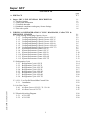
CONTENTS
A . PREFACE
page
P-1
1 . Super SKY LINE GENERAL DESCRIPTION
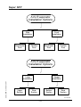
1.1 Product Options
1.2 Name plate information
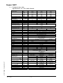
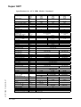
1.3 Technical data table
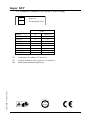
1.4 Standards compliance and agency license listings
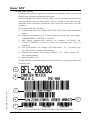
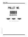
1.5 Bar-code system
1-1
1-1
1-2
1-3
1-5
1-6
2 . WIRING & REFRIGERATION CYCLE DIAGRAMS, CAPACITY &
PRESSURE CHARTS
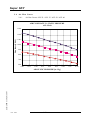
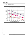
2.1 Using cooling and heating Capacity Curves
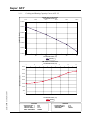
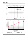
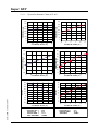
2.1.1 Cooling and Heating Capacity Curves AVL 25
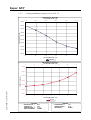
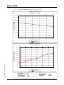
2.1.2 Cooling and Heating Capacity Curves AVL 35
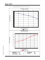
2.1.3 Cooling and Heating Capacity Curves AVL 50
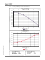
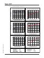
2.1.4 Cooling and Heating Capacity Curves AVL 60
2.1.5 Cooling and Heating Capacity Curves AVL 603
2.1.6 Cooling and Heating Capacity Curves AVL 753
2.1.7 System Performance Charts AVL 25
2.1.8 System Performance Charts AVL 35
2.1.9 System Performance Charts AVL 50
2.1.10 System Performance Charts AVL 60
2.1.11 System Performance Charts AVL 603
2.1.12 System Performance Charts AVL 753
2-1
2-1
2-2
2-3
2-4
2-5
2-6
2-7
2-8
2-9
2-10
2-11
2-12
2-13
2.2 Refrigeration Cycle
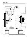
2.2.1 Refrigeration Cycle AVL 25
2.2.2 Refrigeration Cycle AVL 35
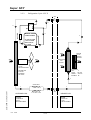
2.2.3 Refrigeration Cycle AVL 353
2.2.4 Refrigeration Cycle AVL 50
2.2.5 Refrigeration Cycle AVL 503
2.2.6 Refrigeration Cycle AVL 60
2.2.7 Refrigeration Cycle AVL 603
2.2.8 Refrigeration Cycle AVL 753
2-14
2-14
2-15
2-16
2-17
2-18
2-19
2-20
2-21
2.3 AVL – Low Profile Ducted Mini Central Unit
2.3.1 Installation
2-22
2-22
2.4 Air flow Curves
2.4.1 Air flow Curves AVL 25 / 35 / 50 / 60
2.4.2 Air flow Curves AVL 753
2-26
2-26
2-27
2.5 Electrical & wiring Diagram
2.5.1 AVL 1 PH
2.5.2 AVL 3 PH
2-28
2-28
2-29
1--1 I