1
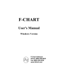
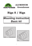
SWINGING WINDOWS SASH AND FRAME--CLAD CASEMASTER
REGLAZING, CLAD CASEMASTER WINDOWS
Clad Casemaster Windows
Reglazing Instructions
5/15/2003
19970220
11/2004
4.2.12
Marvin Service Manual
11708609
SWINGING WINDOWS SASH AND FRAME--CLAD CASEMASTER
REGLAZING, CLAD CASEMASTER WINDOWS - 3/31/03 AND LATER
BEFORE YOU BEGIN
S Read these instructions thoroughly BEFORE beginning to
reglaze your Marvin window.
S Alterations to Marvin products including window films,
insulating or reflective interior window treatments or
additional glazings can cause excessive heat buildup
and/or condensation. This may lead to premature failures
not covered under warranty by Marvin Windows and
Doors.
S Prior to beginning, inspect new glass for: size and type,
cracks, scratches, collapse, water spots, dirt or other
imperfections.
S Replacement parts listed within these instructions may be
obtained by contacting your Marvin representative.
WARNING: Practice safety! Wear safety glasses or
goggles and appropriate protective equipment,
including gloves, when reglazing your Casemaster Clad
windows.
ATTENTION: Specifications and technical data are subject
to change without notice. For the most current version of this
instruction, visit our website at www.marvin.com.
IMPORTANT: The following instructions detail the removal of
sash and reglazing of clad Casemaster sash produced on
3/31/03 or later. For sash produced before this date, see
instructions,
“In
Sash
Clad
Windows--Reglazing
Instructions”, reference part number 19970639.
NOTE: Numbers listed in parentheses ( ) are metric
equivalents in millimeters rounded to the nearest whole
number.
STANDARD PARTS NEEDED
Operator
sash
Replacement glass
YOU WILL NEED TO SUPPLY
Safety glasses
Protective gloves
Small pry bar
Caulking gun
Flexible putty knife
Rubber mallet
#2 Phillips screwdriver
Isopropyl alcohol
Scrap wood blocks
Hammer
Plastic tipped hammer
Stiff putty knife
Flat bladed screwdriver
Grade NS Class 25 sealant per ASTM C920
INDEX
Long
extension
arm
Operator
track
1
2.
Page
Removing Sash . . . . . . . . . . . . . . . . . . . . . . . . . . . . .
Removing Old Glass . . . . . . . . . . . . . . . . . . . . . . . . .
Installing New Glass . . . . . . . . . . . . . . . . . . . . . . . . .
Replacing Sash . . . . . . . . . . . . . . . . . . . . . . . . . . . . .
4.2.13
4.2.14
4.2.15
4.2.16
Units with Dyad (single arm) Roto Gear: Crank open
the sash. Using a screwdriver snap back the butterfly clip
which locks the dyad operator extension arm to the
operator bracket pivot pin. (Similar to that shown in
illustration 2.)
Screwdriver
Butterfly
clip
Short
extension
arm
Pivot
pin
CAUTION: Replacement glass can be very heavy. It may
be necessary to obtain the assistance of another
individual when attempting to remove or replace glass
and/or sash. Always use proper eye and hand protection
when handling glass.
Short
extension
arm
Removing Sash
NOTE: Sash with daylight openings of less than 14 1/2″ (368)
will use hinged single arm operator gear. Skip to step 3 for
these units.
1.
Units with Dual Arm Roto Gear: Crank open the sash
until the nylon roller on the long extension arm of the roto
gear lines up with the arrow on the operator track. (The
operator track is located on the bottom of the operating
sash). Disconnect the long extension arm from the
operator track by pushing the roller down through the
opening which is in line with the arrow.
See illustration 1.
11/2004
Butterfly
clip
Pivot
pin
2
3.
4.2.13
Units with Dyad (single arm) Roto Gear: Crank open
the sash. Using a screwdriver snap back the butterfly clip
which locks the dyad operator extension arm to the
operator bracket pivot pin. (Similar to that shown in
illustration 2.)
Marvin Service Manual
11708609
SWINGING WINDOWS SASH AND FRAME--CLAD CASEMASTER
REGLAZING, CLAD CASEMASTER WINDOWS - 3/31/03 AND LATER
4.
With the sash open 90 degrees remove the bottom hinge
arm from the hinge track pivot pin. Some models have a
snap ring on the pin, these arms can be disconnected by
prying off with a screwdriver. See illustration 3. Repeat
for the top hinge. The sash is now free to swing so care
must be taken to prevent damage to the sash and avoid
personal injury.
7.
Partially remove the sash weatherstrip from all four
corners of the sash on the stile side to expose the screws.
Using a Phillips screwdriver, back the screws out
approximately 1/4″ (6). DO NOT COMPLETELY
REMOVE THE SCREWS. See illustration 6.
Stile
weatherstrip
Pivot
pin
Back the
screws out
appr. 1/4″
Hinge
arm
6
3
5.
Remove the sash by sliding hinge pivot shoes toward the
pivot pins until they disengage from the hinge track.
Carefully remove sash from unit frame See illustration 4.
Hinge pivot
shoe
Hinge
track
8.
Carefully turn the sash over and cut the interior glazing
between the glass and wood in the same manner as the
exterior.
9.
Place 4 blocks of wood between the table and the exterior
glass pane. Blocks should be high enough to elevate the
entire sash off the work surface. Starting at a corner on
the stile, place another small wood block on the back side
of the cladding near the sash weatherstrip and begin
pounding the cladding from the wood. Be sure to start
over both stile and rail cladding. Tap firmly but be careful
not to bend corner key. Once the corner comes loose,
continue around the perimeter of the sash every
6--8″ (152--203). The cladding will drop onto the table
once completely released from the wood. Set aluminum
assembly aside. See illustration 7.
Sash
Sill
4
Sash interior side up
Removing Old Glass
6.
Place the sash on a flat sturdy surface, exterior side up.
Cut the exterior sealant glazing by pushing a flexible
putty knife between the glass and the aluminum
cladding. Work the knife around the entire perimeter.
See illustration 5.
Back of
cladding
Flexible
putty knife
Pounding block
Pounding
block
5
7
11/2004
4.2.14
Glass
support
blocks
Work surface
Marvin Service Manual
11708609
SWINGING WINDOWS SASH AND FRAME--CLAD CASEMASTER
REGLAZING, CLAD CASEMASTER WINDOWS - 3/31/03 AND LATER
Carefully press down on the glass near the wood
assembly to release. Discard old glass and save the
rubber glazing blocks for use later.
11.
Remove all the old sealant from the glazing rabbet on
both wood and aluminum surfaces. Use a flat headed
screwdriver or other tool to completely remove all sealant
from the aluminum glazing rabbet. See illustration 8.
Remove any remaining sealant residue from all glazing
surfaces with isopropyl alcohol.
Carefully place the
new glass into the
wood
assembly.
Insert rubber glazing
blocks
removed
earlier at quarter
points around the
glass: two on the
bottom, two on one
side, one on the top
and one on the
opposite side. See
illustration 10.
Center
Quarter
points
10.
13.
Center
CAUTION:
Before performing the next step, avoid
personal injury and be sure that you are wearing protective
gloves and safety glasses.
Quarter
points
Remove old
sealant from wood
glazing rabbet and
from aluminum
glazing rabbet
10
8
Quarter
points
Quarter
points
14.
Tighten the screws on the cladding assembly. Inspect
the corners to ensure proper alignment of the miter joint.
It may be necessary to back screws out and retighten or
replace the corner keys. If the latter is the case, contact
your Marvin representative for details and ordering of
parts.
15.
Inspect vinyl connectors on cladding assembly and
replace if damaged. Make sure all are seated properly.
16.
Apply a 3/16″ continuous bead of sealant in glazing
rabbet of cladding assembly. See illustration 11.
Installing New Glass
12.
Apply a 1/4″ continuous bead of sealant to the wood
glazing rabbet. See illustration 9.
Wood
sash
Sealant
bead
Cladding
Assembly Sealant
bead
Glazing
rabbet
Glass
rabbet
Glass
rabbet
Glass
rabbet
Sealant bead
Sealant bead
9
11
11/2004
4.2.15
Marvin Service Manual
11708609
SWINGING WINDOWS SASH AND FRAME--CLAD CASEMASTER
REGLAZING, CLAD CASEMASTER WINDOWS - 3/31/03 AND LATER
17.
Carefully lay the cladding assembly on top of glass and
wood sash assembly. Align the cladding assembly so
that the vinyl connector barb lines up with the kerf in the
wood assembly. See illustration 12.
21.
Attach the top hinge arm to the track stud. Tap with a
plastic headed hammer to secure the arm over the snap
ring or use a flat screwdriver to return the butterfly clips
to the locked position (depending on hardware type).
Repeat this procedure for the bottom hinge. See
illustration 14.
Cladding
Sealant
bead
Wood
sash
Vinyl
connector barb
Kerf
Glass
Hinge
arm
Pivot
pin
12
18.
19.
Push down forcefully on the corners of the cladding
assembly. Use a large rubber mallet to tap the cladding
down until fully seated into the wood assembly.
Do not clean excess sealant from glass until fully cured
(at least 24 hours).
14
22.
Replacing Sash
CAUTION: It may be necessary to obtain the assistance of
another individual before attempting the following steps.
Do not let go of sash until all sash hardware is properly
attached to the frame.
20.
Snap the short extension arm onto the sash bracket
stud. Use a flat bladed screwdriver to return the
butterfly clip to the locked position. See illustration 15
(dual arm roto gear shown). On units with single arm
roto--gear, crank the sash shut.
Screwdriver
Butterfly
clip
Short
extension
arm
Pivot
pin
Place the sash in the frame opening at 90 degrees,
positioning the sash hinge shoes on the hinge tracks
close to the sash track studs. Engage the shoes with the
track flange and slide into the installed position (away
from the studs). See illustration 13.
Short
extension
arm
Hinge pivot
shoes
Sash
Butterfly
clip
Pivot
pin
15
Hinge
track
Installation Tip: To seat butterfly clips or hinge
arms push on the clip or arm until you feel or hear it
click into place. To check to see if the clip or arm is
properly attached gently pull up on the arm, if it
detaches, reattach the arm and reseat.
Sill
WARNING! Check all hardware, clips and
retainers to ensure all parts are secure and
properly seated. Failure to properly install
the sash may result in the sash disengaging
from the frame, causing potential damage to the sash
and/or personal injury.
13
11/2004
4.2.16
Marvin Service Manual
11708609
SWINGING WINDOWS SASH AND FRAME
23.
On units with dual arm Roto gear, crank open the
extension arm until the nylon roller is positioned under
the arrow on the sash track.
24.
Center the roller under the opening and pull up into the
track. Turn the crank to engage the roller fully into the
track and check for proper sash operation. See
illustration 16.
Operator
sash
Long
extension
arm
Operator
track
16
11/2004
4.2.17
Marvin Service Manual
11708609