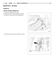
1
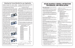
CARBURETOR
P/N 0-80450 & 0-80451
INSTALLATION, TUNING, AND
ADJUSTMENT MANUAL
199R-9881
NOTE: These instructions must be read and fully understood before
beginning installation. If this manual is not fully understood,
installation should not be attempted. Failure to follow these
instructions, including the pictures may result in subsequent
system failure.
INTRODUCTION:
CONGRATULATIONS on your purchase of a Holley carburetor! We feel that you have purchased the finest performance
carburetor manufactured today. Should you need information or parts assistance, please contact our Technical Service
Department at 1-270-781-9741, Monday through Friday, 7 a.m. to 5 p.m. CST. Please have the part number of the product you
purchased on hand when you call.
This carburetor has been calibrated and designed as a multi-purpose carburetor for General Motors passenger cars and trucks
only. Holley Performance Products cannot and will not be responsible for the results of a misapplication. Primary design
attention has been given to low-end and mid-range torque characteristics as well as good fuel economy and the ease of
installation.
NOTE: Not legal for street use in California on vehicles originally equipped with 2-barrel carburetors for which there was no 4barrel option.
WARNING! This carburetor is NOT designed for use with ANY automatic overdrive transmission. If used on an
automatic overdrive vehicle, SEVERE transmission damage WILL result.
This carburetor is only calibrated or certified for specific, cataloged applications and must be used on “square” flange intake
manifolds.
Carburetor adapters are not recommended to adapt to “spread-bore” intake manifolds, since adapters may have an adverse
effect on cylinder-to-cylinder distribution, and ultimately, total engine performance.
MAINTENANCE WARNING! Fuel system components, including fuel lines and the carburetor, should be inspected
periodically to make sure that no fuel is leaking and that all hoses are sound. Today’s
controlled-emissions engines create higher temperatures in the engine compartment.
These high temperatures promote faster aging of non-metallic materials.
Hoses that exhibit surface cracks when bent to a 180° position should be replaced. The presence of liquid fuel requires regular
maintenance and inspection of lines and hoses, re-tightening of hose fittings, and the re-torquing of fuel system flange nuts
(where applicable). Tighten the Holley carburetor fuel bowl screws to 25-30 in./lbs. of torque in a clockwise direction.
Periodically, recheck the torque of the fuel bowl screws at regular maintenance intervals.
REMOVAL:
1.
Identify, label, and disconnect the vacuum lines to the air cleaner. Labeling these connections will help ensure that they will
be properly re-assembled to the air cleaner after the installation of your Holley carburetor.
WARNING: Carefully protect the open end of the fuel lines, so that no foreign particles can enter. Wrap the end of the fuel line
with a clean lint-free cloth.
2.
Carefully disconnect the fuel line.
3.
Disconnect and label all vacuum lines to the carburetor, noting those lines that run from the distributor, spark delay valve,
temperature sensing valve, EGR valve, fuel vapor canister, and so forth. Use Diagram 1 or 2, whichever applies to your
original carburetor.
2
CARBURETOR HOSE CONNECTIONS*
Carburetor Feature
Fuel Inlet
Ported EGR Signal
Full Vacuum Spark Signal
Timed Spark Signal
Canister Purge
PCV
Carburetor Bowl Vent
Full Vacuum Sources
Choke Hoses
Port / Hose Number
1
2
3a
3b
4
5
6
7a, 7b
8 and 9
*The diagrams of original equipment carburetors
represent a consolidation of many applications into a
single view. Your particular carburetor may not have
all of the features shown.
Table 1
4.
Disconnect the PCV hose and power brake hose.
5.
Disconnect the choke rod, if used.
6.
Disconnect and remove the throttle linkage and automatic transmission kickdown linkage. SAVE ALL RETAINING CLIPS.
7.
Unbolt and remove the carburetor.
NOTE: If the intake manifold is to be changed at this time, install the new manifold according to the manifold manufacturer’s
directions. Holley cannot accept responsibility for the validity of the instructions for non-Holley manifolds. You may want
to consider the following suggestions if you are changing the manifold:
A.
Run a clean-up tab into each manifold bolt hole in the cylinder heads. This will remove any foreign deposits and
enable even torquing of the manifold bolts. Chances of manifold vacuum leaks resulting from manifold warpage will
be minimized by this extra attention.
B.
Holley strongly recommends an original equipment (or equivalent) intake manifold gasket for your year and size
engine. Using a gasket for a different engine model year or certain non-equivalent gaskets can lead to valley-side
manifold vacuum leaks. Coat each side of the intake gaskets with a good silicone-based sealant.
C.
Make sure that when installing the aluminum intake manifold, all gaskets are exactly in place and all bolts are
evenly and securely tightened. This will minimize the chance of having a manifold vacuum leak and having to,
possibly re-install the manifold. (See the Rough Idle and Vacuum Leaks Section.)
3
INSTALLATION:
1.
A few GM applications with air conditioning use an idle step-up solenoid to increase idle speed during compressor
operation. If possible, remove the solenoid and its retaining nut. If the solenoid is permanently fixed to the original
carburetor, you may want to purchase GM parts 1997416 solenoid and 7042654 nut and install them on your new Holley
carburetor, using the appropriate bracket.
2.
Take the short ground lead from the unassembled parts and connect the bayonet end to the proper terminal on the Holley
electric choke cap. See Figure 1.
CAUTION! The polarity of the choke cap terminals must be observed to avoid damaging the heating element.
3.
Fasten the other end of the ground wire to a suitable location, such as under the head of one of the screws retaining the
secondary throttle diaphragm.
4.
Install the carburetor-mounting studs (provided) in the proper location on the intake manifold.
5.
Place the gasket(s) on the manifold flange.
Figure 1
NOTE: When using a dual plane intake manifold, use the thick gasket; if “X” configuration single plane manifold is installed, use
one thin gasket.
NOTE: Some dual plane manifolds may require extra carburetor clearance for safe operation. In these instances, two thick
gaskets are supplied and should be installed with the carburetor.
6.
4
Remove the throttle cable ball and automatic transmission kickdown stud (if any) from the original carburetor. Mount these
in similar locations on the Holley throttle lever. If the original throttle ball is too large, a new throttle ball is provided in the
unassembled parts package. On Pontiac Firebird installations equipped with the 400 engine and automatic transmission, it
may be necessary to install the long kickdown stud, nut, and lock washer supplied in the package. Tighten both nuts to 36
in./lbs. of torque. See Figure 2.
Figure 2
7.
Figure 3
Place the carburetor on top of the intake manifold, making sure to engage the transmission kickdown stud. Hand install the
hold-down nuts first and then progressively snug down in a criss-cross pattern with a proper wrench. See Figure 4.
WARNING! Overtightening may result in a warped or cracked carburetor throttle body. The carburetor should be
tightened down sufficiently to prevent vacuum leaks, but not so tight as to cause damage.
Figure 4
8.
9.
Figure 5
Reconnect the throttle cable and return spring. On those models using a transmission kickdown cable, it may be necessary
to adjust the cable to get wide-open throttle. Do this as follows:
A.
Disengage the locking mechanism on the kickdown cable sheath.
B.
Move the throttle lever to the wide-open position, allowing the cable sheath to slip past the locking mechanism.
C.
Re-engage the cable locking mechanism.
Have someone operate the accelerator pedal to ensure correct travel to open and return to idle, without sticking. On some
installations that are originally equipped with a two-barrel carburetor, it might be necessary to obtain a four-barrel throttle
cable mounting bracket to provide proper linkage operation. On installations having a kickdown actuating switch on the
passenger’s side of the firewall, adjust according to the manufacturer’s service manual.
5
10. Reconnect the vacuum hoses to the appropriate fittings, according to Diagram 1. For example, connect the hose marked
“2” on the Rochester 2GC and Rochester Quadro-Jet to the port marked “2” on the Holley 4160, using the EGR line adapter
supplied in the unassembled parts, if necessary.
A.
For proper EGR valve operation, it is necessary to connect the ported EGR signal marked #2. On Rochester QuadraJet (Diagram 1), to the port marked on the Holley 4160 (Diagram 3).
B.
On Rochester 2GC applications, the PCV connection is into the manifold, therefore it does not appear in Diagram 1.
You must connect the PCV to port 5 on the Holley 4160.
C.
On applications using a carburetor bowl vent, connect the vent hose to fitting 6 on the Holley 4160. Otherwise, the
fitting must be capped, using the plug provided.
D.
The full manifold vacuum sources 7a and 7b provide vacuum for operation of the air cleaner, transmission, and
accessories. Use the plastic “T” provided to supply vacuum where needed. Additional “T”s may be purchased at most
automotive supply stores.
E.
Choke hoses 8 and 9 on Rochester carburetors are not used with the Holley 4160.
F.
Cap all fittings and vents not connected with the plugs provided.
11. Connect the PCV hose to the fitting at the rear of the throttle body. If the existing hose is too short, a PCV hose connector
and additional PCV hose are provided.
12. Any requirements for fresh air may be satisfied by “T”-ing into the choke fresh air hose using a plastic “T” available at most
automotive parts stores.
13. Reconnect the idle step-up solenoid wire, if used.
WARNING! In all cases, it is essential that no foreign particles enter the fuel line during installation.
14. Carefully remove the protecting cloth from the end of the fuel line to the carburetor. Use provided clamps, if needed.
15. If installation requires cutting metal fuel lines, cut the fuel line with a good tube cutter. This will minimize the change of
producing metal chip particles. If a hacksaw must be used, then metal chips must be removed.
WARNING! In all cases where the fuel line has been cut, it is essential that it be clean to ensure that no metal particles
enter the fuel bowl after the new carburetor installation. This is performed by disconnecting the fuel line at
the pump and blowing the line clean with compressed air. Holley DOES NOT recommend the procedure
where the coil wire is disconnected, the engine cranked for a few revolutions, and the fuel is collected in a
container. This procedure is unsafe, because sparking can occur either at the coil or at the distributor end
of the coil wire. This could then ignite any fuel spilled in the engine compartment.
16. As an added precaution, we recommend that an inline fuel filter be installed just ahead of the carburetor inlet fitting.
CAUTION! The use of a quality inline fuel filter, such as Holley P/N 162-524 or equivalent, is mandatory to provide
additional protection against possible flooding problems that could result from unfiltered foreign particles
becoming lodged between the fuel inlet and the needle and seat. Filter elements should be blown clean
with compressed air every 6,000 miles and replaced every 12,000 miles.
17. Attach the bayonet end of the long electrical lead to the remaining “positive” terminal of the choke cap. The other end must
be connected to an ignition-activated 12 volt source.
WARNING! Connecting the choke cap to the ignition or ignition coil could result in unacceptable choke operation, poor
fuel economy, and possible engine misfiring, since the voltage delivered to the spark plugs will be severely
reduced by the drain imposed by the choke cap. Suitable ignition activated 12-volt sources are most
electrical relays, as well as the leads to accessories, such as windshield wipers. DO NOT connect this wire
to the original equipment (O.E.) electric choke source. This may not be a 12V source.
18. Start the engine and check all lines to/from the carburetor for vacuum leaks. Check the fuel lines and fittings for leaks.
19. With the engine at operating temperature, set the idle speed to the manufacturer’s specifications by adjusting the idle speed
screw (Fig. 3). Consult the emission control sticker ro the manufacturer’s service manual for the correct procedure for
setting idle speed.
20. Install the air cleaner stud from the unassembled parts package. Slowly lower the hood to ensure that the stud will not
contact the hood when closed. Do not slam the hood the first time.
6
21. Place the gasket on the sealing flange and install the appropriate air cleaner, connect any vacuum lines to the fitting on the
air cleaner. It may be necessary to use an air cleaner adapter, like Holley P/N 17-14 to provide adequate clearance
between the carburetor and the air cleaner.
WARNING! Inadequate clearance between the throttle lever and the air control could result in uncontrolled speed.
GENERAL INFORMATION:
Idle Mixture Adjustment:
The idle mixture of your new Holley carburetor has been pre-set at the factory to give the best idle while meeting emission
requirements. It should not be necessary to adjust the idle mixture screws beyond the stops of the plastic limiter caps.
This carburetor is equipped with a “reverse” idle system. Screwing the idle adjustment needles IN, “RICHENS” the mixture.
Backing the screws OUT, “LEANS” the mixture. This system has two peculiar characteristics:
A.
It is frequently impossible to “kill” an engine by leaning the mixture. Likewise, it is often difficult to make an engine “lope”
by richening the mixture.
B.
It is possible to adjust the idle mixture within the range of the limiter caps. The mixture needles affect the delivered fuel
mixture up to approximately 45 mph. Fuel economy for low speed can be improved in most, but not all cases, by a
leaner adjustment of the needle. Trial and error is the best approach.
CAUTION! Adjusting the mixture screws beyond the rich stop of the limiter cap will cause the engine to emit illegal
amounts of air polluntants. Adjusting them beyond the lean stops may result in engine damage due to lean
misfire.
If the limiter caps are removed for any reason, the idle mixture is best set with an exhaust gas analyzer, available in most dealer
garages and many independent garages. The analyzer should read .2-.6% CO using the following steps:
A.
With the engine at operating temperature, set the idle speed to the manufacturer’s specifications.
B.
Connect the exhaust gas analyzer. For vehicles equipped with a catalytic converter, the analyzer probe must be
upstream of the catalyst.
C.
Turn both idle mixture screws clockwise (rich) until they lightly seat (See Fig. 1). Reset the idle to correct speed.
D.
Equally turn both screws counter-clockwise (lean) in 1/4 turn increments. Reset the idle to correct speed.
E.
Note the exhaust gas analyzer reading. Repeat Step D until the reading is .2-.6% CO.
Air Cleaner:
The choke has been designed for use with a snorkel-type air cleaner, which provides pre-heated air to the carburetor. This air
cleaner configuration is essential for proper choke operation, especially in severely cold climates. If an open element is used, it
may be necessary to adjust the electric choke cap two notches lean (See Fig. 1) to ensure complete choke come-off in cold
weather. Pre-heated air also improves fuel vaporization and combustion, which will ultimately improve fuel economy and
driveability.
Fast Idle Adjustment:
The fast idle speed during choke operation may need adjustment to meet the vehicle manufacturer’s specifications. To re-set
fast idle, hold the throttle wide opn, with the engine “OFF”, to expose the fast idle adjusting screw below the choke cap. (See
Fig. 5). Using a 1/4” open-end wrench, turn the screw clockwise to increase idle speed. Turn it counter-clockwise to decrease
idle speed.
NOTE: Make sure that you have not turned the fast idle adjustment screw so far clockwise that the throttle will not return to curb
idle with the choke off. Also, the screw must contact the second highest step of the plastic fast idle cam during warmup.
Rough Idle & Vacuum Leaks:
If rough idle exists after the engine has been fully warmed-up, check for vacuum leaks. Vacuum leaks can result from
unplugged vacuum fittings, a torn or improperly installed flange gasket, improper torque on the throttle body-to-manifold nuts, or
improper re-connection of vacuum lines.
7
If the intake manifold was changed, a manifold vacuum leak can occur at the cylinder head/intake manifold mating surfaces.
This may be due to a damaged gasket, improper gaskets, or improper torquing of manifold bolts. Manifold vacuum leaks may
also occur from the valley side of the manifold. These leaks are very difficult to detect, unless a discernible whistle can be
heard.
If the vacuum leakage cannot be remedied by tightening the manifold bolts and the carburetor flange nuts, the manifold must be
re-installed to prevent engine damage due to lean misfire.
GENERAL:
In addition to your Holley replacement carburetor, attention must be directed to correct spark plug gap and heat reange, sound
primary and secondary wiring, correct valve lifter adjustment, and to operational PCV, EGR, and heat riser systems. These
separate but important factors, each affect the economy and performance of your engine.
An automotive system cannot perform to its maximum potential without proper maintenance and adjustment of all its
components.
Holley Technical Support
P.O. Box 10360
Bowling Green, KY 421012-7360
Phone: 1-270-781-9741
Fax: 1-270-781-9772
For online help, please refer to the Tech Service section of our website: www.holley.com
199R-9881
Date: 11-20-02
8