1
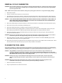
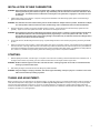
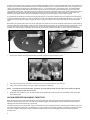
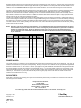
COMPETITION CARBURETORS MODEL 4150 HP PRO-SERIES Installation and Adjustment Instructions CONGRATULATIONS on your purchase of Holley carburetor! We feel that you have purchased the finest performance carburetor manufactured today. Should you need information or parts assistance, please contact our Technical Service Department at 1-270-781-9741, Monday through Friday, 7 a.m. to 5 p.m. CST. Please have the part number of the product you purchased on hand when you call. WARNING! These instructions must be read and fully understood before beginning installation. Failure to follow these instructions may result in poor performance, vehicle damage, personal injury, or death. If these instructions are not fully understood, installation should not be attempted. APPLICATIONS: P/N 0-80507-1 0-80540-1 0-80575 0-80541-1 0-80528-1 0-80529-1 0-80535-1 0-80576 0-80509-1 0-80511-1 0-80496-1 0-80498-1 0-80577 0-80513-1 0-80514-1 USE Race, NASCAR Approved Race Race, Supercharger Race Race Race Race Race, Supercharger Race, NASCAR Approved Race, NASCAR Approved Race Race Race, Supercharger Race Race Calibration Touring Series Style Racing Gasoline Gasoline Gasoline Gasoline Gasoline Alcohol Gasoline Winston Cup Style Racing Winston Cup Style Racing Gasoline Alcohol Gasoline Gasoline Gasoline CFM 390 600 600 650 750 750 750 750 830 830 950 950 950 1000 1000 SECONDARIES Mechanical Mechanical Mechanical Mechanical Mechanical Vacuum Mechanical Mechanical Mechanical Mechanical Mechanical Mechanical Mechanical Mechanical Mechanical BOOSTER TYPE Conventional Conventional Conventional Conventional Double -step Down Leg Double -step Down Leg Double -step Down Leg Double -step Down Leg Double -step Down Leg Annular Double -step Down Leg Double -step Down Leg Double -step Down Leg Double -step Down Leg Annular SPECIAL NOTE: Part number 0-80507-1 is shipped from Holley without the high-speed air bleeds to allow for the Touring Series Style racing calibration. See the air bleed section for clarification and identification of the high-speed air bleeds. NOTE: These carburetors are not legal for use in California on any pollution-controlled motor vehicle. INTRODUCTION: Holley Performance Products has written this instruction sheet for the installation of the Model 4150 HP PRO-SERIES carburetors. This instruction sheet contains all the information needed to install these carburetors. Please read all the WARNINGS and NOTES, as they contain valuable information that can save you time and money. Holley Performance Products cannot and will not be responsible for any alleged or actual engine or other damage, or other conditions resulting from misapplication of the carburetor described herein. However, it is our intent to provide the best possible products for our customer; products that perform properly and satisfy your expectations. Should you need information or parts assistance, please contact our Technical Service Department at 1-270-781-9741, Monday through Friday, 7 a.m. to 5 p.m. Central Time; please have the part number of the product you purchased when you call. GENERAL INFORMATION: • • • • • • • • This instruction sheet cannot contain all of the information, which may be desired by some individuals. Further clarification is available in HOLLEY CARBURETORS, published by H.P. books and available at your Holley distributor (P/N 36-73). An in-line fuel filter should be installed between the fuel pump and the carburetor. Recommended fuel pressure should be set at 7-1/2 psi maximum, 5 psi minimum. Fuel pressures above 7-1/2 psi can create severe fuel control problems and are not recommended. Fuel lines should be a minimum of 3/8”. A Non-restrictive open-element air cleaner kit is recommended (Holley P/N 120-102). The pump cam adjustment kit is available under Holley P/N 20-12. Slosh tubes for preventing fuel starvation during rapid acceleration are available under Holley P/N 122-5000. Vacuum secondary diaphragm springs (if applicable), which vary secondary opening, are available under Holley P/N 20-13. For additional parts and accessories, see the Holley Performance Parts Catalog. REMOVAL OF OLD CARBURETOR: WARNING! Prior to and after installing your new carburetor, manually operate the throttle lever, checking for any sticking or binding. Failure to do so may result in a runaway engine or a wide open throttle condition, which could result in engine damage personal injury and/or death. NOTE: Make a visual inspection of the carburetor, looking for any missing parts, bent levers, or any possible shipping damage. 1. Remove the air cleaner. 2. Label any connections to the carburetor, such as the fuel line. 3. After labeling all connections to the carburetor, carefully disconnect all hoses and lines. When removing the fuel line, slide a rubber cap plug over the end to prevent fuel from running out, which may create a fire hazard. Use a clean metal container to collect any spilled fuel. DANGER! DO NOT SMOKE WHEN WORKING AROUND GASOLINE OR GASOLINE VAPORS. EXTINGUISH ALL OPEN FLAMES. AN OPEN FLAME, SPARK, AND/OR EXTREME HEAT COULD RESULT IN A FIRE AND/OR EXPLOSION CAUSING SERIOUS INJURY, DEATH, AND/OR PROPERTY DAMAGE. 4. Remove the throttle linkage and automatic transmission controls from the throttle lever. Disassemble and save the throttle return spring. 5. Remove the two front and two rear-attaching manifold flange nuts. 6. Remove the throttle cable bracket, if so equipped, (located at the right rear attaching bolt). 7. Remove the carburetor by lifting it straight upward. Sometimes the carburetor can stick to the manifold gasket, requiring it to be pried loose. Before prying, double check to make sure all the carburetor attaching bolts and connections have been removed. 8. Place clean shop towels or rags into the manifold opening to prevent dirt or debris from entering the engine. Keep exposed ends of vacuum and fuel lines free from dirt. WARNING! Failure to cover the intake opening with a clean towel could result in dirt or debris entering the engine. Dirt or debris in the induction system can cause engine damage, which may necessitate a complete engine overhaul. 9. Remove the gasket from the intake. Remove any gasket material that may have adhered to the manifold. DO NOT gouge the intake manifold sealing surface during removal of old gasket material. 10. Remove the shop towels from the intake and vacuum out the intake channel to ensure no dirt or debris is left in the intake system. Place a clean shop towel over the entire intake opening until you are ready to install the new carburetor. FLUSHING THE FUEL LINES: During fuel line installation, be careful to avoid introducing any dirt particles which could enter the fuel inlet and jam open the needle and seat resulting in carburetor flooding, malfunctioning and/or possible engine fire. In all cases where the fuel line has been cut, it is essential that it be cleaned to prevent contamination from entering your new carburetor. The fuel line must be flushed of rust, dirt and other debris. DANGER! Holley DOES NOT recommend the procedure where the coil wire is disconnected, the engine cranked for a few revolutions, and the fuel is collected in a container. This procedure is unsafe because sparking can occur either at the coil, or at the distributor end of coil wire, which may ignite any fuel spilled in the engine compartment. This could cause an EXPLOSION or FIRE, which may result in serious injury or death! WARNING! Flush fuel lines only in a well-ventilated area and away from all sources of heat or flame. Failure to follow these instructions may cause gasoline vapors to ignite resulting in a fire or explosion, which may result in serious injury or death. WARNING! Wear eye protection when performing this step. Failure to wear eye protection can result in gasoline or other contaminates entering the eye, which could result in permanent eye damage or blindness. 1. Disconnect the fuel line at the fuel pump. 2. Using a compressed air source, blow the fuel line clean. 2 INSTALLATION OF NEW CARBURETOR: WARNING! Holley Performance Products highly recommends that a quality fuel filter be installed with any replacement carburetor to catch any dirt that may still remain in the system. Any dirt that may enter the carburetor can cause the carburetor to flood or malfunction. A carburetor that has a malfunction caused by dirt in the system due to negligence of the owner will void the warranty. 1. Install a flange gasket on the manifold. If a spacer is being used the installation order will be flange gasket, spacer and another flange gasket over the manifold stud bolts. WARNING! The carburetor should be installed directly onto its manifold without an adapter whenever possible. Sometimes an adapter can create problems with hood clearance, airflow, throttle linkage, fuel line attachment and/or fuel mixture distribution. 2. Place the carburetor in position over the four stud bolts and secure in place. To avoid warping the carburetor flange, tighten each bolt gradually. Tighten in a criss cross pattern to 60 in./lbs. Be careful not to overtighten the nuts. WARNING! Over tightening the carburetor manifold flange hold-down-nuts may result in a warped or cracked carburetor throttle body. The carburetor hold down nuts should be tightened down progressively in a criss-cross pattern to 60 in./lbs., so that vacuum leaks are prevented and to avoid causing damage to the throttle body. A carburetor that has been damaged due to negligence of the owner will void the warranty. 3. Connect the fuel lines, throttle linkage and return springs. Operate linkage to assure correct travel by fully opening and closing the throttle by hand. 4. Attach all vacuum lines, where necessary. Not all model 4150’s have vacuum connections, however, some model 4150s are equipped with three vacuum tubes. The larger tube at the base of the carburetor provides full manifold vacuum at idle. Use this for PCV, power brake etc. The smaller tube attached to the metering block is timed spark (vacuum provided anytime after off idle). The distributor is usually attached here. Plastic “T’s” (available through the Holley Performance Catalog) may be used to complete the installation. STARTING: 1. Without operating the throttle, crank the engine. It may take 15 to 30 seconds of cranking to allow the fuel bowls of the carburetor to fill. If the engine does not start, stop cranking, open and close the throttle twice and crank again until the engine starts. WARNING! DO NOT crank the engine for more than 15 seconds at a time. Cranking longer than 15 seconds can overheat the starter, resulting in premature starter failure. 2. After starting the engine check fuel lines and inlet fittings for possible fuel leaks. WARNING! If any fuel leakage or weeping is detected, shut off the engine immediately, and wipe up any fuel. Locate the source of the leak and correct before proceeding any further. TUNING AND ADJUSTMENT: Before you begin to tune your carburetor for your particular vehicle, you must get a “feel” for your vehicle’s performance so that any changes you make (Good or Bad) will be readily apparent. Be patient and make only one change at a time so that only that change can be fully analyzed. This cannot be overemphasized, as there are no “short-cuts” to peak performance. Recording each change and the resulting performance increase or decrease will provide you with a “Handbook” of how vehicle performance is affected by individual carburetor adjustments. This may be helpful in the future or on other applications. 3 FUEL LEVEL (FLOAT LEVEL): The float(s) controls the fuel delivery, however if the float(s) are not properly adjusted a fuel starvation or a flooding affect could result. This operation is difficult to do accurately on a rough-idling vehicle. Figure 1 Figure 2 Figure 3 1. For a mechanical fuel pump, remove coil wire and crank engine over for 10 seconds to allow fuel bowls to fill. This procedure can prevent a power valve blow out. Reconnect coil wire when finished. For electric fuel pumps, let the fuel bowls fill in stages by turning the ignition on and then off, let fuel pump run for a few seconds at a time. This procedure can prevent the needle from being forced up at an angle not allowing the needle to seat properly. 2. Remove the sight plug from the fuel bowl. 3. Start the vehicle. 4. Loosen the lock screw at the top of the assembly. 5. Turn the adjusting nut while holding the screw in place until the fuel level is at the bottom of the sight plug hole. A slight trickle should be seen at the threads. Turn the adjusting nut clockwise to lower the fuel level and counter-clockwise to raise the fuel level. 6. Tighten the lock screw while holding the adjustment nut. 7. Replace the sight plug and lightly tighten with a screwdriver. 8. Flush the fuel bowl by revving the engine a few times with the transmission in neutral. 9. Remove the sight plug to confirm your setting. A slight trickle should be seen at the threads. Adjust, if necessary. Replace the sight plug and tighten. IDLE SPEED SCREW: The idle speed screw in most cases is the only screw you should adjust. The Idle screw controls the throttle plate position at idle, which in turn raises or lowers the engine rpm by allowing more or less air/fuel mixture into the engine. It does not control the air/fuel mixture. Here are the proper steps for setting the engines idle speed. 1. Find the proper idle rpm on the underhood decal of your vehicle. If this decal is not available, find a service manual that references your vehicle and engine and find the recommended idle rpm. 2. Start the engine and allow it to warm up. 3. Connect a tachometer, if your vehicle is not so equipped. 4 4. Make sure the parking brake is on and the wheels are blocked. Place the automatic transmission in drive, the manual transmission in neutral or as stated on the underhood decal. 5. If the idle speed is slower than recommended, turn the screw clockwise to speed up the rpm. If the idle speed is too fast, turn the idle screw clockwise to slow down. This adjustment should be made to both the primary and secondary screws in equal amounts, so that the throttle plates are opened the same amount. NOTE: There is a Holley secondary idle adjustment lever, P/N 26-137, that allows the secondary throttle plate to be adjusted without carburetor removal. Figure 4 Figure 5 IDLE MIXTURE NEEDLES: Idle mixture needles control the air/fuel mixture at idle. The amount of air/fuel mixture used at idle is controlled by engine vacuum. So, when tuning the idle mixture, you are actually tuning for the best manifold vacuum. Idle mixture needles are found on the metering blocks. Your carburetor will have four idle mixture needles; one for each venturi. This is known as four-corner idle. If you change one idle mixture needle, you are required to change the other idle mixture needles the same amount. Here are the proper steps for setting the idle mixture needles. 1. Attach the vacuum gauge to the manifold vacuum port usually at the rear of the carburetor and on the throttle body. 2. Adjust each idle mixture screw the same amount to achieve the highest possible vacuum reading without increasing the idle speed screw. 3. Now that the idle mixture is set, it may be necessary to go back and reset the idle speed using the idle speed screw. Continue back and forth between the tuning of the idle mixture needles and idle speed screws until little change is noticed in manifold vacuum and idle speed is correct. Figure 6 ACCELERATOR PUMP: The accelerator pump’s purpose is to make up for the lag in fuel delivery to enable the engine speed to increase in response to throttle opening. Differences in vehicle weight, transmissions, and rear axle ratios affect the amount of fuel and the delivery rate that should be provided by the accelerator pump. This may necessitate the customizing of your accelerator pump to your vehicle and its use. NOTE: The old saying, “if a little is good, a lot is better”, does not apply to the proper tuning of the accelerator pump. Your car’s performance can be just as bad if it receives “too much fuel too soon” as if it receives “too little fuel too late.” Two factors that affect the accelerator pump’s delivery are the pump cam and the pump shooter (discharge nozzle). The pump cam determines the total volume of fuel and affects delivery rate; the pump shooter affects delivery rate and helps determine the duration of the shot. 5 In general, the #1 locations on the pump cams provide a moderate initial delivery and have a greater final delivered volume. The #2 locations on the pump cams provide a greater initial delivery and have a lesser total delivered volume. The pump shooters have a number stamped on their casting, which designates the shooter size in thousandths of an inch, i.e., a #25 shooter has a .025” discharge orifice. The smaller diameter nozzles lengthen the pump shot duration and are used with heavier vehicles or with vehicles equipped with lower numerical rear axle ratios. Larger diameter nozzles (.035 - .037) shorten the pump shot duration, but deliver a greater initial volume of fuel. These sizes should be used on applications where engine speed will increase rapidly (vehicles with good power-to-weight ratios). Best acceleration is achieved when the accelerator pump delivers the lean, best-power, air/fuel ratio to the engine; not when the maximum volume of fuel is supplied. An important point should be kept in mind when tuning a Double Pumper, the secondary accelerator pump must supply fuel for a sufficient time so that the secondary main nozzles can “start up” and deliver fuel to the engine after the secondary throttle plates are opened. If the nozzles do not start by the time the pump shot expires, bogging will result. To apply the information above, follow these steps for tuning the accelerator pump. Best starts or racing starts usually result when the rear tires break loose for the first 10 to 25 feet, this allows engine speed to increase rapidly to get the secondary main nozzles started. If wide tires, which provide extremely good traction, do not permit the rear tires to break loose, bogging can result. Best times may be recorded with narrower tires. Tire size may have as significant an affect on vacuum operated secondary carburetors since the secondary throttle plates will not open until the secondary nozzles are exposed to enough vacuum to get them started. Figure 7 1. Figure 8 Change pump shooters until the smallest diameter nozzle that provides the crispest response is found. Figure 9 2. Then change the pump cams and locations until the right cam is found that provides even more response. 3. Finally, change the pump shooter once again, until the crisp response is maximized. NOTE: 4. If a nozzle size is desired that seems “in between” the nozzle sizes provided, then the nozzle can be drilled to the desired size by using a wire drill held in a pin vise. At this point, there should be no bogs, flat spots or black smoke (indicating excessive richness) when accelerating at wide open throttle from a standing start. VACUUM OPERATED SECONDARY THROTTLES: Many people have the misconception that opening the secondary throttle plates sooner will provide increased performance and quicker drag strip times. Others think they must “feel” a kick when the secondaries engage. Still others believe that they should disconnect the vacuum diaphragm and make the secondaries open mechanically. Let’s discuss these points in a reverse order. First, if we could make our vacuum operated secondary carburetors perform better by opening the secondaries mechanically, it would be to our advantage to do so since all that vacuum actuating hardware is expensive and requires much time and money to calibrate. Mechanical secondary carburetors all utilize a pump shot to prevent bogging when the secondaries are opened. Secondly, those 6 who “feel” a kick when the secondaries engage are actually feeling a flat spot during initial acceleration because the secondaries have already begun to open and have weakened the fuel delivery signal to the primary boosters. The engine is struggling to increase speed and what they actually feel are the secondary nozzles “crashing in” as the engine finally reaches the speed where it provides the proper fuel delivery signal to primary and secondary venturi. Third, opening the secondaries early causes the situation described above. The secondaries must not open until the engine requires the additional air. This allows torque to increase along the peak torque curve. Performance is compromised less by holding the secondaries closed a little longer than by opening them a little too soon. If the opening rate of the vacuum operated secondaries is properly calibrated there should not be a “kick”, only a smooth increase in power should be felt. In general, heavier cars require stiffer secondary diaphragm springs than light cars. Air cleaner configuration and restriction plays an important part in spring selection also, so make sure to use your air cleaner when evaluating your vehicles performance after each change. DO NOT expect to “wing” the throttle and see the secondary begin to open. If they do they will probably open too soon. Secondaries should open only when the engine is under a load. DO NOT clip a spring in an effort to make a spring lighter so that the secondaries will open sooner. Strange as it may seem, clipping springs actually increases spring rate and will delay opening. So in order to tune the secondaries follow the steps below. The secondary springs are available from your local Holley retailer. 1. All vacuum secondary 4150 HP Pro-Series carburetors come with quick change vacuum secondaries. Remove the two screws holding the spring over to the vacuum secondary housing. 2. Remove the secondary spring cover. The spring will be attached to the cover. Avoid damaging the diaphragm under this cover. 3. Remove and change the spring. The stiffer the spring, the later the secondaries will open. The lighter the spring, the earlier the secondaries will open. 4. Reassemble in reverse order. Avoid damaging the diaphragm between the secondary housing and the secondary spring cover. JETTING (MAIN JETS): Due to varied applications that a universal performance carburetor will work with, no additional tuning jets have been included. However, a few tips on jetting are provided to help you understand their purpose. Holley’s Quick Change Fuel Bowls are recommended if repeated changes or experimentation with the main jets will be performed. • • • • • • Out of the box jetting is extremely close for most applications. In most cases it will be unnecessary to increase jet size more than four numbers greater than out of the box jetting. However, exceptions could arise when the carburetor is mounted on a very large volume, plenum-ram manifold. Carburetors are calibrated at 70° at sea level. Decrease the jet size one number (approx. .002) for approximately every 2000 ft. increase in altitude. Increase jet size one number for every 35° drop in temperature. Holley jets are broached, flowed and stamped according to flow rate. Never drill jets, this seriously alters flow characteristics. Stamped numbers are reference flow numbers and DO NOT indicate drill size. Spark plugs provide the best indication of proper jetting. Allow plugs to cool before jumping to conclusions. Alcohol jets: Holley alcohol jets are required with the following HP carburetors: 0-80498-1 950 CFM and 0-80535-1 750 CFM. These carburetors are built with unique metering blocks designed to accept the physically larger size of the alcohol main jet. Two lengths are available: a "standard length" jet and a "extended" length jet. The standard length jet can be used with a stock unmodified float; the extended length jet is like a jet with a built-in slosh tube, and must be used with a special "notched" float, for clearance. Holley has such a notched float available under P/N 116-11. Use the root jet part number "122-" followed by the suffix "Jet Number". The following sizes are available: Basic Part No. 122Standard Extended Drill Standard Extended Drill Standard Extended Length Jet No. Length Jet No. Size Length Jet No. Length Jet No. Size Length Jet No. Length Jet No. 132 1132 .132 150 1150 .150 172 1172 136 1136 .136 152 1152 .152 176 1176 138 1138 .138 154 1154 .154 180 1180 140 1140 .140 156 1156 .156 184 1184 142 1142 .142 158 1158 .158 188 1188 144 1144 .144 160 1160 .160 192 1192 146 1146 .146 164 1164 .164 196 1196 148 1148 .148 168 1168 .168 200 1200 Drill Size .172 .176 .180 .184 .188 .192 .196 .200 NOTE: A special Alcohol Jet Kit, P/N 36-201 is also available. This kit consists of 4 of each of the 24 alcohol jet sizes that range from .132" to .200". These jets will not fit the standard Holley metering block. AIR BLEEDS: WARNING! Adjustment of the air bleeds is not recommended. A competent mechanic with a complete and thorough knowledge of carburetors, fuel systems, and engine requirements should only perform air bleed adjustments. Failure to follow these recommendations may result in a lean fuel/air mixture causing severe engine damage, property damage, serious injury, and/or death. WARNING! Air bleed sizes should not be adjusted more than six (6) sizes in any one direction from the original air bleeds as shipped from Holley. Air bleed adjustment beyond six (6) sizes could result in a lean fuel/air mixture causing severe engine damage, property damage, serious injury, and/or death. 7 Experimenting with air bleeds is not recommended and should only be attempted by an expert carb tuner. Countless hours of testing have been performed on expensive flow stands to obtain the proper bleed size for a given calibration. It is unlikely that a better air bleed calibration can be obtained, however the 4150 HP Pro-Series are equipped with removable air bleeds. Here is some basic knowledge of how air bleeds work. The main or high-speed air bleeds affect the entire range of the main-metering system. The purpose of the main metering system and main air bleeds is to emulsify the fuel before entering the discharge nozzle to be discharged into the air stream in the venturi. The fuel/air mixture becomes leaner as air bleed size is increased. Decreasing the size of the main air bleeds will decrease pressure across the main jet, which in turn will pull more fuel through the main system creating a richer fuel/air mixture. The main or high speed air bleeds also act as an anti-siphon or siphon breaker so fuel does not continue to discharge or dribble into the venturi after airflow is reduced or stopped. At high speeds the fuel/air mixture must be on the rich side to prevent damage to the engine. The idle system supplies fuel at idle and low speeds. The idle system requires a richer mixture than at cruise speed. Unless the idle mixture is richer a slow and irregular combustion will occur known as a rough idle. Decreasing the idle air bleed size richens the idle mixture by increasing the pressure drop in the system. Increasing idle air bleed size leans the idle mixture by reducing the pressure drop across the idle air bleeds. The same conditions can be created by backing out the idle mixture screws, which will increase the pressure across the idle air bleeds, pushing more fuel from the idle well creating a richer fuel/air ratio. The Idle mixture screw is the only adjustment recommended for controlling the idle fuel/air mixture richness or leanness. NOTE: See Figure 10 for air bleed locations and identification. It is recommended that all jet sizes be documented before any tuning of the air bleeds or main jets is started. Below is a chart for recording the jet and air bleed sizes for your 4150 HP Pro-Series carburetor as shipped from Holley. Should you adjust the air bleed size or main jet size, this chart will allow the tuner to return the carburetor to the original jetting. Please place this information in a safe place along with any other documentation for your carburetor. P/N PRIMARY JETTING Main Idle High Speed SECONDARY JETTING Main Idle High Speed 0-80507-1 0-80540-1 0-80575 0-80541-1 0-80528-1 0-80529-1 0-80535-1 0-80576 0-80509-1 0-80511-1 0-80496-1 0-80498-1 0-80577 0-80513-1 0-80514-1 Figure 10 POWER VALVES: The number stamped on a power valve, such as 65, indicates the manifold vacuum below which the power valve is operational. In this case, all manifold vacuums below 6.5” Hg., the power valve is operating. Generally, a 65 power valve is sufficient for most high performance applications that have a manifold vacuum of 12” Hg or higher. However, some problems can result with radically cammed, full-race machines equipped with automatic transmissions. These vehicles often “idle” at 2000 rpm, approx. 6.0” Hg. At this point the main nozzles are starting to feed and richen the mixture (supplied by the power valve) and the engine will probably “load up”. To correct this problem, install a 45 or 35 power valve. If the engine has a manifold vacuum of 12” Hg or less, a good way to determine power valve size is take the manifold vacuum at idle and divide that number by two. The answer is the power valve size. This will provide idling and proper fuel flow under wide open throttle conditions when manifold vacuums seldom rise above 1” Hg. SLOSH TUBES: Slosh tubes can be used in the secondary jets to prevent the secondary main jets from being uncovered as fuel rushes to the back of the fuel bowl during extreme accelerations. Holley Performance Products P.O. Box 10360 Bowling Green, KY 42102-7360 Technical Service: 1-270-781-9741 Fax: 1-270-781-9772 For online help, please refer to the Technical Information section of our website: www.holley.com Copyright 2002 Holley Printed in U.S.A. Performance Products, Inc. 199R-10016-2 Date: 10-15-02 8