1
Cardio Vascular Profiling System
VP-1000/2000
Non-invasive Vascular Screening Device
BP-203RPE II
Pulse Wave Unit
TU-100
Operation
Manual
Important:
To operate this device properly and safely, please read this operation
manual carefully before using it. Also, this manual should be located in a
convenient place for future reference.
P.No.1730486B
08/2006
00_top
Page 1
06.8.24, 0:22 PM
Adobe PageMaker 6.5J/PPC
Caution
00_top
Principles
• No part of this manual should be reprinted or reproduce without permission from
Omron Healthcare Co.
• Omron Healthcare Co. maintains right to modify the contents without prior notice.
• Ample care has been taken in writing this manual; please contact Omron Healthcare
Co. if you have any questions about the content of this manual.
• If there are missing or disarranged pages, the manual will be exchanged.
Inquire at the place of purchase.
Trade Mark
• Product names mentioned in this manual may be a trademark or a registered trademark of other companies.
Page 2
06.9.16, 5:30 PM
Adobe PageMaker 6.5J/PPC
Table of Contents
Before Use .......................................................................................................................... 2
Symbols and Safety Terms ......................................................................................................................................... 3
Outline ................................................................................................................................ 10
Explanation of Technical Terms .................................................................................................................................
Measurement Principle of NIBP .................................................................................................................................
Outline of TU-100 (only for VP-2000) ......................................................................................................................
Identification ...............................................................................................................................................................
Meaning of the Symbols .............................................................................................................................................
Jog Dial and Function Switch ....................................................................................................................................
11
14
16
21
24
25
Initial Screen ................................................................................................................................................ 26
Installation ................................................................................................................................................................... 27
Power On Procedure ................................................................................................................................................... 28
Check before Use ........................................................................................................................................................ 29
Measurement Procedure ..................................................................................................... 31
Application of the BRACHIAL CUFF ......................................................................................................................
Application of the ANKLE CUFF .............................................................................................................................
Application of ECG ELECTRODES CLIP ................................................................................................................
Application of PCG SENSOR ....................................................................................................................................
32
35
38
40
Measurement Information Input .................................................................................................................. 42
ID Number Input .........................................................................................................................................................
Patient Information Input ............................................................................................................................................
Entering Measurement Conditions .............................................................................................................................
Start of Measurement ..................................................................................................................................................
Results .........................................................................................................................................................................
Printing ........................................................................................................................................................................
43
44
45
50
53
54
Exercise Measurement ................................................................................................................................. 57
Exercise Measurement Procedure ............................................................................................................................... 57
Screen Display During Measurement ......................................................................................................................... 61
Measurement Procedures VP-2000 (with tonometric sensor) .................................................................................. 64
Settings ............................................................................................................................... 77
Menu Screen ................................................................................................................................................ 78
Procedure ..................................................................................................................................................................... 78
Menu Contents ............................................................................................................................................................ 78
User Setting .................................................................................................................................................. 79
Functions That Can Be Set ......................................................................................................................................... 80
Reprint ..........................................................................................................................................................
Time/Date Setting ........................................................................................................................................
Usage Frequency Report ..............................................................................................................................
System Information ......................................................................................................................................
83
84
85
86
Maintenance........................................................................................................................ 87
Troubleshooting ........................................................................................................................................... 88
Cannot Print Correctly ................................................................................................................................................
Error Messages ............................................................................................................................................................
About Maintenance .....................................................................................................................................................
Disposal .......................................................................................................................................................................
Maintenance of the Device .........................................................................................................................................
Cleaning of Sensors/Attachments ...............................................................................................................................
Cuff Replacement .......................................................................................................................................................
Technical Specification of BP-203RPEII ...................................................................................................................
Technical Specifications of TU-100 ...........................................................................................................................
88
88
96
97
98
99
100
101
103
–1–
00_top
Page 3
06.8.24, 0:22 PM
Adobe PageMaker 6.5J/PPC
Before Use
Omron Healthcare Co. would like to thank you for purchasing this unit.
This device provides indices of PWV (pulse wave velocity), ABI (ankle-brachial index), pulse waveforms, mecanocardiogram and PCG to support early
detection and diagnosis of arteriosclerosis.
The device you have purchased is comprised of the following components.
VP-2000
BP-203RPE II (Non-invasive Vascular Screening Device)
TU-100
(Pulse Wave Unit)
ST-200A (Trolley)
VP-1000
BP-203RPE II
ST-100A (Trolley)
The VP-2000 includes a TU-100 (pulse wave unit) , check that the carotid
arterial tonometric sensor and the femoral arterial tonometric sensor are
included as components.
Please be sure to familiarize yourself with usage, warnings, capacity, and limitations in order to apply this device safely. After reading, please locate this
manual in a convenient place for everyone who uses this device.
– 2 – Before Use
01_before
Page 2
06.8.23, 1:51 PM
Adobe PageMaker 6.5J/PPC
Important
In order to use this device correctly and safely, please read this manual carefully.
This manual should be located in a convenient place for future reference.
Indications for ensuring safety
In this manual and the device, there are indicating symbols that are designed to prevent hazards from body and properties and to promote collect and safe use. Those indications and
meanings are explained as follows. Please familiarize yourself with these symbols before
reading the manual.
DANGER indicates an eminently hazardous situation which, if not
avoided, will result in death or serious injury.
WARNING indicates a potentially hazardous situation that, if not
avoided, may result in death or serious injury.
CAUTION indicates a potentially hazardous situation that, if not
avoided, may result in minor or moderate injury.
Indicates the existence of contents which are included within or
nearby the symbol. (In this case the symbol warns us of the possibility of
electrical shock.)
Indicates a prohibited behavior. Specific instructions are included
within or nearby the symbol. (In this case, prohibiting disassembly.)
Indicates necessary action or instructional information. Specific instructions are included within or nearby the symbol. (In this case, pulling
the power cord by its connector.)
Other symbols
It indicates information that should be known when operating this
CAUTION!
device.
Before Use
01_before
Page 3
06.8.23, 1:51 PM
Adobe PageMaker 6.5J/PPC
–3–
DANGER
Do not use this device in the presence of a flammable anesthetic mixture
with ignitable gas or oxygen or nitrous oxide. It will cause an explosion.
WARNING
Only doctors or authorized personnel should attempt to operate this unit.
Please do not allow patients to operate this unit in order to avoid accident.
This unit is designed to conduct examinations.
This unit is not intended for monitoring patients in the ICU, OR and ER.
This unit cannot be used in the following places:
Rooms that cause electrical noise such as MRI room, CT, X-ray room, operational room with the electrosurgical unit, rooms with microwaves, etc.
Also, avoid using other medical equipment while using this unit.
During the examinations, operator should sit with the unit and by the patient, and pay attention to the status constantly.
This unit can be damaged by the electric energy from a defibrillator. During defibrillation, remove the sensors from a patient.
Do not operate a cellular and/or radio trans-receiver in the presence of
this unit in order to avoid malfunction.
Use only authorized accessories and options in order to avoid accident.
Please be familiar with manuals accompanied with accessories and options. There is no warning about accessories and options.
Do not disassemble or reconstruct medical electron instrument in order
to avoid fire and electrification.
Operate the equipment at the voltage described on the rating label to
avoid fire and electrocution.
In case of using this device for patients with infection, device itself, cuffs and sensors are necessary to be cleaned and sterilized before using for other patients.
To operate this unit safely and properly, please inspect this unit before
use.
– 4 – Before Use
01_before
Page 4
06.8.24, 0:23 PM
Adobe PageMaker 6.5J/PPC
WARNING
Do not put anything on top of this unit in order to avoid fire and electrocution.
Do not place heavy materials on the AC power cord in order to avoid fire
and electrocution.
During maintenance, turn OFF and unplug the AC cord in order to avoid
electrocution.
If the following failures occur, turn OFF and unplug the AC cord.
Ignoring the following conditions may cause fire and electrocution.
•
•
•
•
Smoke, or the detection of smoke by smell.
Dropping device.
Liquid leaks into the unit.
Equipment malfunction.
If the failure occurs as mentioned above, please promptly follow directions below.
1. Confirm the AC plug is unplugged.
2. Place a sign “Do not use, out of order” on the front of monitor.
Do not expose this device to direct, strong sunlight or leave it in a sunheated car as this may lead to problems.
During operation, check regularly if the unit is working properly.
This unit and the accessories are precision instruments. In case of high
impact, only use it after confirming problem-free operation.
Do not tilt more than 10-degrees. It may topple over and cause injury.
Heart Rate meters may continue to count the pacemaker rate during accurrenc
-es of cardiac arrest or some arrhythmias.
Do not rely entirely upon rate meter alarm.
Keep pacemaker patient under close surveillance.
See this manual for disclosure of the pacemaker pulse rejection capability of instrument.
Do not connect any electric device that does not meet the standard of
IEC60601-1, or not fulfilling IEC60601-1-1.
Neglecting this caution could cause electric shock to the device.
For the use of a PC or a printer with this device, the connecting device should
be approved according to standards mentioned above.
(This unit meets the restricted level of leakage current required for medical devices and
it does not include all the connected devices. Connecting to other device is not allowed
unless the total leakage current of such a combination is within the restricted level.)
Before Use
01_before
Page 5
06.8.23, 1:51 PM
Adobe PageMaker 6.5J/PPC
–5–
WARNINGS and CAUTIONS for Safe Measurement
Patient must meet following conditions.
■ Height 120 - 210 cm
■ Circumference of arm 16 - 38 cm
■ Circumference of ankle 17 - 33 cm
Measurements may not be valid for a patient who is using a pace maker.
WARNINGS and CAUTIONS for blood pressure measurement
■ When it is impossible to complete a test or there are doubts about the
measurement values, please confirm the patient's condition. The patient’s condition may have deteriorated to the point where measurement limits are exceeded. Always verify that the cuff and cuff hoses
are appropriately used and are not bent or blocked.
If the display shows 0, the monitor’s pressure may be 0. But if the cuff
hose is blocked or bent there may be air remaining in the cuff. At this
time disconnect the hose from the cuff to ensure that blood flow is not
restricted, re-attach and try again.
■ Blood pressure measurement is conducted by putting pressure on
arms and ankles and a patient may feel pain or have temporary
macula caused by internal bleeding. Although this macula will disappear, inform concerned patients about the possibility in advance. In
some cases, the inflation value needs to be adjusted.
■ Stop the measurement if the patient expresses pain.
In the following cases, do not wrap the cuff on the relevant parts;
■ Arm with intravenous drip
■ Arm with hemodialysis shunt
■ Lower extremity with deep-vein thrombosis
Measurements are not possible in the following cases:
■ Patients with insufficient peripheral circulation, acute cases of low blood
pressure, low temperature.
■ Patients with a high frequency of arrhythmias.
In the following cases, follow the physician’s instructions.
■ If there is acute inflammation, purulent disease, external wound etc., on the
part of the body where the cuff is applied.
In case a patient is confined to bed for a long time, take measurement
after checking for thrombus.
– 6 – Before Use
01_before
Page 6
06.8.23, 1:51 PM
Adobe PageMaker 6.5J/PPC
WARNINGS and CAUTIONS for Safe Measurement
In the following cases, proper measurements may not be possible:
■ If the motion artifact occurs by convulsion with a patient due to rheumatism
etc.,
■ If the patient has diabetic arteriosclerosis.
■ If the patient has quasi-hypertension.
■ When the cuff position is above or below the heart level.
■ When the patient moves or talks during a measurement.
■ When the cuff is placed over thick clothing.
■ When a tucked up sleeve is adding pressure on the arm.
■ If the patient has cardiac murmur
■ If the patient has abnormal 2nd sound.
■ If the patient has noise during respiration
■ If the patient has convulsions or shivering
WARNINGS and CAUTIONS during ECG monitoring
In the following cases, proper measurements cannot be taken:
■ Patients with a high frequency of arrhythmias.
■ Patients who use a pace maker.
Following clothes are suitable for examination:
■ Thin sleeves
Cuffs are wrapped on the brachial so a patient can wear thin sleeves or
leave the arm uncovered. Do not roll up the sleeves, even thin ones, as it
may cause the measurement to fail.
■ Take off socks and thick tights.
Cuffs are wrapped on the ankle so have the patient remove their socks or
thick tights.
WARNINGS and CAUTIONS during Pulse wave detection
Follow directions below when placing CAP sensor on a patient.
■ Do not use for a patient whom carotid sinus hypersensitivity is suspected.
■ Do not leave CAP sensor on a patient for more than 10 minutes.
■ Stay with a patient during measurement. Always check a patient’s
condition.
■ Remove CAP sensor immediately when a patient feels pain or discomfort.
Before Use
01_before
Page 7
06.8.23, 1:51 PM
Adobe PageMaker 6.5J/PPC
–7–
CAUTIONS of Use
The unit should be installed in the following locations and provide:
■
■
■
■
Power supply should be within 120V±10%.
A level and stable surface for the unit to sit on.
A location with the appropriate space required for airflow.
Ambient temperature between 10 - 40°C and humidity less than 85%.
This device is suitable for use in domestic establishments and in establishments
directly connected to a low voltage power supply network which supplies
buildings use for domestic purposes.
The following locations are not suitable for installing the unit:
■ A location where direct sunlight is on the unit for an extended period of
time. (Deterioration of the liquid crystal display will occur.)
■ A location where the unit may be splashed with liquids.
■ A location where extreme shock and vibrations may damage the unit.
■ A location where gas and fire may be present.
The following locations are not suitable for storing the unit:
■ Ambient temperatures decrease below –20°C or higher than 60°C or the
humidity exceeds 95%.
■ A location where chemical products are stored.
■ Environment with extremes of temperature.
If this unit is left exposed to direct, strong sunlight, or in a sun-heated car,
the LCD becomes an isotopic liquid. This process cannot be reversed and
the display is rendered unusable. Alternatively, the case may become deformed, leading to other problems.
If condensation is present on the unit, disconnect the monitor from AC
power, and dry the unit with a dry cloth. Condensation could lead to
electric shock and other mechanical problems with the monitor.
While the monitor is in use, constant monitoring of the unit will ensure
user as well as patient safety.
In case of condensation inside the device, remove AC cord from the device
and dry inside enough before use.
Always grasp the plug or connector when disconnecting any of the
cords. Pulling on the cord could cause damage.
– 8 – Before Use
01_before
Page 8
06.8.23, 1:51 PM
Adobe PageMaker 6.5J/PPC
CAUTIONS of Use
Cautions are required for AC power plug in order to avoid electric
shock and fire.
■ Do not touch AC power plug with wet hands.
■ Do not pull AC power cord while unplugging AC power plug.
■ Unplug AC power plug from outlet when this device is not operated for long
periods of time.
When cleaning the unit avoid using any solvents like thinner or benzene. Cleaning with these agents may cause damage to the monitor’s
exterior.
■ In case the unit is brought in from hot weather or a sun-heated car, leave it
to cool for at least one hour at room temperature (10 to 40°C) before using
it.
The unit may break down or correct measurements cannot be taken.
■ When the unit is brought in from the cold to a warm room, water droplets
may collect inside the machine. In this case, allow them to evaporate fully
and then power it on.
Otherwise, it may cause electric shock or unit failure.
■ Store the sensor gel below room temperature 10 to 35°C, avoiding high
temperature and humidity, and direct light.
If the sensor gel gets dry, correct measurements cannot be performed.
■ In an environment with micro vibrations, these micro vibrations may affect
the PCG sensor and cuff, and measurement may not be possible. In this
case, take measurement after stopping the vibrations.
Follow directions below in order to prevent CF card data from being
damaged.
1) Do not turn off the switch while recording data into CF card.
2) Turn off the switch while inserting CF card in and removing from a device.
3) Do not disassemble CF card nor remodel it.
4) Do not expose CF card to static electricity when handling it out of the device.
5) Do not bend CF card nor put heavy materials on it.
6) Do not get CF card wet. keep it dry.
7) Be sure not to turn off the power during printing. CF memory may be damaged.
8) Use Colin’s original CF card; generic CF cards cannot be used in the unit.
Before Use
01_before
Page 9
06.8.23, 1:51 PM
Adobe PageMaker 6.5J/PPC
–9–
Outline
This unit is designed to measure ABI (Ankle-Brachial Index) and PWV (Pulse Wave Velocity), which are to be
used for evaluation of Arteriosclerosis. STI (Systolic Time Interval), which is useful for evaluation of cardiac
functions, can be measured with Pulse Wave Unit TU-100(VP-2000). The measurement results are displayed
on a colored LCD, and are recorded by the external printer.
Special features
■ Easy operation
By using attachable Brachial and ankle cuffs, the Doppler blood flow sensor, that
requires skilled application, is not needed.
■ High accuracy and high reliability
Specially developed tonometer, carotid artery sensor, phonocardiography, and signal transaction are accurate and reproducible.
■ ABI measurement by measuring 4 limbs simultaneously
In ABI, systolic blood pressure of 4 limbs is simultaneously measured.
■ Non-invasive measurement of ABI and PWV
Arteriosclerosis is totally evaluated by ABI and PWV. It is effective to evaluate
arterioaclerosis of the patient with Pseudo-hypertension caused by diabetic
arteriosclerosis.
■ Color LCD
The color LCD display makes viewing the measured data easy.
– 10 – Outline
02_outline
Page 10
06.8.24, 0:24 PM
Adobe PageMaker 6.5J/PPC
Explanation of Technical Terms
Pusle wave velocity is the speed at which the pulse is transmitted from the heart to the end
PWV
(Pulse Wave
Velocity)
artery when blood is expelled during contraction. It is mainly used to evaluate hardness of the
artery wall.
L (distance)
PWV =
※1
PTT (Pulse Transit Time)
With this device, the PTT of each segment is calculated from the waveform taken from each
sensor as shown in the illustration below.
R
Ascending Aorta - Carotid Artery
hcPWV ※2 =
Lhc
Lhb
T
S
II
I
Tc
Ascending Aorta - Right Brachial
hbPWV =
P Q
ECG
PCG
Tc
Tb
Ascending Aorta - Femoral Artery
hfPWV ※2 =
Lhf
Tc + Tcf
Carotid
artery
Tb
Femoral Artery - Ankle PWV
Lfa
faPWV ※2 =
Tfa
Right Brachial - Ankle
baPWV =
Lba
Tba
Ascending Aorta -Ankle PWV
haPWV =
Right Brachial
PVR
Lha
Tb +Tba
Femoral
artery
Tc f
Tba
Right Ankle
PVR
Tfa
※1: Distance to be measured is
automatically calculated by
Left Ankle
PVR
patient's height based on
statistical studies.
※2: Pulse Wave Unit TU-100 is a optional unit for VP-1000
HR (Heart Rate)
HR stands for heart rate in a patient during measurement. It is calculated by a moving
average for 4 or 8 beats of R-wave interval of ECG signal and is indicated by a numerical
value converted to heartbeats for 1 minute. Numerical unit is bpm(beat per minutes)
Outline
02_outline
Page 11
06.8.23, 1:51 PM
– 11 –
Adobe PageMaker 6.5J/PPC
STI (Systolic Time Interval)
ET, PEP, etc., are generally called STI, used for quantitative evaluation of cardiac functions.
ET (Ejection Time)
The time from the opening of the aortic valve to the closing. The regular value is 285±25
msec, but may decrease with an increase in heart action. Also, it will increase with an increase
in the heart contraction volume, and decrease with a decrease in the heart contraction volume.
PEP (Pre-Ejection Period)
The time between electrical agitation in the heart chamber and the opening of the aortic valve.
The regular value is 96±10 msec. It will increase with a decrease in the heart action, or decrease with an acceleration of heart action.
ET/PEP (Ejection Index)
The average value for a regular example is 2.94±0.54
Regular reaction: 2.5 < EET/PEP < 3.6 (PEP < 106 msec)
Volume reaction: ET/PEP _ 3.6 (PEP < 106 msec) Heart action acceleration illness
condition
Pressure reaction: ET/PEP _ 2.5 (PEP _106 msec) Heart action reduction illness condition
ET/PEP shows the relation between Left Ventricular End Diastolic Volume (LVEDP, LVEDP),
Ejection Fraction (EF), Stroke Volume (SV), and Ventricular Contraction Fraction (VCF).
Q-II Overall control period
The time from the start of the ECG Q wave to the closing of the aortic valve (11 beats)
ABI (Ankle Brachial Index)
ABI is found as shown below.
Ankle systolic pressure
ABI = Brachial systolic pressure
By using the ABI, Arteriosclerosis Obliterans can be diagnosed, and the overall health condition
of all heart blood vessels can be evaluated. ABI is mainly used to evaluate Atherosclerosis (finding the inner radius of the blood vessel and blockage condition by atheroma (lipid)).
PCG (Phonocardiogram)
Phonocardiogram detects heart sound.
PVR (Pulse Volume Record)
Volume pulse wave record. Ankle PVR is taken by the sensor in the dual chamber ankle cuff.
UT (Upstroke Time)
Time for the pulse wave to rise.
UT
– 12 – Outline
02_outline
Page 12
06.8.23, 1:51 PM
Adobe PageMaker 6.5J/PPC
AI (Argumentation Index)
Augmentation index is a numerical value that displays the percentage of the reflected pressure
wave with respect to the effected pressure wave in the brachial pressure pulse wave. ΔP expresses the post-systolic component after subtraction of the maximum wave height of the presystolic component.
AI =
ΔP
PP
×
100 (%)
Example of the increase in the AI value as the wave height of the post-systolic component rises
Example of the decrease in the AI value as the wave height of the pre-systolic component rises
%MAP
This value is one of the pulse waveform indexes that is calculated from the blood pressure values. It expresses, as a percentage, a value from the area of the wave form (P2) divided by the
amplitude of the pulse (P1). This value is calculated with the following formula:
%MAP =
P2
P1
×
100 (%)
Pulse pressure
Soft (i.e. 45%)
Hard (i.e. 38%)
Constricted (i.e.50%)
Outline
02_outline
Page 13
06.8.23, 1:51 PM
– 13 –
Adobe PageMaker 6.5J/PPC
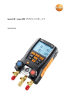
Measurement Principle of NIBP
Oscillometric
Method
This method measures the blood pressure by detecting the pulsation of the artery which is
caused by the contraction of the heart, as the pressure oscillation in the cuff. When the cuff
around the upper arm is fully inflated, blood flow stops but pulsation of the artery continues
and causes oscillation of the pressure in the cuff. As the pressure in the cuff is decreased
slowly, the magnitude of the pressure oscillation in the cuff gradually increases and eventually
reaches a peak. Further decrease of the cuff pressure causes the oscillation to decrease. The relationship between the changes of cuff pressure and its oscillation is stored in memory and used
to determine blood pressure. Namely, cuff pressure when the oscillation increases rapidly is
taken as the systolic pressure, and that when the oscillation decreases rapidly is taken as the
diastolic pressure. Cuff pressure when the oscillation reaches a peak is taken as the mean arterial pressure (MAP).
The oscillometric method does not determine blood pressure instantaneously unlike the auscultatory method and microphone type automatic blood pressure monitor, but determines it from
the curves of the changes of the pressure and its oscillation as described above. This feature
gives it antinoise characteristics as it is not affected by external noise or electric surgical units.
KOROTKOV SOUNDS
MAP
S
to
ys
lic
Di
as
tol
ic
RADIAL PULSE
Comparison among the auscultatory, oscillometric and
palpatory methods of measuring blood pressures.
SOURCE: MEASUREMENT OF BLOOD PRESSURE BY
L.A.GEDDES
– 14 – Outline
02_outline
Page 14
06.8.23, 1:51 PM
Adobe PageMaker 6.5J/PPC
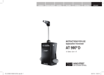
The unit displays an NIBP oscillation graph after each measurement.
Time
➞
Display of the
Oscillation Graph
(Change Patterns
of Pulses)
➞
Pulse Strength
Absolute Amplitude
of the Oscillation
Validation with the
Graphic Waveform
(Change Patterns
of Pulses)
The reliability of measurement results can be checked based on the display of the graphic
Good Measurement
The display below is a mountain shape and reliability of the measurement is high without
waveforms. If there are any doubts about measurement results, check the graphic waveforms.
noise such as motion artifact.
Low Reliability of
Measurement
The display below is not mountain shaped. Noise (motion artifact) has interfered with the
measurement.
Signal that can be considered as
noise.
From the graphic waveform, it can be
considered that the blood pressure
reading was faulty.
Outline
02_outline
Page 15
06.8.23, 1:51 PM
– 15 –
Adobe PageMaker 6.5J/PPC
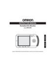
Outline of TU-100 (only for VP-2000)
About the product
The TU-100 is a device that uses the tonometry method to measure pulse waveforms. Connect
it to the BP-203RPEII for operation.
Pulse wave detection
The TU-100 and tonometric sensors employ the tonometry method for pulse wave detection.
By the tonometric method, the pressure pulse wave sensor pushes on the artery so an area of
the artery is flattened. When the wall of the blood vessel is flat, the inner pressure of the artery
is communicated directly to the pressure sensor. The pressure sensor contains a row of 15 elements. The main unit of the BP-203RPEII analyzes the signal from the pressure sensor, and
from the 15 elements selects those in the most suitable position. The pulse pressure measurements from those elements are used in analysis.
Sensor frame
Pressure
Pressure sensor elements
Skin
Arterial wall
Sensor area with 15 elements in a row
– 16 – Outline
02_outline
Page 16
06.8.23, 1:51 PM
Adobe PageMaker 6.5J/PPC
CAP/FAP SENSOR
(Carotid Arterial Pulse,
Femoral Arterial Pulse)
The SENSOR is primarily used on the tonometric sensor head for measurement of large arterial pulse waves, but it can be applied to other areas.
Tonometric sensor head
Please equip with a protective cap
when not in use.
SPACER (Thick)
SPACER (Thin)
The SENSOR can be pressed down using the appropriate pressure, if an attached spacer is
inserted.
Use of a spacer stabilizes inclination.
Outline
02_outline
Page 17
06.8.23, 1:51 PM
– 17 –
Adobe PageMaker 6.5J/PPC
The thicker SPACER is used for subjects with average weight.
The thinner SPACER is used for subjects with avobe average weight.
If the BELT LOOP is attached to the FAP SENSOR, it can be fixed to a strap.
The SENSOR head is made to be very precise and delicate.
Applying undue strength or treating it roughly may cause damage.
Please equip with a protective cap after using FAP SENSOR, and store
it in a secure location.
– 18 – Outline
02_outline
Page 18
06.8.23, 1:51 PM
Adobe PageMaker 6.5J/PPC
Configuration
This device includes the following components. Verify before using.
1. BP-203RPE II Main unit
2. BP-203RPE II API unit
3. TU-100 (only for VP-2000)
4. Laser printer
5. Trolley ST-100A(VP-1000), ST-200A(VP-2000)
6. PCG sensor
7. ECG clip
8. Cuffs in the rear tray, 1 set regular size, 1 set large size (Ankle+Brachial)
9. Operation manual
6. PCG sensor
7. ECG clip
3. TU-100
In the trolley
(VP-2000)
1. BP-203RPE II
Main unit
Main power supply switch
2. BP-203RPE II
API unit
(enclosed in
the trolley)
8. Cuffs
in the rear tray
4. Laser printer
5. Trolley
ST-200A (VP-2000)
ST-100A (VP-1000)
The appearance of the system is subject to change without the prior notice.
Outline
02_outline
Page 19
06.9.16, 5:32 PM
– 19 –
Adobe PageMaker 6.5J/PPC
■ Use only authorized accessories and options in order to avoid problems.
Standard Accessories
ECG ELECTRODES CLIP
PCG SENSOR
13cm STANDARD BRACHIAL CUFFS
15cm LARGE BRACHIAL CUFFS
CUFF HOSE × 2
13cm STANDARD ANKLE CUFFS
15cm LARGE ANKLE CUFFS
SENSOR CABLE UNIT
(ANKLE CUFF HOSE)
PCG SENSOR WEIGHT
Optional Accessories
SENSOR GEL PACK 101S
20 packs
GROUNDING WIRE
VELCRO SET
– 20 – Outline
02_outline
Page 20
06.8.23, 1:51 PM
Adobe PageMaker 6.5J/PPC
Identification
Whole unit
Name of each part and concise functions are described.
Brachial Cuff
API Unit
Ankle Cuffs
Internal communication cable
ECG Clip
TU Data Cable
TU-100
JOG Dial
Start SW.
Stop SW.
Alarm mute SW.
Function SW.
PCG Sensor
CAP sensor
Main Unit
FAP sensor
TU-100 is a optional unit for VP-1000
Color LCD
Printer
Outline
02_outline
Page 21
06.8.23, 1:51 PM
– 21 –
Adobe PageMaker 6.5J/PPC
Main unit rear view
230V∼
50/60Hz
23VA
RS-232
PCG
A
ECG
250V T0.5AH
T0.5AH
ECG : Connector for the ECG cable.
PCG : Connector for the PCG sensor.
A
: Connector to the API unit.
: Connector for the printer cable.
RS-232 : Serial communication port
Power switch : Always leave it On.*
AC Inlet : Connector for AC power cord.
: Fuse. Please contact our customer service center
when fuses are blown.
API unit rear view
SB
M
TU
L
PPG
R
PPG (R) : Connector for the PPG (R) sensor.
(as an option)
230V∼ 50/60Hz 45VA
RA
TUV
Rheinland
Product Safety
0123
250V T1AH
LA
20 0 2
Gepruftes Medizinprodukt
Approved medical device
PPG (L) : Connector for the PPG (L) sensor.
(as an option)
Freiwillige Produktprufung
SB
EU representative:
COLIN EUROPE SARL
9,Rue de l'Industrie
92400 Courbevoie,France
TU: Connector to the TU-100.
SB: Connector for the L/R ankle cuff signal cable.
M : Connector to the main unit.
RA : Connector for the right brachial cuff hose.
LA : Connector for the left brachial cuff hose.
SB : Connector for the L/R ankle cuff hose.
Power switch: Leave it ON.*
AC Inlet: Connector for AC power cord.
: Fuse. Please contact our customer service center
when fuses are blown.
* Power switch: To turn power on or off, use the
main power switch on the trolley. Refer to page 19
for its location.
– 22 – Outline
02_outline
Page 22
06.8.23, 1:51 PM
Adobe PageMaker 6.5J/PPC
TU-100 rear view
250V T0.5AH
230V∼ 50/60Hz 14VA
Pulse Wave Unit
TU-100
Type230
SN
Manufactured by COLIN CORPORATION
API
CAP
FAP
2007-1,Hayashi,Komaki-city,
Aichi-Pref.,485-8501 JAPAN
MADE IN JAPAN
FAP : Connector for the FAP sensor.
CAP : Connector for the CAP sensor.
API : Connector for the API unit.
Power switch: Leave it ON.
(To turn power on or off, use the main power switch on the stand.
Refer to page 28 for its location.)
: Fuse. Please contact your local distributor when
fuses are blown.
AC Inlet : Connect the power cord.
Please be sure to turn off the main power switch, before removing
or connecting each unit and sensors. Not doing so may cause electric shock or device failure.
Outline
02_outline
Page 23
06.8.23, 1:51 PM
– 23 –
Adobe PageMaker 6.5J/PPC
Meaning of the Symbols
Meaning of the symbols on the front panel
Measurement START switch
Measurement STOP switch
Alarm mute
Meaning of the symbols on the rear and side panel
Refer to manual
Type BF:
Classification by leakage current levels
with defibrillation protection.
Type CF:
Classification by leakage current levels
with defibrillation protected.
Class II Equipment
CF
Compact Fllash memory card
BRACHIAL CUFF
INPUT
OUTPUT
– 24 – Outline
02_outline
Page 24
06.8.23, 1:51 PM
Adobe PageMaker 6.5J/PPC
Jog Dial and Function Switch
Jog dial can be turned and pushed, to select and edit.
Turn and Push
Start Switch
Stop Switch
F3
F2
F1
The function switch’s operation is as labeled on
LCD screen.
F1
F2
F3
Function switch
Display of its function
Outline
02_outline
Page 25
06.8.23, 1:51 PM
– 25 –
Adobe PageMaker 6.5J/PPC
Initial Screen
The initial screen is displayed soon after power is switched on.
Menu (F1)
Meas. (F3)
• To perform a test, press [Meas. (F3)].
For test procedures and results, see “Measurement Procedure” (page 31).
• To make basic device settings or to process past test data, press [Menu (F1)].
For details, see “Settings” (page 77).
– 26 – Outline
02_outline
Page 26
06.8.23, 1:51 PM
Adobe PageMaker 6.5J/PPC
Installation
Potential hazard
Do not use this system in the presence of a flammable
anesthetics or in a hyperbaric chamber or oxygen tent.
Method of installation
The BP-203RPE II and TU-100 are designed to
mount to the supplied trolley ST-200A. The
authorized service personnel of Omron Healthcare
Co. or an authorized distributor will assemble and
install this system.
The device shall be setup by the bed side .
Air hoses and cable assemblies shall be put in
undisturbed place or shall be fixed to a bed with
velcro strips
Caster wheel
Please lock the casters when the device is in
use and unlock when moving the system.
Caution to the place of installation
The following locations are not suitable for installing the unit:
■ A location where the system may be splashed with any liquid or potential
contact with steam.
■ A location where direct sunlight is on the unit.
Cautions for installation
■ Do not put heavy materials on this unit.
It may become out of balance and fall. Falling object may become the cause
of an injury.
Caution during transfer
■ Turn off, unplug the AC, and remove the sensors from the patient before
transfer.
■ Unlock the stand before transfer.
■ Please take a special care for the stand not to fall due to unstable balance
when you move the stand without printer loaded.
Outline
02_outline
Page 27
06.8.23, 1:51 PM
– 27 –
Adobe PageMaker 6.5J/PPC
Power On Procedure
Cautions for Tonometric Sensor (CAP / FAP sensor) for VP-2000
■ Be sure to turn off the Power when Tonometric Sensor is plugged in /
pulled out of TU-100,or the internal circuit of Sensor may break down.
Accidentally plugged in / pulled out with power on, turn Power off and
on again for a correct measurement.
With the trolley
To turn on the power, use the Main power supply switch on the left side of the trolley.
MAIN POWER
SUPPLY SWITCH
In case of “No Power”, please verify that unit power switches are “ON” for the TU-100, API
Unit and MAIN Unit in order.
When Power of API Unit or TU-100 is turned off during operation, "Communication Error",
as System error, will be displayed on the screen. In this case, power cycle each Unit again, in
accordance with the procedure above.
– 28 – Outline
02_outline
Page 28
06.8.23, 1:51 PM
Adobe PageMaker 6.5J/PPC
Check before Use
For safe and proper use, the machine has to be checked
before use.
Prior to daily use, the following points should be checked:
Before turning the
power ON
Appearance
■ No deformation due to falling?
■ Is the unit clean?
■ Is the unit wet?
Power Cord
■ Is the power cord secure at the main unit connector?
■ No heavy object placed on the power cord?
■ No damage to the power cord? (No core showing? Cut?)
■ Is the power cord connected to an outlet with a grounding wire?
Printer
■ Is the printer paper enough?
After turning the
power ON
Appearance
■ No smoke or abnormal smell?
■ No abnormal noise?
Time Indication
■ Is the clock correct?
NIBP
■ Is the proper sized cuff for the patient’s arm and ankle prepared?
■ Are the connections of the cuff hose and cuff secure?
ECG and PCG
■ Are the ECG electrodes and PCG sensor gels new?
Turn ON/OFF
the device
Use the main power switch located on the stand to turn ON/OFF the device.
When turning ON the device;
■ Do not attach the ECG clips to the patient;
■ Do not touch or move the ECG clips.
System information
In contacting our customer service and referring to manuals, please note the system version.
The system version can be checked in the procedure below.
In accordance with Menu Screen,
■ Select Menu
■ select "5.System Information"
■ press jog dial.
■ System version number is indicated on the display
Outline
02_outline
Page 29
06.8.23, 1:51 PM
– 29 –
Adobe PageMaker 6.5J/PPC
Memo
– 30 – Outline
02_outline
Page 30
06.8.23, 1:51 PM
Adobe PageMaker 6.5J/PPC
Measurement Procedure
Measurement procedure is different when tonometric sensor is used. Please follow the flow chart below.
Flow of this chapter (Contents)
START
*When using tonometric sensor
(only for VP-2000)
Attaching the brachial cuff, ankle cuff, ECG clip, and PCG sensor
........... page 32
Operation procedures when not using tonometric
sensors or when the system is VP-1000
.................. page 42
Operation procedures for post exercise mode.
Only when operation continuing exercise load measurement
.................. page 57
END
*Operation procedures for using tonometric sensors
.................. page 64
END
To avoid any accident, read WARNING and CAUTIONS indicated in
"Check Before Use" carefully, before the operation.
Measurement Procedure
03a_measure
Page 31
06.8.23, 1:53 PM
– 31 –
Adobe PageMaker 6.5J/PPC
Application of the BRACHIAL CUFF
The STANDARD BRACHIAL CUFF included with the VP-1000/2000 can be used to take the
Cuff Selection
measurement of a patient whose arm circumference is 23 cm to 38 cm.
Choosing an appropriate cuff for the patient is necessary to obtain an accurate measurement.
Choose a cuff appropriate for the patient by referring to the table below. To attach to the cuff
hose, insert the hose and turn it clockwise to lock.
Name
Arm circumference
(cm)
Bladder width
(cm)
CUFF No. 20, 21 Standard accessory
23 to 33
13
CUFF No. 7, 8
Standard accessory
17 to 26
10
CUFF No. 5, 6
Optional accessory
32 to 38
15
Choose the appropriate cuff to avoid any error caused by gap between
cuff and arm in the measurements.
If the cuff used is too large, the blood pressure measurement may be
lower than the actual value. If the cuff used is too small, the blood pressure measurement may be higher than the actual value.
Check that there is no looseness in the connection area. If there is an air
leakage, correct measurements can not be taken.
Apply the BRACHIAL CUFF to the upper arm of the patient. The BRACHIAL CUFF are different for the right and left arms. Do not apply the wrong one.
■ If the patient has an internal shunt for dialysis, do not apply the cuff to
the arm with the shunt. Measure only at the arm that does not have
an internal shunt.
Request
■ When applying the BRACHIAL CUFF to one arm only, select "Right Bra. (or Left Bra.) +
Both Ank.". For details, see "Entering Measurement Conditions" in "Patient Information
Input" (page 45).
■ Position the BRACHIAL CUFF at a height equal to that of the patient's heart.
Note
■ If the patient has an irregular pulse, it may be impossible to measure accurately unless a
regular pulse wave is obtained.
■ If there is shivering or cramping, an accurate pressure value may be impossible to obtain.
Caution!
Wrap the cuff around a bare arm or thin clothing. Wrapping the cuff around thick clothing
or rolled up sleeves may cause a large margin of error in the blood pressure measurement.
– 32 – Measurement Procedure
03a_measure
Page 32
06.8.24, 0:25 PM
Adobe PageMaker 6.5J/PPC
Propercuff
placement
1. When required, wipe the application site clean with diluted disinfectant alcohol. Place the
patient in a supine position. The brachial artery runs down the inside of the arm. Attach the
cuff so that the artery position mark aligns with the artery.
Brachial artery
Artery position mark
■ When applying the cuff above clothing, pull the clothing so that it does not bunch up on
the side of the artery 3.
If the cuff is wrapped around the arm with clothing bunched up at the artery site, the
blood pressure will measure higher than the actual value.
3
Measurement Procedure
03a_measure
Page 33
06.8.23, 1:53 PM
– 33 –
Adobe PageMaker 6.5J/PPC
2. As a standard for deciding the up-down position, align the elbow hinge mark of the arm
cuff with the elbow hinge line.
Elbow hinge line
Elbow hinge mark
3. Wrap the cuff around the arm. At this time, be sure that the index line is inside the range
shown by the arrow mark.
If the mark does not go inside the range, use a cuff of another size.
Index line
Range shown by the arrow mark
4. Wrap the cuff snugly so that 2 fingers can be placed between the cuff and the arm.
■ Ensure there is no kink or closing of cuff and/or hose.
When there is kink or closing in the cuff and/or hose, air is not let out
from the cuff. This may result in bad blood circulation in the arm,
causing peripheral functional disorder.
– 34 – Measurement Procedure
03a_measure
Page 34
06.8.23, 1:53 PM
Adobe PageMaker 6.5J/PPC
Application of the ANKLE CUFF
Choosing an appropriate cuff for the patient is necessary to get an accurate measurement.
Cuff Selection
Choose a cuff appropriate for the patient according by referring to the table below. To attach to
the CUFF HOSE, insert the hose and turn it clockwise to lock.
Name
Ankle circumference
(cm)
Bladder width
(cm)
CUFF No. 22, 23 Standard accessory
CUFF No. 25, 26 Standard accessory
23 to 33
16 to 25
13
10
Choose the appropriate cuff to avoid any error caused by gap between
cuff and ankle in the measurements.
If the cuff used is too large, the blood pressure measurement may be
lower than the actual value. If the cuff used is too small, the blood pressure measurement may be higher than the actual value.
Check that there is no looseness in the connection area. If there is an air
leakage, correct measurements can not be taken.
Apply the ankle cuff to the ankle of the patient. The ANKLE CUFF are different for the right
and left ankles. Be careful to attach the correct cuff with the correct location.
Do not use the ANKLE CUFF for patients that suffer from deep phlebothrombosis in the lower leg.
Note
■ If the patient has an irregular pulse, it may be impossible to measure accurately unless a
regular pulse wave is obtained.
■ If there is shivering or cramping, an accurate pressure value may be impossible to obtain.
Caution!
The dual chamber cuff has a special distal sensor cuff for the purpose of detecting the pulse.
Wrap the cuff so that the sensor cuff is in contact with the posterior tibial artery of the ankle.
Posterior
tibial artery
Sensor cuff
Measurement Procedure
03a_measure
Page 35
06.8.23, 1:53 PM
– 35 –
Adobe PageMaker 6.5J/PPC
Propercuff
placement
1. Remove socks or stockings. There are left ankle cuff and right ANKLE CUFF. Put cuffs
on the correct ankle respectively. Put the hose area on the inside ankle. When required,
wipe the application site clean with diluted disinfecting alcohol.
2. Apply the cuff to the ankle. Position the ankle cuff so that the sensor cuff 2 on the inside is
against the posterior tibial artery 1.
1
2
3. Align the mark at the bottom of the cuff 3 with the top of the ankle protrusion on the inside of the leg. Do not allow the cuff to lie over the ankle.
3
■ If the cuff position shifts, the cuff will not detect the posterior tibial artery, and accurate
measurement will be impossible. Be especially careful for patients with thin legs.
4. Wrap the belt on the ankle side 4, then wrap the calf-side belt 5. Allow enough slack to
insert one finger between the leg and the cuff.
4
5
– 36 – Measurement Procedure
03a_measure
Page 36
06.8.23, 1:53 PM
Adobe PageMaker 6.5J/PPC
The ANKLE CUFF can be used to take the measurements of patients with an ankle circumference of 23 cm to 33 cm. If a section of the index line 6 can be seen through the cuff’s window 7, that measurements can be taken.
6
7
5. Make sure the cuff does not shift downward. The cuff should stop at the top of the protruding ankle bone.
Measurement Procedure
03a_measure
Page 37
06.8.23, 1:53 PM
– 37 –
Adobe PageMaker 6.5J/PPC
Application of ECG ELECTRODES CLIP
Apply the ECG ELECTRODES CLIP to the patient's wrists. There are different clips for the right and left arms. Do not
apply the wrong one. When necessary, wipe the application site with diluted antiseptic alcohol or a similar product.
Attaching electrodes
to ECG ELECTRODES
CLIPS
Press and hold the button placed on the side of the ECG ELECTRODES CLIP and insert one
electrode to the right ECG ELECTRODES CLIP. Release the button to fix the electrode to the
clip. Repeat these steps with the left ECG ELECTRODES CLIP. Then, remove the protection
sheets from all 3 electrodes.
Use only Ag/AgCl type monitaring electrode.
2.
1.
Application of ECG
ELECTRODES
CLIP
Application of electrodes:
■ Do prep to the equipment surface as necessity.
■ The sensor that has two electrodes is placed on the left side.
■ Put electrodes on the inside of arms.
■ Make sure to adhere electrodes closely.
Right ECG ELECTRODES CLIP
Left ECG ELECTRODES CLIP
(with one electrode)
(with two electrodes)
– 38 – Measurement Procedure
03a_measure
Page 38
06.8.23, 1:53 PM
Adobe PageMaker 6.5J/PPC
■ It would be impossible to inspect STI because of mismonitoring
of R-wave if the patient uses pace maker.
■ It would be impossible to correctly inspect PWV and STI because of
improper reading of waves, if the patient has medical history of arrhythmia.
■ The conductive parts of ELECTRODES and associated connectors for APPLIED PARTS, including the NEUTRAL ELECTRODE,
should not contact other conductive parts including earth.
■ Even when reusing an ECG ELECTRODE CLIPS for the same patient, replace the electrodes with new ones every time if the skin
is moist, injured, or infected.
■ As a rule, the ECG ELECTRODE CLIPS are applied to both arms,
but occasionally the ECG signal will be weak and measurement
difficult. When this happens, place the electrodes for the left arm
on top of those for the right arm (secondary induction) and
measure.
■ The expiration date for wrist electrodes is printed on their packaging. If the electrodes are used after the expiration date has
passed, they may be dry, causing inaccurate measurement. Always use electrodes before their expiration date.
■ Cautions about ECG ELECTRODES
• If they are dry or worn, measurement cannot be operated accurately.
• The wrist ECG ELECTRODE CLIPS electrodes are disposable. Reuse is possible only if they are being used on the same patient. Replace with new electrodes after application to the patient with damp,
trauma, infection disease etc.
Measurement Procedure
03a_measure
Page 39
06.8.23, 1:53 PM
– 39 –
Adobe PageMaker 6.5J/PPC
Application of PCG SENSOR
Preparation for
PCG
Put (exchange) gel pad to PCG SENSOR.
1. Take off the protective sheet 1 (light
blue) and put it to the sensor 2.
2
Application of
sensor
1
2. Strip clear cover sheet 3 which is on gel
pad side.
3
Pay attention to the following:
■ Placement of PCG SENSOR is normally at the left edge of 4th-rib-case 4 as indicated below. Also, it is possible to place the sensor at the middle of the 3rd-rib-case 5. Or the right
edge of 2nd-rib-area 6. Verify proper location by looking at the PCG indicator so that you
can obtain the II sound.
4
6
5
– 40 – Measurement Procedure
03a_measure
Page 40
06.8.23, 1:53 PM
Adobe PageMaker 6.5J/PPC
■ When patients have heart murmur or have abnormal sounds,
accurate heart sound cannot be inspected.
■ When patients generate noise during respiration, the sound cannot be inspected accurately.
■ Do not drop the PCG SENSOR or PCG SENSOR WEIGHT on the
patient. Doing so will cause injury.
■ Cautions about gel pads
• If they are dry or worn, measurements may not taken accurately.
• The PCG SENSOR gel pads are disposable. Reuse is possible only if
they are being used on the same patient. Replace with new sensor
gel pads after application to the patient with damp, trauma, infection
disease etc.
■ Even when reusing the PCG SENSOR part for the same patient,
replace it with a new one every time if the skin is moist, injured,
or infected.
■ The expiration date for the PCG SENSOR part is printed on its
packaging. If the sensor is used after the expiration date has
passed, it may have dried, causing inaccurate measurement. Always use sensors before their expiration date.
Sometimes the screen does not display "PCG: OK" even when the PCG sensor position is
PCG Sensor
Weight
changed. The following are likely causes of this:
• There is thick fat or muscle at the application site that attenuates heart sounds.
• The PCG SENSOR cannot adhere easily to the skin, due to excessive body hair.
• The PCG SENSOR cannot adhere to the skin, due to unevenness of the body surface.
• The PCG SENSOR adheres to the skin at a slant, because the body surface is not level.
These problems can be resolved by using the PCG SENSOR WEIGHT.
1. Place the PCG SENSOR WEIGHT 1 over the PCG SENSOR 2 from above, so that it
covers the sensor.
2
1
• The PCG SENSOR WEIGHT can be placed over clothing.
Request
■ Do not use a weight that has a hole or tear in its surface.
■ If the filling of a weight leaks out, clean it up quickly.
■ Be careful not to damage the surface of the weight with a ballpoint pen or other sharptipped object.
■ If the weight is dampened by sweat or water, wipe it dry right away.
■ Do not wash with water.
Measurement Procedure
03a_measure
Page 41
06.8.23, 1:53 PM
– 41 –
Adobe PageMaker 6.5J/PPC
Measurement Information Input
After turning on the power and applying sensors, enter information about the patient.
The following patient information can be entered:
ID Number
Enter up to 13 numeric characters that will be used for managing patient information.
Patient Information
Enter patient information such as sex and height.
Measurement
Conditions
Enter necessary information related to measurement, such as the basic disease and measurement location.
Take care to avoid mistakes in entering information and numerical values, because this information will be used when the
analysis results are printed out.
– 42 – Measurement Procedure
03a_measure
Page 42
06.8.23, 1:53 PM
Adobe PageMaker 6.5J/PPC
ID Number Input
Enter up to 13 numeric characters that will be used for managing patient information. This section explains the procedure
for entering new information.
Note
■ Once a registered ID is entered, the associated name and other data can be retrieved from
the CompactFlash memory.
■ You can also make settings that allow you to manage information using the ID number. For
details see "User Setting" on page 79.
1. Press [Meas. (F3)] 1.
1
2. The ID Input Screen will be displayed. Enter an ID number for the patient.
Rotate the jog dial until the box highlights the number or letter you wish to enter (2), then
push the job dial to select.
2
■ If you make a mistake, press [CORRECTION (F1)]. One character will be deleted from
the right each time this is pressed.
■ To erase the patient ID, select [NEW ID (F2)] on the screen by pressing the function
switch.
■ To return to the default values, press [Stop Switch].
3. When entry is finished, press [CONFIRM (F3)].
ID Number Input
Conditions
■ Up to 13 characters can be entered for the ID number.
Letters, numbers, and hyphens (-) can be used.
■ ID Number Recognition
If you make a mistake in the number of characters when entering an ID number, it will be
recognized as a different number. For example, "300" and "0300" are recognized as different IDs.
Measurement Procedure
03a_measure
Page 43
06.8.23, 1:53 PM
– 43 –
Adobe PageMaker 6.5J/PPC
Patient Information Input
Enter patient information. The information to be entered is shown in area 1 on the screen below.
1
The following items can be entered:
SEX
Enter the sex.
HEIGHT
This is used when calculating PWV. Enter the correct height in centimeters. The entered height
can range from 120 to 210.
WEIGHT
This is used when calculating the BMI index. Enter in increments of 0.1 kg. The entered
weight can range from 25.0 to 200.9. Weight input can be omitted.
BIRTHDAY
Enter the month, day and year. When entry is complete, the patient's age are displayed.
– 44 – Measurement Procedure
03a_measure
Page 44
06.8.23, 1:53 PM
Adobe PageMaker 6.5J/PPC
Entering Measurement Conditions
Required information such as the measurement site can be entered here. The information to be entered is shown in area 2
on the screen below.
2
The following items can be entered or selected:
Select the default location for measurement. Normally "Both Bra. + Both Ank." is selected.
Meas. Part
For patients who have an internal shunt for dialysis, the cuff will be applied only to the arm
that has no shunt. Select either "Both Bra. + Left Ank." or "Right Bra. + Both Ank." for such
patients.
When using an option such as a pulse wave unit TU-100 unit read the appropriate operation
manual beforehand.
Normally "AUTO" is selected here. This system is set to inflate the cuff and measure the pa-
Pressurized Right
Ank./Left Ank.
tient's blood pressure automatically. If the patient complains of pain caused by inflation, you
can change to an already set lower value for the ankle by pressing [Low Inflation (F2)]. After
that the pressure can be changed within the range of 100 to 280 by rotating the jog dial.
Note
■ If [Low Inflation (F2)] is pressed when the pressure upper limit item is selected, the set
inflation value will be displayed. To return to the original value, press [AUTO Inflation
(F1)].
For more information about the inflation value setting, see "User Setting" (page 79).
Note
■ Set an appropriate upper limit for inflation, using "Maximum Pressure + 60 mmHg" as a
guideline.
■ If the valued entered as the upper limit for inflation pressure is not appropriate, the blood
pressure measurement value will be low, as shown in the diagrams below.
a. Accurate measurement
b. Inaccurate measurement obtained when inflation is not
sufficient
Measurement Procedure
03a_measure
Page 45
06.8.23, 1:53 PM
– 45 –
Adobe PageMaker 6.5J/PPC
Measurement
Times
The device automatically starts the next measurement cycle after waiting for the “Wait Time”
Wait Time
This sets the period between the end of the first measurement and the start of the second meas-
to elapse.
urement. The default is 10 seconds but this can be adjusted in the range of 10 to 120 seconds if
necessary, in consideration of the patient's circulation.
Tonometry
This item is valid when the pulse wave unit TU-100 set (only VP-2000) is installed. For
information about this setting and the measurement procedure, see page 64.
Measurement
Condition Input
Procedure
1. Use the jog dial to select the item to be set.
2. Push the jog dial. The item will be highlighted.
3. Rotate the jog dial and select the desired numeral or selection.
4. Push the jog dial to confirm the selection.
5. Repeat steps 1 to 4 to make other settings.
6. When finished setting, press [CONFIRM (F3)]. The pulse wave display screen will appear.
To cancel settings before finishing, press Stop Switch.
– 46 – Measurement Procedure
03a_measure
Page 46
06.8.23, 1:53 PM
Adobe PageMaker 6.5J/PPC
Screen Display
1
2
3
4
6
5
8
7
1 ECG Message
Displays the ECG status. For information about this display, see "ECG Messages" (page 48).
2 PCG Message
Displays the PCG status. For information about this display, see "PCG Messages" (page 49).
3 Heart Rate
Displays the patient's heart rate.
4 ECG Wave
Displays the ECG wave. If this is not displayed, make sure nothing is disconnected. See
"Application of ECG ELECTRODES CLIP" (page 38).
5 PCG Level
Displays the detected PCG level using four level meters. It is recommended that at least the
third meter be flashing when measurement starts. Measurement can be performed even if
only the second or lower meter is flashing, but accuracy may be reduced. When this happens, adjust the position of the PCG SENSOR or use the PCG SENSOR WEIGHT. See
"Application of PCG SENSOR" (page 40).
6 PCG Wave
Displays the PCG wave.
7 [Pacemaker (F1)]
Press this, turning it ON, when the patient uses a pacemaker.
Note
■ When measurement is finished, the pacemaker setting is reset, returning it to OFF. Turn it
ON each time measurement is performed.
■ The ECG display gain is normally set by an auto-gain function. However, when the pacemaker setting is turned ON, the gain becomes fixed at 10 mm/mV.
8 [Condition (F3)]
Changes the measurement conditions. This is displayed when "Simple Input: ON" is set.
Measurement Procedure
03a_measure
Page 47
06.8.23, 1:53 PM
– 47 –
Adobe PageMaker 6.5J/PPC
ECG Messages
This section details the contents of the ECG messages. When "OK" is not displayed, measurement accuracy may be reduced. Take corrective action according to the content of the message.
Message Content
Status and Corrective Action
OK
ECG is stable. Measurement can begin.
Initializing
Checking the heart's electrical potential. Remain at
rest.
Unstable R-R Interval
• The electrodes are dry or dirty.
Replace with new electrodes (page 38).
• The patient is tensing the arm, causing
electromuscular effects.
Have the patient relax the arm and rest quietly.
• Noise from radio interference is affecting the ECG
waveform.
If a cell phone or other device is operating nearby,
move it farther away.
• Only a weak signal can be obtained from the wrist.
Try placing the ECG ELECTRODES CLIP from
the left wrist on top of the one on the right wrist
(secondary induction).
• Check Electrodes
• No ECG ELECTRODE is placed in the ECG
ELECTRODES CLIP.
Make sure that three wrist electrodes are securely
placed (page 38).
• The ECG ELECTRODE still has its protective
cover.
Remove the protective cover from the ECG ELECTRODE (page 38).
• An ECG CABLE is disconnected.
Make sure that all ECG CABLE are securely connected.
• Check Patient / Electrodes
• R-wave not Detected
– 48 – Measurement Procedure
03a_measure
Page 48
06.8.23, 1:53 PM
Adobe PageMaker 6.5J/PPC
PCG Messages
This section details the contents of the PCG messages. When "OK" is not displayed, measurement will be impossible or accuracy may be reduced. Take corrective action according to the
content of the message.
Message Content
Status and Corrective Action
OK
PCG is stable. Measurement can begin.
Initializing
Checking the heart sound. Remain at rest.
Signal Out of Range
• The sensor has been touched, causing noise.
Remain at rest.
• The PCG SENSOR is not adhering, or the shirt or
other clothing has come under it.
Make sure the PCG SENSOR is correctly adhering
to the skin. If correct adherence cannot be obtained,
use the PCG SENSOR WEIGHT (page 41).
• The PCG SENSOR pad is dry or dirty.
Replace with a new PCG SENSOR pad (page 40).
• The PCG SENSOR has been applied upside down.
Apply the PCG SENSOR correctly.
Weak Signal
A position where three or more level meters are flashing is ideal. Measurement is possible even if two or
less are flashing. However, accuracy of measurement
may be reduced.
Re-position Sensor
• Application site is not suitable.
Position the PCG SENSOR in a better location
(page 40).
• For patients with cardiac murmur or respiratory
noise, it may be difficult to clearly distinguish the
first and second heart sounds. While this may cause
reduction in accuracy, measurement is still possible.
PCG Disconnected
• The PCG cable is disconnected.
Make sure that PCG cable is securely connected.
Measurement Procedure
03a_measure
Page 49
06.8.23, 1:53 PM
– 49 –
Adobe PageMaker 6.5J/PPC
Start of Measurement
Measurement begins.
Note
■ Measurement ends after either one or two measurements. The second measurement is
performed automatically under the following circumstances:
• When blood pressure cannot be accurately measured.
1. Check whether the screen display shows "ECG: OK" and "PCG: OK."
2. Press [Start Switch]. Measurement begins.
– 50 – Measurement Procedure
03a_measure
Page 50
06.8.23, 1:53 PM
Adobe PageMaker 6.5J/PPC
■ Performing second measurement
When first measurement is finished, a standby time counter is automatically displayed.
When the count is finished, the second measurement begins.
3. When the measurement is finished, the results are displayed on the screen, and the results
are printed out.
• If "No. of Print" is turned OFF, no printing will be performed. Results will be displayed on
the screen only.
See "User Setting" "No. of Print" (page 82).
• For the layout of the results screen, see page 53. For the layout of the inspection results
sheet, see "Printing" (page 54).
Measurement Procedure
03a_measure
Page 51
06.8.23, 1:53 PM
– 51 –
Adobe PageMaker 6.5J/PPC
■ Printing additional results
Use the jog dial to select the print sheet type from the results screen, then press [Print (F3)].
Note
■ When performing the recovery measurement after the continuous exercise measurement,
press [Post Exer. Mode (F1)]. For details, see "Exercise Measurement" (page 57).
4. To end the measurement, press [Stop Switch].
Returns to the screen after the measurement.
5. Remove the sensors from the patient.
Request
■ The ECG ELECTRODES CLIP and PCG SENSOR can be reused for the same patient. Do
not use for another patient.
– 52 – Measurement Procedure
03a_measure
Page 52
06.8.23, 1:53 PM
Adobe PageMaker 6.5J/PPC
Results
This section describes the layout of the measurement results screen that is displayed when a measurement finishes. For information about printing out the measurement results, see "Printing" (page 54).
2
1
3
4
6
5
7
8
1 Pressure measurement values
Displays the blood pressure values for each measurement part. The fields will be blank for any parts that were not measured. If the area could not be measured during the second measurement, the first measurement value will be displayed as
is. If measurement was not successful both the first and second times, an error message will be displayed.
2 ABI
Displays right and left ABI.
When blood pressure is measured at both arms, the ABI is calculated from the highest brachial pressure value.
3 baPWV
This displays the PWV value calculated from the time period from the start of the brachial pulse wave to the start of
the ankle pulse wave.
4 HR
Displays the heart rate from the R-R interval obtained from ECG.
5 Graph
This graph shows the relationship between baPWV and ABI.
6 Simultaneous phase display line
This line expresses simultaneous phase measurement. If the time phases do not match due to remeasurement or
other reasons, this line is not displayed.
7 [Post Exer. mode (F1)]
Press this when successive exercise measurements will be performed.
8 [Print (F3)]
Press this to print additional copies of the analysis result sheet. The number of copies can be set with the jog dial.
Do not turn off the power during printing. CF memory may be broken.
Measurement Procedure
03a_measure
Page 53
06.8.23, 1:53 PM
– 53 –
Adobe PageMaker 6.5J/PPC
Printing
Standard
Prints the analysis results saved on the medical device that performed.
1
3
4
5
2
6
0
7
A
8
8
9
1 Patient information
Shows the patient information entered into the patient information input screen.
2 Heart rate
Shows the measured heart rate.
3 ECG
Printout of the ECG waveform.
4 PCG
Printout of the PCG waveform.
5 PVR waveform
Shows the pulse wave obtained from the measurement. Because the amplitude of these results is calibrated from the measured blood pressure value, the amplitude may be different
than that shown on the screen.
– 54 – Measurement Procedure
03a_measure
Page 54
06.8.23, 1:53 PM
Adobe PageMaker 6.5J/PPC
6 %MAP
This value is one of the pulse waveform indexes that is calculated from the blood pressure
values. It expresses, as a percentage, a value from the area of the wave form (P2) divided
by the amplitude of the pulse (P1). This value is calculated with the following formula:
%MAP = P2/P1 ¥ 100 (%)
PP
a. Soft (i.e. 45%)
b. Hard (i.e. 38%) c. Constricted (i.e. 50%)
7 Blood pressure values
The shows the blood pressure values for the left and right arm and left and right ankle.
If measurement was not possible, a message will be displayed. For information about the
contents of the message and corrective action, see "Error Messages" (page 88).
■ When the blood pressure values for the right and left upper arms
are greater than 16 mmHg, the highest blood pressure from the
lower side is shaded.
■ If a measured value is in parentheses, this indicates that it is a
reference value only. This is because the accuracy of that value
was low for some reason.
8 PWV
This gives the baPWV value. It measures the start of the brachial pulse wave to the start of
the ankle pulse wave.
9 ABI value
Shows the right and left ABI values.
Measurement Procedure
03a_measure
Page 55
06.8.23, 1:53 PM
– 55 –
Adobe PageMaker 6.5J/PPC
0 Pulsatile variation graph
This graph shows the pulsatile variation obtained from each cuff.
Synchronization line: This line is not printed if synchronized measurement was not possible.
Inflation upper limit: If the inflation upper limit is set
to anything besides "AUTO," that setting is printed
here.
When "Estimate" or "First Measurement" is displayed,
accuracy may be poor.
The part marked with a black dot is the highest blood pressure value.
This will not be printed if measurement was not possible.
This level meter shows the size of the pulse wave.
Border: when constriction of the upper arm or ankle is suspected, this border will be
printed with a thicker line for emphasis.
A Observation
Gives observations based on the test results.
– 56 – Measurement Procedure
03a_measure
Page 56
06.8.23, 1:53 PM
Adobe PageMaker 6.5J/PPC
Exercise Measurement
This function is used when the heart is given a set amount of exercise on a treadmill or similar device and then blood pressure is measured. After exercise is finished, the ECG and blood pressure gradually return to their status at rest. By measuring this process (recovery), abnormalities can be discovered that would be hidden at rest.
■ The amount of exercise given to the patient must be determined in
consultation with a physician. Furthermore, during the exercise, always pay close attention to the patient's condition.
■ When giving an exercise test to a patient with heart disease, a physician must attend and sufficient emergency measures must be prepared.
Note
■ Measurement can be performed for a maximum of 60 minutes after exercise.
Exercise Measurement Procedure
1. Take a normal measurement with the patient at rest (page 42).
2. Remove the ANKLE CUFF, ECG ELECTRODES CLIP, and PCG SENSOR from the patient.
■ The BRACHIAL CUFF can be left on the patient and disconnected from the CUFF
HOSE as shown in the diagram below.
3. When the measurement results screen is displayed, press [Post Exer.Mode (F1)].
Measurement Procedure
03a_measure
Page 57
06.8.23, 1:53 PM
– 57 –
Adobe PageMaker 6.5J/PPC
4. Set up the exercise. Press [Stress (F1)] to display the setup screen. The wave display screen
will appear.
5. Select an exercise item using the jog dial, and input it. The exercise setup screen will be
displayed.
Note
■ The following items can be set:
• Distance
Enter the distance to be walked.
• Degree
Enter the treadmill's incline angle.
• Speed
Enter the treadmill's speed.
• Interval
Enter the measurement interval for after the exercise.
• Meas. Part
Enter the body part where blood pressure will be measured.
– 58 – Measurement Procedure
03a_measure
Page 58
06.8.23, 1:53 PM
Adobe PageMaker 6.5J/PPC
6. When entry is finished, press [Screen (F2)] to switch to the ECG/PCG wave screen.
7. Start the patient's exercise.
8. When exercise is finished, immediately apply the ANKLE CUFF, ECG ELECTRODES
CLIP, and PCG SENSOR. Connect the BRACHIAL CUFF to the CUFF HOSE.
■ Connect the BRACHIAL CUFF to the CUFF HOSE as shown in the diagram below.
9. Check that "ECG: OK" and "PCG: OK" are displayed on the screen.
10. Press [Meas. Start (F3)] or Start Switch.
Measurement begins.
Measurement Procedure
03a_measure
Page 59
06.8.23, 1:53 PM
– 59 –
Adobe PageMaker 6.5J/PPC
11. Press [Screen (F2)] to display the list screen.
For details on displaying this screen, see "Screen Display During Measurement" (page 61).
12. Check the "RR" (recovery ratio) value. If it exceeds 1.0, measurement will end.
Press [Meas. End (F3)].
13. Press [End (F2)].
When measurement ends, the measurement results "recovery ratio" will be printed.
■ For details about "recovery ratio", see "Example of printout" (page 63).
– 60 – Measurement Procedure
03a_measure
Page 60
06.8.23, 1:53 PM
Adobe PageMaker 6.5J/PPC
Screen Display During Measurement
During measurement, you can display results on the next screen by pressing [Screen (F2)]. Each time you press [Screen
(F2)], the display cycles through the following sequence: "List Screen", "Trend Screen" and "Previous Data Screen".
List Screen
Display a list of measurement results, along with the elapsed time.
1
2
3
4
1 Interval
Counts the standby time until the next measurement.
2 SYS
Shows the maximum blood pressure value.
3 ABI
Shows the ABI value.
4 RR
Recovery ratio is the ratio of measured ABI to ABI at rest. ABI of resting measurement is
1.
Measurement Procedure
03a_measure
Page 61
06.8.23, 1:53 PM
– 61 –
Adobe PageMaker 6.5J/PPC
Trend screen
Graphs the trend of ABI values over the elapsed time.
Previous data
screen
Displays the most recently measured values and graphs the pulsatile variation.
– 62 – Measurement Procedure
03a_measure
Page 62
06.8.23, 1:53 PM
Adobe PageMaker 6.5J/PPC
Example of printout
This device will automatically printout the results as follows, after completing the measurement.
1
2
3
4
5
6
1 Patient information
Prints the patient information.
2 Trend chart
Graphs the trend in ABI values over the elapsed time.
3 List data
Displays a list of measurement results, along with the elapsed time.
"R" in the "Measurement time" column indicates a measurement made at rest. "P" indicates
a post-exercise measurement.
4 ( ) shows unsuccessful measurement.
5 Exercise Condition
Prints information about the exercise conditions.
6 Comment
Prints remarks about the measurements.
Do not turn off the power during printing. CF memory may be broken.
Measurement Procedure
03a_measure
Page 63
06.8.23, 1:53 PM
– 63 –
Adobe PageMaker 6.5J/PPC
Measurement Procedures VP-2000 (with tonometric sensor)
1. Sensor Attachment
(except tonometry sensors)
Have the patient lay in the supine position, then attach the ECG ELECTRODES CLIPS, PCG
2. Entering Information
Input the patient information and the measurement condition. (page 42)
SENSOR and the CUFF to the patient. (page 32)
Setting procedure for "Tonometry" is as follows;
Tonometry:
When the examination is conducted with using Tonometric sensor, select the
type of Tonometric sensors.
Blank ······················· No use of Tonometric sensor.
Carotid ····················· Only CAP sensor is used.
Carotid + Femoral ··· Both of CAP sensor and FAP sensor are used.
– 64 – Measurement Procedure
03b_measure
Page 64
06.8.23, 1:53 PM
Adobe PageMaker 6.5J/PPC
3. Confirmation of
ECG and PCG
signals
Verify the stability of ECG and PCG signal on the following screen.
Signal's Status:
Refer to pages 48 and 49 when ECG signal or PCG signal is not displayed "OK".
PCG Level meter:
Make sure that three or more blocks of light are on.
Pacemaker:
"Pacemaker" is on when the patient uses the pacemaker.
(page 47)
It is possible to start a measurement without the "OK" display,but the accuracy
may be decreased.
Measurement Procedure
03b_measure
Page 65
06.8.23, 1:53 PM
– 65 –
Adobe PageMaker 6.5J/PPC
4. Attaching the
FAP SENSOR
FAP SENSOR is a optional and only when the sensor is selected in "User setting screen".
Feel for the pulse
Touch the femoral artery, and find a place where the pulse is easily felt.
Attach the sensor
Place the sensor on the area of the femoral artery found by touch above. Apply a constant pressure by hand while taking the measurement. The sensor should be applied directly to the skin.
■ Apply a constant pressure while taking the measurement. This will
have an influence on the precision of the measurement.
■ If a patient is having convulsions or with a venous pulse, it may not
be able to take a correct carotid pulse waveform.
■ If a patient has an arrhythmia, the PWV may not be able to be correctly measured due to insufficient number of pulsation.
■ The sensor head is made to be very precise and delicate.
Applying undue strength or treating it roughly may cause damage.
– 66 – Measurement Procedure
03b_measure
Page 66
06.8.23, 1:53 PM
Adobe PageMaker 6.5J/PPC
Using the belt
The belt can be used to hold the sensor in position. To use the belt, the belt loop has to be
attached to the rear of sensor.
Stable, firm pressure can be obtained for the measurement by using the belt. The hold down
pressure can be measured by the tonogram.
Measurement Procedure
03b_measure
Page 67
06.8.23, 1:53 PM
– 67 –
Adobe PageMaker 6.5J/PPC
5. Confirmation of
FAP signals
Check the stability of each signal.
Pressure:
The pressure as gained by each sensor element.
Tonogram:
Should ideally form a mountain shape. Yellow lines show the
selected sensor elements. Attach the sensor so that the yellow
lines are in the middle, insofar as possible.
If "OK" is not indicated at each signal's status, check the points below and make adjustments
until the OK message is displayed.
Screen message
Countermeasure
FAP: Initializing
FAP: Weak Signal
■ Please wait for a while.
FAP:
FAP:
FAP:
FAP:
FAP:
■ Change the attached position of the sensor.
■ Change the attached position to the position with the
strong pulse.
Ungetable Signal
Time out
Adjust Sliding Sensor Head
Move sensor toward A-side
Move sensor toward B-side
NOTE
■ Check ECG.
■ Reposition the sensor as instructed.
■ The tonogram cannot be displayed when ECG electrodes are not attached to a
patient.
– 68 – Measurement Procedure
03b_measure
Page 68
06.8.23, 1:53 PM
Adobe PageMaker 6.5J/PPC
6. Using the
Hand-held
CAP SENSOR
When using the a Hand-held CAP SENSOR on the patient’s neck, pay attention to the
following:
• Do not use a pillow. The pulse will not be properly detected.
• Palpate the neck to find the pulse, then place the sensor on the area where the pulse was
found.
• The sensor should be applied to the left side of the neck.
• Apply the sensor with gentle pressure and a steadied/supported hand to eliminate motion artifact.
Apply the sensor according to the
following instructions:
1. Palpate the neck to locate the area
where the pulse can be found.
2. Place he sensor with the transducer
over the carotid pulse, applying
steady gentle pressure.
3. The sensor should not touch the
A
tendons or Adam’s Apple.
A
■ The CAP SENSOR detects the pulse wave through user applied
pressure to the neck. Do not use it for purposes for other than a short
examination.
■ If a patient is having convulsions, and/or with a venous pulse, it may
not be able to take a correct carotid pulse waveform.
Measurement Procedure
03b_measure
Page 69
06.8.23, 1:53 PM
– 69 –
Adobe PageMaker 6.5J/PPC
Checking the
attachment
Adjustment of the
position
Fix the position of sensor by checking the tonogram on the screen. Adjust the position of the
sensor to make the tonogram a mountain shape.
When the message "Move to A side" or "Move to B side" is shown, move the sensor in the
indicated direction and re-attach it.
Move to B side
A
B
Mountain
shape is ideal
A
B
Move to A side
A
B
A
A
Tonogram
Pressure
The sensor head is made to be very precise and delicate.
Applying undue strength or treating it roughly may cause damage.
– 70 – Measurement Procedure
03b_measure
Page 70
06.8.23, 1:53 PM
Adobe PageMaker 6.5J/PPC
Check the stability of each signal.
7. Confirmation of
CAP and FAP
signals
A
B
Pressure:
The pressure as gained by each sensor element.
Tonogram:
Should ideally form a mountain shape. Yellow lines show the
selected sensor elements. Attach the sensor so that the yellow
lines are in the middle, insofar as possible.
If "OK" is not indicated at each signal's status, check the points below and make adjustments
until the OK message is displayed.
Screen message
Countermeasure
CAP: Initializing
CAP: Weak Signal
■ Please wait for a while.
CAP:
CAP:
CAP:
CAP:
CAP:
CAP:
CAP:
■ Change the attached position of the sensor.
■ Change the attached position to the position with the
strong pulse.
Ungetable Signal
Time out
Adjust Sliding Sensor Head
Move sensor toward A-side
Move sensor toward B-side
Weak Spring Pressure
Strong Spring Pressure
NOTE
■ Check ECG.
■ Reposition the sensor as instructed.
■ Change the pressure adjustment lever of the sensor
■ The contents of the messages for the FAP SENSOR are the same as those for the
CAP SENSOR.
■ The tonogram cannot be displayed when ECG electrodes are not attached to a
patient.
Measurement Procedure
03b_measure
Page 71
06.8.23, 1:53 PM
– 71 –
Adobe PageMaker 6.5J/PPC
8. Start Measurement
Select "Start" on the screen by the function switch, once "OK" is displayed. Alternatively,
you can start the measurement by the start switch on the main unit.
■ CAP SENSOR puts pressure on the neck and detects the pulse waveform. Do not use it for any purpose other than brief examination.
■ After the sensor is attached, a patient may feel sick, pain, deterioration of pulse or become unconscious. Keep checking the conscious
level and the condition of a patient, and proceed with the
examination, following the doctor's instruction.
(Be careful of carotid sinus syncope and carotid sinus reflex allergens.)
Measurement can be started even when "OK" is not indicated, however,
in that case, the measurement analysis result may not be accurate.
– 72 – Measurement Procedure
03b_measure
Page 72
06.8.24, 0:25 PM
Adobe PageMaker 6.5J/PPC
9. Completion of
Measurement
1. After the completion of the blood pressure measurement, the results will be displayed. See
the display example as follows:
2. Disconnect the sensors and cuffs from the patient.
3. The results will automatically be printed. See the example of the printout as found on the
following page.
4. Press “Stop” switch to return the initial screen and examine the next patient.
a.
c.
b.
HR
R
L
R
L
B
B
A
A
SYS
126
119
139
141
PWV
564/
PWV
751/
R
H
MAP
89
90
101
101
H
DIA
74
71
80
84
---
H
PR
70
ABI : 1.10
ABI : 1.12
R-B.
L-B.
L
R-A.
PWV
1023/
952/
PWV
1385/
1302/
L-A.
P E.M
d.
PRINT
e.
Measurement Procedure
03b_measure
Page 73
g.
f.
06.8.23, 1:53 PM
– 73 –
Adobe PageMaker 6.5J/PPC
a. Blood pressure data: when there was no measurement, the display will show ---. When the
measurement could not be taken, the error message will be displayed. The error message
will also be indicated on the printout. (page 73)
b. ABI data: the higher brachial systolic BP will be used for the calculation when both arms
are measured.
c. Pulse rate: the pulse rate is obtained from the brachial cuff (Right).
d. This is the result of the analysis. hcPWV is displayed at “PWV”.
e. Select “Post Exer. mode” by the function switch to start ABI measurement after the exercise test. (page 57)
f. Synchronized measurement line: this line indicates that all the four blood pressures were
taken at the same phase, which means that all the systolics were measured at the same time.
This line will be not shown when all BPs were not measured at the same phase, e.g. upon
on cuff measurement retry.
g. The test result will be printed once automatically after the measurement. Select “PRINT”
by the function switch when you need additional copies.
Indicates before the measurement or the measurement has failed.
345
Blue back and yellow number indicates that the measurement is outside of the range listed under “Specifications”.
Caution!
Take actions immediately when following alarms set off during measurement.
1) R-Wave Not Detected
HR of ECG signal cannot be counted. Check a patient’s condition. If the patient is in normal
condition, check whether ECG clip and ECG electrode are placed correctly on the patient.
2) SYS<=70mmHg
The numerical indication of systolic blood pressure on the screen is reversed. (Yellow character on black.)
Check a patient’s condition. If the patient is in normal condition, check whether cuffs are
placed on correctly and measure again.
– 74 – Measurement Procedure
03b_measure
Page 74
06.8.23, 1:53 PM
Adobe PageMaker 6.5J/PPC
Example of a
printout
An example of the printout below gives explanations of the diagnosis results.
1
ECG
PCG
Pulse Wave
HR
2
3
0
4
7
5
6
9
8
1 Patient name
Shows the patient information entered into the patient information input screen.
2 Tonogram
Information from the tonometry sensor elements.
Measurement Procedure
03b_measure
Page 75
06.8.23, 1:53 PM
– 75 –
Adobe PageMaker 6.5J/PPC
3 %MAP
This value is one of the pulse waveform indexes that is calculated from the blood pressure
values. It expresses, as a percentage, a value from the area of the wave form (P2) divided
by the amplitude of the pulse (P1). This value is calculated with the following formula:
%MAP = P2 X 100 (%)
P1
P1: Pulse wave amplitude
P2: Mean value of the area
(the level at which
and
Soft (i.e. 45%)
Hard (i.e. 38%)
are equal.)
Constricted (i.e. 50%)
4 This area shows each blood pressure measurement result. If a measurement could not be
taken, an error message will be recorded. (Refer to page 88.) When the difference of
systolic blood pressure between right brachial and left brachial is 15 mmHg or greater, the
lower of the data is printed with a shaded background.
5 This area shows each PWV data.
6 Right and left ABI.
7 Oscillometric envelope obtained by each cuff.
Synchronization line: This line is not printed if synchronized
measurement was not possible.
Inflation upper limit: If the inflation upper limit is set to anything besides "AUTO", that setting is printed here.
When "Estimate" or "First Measurement" is displayed, accuracy may be poor.
The part marked with a black dot is the highest blood pressure
value. This will not be printed if measurement was not possible.
This level meter shows the size of the pulse wave.
8 The baPWV value is plotted on the y-axis and the ABI value on the x-axis of this graph.
9 The baPWV value is plotted on the y-axis and the age is plotted on the x-axis of this graph.
0 The error message, if any, will be printed here.
– 76 – Measurement Procedure
03b_measure
Page 76
06.8.23, 1:53 PM
Adobe PageMaker 6.5J/PPC
Settings
If you press [Menu (F1)] in the initial screen displayed after power is turned ON, the menu screen is displayed.
In this screen you can make basic device settings, and process past test data.
Settings
04_settings
Page 77
06.8.23, 1:54 PM
– 77 –
Adobe PageMaker 6.5J/PPC
Menu Screen
This section describes the menu screen and the operations that can be performed there.
Procedure
This section gives the procedure for making menu selections. There are two menu types, one
that displays another screen when a selection is made from the menu and one that prints a
document titled after the menu selection.
1. Rotate the jog dial on the menu screen.
2. Use the box to highlight the menu item
As you rotate the dial, the selection box
you wish to select, and push the jog dial.
moves down the menu.
Another screen will be displayed or a
document will be printed.
■ To cancel without making a selection,
press [Return (F3)] or Stop Switch.
Menu Contents
The table below shows the menu contents.
Name
Contents
Page
Reference
1
User Setting Screen
Sets numerical values and functions involving checkup.
Page 79
2
Reprint Screen
Prints data for the past 10 measurements.
Page 83
3
Time Setting Screen
Sets the default date and time for this device.
Page 84
4
Usage Frequency Print
Prints a "Usage Frequency Report."
Page 85
5
System Information
Lets you check version information for
the system software used by this device.
Page 86
– 78 – Settings
04_settings
Page 78
06.8.23, 1:54 PM
Adobe PageMaker 6.5J/PPC
User Setting
Sets numerical values and functions involving checkup. Use the jog dial to make selections and settings.
1. Rotate the jog dial on the user setting screen.
As you rotate the dial, the selection box moves down the menu.
2. Use the box to highlight the menu item you wish to select, and push the jog dial.
The item will be highlighted.
3. Rotate the jog dial to select the item content.
4. Push the jog dial.
Confirms the item you have set.
5. Repeat steps 1 to 4 to set other items.
6. When setting is finished, press [CONFIRM (F3)].
The display returns to the screen menu.
To cancel settings before finishing, press Stop Switch.
Settings
04_settings
Page 79
06.8.23, 1:54 PM
– 79 –
Adobe PageMaker 6.5J/PPC
Functions That Can Be Set
Exercise Volume
Input values for walking distance, walking degree, and walking speed to determine the
patient’s exercise load.
Recorder Speed
Selects the sweep rate for the pulse wave diagram.
Contents
Selection
Stiffness
25 mm/sec
Sets the sweep speed at 25 mm per second.
36 mm/sec
Sets the sweep speed at 36 mm per second.
When Pulse Wave Diagnosis Results (#1) is selected, this setting determines whether "Stiffness" diagrams will be included.
Contents
Selection
Stiffness Comm
ON
Include stiffness levels.
OFF
Do not include stiffness levels.
This setting determines whether arteriosclerosis (baPWV) comments will be printed in the
Pulse Wave Diagnosis Results (#1).
Contents
Selection
ID Control
Zone
Display three levels, "Average", "High" and "Low".
%
Use numerals to display a percentage.
Selects whether to manage patients using ID control.
Selection
Low Inflation
Contents
ON
Enables ID number control. When an ID number is entered, this selection is used to retrieve patient data
saved in CompactFlash memory under the same ID.
This allows measurement to begin for frequently measurement repeat patients without having to reenter patient information each time. Only the patient ID
number need be entered for measurement to begin.
OFF
Disables ID number control. Set this when doing group
measurement or when there is no need for ID numbers.
IDs can be entered, they will be recognized as numbers
for individual measurements only.
This sets the inflation value used to when [Low Inflation (F2)] (page 45) is pressed while entering measurement conditions.
– 80 – Settings
04_settings
Page 80
06.8.23, 1:54 PM
Adobe PageMaker 6.5J/PPC
Meas. Part
This sets the default values for blood pressure measurement parts displayed for "Meas. Part"
on the patient information input screen.
When using options (such as the Pulse Wave Unit TU-100), review the operation manual for
each one.
Selection
Contents
Both Arms + Both Legs
Measure at both Arms and both Legs.
Both Arms + Right Leg
Measure at both Arms and right Leg.
Both Arms + Left Leg
Measure at both Arms and left Leg.
Right Bra. + Both Legs
Measure at right brachial part and both Legs.
Right Bra. + Right Leg
Measure at right brachial part and right Leg.
Right Bra. + Left Leg
Measure at right brachial part and left Leg.
Right Bra.
Measure at right brachial part.
Meas. Times
Select “2” for the simultaneous blood pressure measurement of 4 limb.
Wait Time
When making simultaneous measurements (refer to page 46), you can set interval between the
measurements.
ABI Base
This sets the base ABI value that determines whether a second measurement will be performed.
Selection
STI
Contents
(Number Value)
Set an ABI default value in the range of 0.30 to 1.30.
When the ABI value in the measurement results is
lower than the value set here, a second measurement
will be automatically performed regardless of the setting for synchronized measurement.
OFF
Do not use the base ABI value to judge whether to perform a second measurement.
This selects the formula for actuating the STI ejection index.
Selection
Contents
PEP/ET
Calculate with PEP/ET
ET/PEP
Calculate with ET/PEP
Settings
04_settings
Page 81
06.8.23, 1:54 PM
– 81 –
Adobe PageMaker 6.5J/PPC
Sets the number of copies printed for "Standard", "Patient" and "Trend" Pulse Wave Diagnosis
No. of Print
Results.
Selection
Note
Contents
OFF
Do not print.
(Numerical Value)
Set the number of copies to print, from 1 to 10.
■ When not using a printer, set the number of copies for "Standard", "Patient" and "Trend" to
"OFF".
– 82 – Settings
04_settings
Page 82
06.8.23, 1:54 PM
Adobe PageMaker 6.5J/PPC
Reprint
This function lets you print data from past measurements and edit patient information.
Note
■ The past data that can be retrieved from this screen consists of the last 10 items going back
from the most recent.
■ Printing only one item
Reprinting
1. Select the Data by rotating the jog dial.
2. After The Selection. Press F3[PRINT] switch to print.
■ Printing all
1. Press F1[ALL PRN] switch to print all the Displayed Items.
Deleting Patient
Information
1. Select the Data by rotating the jog dial.
2. After The Selection. Press F2[DELETE] switch to delete.
Note
■ If you wish to stop printing while print all is in progress, press Stop Switch.
Settings
04_settings
Page 83
06.8.23, 1:54 PM
– 83 –
Adobe PageMaker 6.5J/PPC
Time/Date Setting
This sets the standard time and date used by this device.
The time and date settings of the device are already set when the machine is delivered. Use the procedure below to change
them.
1. On the menu screen, select "3. Time
Setting Screen."
3. Rotate the jog dial and select the item
contents.
The Time/Date Setting Screen will be
displayed.
4. Push the jog dial.
The item contents are set.
2. Place the box over the item you wish to
select, and push the jog dial.
5. Repeat steps 2 to 4 until all settings are
The changeable part of the item will be
highlighted.
made.
6. When finished setting, press [CONFIRM (F3)].
The display returns to the screen menu.
To cancel settings before finishing,
press [Stop Switch].
– 84 – Settings
04_settings
Page 84
06.8.23, 1:54 PM
Adobe PageMaker 6.5J/PPC
Usage Frequency Report
Prints the "Usage Frequency Report".
Usage Frequency
Report
This function lets you check past usage frequency.
1
2
3
1 TOTAL Times
Prints the total number of measurements performed.
2 Monthly Frequency
Graphs the frequency of usage over the last month.
3 Daily Frequency
Graphs the frequency of usage over the last day.
Settings
04_settings
Page 85
06.8.23, 1:54 PM
– 85 –
Adobe PageMaker 6.5J/PPC
System Information
You can use this item to check the version information for the system software used by this device.
1. Select "5. System Information" on the menu screen.
System information is displayed.
Note
■ You will be asked to provide this information if you contact Colin for customer service.
– 86 – Settings
04_settings
Page 86
06.8.23, 1:54 PM
Adobe PageMaker 6.5J/PPC
Maintenance
Maintenance
05_mainte
Page 87
06.8.23, 1:55 PM
– 87 –
Adobe PageMaker 6.5J/PPC
Troubleshooting
Cannot Print Correctly
This section gives possible reasons and corrective actions that apply when the measurement results will not print correctly. Reprint the document that did not print from the menu screen.
Cannot Print
CAUSE
Corrective Actions
The power switch on the printer is
turned OFF.
Turn ON the printer power switch.
No paper is loaded. ("Form Feed"
on the printer is flashing.)
Load paper in the printer.
The printer is not connected correctly.
Check the cable connecting the printer.
Text and graphics print faintly
The toner supply is nearly exhausted. Replenish the toner.
Paper jams
Paper is jammed inside the printer. Remove the paper jam.
Using damp paper, the back of paper that has already been copied, or binder paper with holes in it will cause paper
jams. Do not use such paper.
Error Messages
If an error occurs before measurement or during the measurement process, an error message is displayed. In addition,
an error message will be printed in the test results if the measurement could not be accomplished successfully. This
section explains the cause of error messages and corrective actions that can be taken to resolve them.
If the symptoms do not improve even after the corrective actions described here are taken, turn OFF the power switch
and contact the person in charge of servicing the device.
■ Error Message Types
Error messages can be divided into three categories, based on their importance.
An alarm (highest priority) sounds and the error message is displayed.
An alarm that goes "…beep-beep-beep…beep-beep..." sounds repeatedly. A serious problem has occurred in the
device, or some type of abnormality may have occurred in the patient. No measurement can be made in this state.
The content of the error must be investigated.
An alarm (medium level) sounds, and an error message is displayed.
An alarm that goes "…beep…beep…beep…" sounds repeatedly. A problem has occurred that makes measurement
difficult. The content of the error must be investigated.
An error message is displayed
An error has occurred that will make it difficult to obtain correct measurement results. Investigate the content of the
error.
– 88 – Maintenance
05_mainte
Page 88
06.8.23, 1:55 PM
Adobe PageMaker 6.5J/PPC
■ Error messages that sound an alarm (highest priority)
Message Contents
Cause and Corrective Actions
RAM Check: S-ERROR
RAM Check: D-ERROR
ROM Check: ERROR
MSR Board: ERROR
Internal Error
API Internal Error
An internal problem has been detected in this device. Turn OFF overall power to
the system and turn it ON again. If this action does not change the content of the
message, repairs are required. Contact the person in charge of servicing the device.
API Communication Error
An internal communication error has occurred. Check the following items, then
turn OFF the power switch and turn it ON again.
• Is power to the API unit turned ON?
• Are connectors for the cables between the units properly connected?
API DC Voltage Error
The power supply voltage for the cuff control unit has dropped. Check the following items, then turn OFF the power switch and turn it ON again.
• Make sure the outlet the power cord is plugged in has sufficient capacity. Do not
use multi-line distribution blocks or low-rated (thin) extension cords.
• Do not share the outlet with devices, such as laser printers or copiers, that temporarily draw large amounts of current.
No Signal from Sensor
Cuff
The pulse wave detected at the ankle sensor cuff was too small to be recognized.
• If the cuff is too loose, reapply it.
• If the cuff has been applied over a thick sock or other garment, reapply it after
removing the garment.
• Make sure the cuff signal cable to the API unit is not disconnected. If the cable is
reconnected, the power supply switch must be cycled OFF, then ON again.
Measurement Results are
highlighted in red
The highest blood pressure measurement was 70 mmHg or below.
• If the patient has low blood pressure, take appropriate action.
• If the patient has an obstruction in the brachial area, use the other arm to determine the central blood pressure.
• Measure with the cuff positioned at the same height as the heart.
R-wave Not Detected
Cannot detect R wave.
• First check the condition of the patient.
• Check that the electrodes are correctly applied.
• Make sure the electrodes are not old or dry.
• Make sure the patient’s skin is not dirty.
Check Patient/Electrodes
An ECG error has been detected.
• First check the condition of the patient.
The electrodes are not correctly applied, or the circuit is saturated by offset voltage.
• Check that the electrodes are correctly applied.
• Make sure the electrodes are not old or dry.
• Make sure that the protective sheet has been removed.
• Make sure the patient’s skin is not dirty.
Maintenance
05_mainte
Page 89
06.8.23, 1:55 PM
– 89 –
Adobe PageMaker 6.5J/PPC
■ Error messages that sound an alarm (medium priority)
Message Contents
Cause and Corrective Actions
During measurement, the
following is displayed:
"The measurement area
setting and the applied cuff
may be different. Check
before starting measurement".
The cuff inflation speed was not appropriate.
• Make sure the application site setting matches the actual cuff type. For details,
see "Patient Information Input" (page 44) and "Entering Measurement Conditions" (page 45).
"Unconnected Cuff Hose
[1]" is displayed during
measurement.
The required pressure cannot be achieved even though the pump is activated.
• Make sure the pump hose has not become disconnected.
• Make sure the BRACHIAL CUFF or ANKLE CUFF is applied at the correct location.
• Check for looseness in the cuff.
The cuff or cuff hose is worn out or damaged.
• Replace with a new cuff or cuff hose.
"Check Memory Card Insertion" is displayed in the
initial screen.
Power was turned ON with no CompactFlash memory installed.
• Turn OFF the power, insert the CompactFlash memory, then switch power ON
again.
To continue measurement with no CompactFlash memory installed, press the
[Stop Switch]. No patient information or measurement data will be recorded.
"Read Error", "Write Error", or "Memory Card
Data Failure" is displayed
on the initial screen:
An attempt to read data from the CompactFlash memory failed.
• Turn OFF the power switch, then switch it ON again. If the same error is displayed, internal data may be corrupted. It may be possible to recover the internal data. Contact the person in charge of servicing the device.
"Memory Card Cover is
Open"
"Open"
The cover for the CompactFlash insertion port is open.
• Close the cover. If measurement is performed with the cover open, entered patient information and measurement results cannot be recorded.
"Memory Card Full"
"Full"
The CompactFlash memory is full.
• Turn OFF the power and replace with a new CompactFlash memory.
• Turn OFF the power switch, remove the memory, and copy the patient information to another media. Erase the patient information in the card and replace in
the device.
– 90 – Maintenance
05_mainte
Page 90
06.8.23, 1:55 PM
Adobe PageMaker 6.5J/PPC
CAP / FAP
Sensor Failure
ERROR TYPE
System Error
ALARM TYPE
Medium Priority,
Latched,
Mute Enable
CAUSE
COUNTER-MEASURE
A sensor cannot be initialized. A
sensor may be out of order.
Turn off the power, and change a sensor for a
new one. When it is difficult to change a sensor, call our customer service. If a sensor is not
necessary for measurement, press Alarm Mute
so that measurement can be continued.
Sensor Temperature Error
ERROR TYPE
System Error
ALARM TYPE
High Priority,
Latched,
Mute Unable
CAUSE
COUNTER-MEASURE
Proper measurement cannot be
taken due to low room air temperature.
Power on again after keeping the room air temperature at 15°C.
Check Cable Connection
ERROR TYPE
System Error
ALARM TYPE
Medium Priority,
Latched,
Mute Enable
CAUSE
COUNTER-MEASURE
A different type of a sensor is connected.
Turn off the power, and connect a correct sensor. If a sensor is not necessary for measurement, press Alarm Mute so that measurement
can be continued.
Excessive FAP pressure
ERROR TYPE
Technical
ALARM TYPE
Medium Priority,
Latched,
Mute Enable
CAUSE
The FAP sensor is pressing against
the measuring device with more
pressure than is necessary.
COUNTER-MEASURE
Reduce pressure.
Excessive CAP pressure
ERROR TYPE
Technical
ALARM TYPE
Medium Priority,
Latched,
Mute Enable
CAUTION!
CAUSE
COUNTER-MEASURE
The CAP sensor is pressing against
the neck with more pressure than is
necessary.
Reduce pressure.
(Actions such as swallowing may cause temporary activation of this error.)
Impact on the patient increases when the pressure rises. Ensure that
the device is positioned correctly and conduct measurements with the
least amount of pressure possible.
CAP Sensor Communication Error
FAP Sensor Communication Error
ERROR TYPE
System Error
ALARM TYPE
High Priority,
Latched,
Mute Unable
CAUSE
COUNTER-MEASURE
Communication with a sensor has
been interrupted. There is a possibility that a sensor plug may be
pulled out of TU-100 connector, or
a sensor may be out of order.
Check whether a sensor is properly connected,
then turn on Power again. At that time, if Carotid / Femoral cannot be selected in MenuUser Setting Screen-ATP MODE, a sensor is
possibly out of order. Turn off Power, then
change a sensor for a new one. Measurement
that does not use a sensor can be continued.
Maintenance
05_mainte
Page 91
06.8.23, 1:55 PM
– 91 –
Adobe PageMaker 6.5J/PPC
Week Signal
ERROR TYPE
Technical
ALARM TYPE
No sound,
Low Priority,
Non-Latch
CAUSE
COUNTER-MEASURE
Detected signal is not strong
enough for accurate analysis.
Change an attached position of a sensor in order to obtain a stronger signal. If necessary,
change an angle of a sensor head, a length of
arm, a strength of spring and so on for CAP
sensor, in accordance with a patient.
CAUSE
COUNTER-MEASURE
Unstable ECG Signal
ERROR TYPE
Technical
ALARM TYPE
No sound,
Low Priority,
Non-Latch
R wave of ECG signal is unstable.
Refer to ECG status display.
Unstable Signal
ERROR TYPE
Technical
ALARM TYPE
No sound,
Low Priority,
Non-Latch
CAUSE
Pulse waveform is fluctuating.
COUNTER-MEASURE
Tell a patient to stay still. If a waveform fluctuates even when a patient stays still, change a
position of Sensor in order to obtain a stable
waveform. If necessary, change an angle of a
sensor head, a length of arm, a strength of
spring and so on for CAP sensor.
ECG R-wave Not Detected
ERROR TYPE
Technical
ALARM TYPE
No sound,
Low Priority,
Non-Latch
CAUSE
COUNTER-MEASURE
Necessary R wave of ECG signal,
as a trigger for analyzing pulse
waveforms, cannot be detected.
Check whether ECG signal is obtained correctly.
Adjust Sliding Sensor Head
ERROR TYPE
Technical
ALARM TYPE
No sound,
Low Priority,
Non-Latch
CAUSE
Pressure on a sensor head is not appropriate.
COUNTER-MEASURE
Change an angle of a sensor or the posion.
Move Sensor toward A (B) -side
ERROR TYPE
Technical
ALARM TYPE
No sound,
Low Priority,
Non-Latch
CAUSE
A position of a sensor head is not
adjusted in the center of artery.
COUNTER-MEASURE
Move a sensor head toward A (B)-side.
– 92 – Maintenance
05_mainte
Page 92
06.8.23, 1:55 PM
Adobe PageMaker 6.5J/PPC
■ Removing the CompactFlash Memory
If the CompactFlash memory is removed, the contents of the user setting screen will return to their default values.
When the CompactFlash memory has been reinstalled, check the contents of the user setting screen and change the
settings as needed.
1. Turn OFF the power.
3. Remove the CompactFlash memory.
2. Open the cover on the side of the main unit, and press
● Do not touch the metal parts.
the card eject button.
■ Installing the CompactFlash Memory
1. Make sure power is turned OFF.
3. With the arrow on its side facing upward, insert the
CompactFlash memory card in the slot until the eject
2. Open the cover on the side of the main unit.
button comes out with a click.
Arrow
4. Close the cover on the side of the main unit.
Maintenance
05_mainte
Page 93
06.8.23, 1:55 PM
– 93 –
Adobe PageMaker 6.5J/PPC
■ Other Error Messages
Message Contents
Cause and Corrective Actions
Motion Artifact [2]
Could not measure because the patient moved frequently during measurement.
• Have the patient rest quietly during measurement.
When simultaneous measurement has been set, two successive measurements will
be performed. To stop measurement, press the Stop Switch.
Check Cuff/Patient [3]
Blood pressure cannot be measured because the pulse signal is weak.
• If the cuff is applied over a thick sock or other clothing, remove the garment and
reapply the cuff.
When simultaneous measurement has been set, two successive measurements will
be performed. To stop measurement, press the Stop Switch.
Noise Interference [4]
Could not measure blood pressure because the patient moved or pressure was applied to the outside of the cuff.
• Have the patient rest quietly during measurement.
• Make sure no outside pressure is applied to the cuff.
When simultaneous measurement has been set, two successive measurements will
be performed. To stop measurement, press the Stop Switch.
Measurement was interrupted because it continued more than 160 seconds. If the
cuff inflation is not sufficient because the patient has pseudo-high blood pressure
caused by calcification, measurement might not be possible.
Insufficient Cuff Pressure [5]
Could not sufficiently inflate the cuff. Pressure could not be well detected because
the patient moved or pressure was applied to the outside of the cuff.
• Have the patient rest quietly during measurement.
• If the cuff is applied over a thick sock or other clothing, remove the garment and
reapply the cuff.
• Make sure no outside pressure is applied to the cuff.
When simultaneous measurement has been set, two successive measurements will
be performed. To stop measurement, press the Stop Switch.
Measurement values are
displayed in blue on a
white background
A measurement value was detected that exceeded measurable range.
• Use the heartbeat graph to see if the measurement was performed correctly.
If the graph is not normal, check cuff application and the patient’s status, then
remeasure.
Unstable R-R inteval
An unstable R wave interval was detected. Noise entered the signal because the
patient moved.
• Have the patient rest quietly during measurement.
Noise entered the signal because of severe arrhythmia or patient convulsions.
If there is severe arrhythmia, measurement accuracy may be poor. Judge the results
after reading any error messages displayed after measurement.
Signal Out of Range
The signal is too strong and the circuit may be saturated.
• Check the application positions of the sensors, and reposition them correctly.
– 94 – Maintenance
05_mainte
Page 94
06.8.23, 1:55 PM
Adobe PageMaker 6.5J/PPC
Message Contents
Cause and Corrective Actions
The detected signal is too weak. Measurement is impossible.
• Check the application positions of the sensors, and reposition them correctly.
Weak Signal
The sensor could be broken.
• If there is no change in the signal display even if the sensor is touched with a finger, contact the person in charge of servicing the device.
Re-Position Sensor
Strong noise has entered the signal, such as from vibrations in the area.
• Remeasure in a quieter location.
"Analysis Not Available"
displayed after measurement
Required data not obtained in analysis, could not analyze.
• Refer to the displayed message, and remeasure.
"Verify Analysis for Accuracy" displayed after measurement
Due to noise effects, the minimum number of heartbeats required for analysis was
not reached. Only low-accuracy data was obtained.
• Refer to the displayed message, and remeasure.
"ECG R-wave Not Detected" displayed after
measurement
R wave was not detected. Check the following points, and remeasure:
• First check the condition of the patient.
• Make sure that electrodes are correctly applied.
• Make sure the electrodes are not old or dry.
• Make sure the patient’s skin is not dirty.
Unstable "R-R interval [8]"
displayed after measurement
An unstable R wave interval was detected. Noise entered the signal because the
patient moved.
• Have the patient rest quietly during measurement.
Noise entered the signal because of severe arrhythmia or patient convulsions.
If there is severe arrhythmia, measurement accuracy may be poor. Judge the results
after reading any error messages displayed after measurement.
"*Weak Signal" displayed
after measurement
The amplitude of the detected signal was small, and only inaccurate data was obtained.
• Check the application positions of the sensors, and reposition them correctly.
"*Noise Interference" displayed after measurement
Accurate data was not obtained, because there was noise in the signal.
• Eliminate the cause of the noise, and remeasure.
"*REJECT" displayed after measurement
Wave data was deleted due to noise in the signal.
• Eliminate the cause of the noise, and remeasure.
Maintenance
05_mainte
Page 95
06.8.23, 1:55 PM
– 95 –
Adobe PageMaker 6.5J/PPC
About Maintenance
Principle of maintenance
※
Medical equipment, including VP-1000/2000 and TU-100, should be maintained so that the
equipment functions are fully utilized while the safety of patients and operators is securely
maintained.
As a principle, daily maintenance work such as checks before use should be performed by the
operator.
However, in order to conduct a maintenance inspection at regular periods, about once every
two years, and to secure the capabilities and safety of the equipment, it is necessary to
designate a person in charge of maintenance work.
Management of
consumables
Along with disposable consumables that are used daily, items applied to patients such as ECG
leads are also considered consumables. It is recommended that spares be prepared beforehand,
in view of possible cuts in the wire.
Daily consumables:
■ SENSOR GEL PACK 101S
P.No.047372
20 packs / Box (3 electrodes and 1 PCG pad / pack)
■ Printing Paper
■ Print Cartridges
■ Use only authorized accessories and options in order to avoid
problems.
■ Store the sensor gel below room temperature 10 to 35°C, avoiding high temperature and humidity, and direct light.
※ Pulse Wave Unit TU-100 is a optional unit for VP-1000.
– 96 – Maintenance
05_mainte
Page 96
06.8.23, 1:55 PM
Adobe PageMaker 6.5J/PPC
Disposal
Follow local governing ordinances and recycling plans regarding disposal or recycling of batteries (Lead and Lithium) and other device components.
The composed main material for each part is as follows.
BP-203RPE II
Na me
Part
Material (s)
Package
Box
Cushion
Envelope
Corrugated Paper
Paper
Vinyl
Main Unit
Enclosure
Internal Parts
Chassis
Battery on PCBoard
ABS
General Electronic Parts
Aluminium
Lithium Battery
Api unit
Enclosure
InternalParts
Chassis
ABS
General Electronic Parts
Aluminum
CUFF No.20-23
Air bag and Hose
PVC, Nylon, PP (polypropylene)
PE pulyethelene)
ECG Electrode clip
Conductor
Insulator
Connector
Cupper
PVC
Brass
PCG Sensor
Enclosure
Cushion
Diaphragm
Weight
shielding
ABS
Urethane
PVC
Brass
Silicon
PPG Sensor RS-10
(as an option)
Bandage Top
Insulator
Connector
PVC
Brass
PPG Sensor Extention
SCP-10
Conductor
Insulator
Connector
Cupper
PVC
Brass
TU-100
Name
Part
Material (s)
Package
Box
Cushion
Envelope
Corrugated Paper
Paper
Vinyl
Main Unit
Enclosure
Internal Parts
ABS
General Electronic Parts
CAP Sensor
(CAP-350)
Enclosure
ABS
POM (polyester)
Silicon
Shielding
FAP Sensor
(FAP-350)
Enclosure
shielding
ABS
POM (polyester)
Silicon
Maintenance
05_mainte
Page 97
06.8.23, 1:55 PM
– 97 –
Adobe PageMaker 6.5J/PPC
Maintenance of the Device
■ The power plug should be pulled out from the electric outlet when
conducting maintenance work as there is danger of electric shock.
■ Keep the device and the accessories away from water, not to mention
liquids getting inside the unit.
■ When using sterilizing solutions, please follow the instructions of the
manufacture.
■ After cleaning the device, dry it completely before turning power on
again.
WARNING
Cleaning and
sterilization
Surface cleaning
Based on the rules set by medical institutions, cleaning and sterilization should be conducted
as below.
Use a damp cloth with a neutral detergent or sterilizing alcohol for cleaning the surface. However, do not wipe or wet connectors.
Neutral
detergent
Sterilizing
alcohol
Benzene
Thinner
■ Do not use solvents such as thinner and benzene for cleaning.
Also avoid using cleaner with abrasives. This could damage unit
surface.
■ The main unit should not be sterilized with autoclave or gas
(EOG, formaldehyde gas, high-density ozone, and the like).
■ Ultraviolet radiation is harmful to liquid crystal display.
– 98 – Maintenance
05_mainte
Page 98
06.8.23, 1:55 PM
Adobe PageMaker 6.5J/PPC
Cleaning of Sensors/Attachments
■ Do not put solutions on the accessories. Do not wet the connectors.
■ When using sterilizing solution, follow the manufacturer’s instructions.
■ Do not use solvents such as thinner and benzene for cleaning.
Also avoid using cleaners with abrasives. This could damage the
unit surface.
■ Accessories should not be sterilized with autoclave or gases
(EOG, formaldehyde gas, high-density ozone, and the like).
Based on the rules set by medical institutions, cleaning and sterilization should be conducted
Cleaning and
sterilization
as below.
Cuff and Cuff hose
Wipe with 30 - 50% isopropyl alcohol or 70% ethyl alcohol.
Never put any solutions inside the cuff or the cuff hose, lest certain adhesion should develop.
Care should be exercised to ensure that no fluid enters the cuff or the cuff hose at any time.
The inside of cuff may adhere.
ECG sensor
PCG sensor
Tonometry sensor
Wipe with 30 - 50% isopropyl alcohol or 70% ethyl alcohol.
The wrist ECG clip electrodes and PCG sensor gel pad are disposable. They can be used,
however, approx. 10 times of consecutive use. Please replace them as soon as following conditions are observed.
■ Beginning of the day
■ Dry and not sticky
■ Dirty and not sticky
■ When used on the unhealthy skin, e.g. damp, trauma, infectious disease
Maintenance
05_mainte
Page 99
06.8.23, 1:55 PM
– 99 –
Adobe PageMaker 6.5J/PPC
Cuff Replacement
Replace soiled or worn cuffs with new ones.
Note !
Make sure that all cuff connections are firmly secured. Air leaks will cause measurement errors.
■ Arm Cuff Replacement
1. Rotate the connector in the direction of the arrow, then
separate the air hose and connector.
2. Insert the connector for the new cuff into the air hose.
Rotate in the direction of the arrow.
Connector
■ Replacing Ankle Cuffs
1. Pull out the connector 2 while pressing the lever 1
2. Insert each connector for the new ankle cuff into the
ankle cuff sensor box until it clicks.
inward on the ankle cuff sensor box.
● Since the lever is small and slippery, place your
finger on its base while pressing.
1
2
Be careful not to mistake the right and left connectors
when inserting them.
– 100 – Maintenance
05_mainte
Page 100
06.8.23, 1:55 PM
Adobe PageMaker 6.5J/PPC
Technical Specification of BP-203RPEII
General:
Dimension
Main Unit:
API Unit:
ST-200A/100A: operation
ST-200A/100A: transportation
Weight
Main Unit:
API Unit:
ST-200A/100A
Display part
Method:
Display color:
Resolution:
Screen dimension:
Safety Standards:
Protection Class:
Degree of Protection:
NIBP:
ECG:
PCG:
PPG:
Mode of Operation:
Other Standard:
Collateral Standard:
297
297
380
380
(W)
(W)
(W)
(W)
×
×
×
×
52 (H) × 250 (D) mm
105 (H) × 205 (D) mm
877 (H) × 565 (D) mm
743 (H) × 565 (D) mm
approx. 3.0 Kg
approx. 3.6 Kg
approx. 20.0 Kg
TFT color LCD
256 color with back light
640 × 480 dots
170.9 mm (H) × 129.6 mm (V)
EN60601-1: 1990+A1: 1993+A2: 1995
Medical electrical equipment-Part1:
General requirements for safety
Class II
Type BF with defibrillator protection
Type CF with defibrillator protection
Type BF with defibrillator protection
Type BF with defibrillator protection
Continuous
IEC60601-1-4: 1996 IEC 60601-1-4: 1996+AI: 1999
Medical electrical equipment Part1:
General requirement for Safety 4th
Programmable electrical medical Systems
BSEN1441: 1998 Medical devices-Risk analysis
ISO14971
Environmental Conditions:
Power supply
Main Unit
Rating:
AC 120 V
Frequency:
50/60 Hz
Power consumption: 23 VA
250 V, T1AH (time-lag,HBC)
Cat.No.215001 (Little fuse,Inc.)
API Unit
Type 120
Rating:
AC 120 V
Frequency:
50/60 Hz
Power consumption: 45 VA
Fuse:
250 V, T2AH (time-lag,HBC)
Cat.No.215002 (Little fuse,Inc.)
Specifications
06_spec
Page 101
06.8.23, 1:56 PM
– 101 –
Adobe PageMaker 6.5J/PPC
Operational temperature and humidity
Temperature range:
10 - 40 °C
Humidity range:
30 - 85 % (not condensed)
Atmospheric pressure:
700 - 1060 hPa
Storage and Transportation
Temperature range:
-20 - 60 °C
Humidity range:
10 - 95 % (including condensed)
Atmospheric pressure:
500 - 1060 hPa
Dust and Water Resistance
Class IPX0
Reference: IEC 529 (1989); Degrees of protection provided by
enclosures (IP Code)
EMC:
Reference Standard:
EN60601-1-2(1993)+(Particular requirement) Medical electrical
equipment Part1: General requirements for Safety .2.
Collateral Standard:
Electromagnetic compatibility-Requirements and tests. EN55011
11 (1998)
Class B
Noninvasive blood pressure (NIBP):
Measurement method:
Measurement technology:
Pressure display range:
NIBP Measurement range:
[Arm]
SYS
MAP
DIA
Pulse rate
[Ankle]
SYS
NIBP accuracy:
oscillometric method
Linear deflation
0,10 - 300 mmHg
60 - 250
40 - 235
40 - 220
40 - 180
mmHg
mmHg
mmHg
bpm
40 - 250 mmHg
Mean error and standard deviation per
ANSI/AAMI SP-10
±2 % or ±2 beats
10 - 15 cm(width of bladder)
4 Right and Left Brachials, Right and Left of Ankles
Right Brachial SYS <70mmHg
IEC60601-2-30(1999): Medical electrical equipment part 2-30:
Particular requirements for the safety, including essential performance, of automatic cycling non-invasive blood pressure
monitoring equipment
Pulse rate accuracy:
Usable cuff size:
Numbers of Cuff:
Alarm
Reference Standard:
EN1060-1(1995): Non-invasive sphygmomanometers.
General requirements.
EN1060-3(1997): Non-invasive sphygmomanometers-Part3:
Supplementary requirements for electro-mechanical blood
pressure measuring systems.
– 102 – Specifications
06_spec
Page 102
06.8.23, 1:56 PM
Adobe PageMaker 6.5J/PPC
Technical Specifications of TU-100
PRODUCT NAME: Pulse Wave Unit
MODEL: TU-100
Pulse Wave Sensor Unit:
Measurement method:
Frequency Characteristic:
Signal output range:
Sensitivity:
Multi semiconductor strain gauge (2ch)
DC - 300 Hz
0 - 5.0 V
Variable (Automatic Gain Control)
Pulse Wave Velocity (PWV):
Pulse Wave Velocities are measured by the heart sound and dicrotic notch of each cuff pulse.
R wave of ECG counts the heart rate and makes the noise elimination window for the heart
sound
ECG:
Lead selection:
Display sensitivity:
I
Variable (Automatic Gain Control 2 ~ 30 mm/mV)
10mm/mV at Pacemaker:ON
25 mm/s
5 M ohm or more
100 dB or more
Display sweep speed:
Input impedance:
CMRR:
Frequency characteristics
HPF:
0.52 Hz
LPF:
40 Hz ( 25Hz at Noise filter:ON )
Ham filter:
50 or 60 Hz (Automatic selecting filter)
Wave size selection:
Automatic selectivity control
R wave detection sensitivity: 200 µV or less
Tall T wave rejection:
1.0 mV
HR display range:
0, 30 - 250bpm
HR measurements accuracy: ±1 % or ±1 beat
Electrode disconnect alarm: Displayed
HR responce time:
9 sec or less
HR averaging:
4 beats moving average at HR<120
8 beats moving average at 120 =<HR
HR updating rate:
every beats
Pacemaker pulse rejection:
amplitude ±2 ~ ±700mV
pulse width 0.1 ~ 2.0 ms
Alarm
HR=0
Reference Standard:
EN60601-2-27 (1994): Medical electrical equipmemt-Part2:
Particular requirements for the safety of Electro cardio graphic
monitoring equipment.
ANSI/AAMI EC13 Cardiac monitors,heart rate meters and alarms
Specifications
06_spec
Page 103
06.8.23, 1:56 PM
– 103 –
Adobe PageMaker 6.5J/PPC
Phonocardiograph (PCG):
Measurement method:
Display sensitivity:
Display sweep speed:
Frequency characteristics:
HPF:
LPF:
Wave size selection:
Electret Capacitance Microphone
Variable (Automatic Gain Control)
25 mm/s
43.1 Hz
300 Hz
Variable Automatic selectivity control
Printer Output:
The parallel interface connector IEEE 1284-B signal compliant
14 pin (10214-55F3JL 3M)
Serial Port:
The serial interface connector MINI DIN 8pin (MD-S8100-10 HIROSE)
Medical Equipment
58JN
with respect to electric shock, fire and mechanical hazards only in accordance with UL60601-1 1st Edition and CAN/CSA C22.2 No. 601.1-M90
– 104 – Specifications
06_spec
Page 104
06.8.23, 1:56 PM
Adobe PageMaker 6.5J/PPC
Standard Accessories:
RIGHT BRACHIAL CUFF No.20 (13 cm)
LEFT BRACHIAL CUFF No.21 (13 cm)
Not Available for oder
Not Available for oder
RIGHT ANKLE CUFF No.22 (13 cm)
LEFT ANKLE CUFF No.23 (13 cm)
Not Available for oder
Not Available for oder
RIGHT BRACHIAL CUFF HOSE No.4 (pink)
LEFT BRACHIAL CUFF HOSE No.5 (blue)
ANKLE CUFF HOSE UNIT
REF A037ZZ
REF A038ZZ
REF A039ZZ
PCG SENSOR
PCG WEIGHT
ECG ELECTRODE CLIP
WRIST ECG ELECTRODE / PCG SENSOR GEL PAD (Bulk package 25 pieces each)
OPERATION MANUAL
REF AS031Z
REF 049712
REF AG0031
Not Available
P.No.1730486
Optional Accessories:
BRACHIAL CUFF SET (10cm)
BRACHIAL CUFF SET (13cm)
BRACHIAL CUFF SET (15cm)
REF A057ZZ
REF A048ZZ
REF A055ZZ
ANKLE CUFF SET (10cm)
ANKLE CUFF SET (13cm)
ANKLE CUFF SET (15cm)
REF A056ZZ
REF A049ZZ
REF A053ZZ
SENSOR GEL PACK 101S (20packs/box)
REF 047372
:Set of WRIST ECG ELECTRODE AND PCG SENSOR GEL PAD
SERVICE MANUAL
PRINTER
TROLLY ST-100A/200A
REF AN032Z
Omron Healthcare Co. reserves the rights to modify the design and specifications contained herein without prior notice.
Specifications
06_spec
Page 105
06.8.23, 1:56 PM
– 105 –
Adobe PageMaker 6.5J/PPC
Limited Warranty
Omron Healthcare, Inc. warrants the Cardio Vascular Profiling System (VP-1000/2000), including
the MAIN Unit , API Unit and TU-100, to be free from defects in materials and workmanship under
normal use and with appropriate maintenance for a period of 3 years from the date of purchase.
Accessories included in the original system purchase, including blood pressure cuffs, air tubes,
connection cables, power cords and memory cards are warranted to be free from defects in materials and workmanship for a period of 1 year from the date of purchase. Consumables, including
printer paper, are warranted only that such parts will be free from defects in materials and workmanship at the time of purchase.
Omron will repair or replace (at our option) within a reasonable period of time any item returned to
us within the warranty period. The following information is required:
• Customer Service case number (call Omron Healthcare Professional Services to obtain)
• Letter stating the problem
• Serial number
• Copy of invoice or other proof of Purchaser's name, date of purchase, phone number and
address
To return the product to Omron, call Omron Healthcare Professional Services.
There will be no charge for parts and labor performed by Omron to correct warranted defects and
Omron will pay the cost of shipping the repaired unit back to you. Equipment that has been damaged or is excluded from this warranty will be repaired for a fee.
Equipment or any part thereof that is repaired during the limited warranty period will be warranted
under the terms of the limited warranty for a period not to exceed the remaining term of the original
limited warranty or six (6) months, whichever is longer.
Transportation damage: Omron will not be responsible for damage in transit to Omron. Contact
your freight company to submit claims for shipping damage. In the case of damage in transit from
Omron, Omron will submit a claim to the shipping company. Keep all packaging materials for
review by the shipping company and as proof of mishandling. Do not operate the equipment after
discovering transit damage as this may negate the ability to process the claim with the carrier.
Omron Healthcare Professional Services
1-800-829-6427
– 106 – Warranty
06_spec
Page 106
06.8.23, 1:56 PM
Adobe PageMaker 6.5J/PPC
Exclusions and Limitations:
1. This warranty applies to the original purchaser only and is not transferable.
2. This warranty does not cover misuse of the equipment. Misuse includes but is not limited to:
• Misuse as described in the Instruction Manual
• Use of faulty or abnormal electrical power
• Affixing the equipment to any nonstandard accessory attachment
• Having the equipment modified, improperly disassembled, serviced or reassembled by
anyone other than Omron unless authorized in writing by Omron Healthcare, Inc.
• Installation in a manner that does not conform to local building, electrical and fire codes
or, in their absence, the recommendation in the Instruction Manual.
3. This warranty does not cover equipment that has failed due to neglect, accident, Acts of God
such as fire, earthquake, flood, lightning, other acts of nature, environmental disruption, or a
cause other than the equipment.
4. This warranty does not cover any equipment on which the serial number platehas been
removed, modified, or made illegible.
5. Omron will not be responsible for the effect on safety, reliability or performance of the warranted equipment if:
• Assembly operations, extensions, adjustments, modifications or repairs are performed
by persons other than Omron or persons authorized by Omron to perform such services on Omron's behalf,
• Electrical installation does not comply with applicable national and international standards, including the requirements of the international electrotechnical commission, or
• The warranted product is not used in accordance with the Instruction Manual.
6. Omron will have no obligation to enhance or upgrade any unit once manufactured.
7. Omron will not guarantee availability of repair and maintenance parts longer than eight (8)
years after discontinuation of the equipment.
8. Omron reserves the right to withhold approval of a warranty claim pending visual inspection
of the alleged defect.
Omron's sole responsibility shall be to repair or replace the product within the terms stated alone.
OMRON SHALL NOT BE LIABLE FOR ANY LOSS OR DAMAGE OF ANY KIND, INCLUDING
INCIDENTAL OR CONSEQUENTIAL DAMAGES RESULTING DIRECTLY OR INDIRECTLY,
FROM ANY BREACH OF ANY WARRANTY, EXPRESS OR IMPLIED, OR ANY OTHER FAILURE
OF THIS PRODUCT. ALL IMPLIED WARRANTIES, INCLUDING THE IMPLIED WARRANTIES OF
MERCHANTABILITY AND FITNESS, ARE LIMITED TO THE DURATION OF THIS WRITTEN
WARRANTY. THIS WARRANTY SUPERCEDES ALL OTHER ORAL OR WRITTEN WARRANTIES.
Warranty
06_spec
Page 107
06.8.23, 1:56 PM
– 107 –
Adobe PageMaker 6.5J/PPC
Memo
– 108 – Warranty
06_spec
Page 108
06.8.23, 1:56 PM
Adobe PageMaker 6.5J/PPC
06_spec
Page 109
06.8.23, 1:56 PM
Adobe PageMaker 6.5J/PPC
165891-0B
07_back
Page 110
06.8.24, 0:26 PM
Adobe PageMaker 6.5J/PPC