1
User Manual
PulsePen device is manufactured by DiaTecne s.r.l.
!
This manual is an integral part of the product and must be kept together with it.
Composition:
The PulsePen device, cod. WPP001-ET / WPP001-ETT includes the following parts:
•
•
•
•
Tonometric Unit PulsePen, code wTn1, for the capture of a pressure signal with the non-invasive
“applanation tonometry” method and radio transmission to the wRs1 Unit. The number of such units
included in the package is one for the WPP001-ET device and two for the WPP001-ETT device.
ECG Unit, cod. wEc1, for one ECG lead capture and radio transmission to the wRs1 Unit.
Signal receiver Unit, cod. wRs1, to be inserted in a Usb port of the computer, for synchronization and
signals collection.
2 ECG cables with crocodile terminals , cod. CV010.
Generic accessories:
•
Usb memory with Software, Tutorial, this manual in pdf format
•
Two 1.5 V - AAA - IEC LR03 - Alkaline batteries
•
Guarantee Certificate
•
Carrying Bag
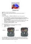
WPP001-ET:
WPP001-ETT :
Note: the PulsePen works with a computer, supplied by the user, in order to display and save signals. The
computer connection is galvanically isolated due to the radio link with the wRs1 unit. During patient
examination is moreover necessary to insert the systolic and diastolic pressure values measured with a
validated sphygmomanometer supplied by the user.
1
Tonometric Unit wTn1:
1.
2.
3.
On / Off button: keep pressed for about 1 sec.
Cap for battery replacement: pull away from the tonometer’s body. Extract the old battery
pushing it from the opposite side of the opening. Insert the new fresh battery never forcing and
following the specified polarity. Reinsert the cap in its final position pushing it until snap occurs.
Active part of the tonometric sensor.
ECG Unit wEc1:
1.
2.
3.
On / Off button: keep pressed for about 1 sec.
Cap for battery replacement: pull away from the unit’s body. Extract the old battery. Insert the
new fresh battery never forcing and following the specified polarity. Reinsert the cap in its final
position pushing it until snap occurs.
Patient cables connectors.
Signal Receiver Unit wRs1:
1.
Led signalling the operating mode. This Led blinks green when the software is not running or in
case the device is not correctly installed. This Led is fixed green during normal operations while
it’s red during reprogramming / update.
2
Intended use:
In this manual, when writing about device or equipment, the reference is to all its parts, unless otherwise noted.
Each unit alone does not produce useful results.
!
This device is intended to be exclusively used by medical / paramedical personnel. Pls keep in mind
that morphology and quality of the pressure signal acquired by not skilled people could give erroneous
signal interpretation.
The primary functions are capture, display and storage of the arterial tonometric signal in
order to later proceed to the calculation of the related parameters and of the Pulse Wave
Velocity - PWV, that defines the arterial stiffness. This instrument is based on the
applanation tonometry principle. According to this method, the sensor is placed over the
skin were the artery is found, applying a moderate pressure; in this way the artery comes
slightly compressed (applanation tonometry) with a balance of the circumferential forces
inside the vessel. In this way the sensor records the pressure in the middle of the
compressed artery. Intermediate layers between sensor and vessel, with their thickness
and rigidity, that change for each individual case, influence the pressure measured by the
sensor in a not, a priori, quantifiable manner. For this reason it is necessary to calibrate
tonometric signals using an external sphygmomanometer (supplied by the operator) in
order to assess the systolic and diastolic pressures. The calibration process is based on
the assumption that diastolic and mean pressures substantially don’t change along the
arterial tree.
Pe
Pe = Pi
Pi
The pulse wave velocity is defined as the propagation velocity of the pressure wave from the center to the
periphery and is therefore obtained by dividing the distance between two examined points (for example Carotid
and Femoral) by the related sphygmic wave transit time (DeltaT).
This propagation time can be assessed in two different ways:
A) By using the wEc1 unit in association with the wTn1 unit in order to measure the delay time between the
ECG-R wave and the “foot” of the tonometric wave, first in Carotid (R-cW) and after in the peripheral artery
under examination (for example the Femoral Artery according to the figure, R-fW ) and obtaining the difference,
DeltaT.
B) By using two wTn1 units to contemporary capture two tonometric signals, one of them in Carotid and the
other in the selected peripheral Artery, obtaining the time interval DeltaT between the two wave’s “feet”.
!
The ECG lead captured must only be used for PWV determination and never must be used for a
diagnosis on the patient!
3
Technical Specifications:
wTn1:
On / Off button
Resolution: 0.004 mmHg
Dynamic range: $ 220 mmHg
Capture : 16 bit @ 1000 S/sec
Data Rx / Tx: radio link, ISM 2.4 GHz
Acoustic signal: On/Off switching
Power supply: Alkaline AAA - 1.5V IEC LR03
battery
Max applicable sensor force: 5.5 Kg
Vibrations: # 20 g @ 0 ÷ 2 KHz sinusoidal
Shock: # 150 g
Weight: 25g without battery
Dimensions [mm]: 114 (L) x 25 (W) x 20 (H)
wRs1:
P.C. Connection : USB
Power supply: powered by P.C. connector
Led: operating mode signalling
Data Rx / Tx: radio link, ISM 2.4 GHz
Weight: 11g
Dimensions [mm]: 67 (L) x 25 (W) x 11 (H)
General:
Approximate autonomy: 50h
Ambient temperature: 5 ÷ 40 /C
Relative humidity: 30% ÷ 80% non condensing
Atmospheric pressure: 860 ÷ 1060 hPa
CV010:
Universal terminals for tab, clip, press-stud
electrodes.
Connectors DIN 42802 compliant
wEc1:
On / Off button
Resolution: 0.15 µV
Dynamic range: $ ± 4.5 mV
Capture : 16 bit @ 1000 S/sec
Data Rx / Tx: radio link, ISM 2.4 GHz
Acoustic signal: On/Off switching
Power supply: Alkaline AAA - 1.5V IEC LR03
battery
Vibrations: # 20 g @ 0 ÷ 2 KHz sinusoidal
Weight: 37g without battery
Dimensions [mm]: 49 (L) x 75 (W) x 21 (H)
Computer:
Processor clock frequency $ 2GHz
Ram memory $ 2 GB
Free Hard Disk space $200 MB
Graphical resolution $1280 x 800, 256 colours
Operating system: Windows® XP SP2..., Vista,
Windows® 7, Windows® 8 - 32/64 bit
Free USB ports: 1
IEC 60950-1 compliant
Classification:
Class IIa medical device according to the Directive 93/42/CE
Computer Connection:
Connection of the WPP001-ET / WPP001-ETT device to the computer occurs through the wRS1 unit by
inserting it in one USB port:
Software Installation:
Insert the included Usb memory drive in the computer port.
•
•
•
•
Pls wait the end of the following procedure before inserting the wRS1 unit in one Usb port!
Launch Setup.exe : the WPulsePen_LP SW will be installed creating a desktop icon together with the
wRS1 Usb drivers.
Upon finishing installation, insert the wRS1 unit in the Usb port and wait for the correct device
identification. In case of problems, manually reinstall the drivers that are in the following folder: wRs
Usb Driver
Run the software WPulsePen_LP. The associated software release is WPP001LP-ETT- 1.1.0.
4
Use of the device:
Insert the wRS1 receiver in one Usb port and wait for device recognition. Extract the cap from the wEc1 and
wTn1 units, insert batteries into the battery compartment strictly following the indicated polarity (see pg 2) and
reinsert the cap.
! Use only 1.5V IEC LR03 – AAA Alkaline batteries.
Note: dead batteries must be disposed of in the special containers, since they are high-pollution wastes !
Using fresh disposable ECG electrodes Ag/AgCl with incorporated
gel, to be used for crocodile clips, position them as follows:
R (red): subclavian right region
B (black): subcostal left region
The suggested position can be modified according to the operator
opinion when altered ECG signals are present, for example in case
of pathologies. Direct electrodes contact with synthetic dresses
must be avoided because it’s cause of superimposed noise; in this
case it’s useful to interpose one sheet of paper.
Connect patient cable crocodiles to related electrodes according to
their type (type A or type B, see figure at side) and insert
connectors from the other side in the corresponding wEc1 sockets.
A
B
Start the Software WPulsePen_LP on the Computer.
Switch on the wEc1 / wTn1 unit by keeping pressed the on/off key until the acoustic signalling (about 1 sec).
Such signal ends with a single “beep” in case of wEc1 or wTn1 programmed as Sensor1 (red trace) while ends
with two “beeps” in case of wTn1 programmed as Sensor2 (blue trace).
1.
2.
3.
4.
5.
6.
7.
8.
9.
10.
11.
12.
Key for the patient selection in order to start a new examination
Key to archive access.
Setup key and device programming.
On line Help Key.
Indicator of correct data exchange with the wRs1 receiver (green).
Indicator of wRs1 Usb device recognized (green).
Graphical battery gauge
Numeric battery gauge: in case of less then 10% indication, the battery must be replaced.
Icon for Ecg or Tonometric active sensor.
Bar that shows data from Usb adapter waiting for processing: shorter it means higher computer speed.
The positive battery terminal becomes yellow during standby, i.e. when “Freeze” is active or during
screens different from signals capture.
Sensor 1 corresponds to the red signal (Ecg or Tonometer) while sensor 2 corresponds to the blue signal
(only Tonometer).
5
Select the Patient icon and insert information as name, surname, birth date, gender: at this point the keys
corresponding to the Arteries will be enabled. Choosing one of them a new window will be opened. Place the
PulsePen probe on the region of interest: captured signals will be displayed on the computer screen. An
automatic freeze function, stops the signal capture in case of no activity on Sensor 2 (blue trace).
In order to obtain good quality tonometric signals, the patient must be lying down on
the bed while the operator’s elbow must firmly lye on a surface and the probe’s
handle is near the sensor in such a way that operator’s fingers touch the patient’s
skin, reducing in this way tremors (see figure). The probe must be kept
perpendicular and not tilted.
Once a good quality signal has been captured of the required duration, the hard disk
storage is enabled by pressing the icon with the diskette symbol (or the Enter key): a
new window will be displayed in order to insert systolic and diastolic pressures
captured by an external sphygmomanometer. In case of peripheral artery, also
distance values are required, measured in millimetres: they are three and are related
to Carotid-Peripheral Artery, Carotid - Suprasternal Notch and Suprasternal Notch Peripheral Artery: in this way during the PWV assessment it’s possible to apply both
methods for the distance evaluation, i.e the direct method (direct distance multiplied
by 0.8) and the subtractive one.
The WPulsePen_LP software storage is in text format file (*.txt) in the subfolder “ASCII” of the
WPulsePen_Data folder. The initial part of the file contains patient data, the explored artery (Car Carotid, Fem
Femoral, ...), examination’s date/hour, systolic and diastolic pressure values and distances between capture
points manually inserted by the operator and after that, two columns with signal samples of the two sensors (Ecg
+ Tonometer or two Tonometers).
Selecting the Archive icon, all the examinations are shown and it’s possible to choose which one to display on
the screen.
The Setup icon allows to select language, date format, ..., while the Help icon opens a window with the on line
instructions (pls refer to this online help for updated operating instructions).
In order to switch off the sensors, keep pressed the on/off key until the acoustic signalling (about 1 sec).
Activation of wEc1 and wTn1 units is shown on the computer screen (points 7, 8, 9, 11, 12) of the previous
image, as the battery level and the active/standby state. Closing the program, automatically switches off the
wEc1 e wTn1 units: it also occurs in case of no connection with the wRs1 units for more than 30 sec. The last
situation takes place also when the software WPP001LP-ETT is not executing: wEc1 e wTn1 units wait for
connection with the wRs1 unit without transmitting data.
6
Maintenance and cleaning:
No particular periodic maintenance or calibration operations are necessary on the instrument.
!
In the case of prolonged non-use, remove the batteries.
Before use, the metallic disc of the PulsePen probe, the patient cable and the probe’s case must be cleaned,
using a clean, dry cloth or dampened with a small quantity of alcohol. Pay attention especially to the probe’s
plunger avoiding mechanical stresses.
!
Note: be very careful to keep the alcohol or other liquids from penetrating into the PulsePen
probe or into the other units because this could cause serious problems, irreparably damaging internal
parts !
!
The PulsePen Ecg cables are very thin and flexible in order to be easy to handle. One must avoid
pulling, and bending them at a right angle so as not to damage them.
!
•
•
•
•
•
•
•
•
•
•
•
•
•
•
•
•
•
•
Warnings and precautions for use:
This instrument is intended to be used only by medical/paramedical personnel in medical
ambulatory.
Do not use in the operating room, or in any case where there are inflammable gases/substances.
Do not use for intra cardiac applications or at direct contact with internal body parts.
Data elaboration must be performed by the doctor through dedicated software.
Do not sterilize either in autoclave neither with liquid substances.
Do not submit the pressure plunger of the tonometric unit wTn1 to mechanical shocks as impacts or
falls.
Regularly clean the disc of the tonometric probe wTn1, the terminals of the patient cable CV010
and the case after each use, as indicated in the previous paragraph.
Keep the wTn1 and wEc1 units with the related patient cable at a distance of no less than 1.5
meters from the computer and the same computer at no less than 1.5 meters from the patient.
Avoid touching simultaneously any part of the computer included the wRs1 unit and one or both the
wEc1 unit, included the patient cable, and wTn1.
Do not immerse any part of the device into water or other substances, or expose it to sprays. Never
use Gel on the pressure sensor of wTn1!
Do not carry out any maintenance work on the device opening it; in the case of malfunctioning of
the device, contact DiaTecne s.r.l.
If any abrasions, sheath tears, or any kind of defects appear in the patient cable CV010,
immediately suspend use of the device and send the defective part to Diatecne s.r.l. for
repair/replacement.
Do not use the device in case of breakage of the case, do not try to repair it but contact Diatecne
s.r.l. for repair/replacement.
Do not make changes of any kind to the device.
Keep the tonometric probe wTn1 and patient cable terminals away from electrical outlets and
surfaces where there may be potentially dangerous voltages.
Use a battery-powered (portable) computer or, alternatively, an AC-powered computer, medical
regulations in force compliant.
Use the device at a safe distance from sources of electromagnetic disturbance such as cordless
telephones operating at radio frequency/cellular phones, Bluetooth devices and WiFi or other
equipment emitting high frequency electromagnetic waves.
During examination keep the wEc1 unit at a distance at least of 20 cm from the patient and
operator and limit the duration of contact of the wTn1 unit with patient and operator for the time
required for the examination: this is in order to reduce the exposure time to the electromagnetic
radiations due to radio signal transmission.
7
•
•
•
•
•
•
•
•
•
Use only 1.5V batteries of the indicated type, inserting them as stated and checking their condition
before each use (dead or damaged batteries may cause leakage of acid).
Do not switch on or use the device if the cover of the battery compartment is not correctly closed.
Insert the patient cable CV010 connectors only into the corresponding sockets of the wEc1 unit. Do
not connect those plugs in any other way.
The equipment must never be used in situations where a defibrillator is required, since it has not
been designed for such use.
During Carotid pressure signals recording the compression of the Carotid bulbs may accidentally
produce reduction of heart rate. This kind of phenomenon could be more pronounced in old aged
patients with accentuate vagal sensitivity. It is highly recommended to stop the examination upon
appearance of bradycardia. We furthermore remember that is absolutely to avoid simultaneous
compression of Carotid bulbs, considering that this can cause syncope by arterial hypotension and
severe bradyarrhythmias.
Install an antivirus software on the computer used for the capture of the signals coming from the
device.
Reduce the probability of radio interference following prescription of the next paragraph.
Use the equipment only for the purposes stated in this manual.
DiaTecne s.r.l. will not be held responsible for any damages caused to persons, animals, or things
if the user does not scrupulously follows the indications given in this manual.
Reciprocal interferences with other equipments:
The PulsePen device was designed to be immune to electrical, electromagnetic, electrostatic and magnetic
disturbances that are normally present; likewise, the PulsePen produces a small amount of disturbances for
other equipments. It cannot, however, be excluded that, in particular situations, some functioning anomalies
could appear also in the form of signal alteration; in this case it is necessary, when possible, to move away all
potential sources of disturbance, or to move to a more appropriate location.
Considering the intended use of the device that requires a medical qualified operator, he/she may easily
recognize any anomalous functioning situation, such as, for example, the presence of “noise” superimposed to
the signal or alteration of the morphology, and follow the indications suggested here.
Typical noise sources are the “hotspot”/WiFi devices, Bluetooth devices / Zigbee devices and any kind of
transmitter in the 2,4 GHz frequency band.
! Ensure that the WiFi / Bluetooth functions of the computer and cellular phones, are switched off
during the use of the apparatus. When available, activate the ‘aero mode’ on this devices.
•
•
•
•
•
•
Medical devices require special cautions for electromagnetic disturbances (EMC) and must be
installed according to instructions in the following tables 1 ÷ 4.
Mobile devices for radio frequency communications may disturb electromedical devices.
For the correct use of the PulsePen device, the wEc1 and wTn1 units must be in a 3 meters radius
from the wRs1 unit. Higher distances could influence the correct operation.
The use of cables and accessories different from those in the original package could adversely influence
the performances of the device.
Respect distances from other devices according to table 4.
The PulsePen device transmits radiofrequency in the ISM 2.4 GHz band with MSK modulation,
ERP = 2 dBm.
8
Table 1: Electromagnetic emissions :
The PulsePen is suitable for use in the specified electromagnetic environment. The purchaser or user of the
PulsePen should assure that it is used in an electromagnetic environment as described below
Emissions tests
Compliance
Electromagnetic Environment
RF emissions
CISPR 11
Group 1
The PulsePen uses RF energy only for its internal function.
Therefore, the RF emission is very low and not likely to cause
any interference in nearby electronic equipment.
RF emissions
CISPR 11
Class B
The PulsePen is suitable for use in all establishments,
including domestic establishments and those directly connected
to the public low-voltage power supply network that supplies
buildings used for domestic purposes.
Harmonic emissions
IEC 61000-3-2
Not
applicable
Voltage fluctuations/
Flicker emissions
IEC 61000-3-3
Not
applicable
Table 2: Electromagnetic immunity :
The PulsePen is suitable for use in the specified electromagnetic environment. The purchaser or user of the
PulsePen should assure that it is used in an electromagnetic environment as described below:
Immunity
Test
IEC 60601-1-2
Test level
Compliance
level
Electromagnetic Environment
±6 KV contact
Electrostatic
discharge (ESD)
IEC 61000-4-2
±8 KV air
IEC 60601-1-2 Floors should be wood, concrete or ceramic
Test level
tile. If floors are covered with synthetic
material, the relative humidity should be at
least 30%.
Electrical Fast ±2 KV for power
Transient/Burst supply lines
IEC 61000-4-4
±1 KV for
input/output lines > 3
m
Not applicable
Mains power quality should be that of a
typical commercial or hospital environment.
Surge
IEC 61000-4-5
Not applicable
Mains power quality should be that of a
typical commercial or hospital environment.
±1 KV differential
mode
±2 KV common mode
9
Voltage dips,
short
Interruptions
and Voltage
variations on
power supply
input lines
IEC 61000-4-11
0% Un for 0.5 cycles
Not applicable
40% Un for 5 cycles
70% Un for 25 cycles
0% Un for 5 s
Power frequency 3 A/m
(50/60 Hz)
Magnetic Field
IEC 61000-4-8
Mains power quality should be that of a
typical commercial or hospital environment.
If the user of the PulsePen requires
continued operation during power mains
interruptions, it is recommended that the
computer used with the PulsePen be
powered from an uninterruptible power
supply or a battery.
IEC 60601-1-2 Power frequency magnetic fields should be
Test level
at levels characteristic of a typical location
in a typical commercial or hospital
environment.
Table 3: Electromagnetic immunity :
The PulsePen is suitable for use in the specified electromagnetic environment. The purchaser or user of the
PulsePen should assure that it is used in an electromagnetic environment as described below:
Immunity Test
IEC 60601-1-2
Test level
Compliance
level
Electromagnetic Environment
Portable and mobile RF communications
equipment should be used no closer to any
part of the PulsePen, including cables,
than the recommended separation distance
calculated from the equation applicable to
the frequency of the transmitter.
Recommended separation distance:
Radiated RF
IEC 61000-4-3
3V/m
80 MHz ÷ 2.5 GHz
3V/m
Conducted RF
IEC 61000-4-6
3V/m
150 KHz ÷ 80 MHz
Not applicable
d = 1.2 %P 80 MHz ÷ 800 MHz
d = 2.3 %P 800 MHz ÷ 2.5 GHz
d = 1.2 %P
Where P is the maximum output rating of the transmitter in watts (W) according to the transmitter
manufacturer and d is the recommended separation distance in meters (m).
Field strengths for fixed RF transmitter, as determined by an electromagnetic site survey, should be less
then the compliance level in each frequency range.
Interference may occur in the vicinity of equipment marked with the following symbol:
10
Table 4: Recommended separation distances between portable and mobile RF communications equipment
and the PulsePen:
The PulsePen is intended for use in an electromagnetic environment in which radiated RF disturbances are
controlled. The customer or the user of the PulsePen can help prevent electromagnetic interference by
maintaining a minimum distance between portable and mobile RF communications equipment (transmitter) and
the PulsePen as recommended below, according to the maximum output power of the communications
equipment.
Rated maximum
output power of the
transmitter
(W)
Separation distance according to frequency of transmitter
(m)
150 KHz ÷ 80 MHz
80 MHz ÷ 800 MHz
800 MHz ÷ 2.5 GHz
d = 1.2 %P
d = 1.2 %P
d = 2.3 %P
0.01
0.12
0.12
0.23
0.1
0.38
0.38
0.73
1
1.2
1.2
2.3
10
3.8
3.8
7.3
100
12
12
23
For transmitters rated at the maximum output power not listed above, the recommended separation distance d in
meters (m) can be estimated from the equation applicable to the frequency of the transmitter, where P is the
maximum output power rating of the transmitter in watts (W) according to the transmitter manufacturer.
Notes:
-
at 80MHz and 800MHz, the separation distance for the higher frequency range applies
-
These guidelines may not apply in all situations. Electromagnetic propagation is affected by absorption
and reflection from structures, objects and people
11
Problems in use and solutions:
THE DEVICE DOES NOT TURN ON ( NO ACOUSTIC SIGNALING):
•
Check to see that the battery is of the required type, that is inserted in the right way and that it’s not dead.
•
Keep the On/Off button pressed until the acoustic signaling (about 1 sec).
•
Remove and reinsert the battery.
NO SIGNALS ARRIVE TO THE COMPUTER:
•
Check to see that the wEc1 and wTn1 units are turned on and that software icons related to the wRs1 unit
are both green: in case they are not, close the software, extract and reinsert the wRs1 signal receiver, restart
the software. In case the problem remains, the Usb drivers reinstallation is suggested.
•
Ensure that the Computer Protection software, such as Antivirus, Firewall, etc., does not prevent access to
external Usb devices.
•
Make sure that the system is not in “Freeze” mode due to absence of tonometric signal on the PulsePen
probe. Touch the sensor with fingers.
•
Check to see that the radio channel of wRs1, wEc1, wTn1 units is the same. Pls refer to the on line help for
more details.
If you find it’s not possible to solve the listed problems by yourself, or if you have doubts regarding the functioning
of the equipment, please contact DiaTecne s.r.l. by e-mail at [email protected].
You will receive technical assistance in a short time.
Notes on recycling:
DiaTecne is sensitive to environmental issues linked to the production of waste.
The user that wishes to dispose of the apparatus at its life end, should contact DiaTecne s.r.l. and will receive
appropriate instructions.
Adequate waste selection before recycling and eco-compatible waste processing contributes to avoiding detrimental
effects on nature and on human health, an promotes the reuse and recycling of the material of which the product is
made.
Please note that inadequate disposal of the product entails the application of the normative sanctions of the country
where this should take place.
12
Symbols and Abbreviations:
Manufacturer information
This symbols states that reading the user manual before using the apparatus is mandatory
Warning: pay attention
Class II device
This symbol advices that applied parts are of BF type
The device incorporates radio transmitters (not ionizing radiations)
The crossed garbage can symbol indicates that, when no longer functional, the product should be disposed
of separately from other waste as electronic waste.
SN: the serial number is on each unit in the format”yyppp“: first two digits are for production year, remaining digits
are for progressive counting (hexadecimal code).
13
Index
pag.
Composition . . . . . . . . . . . . . . . . . . . . . . . . . . . . . . . . . . . . . . . . . . . . . . . . . . . . . . . . . . . . . . . . . . . . . . . . . 1
Tonometric Unit wTn1 . . . . . . . . . . . . . . . . . . . . . . . . . . . . . . . . . . . . . . . . . . . . . . . . . . . . . . . . . . . . . . . . . 2
ECG Unit wEc1 . . . . . . . . . . . . . . . . . . . . . . . . . . . . . . . . . . . . . . . . . . . . . . . . . . . . . . . . . . . . . . . . . . . . . . 2
Signal Receiver Unit wRs1 . . . . . . . . . . . . . . . . . . . . . . . . . . . . . . . . . . . . . . . . . . . . . . . . . . . . . . . . . . . . . . 2
Intended use . . . . . . . . . . . . . . . . . . . . . . . . . . . . . . . . . . . . . . . . . . . . . . . . . . . . . . . . . . . . . . . . . . . . . . . . . 3
Technical Specifications . . . . . . . . . . . . . . . . . . . . . . . . . . . . . . . . . . . . . . . . . . . . . . . . . . . . . . . . . . . . . . . . 4
Classification . . . . . . . . . . . . . . . . . . . . . . . . . . . . . . . . . . . . . . . . . . . . . . . . . . . . . . . . . . . . . . . . . . . . . . . . 4
Computer Connection . . . . . . . . . . . . . . . . . . . . . . . . . . . . . . . . . . . . . . . . . . . . . . . . . . . . . . . . . . . . . . . . . . 4
Software Installation . . . . . . . . . . . . . . . . . . . . . . . . . . . . . . . . . . . . . . . . . . . . . . . . . . . . . . . . . . . . . . . . . . . 4
Use of the device . . . . . . . . . . . . . . . . . . . . . . . . . . . . . . . . . . . . . . . . . . . . . . . . . . . . . . . . . . . . . . . . . . . . . 5
Maintenance and cleaning: . . . . . . . . . . . . . . . . . . . . . . . . . . . . . . . . . . . . . . . . . . . . . . . . . . . . . . . . . . . . . . 7
Warnings and precautions for use . . . . . . . . . . . . . . . . . . . . . . . . . . . . . . . . . . . . . . . . . . . . . . . . . . . . . . . . . 7
Reciprocal interferences with other equipments . . . . . . . . . . . . . . . . . . . . . . . . . . . . . . . . . . . . . . . . . . . . . . 8
Problems in use and solutions . . . . . . . . . . . . . . . . . . . . . . . . . . . . . . . . . . . . . . . . . . . . . . . . . . . . . . . . . . . . 12
Notes on recycling . . . . . . . . . . . . . . . . . . . . . . . . . . . . . . . . . . . . . . . . . . . . . . . . . . . . . . . . . . . . . . . . . . . . 12
Symbols and Abbreviations . . . . . . . . . . . . . . . . . . . . . . . . . . . . . . . . . . . . . . . . . . . . . . . . . . . . . . . . . . . . . 13
Document printing:
In case more printed copies of the document are necessary, open the corresponding “pdf” file with the Adobe Reader
program or similar, select options “booklet”, “both sides”, “left binding ”, “page size A4", print, fold and bind as
shown:
Note: with a view to constant product improvement, Diatecne s.r.l. reserves the right to make any changes it deems
necessary, without notice, both to this manual and to the PulsePen device, communicating these changes only to
the competent bodies!
14
15
PulsePen® is a trademark of DiaTecne s.r.l. - Italy
Copyright © 2015 - V. 4.3 Eng / Oct 2015