1
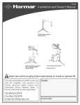
Accessory
INSTALLATION
INSTRUCTIONS
GRIP HEATER
P/N 08T72-MGH-N10
PARTS LIST
Application
Publication No.
VFR1200X/XD
Issue Date
MII
January 2014
TORQUE CHART
Refer to the Service Manual for the torque values of the
removed parts.
(10)
INSTALLATION
(2)
(3)
CAUTION
•• To prevent burns, allow the engine, exhaust system,
radiator, etc., to cool before installing the accessory.
•• Be sure to obser ve all safety messages and
precautions described in the Service Manual while
removing and installing the fuel tank.
NOTE:
•• This manual is focusing on VFR1200XD, but perform
this work for other types. If there are any differences,
each difference will describe in this manual.
•• When working with lifting the fuel tank, always
p e r f o r m t h i s w o r k w i t h t w o p e r s o n s; i t i s
recommended that one person lifts the tank.
•• Disconnect the throttle cable from the right grip as
instructed in the motorcycle’s Service Manual.
•• For secure adhesion of the grip heaters use the
recommended adhesive agent (Honda Bond A) or
equivalent.
•• Be sure to open and close the throttle to check for
smooth operation after installation of the right grip
heater.
•• Disconnect the negative (-) cable from the battery
before installing this accessory.
•• The memories of the clock will be erased when you
disconnect the battery. Reset the memories after
reconnecting the battery.
•• Reinstall the removed parts on the motorcycle and
make sure that the wires and harnesses are not
pinched.
•• Trim the excess ends off the wire ties after attaching
them to the wire harnesses. Do not allow the cut part
of the wire tie to interfere with another harness or
brake hose.
•• After handle grip heater installation, check the lights
(e.g. right / left turn signal lights and brake lights) for
proper operation.
(1)
(4)
(8)
(9)
(5)
No.
(6)
(7)
Description
Qty
(((
Right grip heater
1
(((
Left grip heater
1
(((
Heater controller
1
(((
Suspension (Not used.)
1
(((
Clip band (Not used.)
6
(((
Wire tie (narrow/short) (Not used.)
6
(((
Wire tie (narrow/long)
6
(((
Wire tie (wide/short)
6
(((
Wire tie (wide/long) (Not used.)
3
URL paper
1
((((
TOOL AND SUPPLIES REQUIRED
Flat-tip screwdriver
Nippers
Marker
Scale
Electrical tape
Honda Bond A
Thread lock
Grease
Isopropyl alcohol
Shop towel
© 2014 Honda Motor Co., Ltd. - All Rights Reserved.
1 of 16
87951-MGH-N102
1.
Remove the seat, and disconnect the negative (-)
cable from the battery.
3.
Remove the clips as shown.
<Left side>
SEAT
LEFT
MIDDLE
COWL
CLIP
4.
LEFT FRONT FORK
Remove the screws as shown.
<Left side>
SCREW
2.
Remove the clips as shown.
<Left side>
LEFT MIDDLE
COWL
LEFT MIDDLE COWL
CLIP
SCREW
CLIP
2 of 16
5.
Remove the left middle cowl as shown.
•• Make sure that the 2-pin waterproof connector
is disconnected before removing the left
middle cowl.
6.
Remove the left shroud cover and the left knee cowl
as shown.
2-PIN WATERPROOF
CONNECTOR (Blue)
LEFT KNEE COWL
COLLAR
BOLT
LEFT MIDDLE COWL
Disconnect the connector.
7.
8.
Motorcycle with Front fog attachment
•• Make sure that the 4-pin connector is disconnected
before removing the left middle cowl.
Repeat on the right side.
Remove the wire tie and dummy connectors.
Remove the dummy connectors.
4-PIN WATERPROOF
CONNECTOR (Black)
4-PIN WATERPROOF
DUMMY CONNECTOR
(Black) (Save)
HARNESS BOOT
2-PIN WATERPROOF
CONNECTOR (Black)
HARNESS BOOT
FOG LAMP SWITCH
HARNESS
2-PIN WATERPROOF
DUMMY CONNECTOR
(Black) (Save)
4-PIN CONNECTOR (Black)
Disconnect.
HARNESS BOOT
MOTORCYCLE’S
WIRE TIE
Remove.
3 of 16
9.
Remove the knuckle guard from the motorcycle’s left
grip as shown.
13. Using a isopropyl alcohol, remove all traces of
adhesive from the left handlebar pipe.
<Left side>
RUBBER WASHER
ISOPROPYL ALCOHOL
LEFT HANDLEBAR PIPE
BOLT
WASHER
BOLT
14. Mark the left grip heater harness in the position
shown.
LEFT KNUCKLE GUARD
10. Remove the handlebar weight from the motorcycle’s
left grip as shown.
LEFT GRIP
HEATER
MARKER
LEFT GRIP HEATER
HARNESS
49
70
HANDLEBAR
WEIGHT
LEFT GRIP
11. Repeat on the right side.
12. Remove the left grip as shown.
LEFT GRIP (Save)
ISOPROPYL ALCOHOL
4 of 16
0m
0m
m
m
15. Apply the Honda bond A to the left handlebar as
shown.
•• Apply evenly to the whole circumferential
surface of the left handlebar.
•• Pe r form t h e n ex t ste p 5 minute s af te r
application.
17. Slide the left grip heater onto the left handlebar as
indicated.
•• Use an assistant to steady the motorcycle
while installing the grips.
•• Wipe up excess adhesive at once.
NOTICE
•• Do not tap on the grip end with a hammer and do
not twist the grip to install the grip heater onto the
handlebar, as it can damage the element.
Honda BOND A
•• Avoid putting pressure on the switch part when
inserting the left grip heater. There is a possibility
that the switch part will break. Also, install so that
there is no gap with the switch holder.
0
10
mm
LEFT HANDLEBAR
•• If the grip gets stuck halfway during installation,
apply isopropyl alcohol to the gap between the grip
heater. Do not try to remove the grip heater using
force or a screwdriver, etc. Damage to the grip
heater wire can result.
•• Do not touch the left handlebar and turn on the
heater switch at least one hour after attachment.
16. Spray isopropyl alcohol over the inside of the grip
heater and outside of the left handlebar.
ISOPROPYL ALCOHOL
LEFT GRIP HEATER
LEFT HANDLEBAR
SWITCH HOLDER
LEFT GRIP HEATER
Insert until there is contact with the switch holder, then align with the indicated position.
<VFR1200XD>
<VFR1200X>
LEFT GRIP HEATER
LEFT GRIP HEATER
7 mm
Align.
5 of 16
20. Raise the fuel tank as shown.
18. Remove the upper cowl stay as shown.
•• Perform this work with two persons, where
one supports the upper cowl, then the other
one removes the upper cowl stay.
SCREW
COLLAR
FUEL TANK
Lift up.
BOLT
Repeat on the right side.
CLAMP
BREATHER TUBE
Release.
COLLAR
UPPER
COWL
BOLT
UPPER COWL STAY
DRAIN TUBE
Release.
19. Remove the left inner panel as shown.
•• Repeat on the right side.
21. Remove the connector from the ECU as shown.
LEFT INNER PANEL
4-PIN WATERPROOF
CONNECTOR (Black)
2-PIN CONNECTOR (Brown)
6 of 16
ECU
22. Pull out the ECU as shown.
24. Route the left grip heater harness as shown.
ECU
LEFT GRIP HEATER HARNESS
23. Route the left grip heater harness as shown.
<Left side>
LEFT GRIP
HEATER HARNESS
LEFT GRIP
HEATER HARNESS
<VFR1200X>
25. Pass the left grip heater harness as shown.
LEFT GRIP
HEATER HARNESS
LEFT GRIP
HEATER HARNESS
7 of 16
26. Connect the left grip heater harness as shown.
28. Remove the right grip as shown.
NOTE
Disconnect the throttle cable from the right grip as
instructed in the motorcycle’s Service Manual. Do not
try to disconnect the cable with force using the pliers,
etc. Refer to the motorcycle’s Service Manual.
4-PIN WATERPROOF
CONNECTOR (Black)
LEFT GRIP
HEATER HARNESS
2-PIN WATERPROOF
CONNECTOR (Black)
THROTTLE CABLE
27. Remove the screws from the motorcycle as shown.
<Right side>
RIGHT HANDLE
SWITCH HOLDER
RIGHT HANDLE
SWITCH HOLDER
RIGHT GRIP (Save)
29. Mark the right grip heater harness in the position
shown.
SCREW
m
12
5
m
m
5
48
71
5
m
m
m
RIGHT GRIP HEATER
MARKER
RIGHT GRIP
HEATER HARNESS
8 of 16
30. Wind the electrical tape on the marked position as
shown.
32. Apply grease to the
parts of the throttle cables
and inner grip as shown.
RIGHT GRIP HEATER
GREASE
RIGHT GRIP
HEATER HARNESS
GREASE
MARK
(125 mm)
ELECTRICAL TAPE
THROTTLE CABLE
RIGHT GRIP
HEATER HARNESS
RIGHT GRIP HEATER
20 mm
INNER GRIP
MARK
(125 mm)
33. Install the right grip heater and right switch holder in
the reverse order of removal.
•• After installation, refer to the Service Manual
and adjust the throttle freeplay.
ELECTRICAL TAPE
Wind up 2 - 3 laps
centering on the mark.
31. Mark the right grip heater harness in the position
shown.
RIGHT GRIP HEATER
ELECTRICAL TAPE
RIGHT GRIP
HEATER HARNESS
RIGHT GRIP HEATER
RIGHT GRIP
HEATER HARNESS
ELECTRICAL TAPE
MARKER
Mark the center of
the electrical tape.
9 of 16
34. Twist the throttle grip as shown.
•• Check for smooth opening of the throttle and
that it automatically snaps closed from any
opening, in all steering positions.
36. Route the right grip heater harness as shown.
RIGHT GRIP HEATER HARNESS
RIGHT GRIP HEATER
35. Route the right grip heater harness as shown.
RIGHT GRIP
HEATER
RIGHT GRIP
HEATER HARNESS
RIGHT GRIP
HEATER HARNESS
THROTTLE
CABLE
37. Route the right grip heater harness as shown.
AIR CLEANER
RIGHT GRIP
HEATER HARNESS
10 of 16
38. Route the right grip heater harness as shown.
40. Remove the dummy connector as shown.
AIR CLEANER
2-PIN WATERPROOF
CONNECTOR (Black)
2-PIN WATERPROOF
DUMMY CONNECTOR
(Black) (Save)
Remove the connector from the clip band.
RIGHT GRIP
HEATER HARNESS
CLIP BAND
39. Turn up the rubber as shown.
AIR CLEANER
2-PIN WATERPROOF
CONNECTOR (Black)
Remove from the clip band.
41. Route the right grip heater harness as shown.
RUBBER
Turn up.
RIGHT GRIP
HEATER HARNESS
11 of 16
42. Connect the right grip heater harness as shown.
43. Remove the wire tie and dummy connector.
<Right side>
Remove the dummy connector.
10-PIN WATERPROOF
CONNECTOR (Black)
HARNESS BOOT
10-PIN WATERPROOF
DUMMY CONNECTOR
(Black) (Save)
2-PIN WATERPROOF
CONNECTOR (Black)
MOTORCYCLE’S
WIRE TIE
Remove.
RIGHT GRIP
HEATER
HARNESS
Secure the right grip heater harness to the clip band.
CLIP BAND
2-PIN WATERPROOF
CONNECTOR (Black)
After connecting,
secure to the clip band.
RIGHT GRIP
HEATER HARNESS
12 of 16
HARNESS BOOT
44. Connect the heater controller as shown.
10-PIN WATERPROOF
CONNECTOR (Black)
HEATER CONTROLLER
After connecting, store the heater
controller in the harness boot.
45. Secure the right and left grip heater harness using
the wire ties as shown.
<Front side>
WIRE TIE (wide/short)
Secure the mark on the right and left grip
heater harness to the motorcycle’s harness.
MARK
(490 mm)
MARK
(485 mm)
RIGHT GRIP
HEATER HARNESS
LEFT GRIP
HEATER HARNESS
Secure the harness boot.
MOTORCYCLE’S
WIRE TIE (Reuse)
HARNESS BOOT
46. Secure the left grip heater harness using a wire tie
as shown.
<Left side>
WIRE TIE (Reuse)
Secure the motorcycle’s
harness and left grip heater
harness to the handle pipe.
LEFT GRIP
HEATER HARNESS
13 of 16
47. Secure the left grip heater harness using a wire tie
as shown.
49. Secure the harness boot as shown.
MOTORCYCLE’S WIRE TIE (Reuse)
Secure the harness boot to the cowl stay.
PARTING LINE
Do not let the
left grip heater
harness interfere.
WIRE TIE (narrow/long)
Secure the left grip heater
harness to the motorcycle’s
harness.
LEFT GRIP
HEATER HARNESS
HARNESS
BOOT
LEFT GRIP
HEATER HARNESS
Bundle the extra harness and store it in the harness boot.
48. Secure the left grip heater harness using a wire tie
as shown.
WIRE TIE (narrow/long)
Bundle the excess left
grip heater harness.
LEFT GRIP
HEATER HARNESS
HARNESS BOOT
WIRE TIE (wide/short)
Secure the mark on the left
grip heater harness to the
motorcycle’s harness.
MARK
(700 mm)
LEFT GRIP
HEATER HARNESS
50. Secure the right grip heater harness using a wire tie
as shown.
•• Open and close the throttle and confirm that
there is no tightness of the grip heater harness.
<Right side>
5 mm
MARK
TAPED PART
WIRE TIE (narrow/long)
Secure the mark on the taped part of
the right grip heater harness and the
motorcycle’s harness.
14 of 16
RIGHT GRIP
HEATER
HARNESS
51. Secure the right grip heater harness using a wire tie
as shown.
53. Secure the right grip heater harness using a wire tie
as shown.
<Right side>
AIR
CLEANER
WIRE TIE (narrow/long)
Bundle the excess right
grip heater harness,
and secure it to the
motorcycle’s harness.
WIRE TIE (Reuse)
Secure the motorcycle’s
harness and right grip heater
harness to the handle pipe.
RIGHT GRIP
HEATER HARNESS
52. Secure the right grip heater harness using a wire tie
as shown.
•• Move the handlebar right and left and check
that the harnesses are not pinched by the
neighboring and that they are not pulled taut.
<Right side>
WIRE TIE (wide/short)
Secure the mark
on the right grip
heater harness to the
motorcycle’s harness.
RIGHT GRIP
HEATER HARNESS
54. Install the rubber and fuel tank in the reverse order
of removal.
55. Reinstall the knuckle guard as shown.
•• Clean up with isopropyl alcohol before
applying thread lock.
•• Be sure to apply to the threads of the bolt.
•• Repeat on the right side.
MARK
(715 mm)
HANDLEBAR
WEIGHT (Reuse)
RUBBER
WASHER
(Reuse)
BOLT
(Reuse)
RIGHT GRIP
HEATER HARNESS
BOLT (Reuse)
WASHER
(Reuse)
LEFT KNUCKLE GUARD (Reuse)
THREAD LOCK
3~4 mm
5~6 mm
15 of 16
THREAD LOCK AREA
BOLT (Reuse)
56. Check the throttle cables not to interfere with the
knuckle guard as shown.
THROTTLE
CABLE
KNUCKLE GUARD
57. Install the motorcycle’s parts in the reverse order of
removal.
•• Confirm that the harness is not caught or too
tight.
58. Check the grip heater, throttle, headlight and the
other lights for proper operation.
•• Perform the operation check at least one hour
after attaching the left grip heater. Do not set
the heater level at more than 3.
•• Make sure to turn off the heater switch after
the operation check.
Please Convey The Following Information
To The Customer Before Delivery.
•• Please set the heater level at less than 2 one
week after attachment.
16 of 16