1
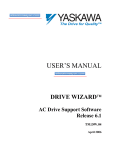
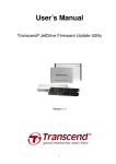
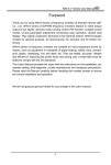
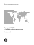
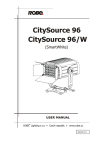
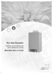
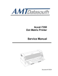
WRC Modbus to DeviceNet Gateway
for GPD 506/P5
Introduction
This document describes the recommended method to configure and connect Western Reserve Controls (WRC)
Modbus to DeviceNet gateway for use with the GPD 506/P5.
There currently are three types of gateways available:
• 1782-JDM-1 for RS232,
• 1782-JDM-2 for RS485
• 1782-JDM-3 for isolated RS232.
Although this document focuses on the use of this gateway with the GPD 506/P5 drive, it can be
used with any Yaskawa drive that communicates via Modbus.
Configuration & settings.
This procedure assumes that the reader is familiar with the GPD 506/P5 drive, DeviceNet, Modbus communication
protocol and PLC programming.
The configuration of the gateway is straightforward and must be done through configuration software such as
DeviceNet Manager, RSNetworx for DeviceNet, or equivalent. Figure 1 shows the configuration screen for
RSNetworx with the recommended parameter settings.
Figure 1. Basic Gateway Settings.
Yaskawa Electric America, inc-www.drives.com
02Y00025-0537 Page 1 of 12
Date: 10/12/01
WRC Modbus to DeviceNet Gateway
for GPD 506/P5
Modbus Protocol:
The GPD 506/P5 supports Modbus RTU protocol only through its serial port. If ASCII protocol is used, the drive will
not respond.
Modbus baud rate, Modbus time-out, serial communication format:
These settings are used to configure the serial port, which is fixed on the drive to 8 data bits and 1 stop bit.
Rx & Tx character length:
These parameters refer to the amount of information that will be passed between the GPD 506/P5 and the WRC
gateway. This is explained in more detail in the Mapping the Gateway to the Scanner paragraph.
The drive’s parameters must be properly set for it to communicate. Table 1 indicates what parameters affect the
communication and where appropriate, the recommended settings. The settings are based on the gateway
configuration as displayed in Figure 1.
Table 1. 506/P5Communication Parameters.
Parameter
n002
n101
n102
n103
Description
Operation mode selection.
Modbus timeout detection.
Stop method on Modbus
communication error.
Modbus frequency reference
unit.
n104
Modbus slave address.
n105
n106
Modbus BPS selection.
Modbus parity selection.
Comments
This setting is process dependent.
The setting is process dependent.
The setting is process dependent.
Setting
User
User
User
This refers to the resolution of the
reference number sent by the
master device.
Addresses must be between 0 and
31. Each drive must have its own
unique address.
This should be set to the max.
Based on limitations of the
gateway, even parity is
recommended.
User
User
2: 9600
1: Even
parity
Yaskawa Electric America, inc-www.drives.com
02Y00025-0537 Page 2 of 12
Date: 10/12/01
WRC Modbus to DeviceNet Gateway
for GPD 506/P5
Gateway Message Format.
The Yaskawa family of drives can handle two of the Modbus commands; the multiple register read (03h) and the
multiple register write (10h). These commands can be used to send the start/stop and frequency reference as well as
to read the drive status and operating frequency.
Important: Information will not be formatted in a typical ODVA inverter drive assembly.
1. The output data format (information from the scanner to the drive) for a write command is:
Byte
0
1
2
3
4
5
6
7
8
9
10
11
12
Data
Record number.
0Bh. Length. Number of bytes of Modbus message.
Modbus address (drive’s address, parameter n104).
10h. Multiple register write.
01h. Starting register lower address.
00h. Starting register upper address.
02h. Quantity of registers to write lower segment.
00h. Quantity of registers to write upper segment.
04h. Number of bytes that will be sent (2 per register)
XXh. First register (0001h) data lower segment.
XXh. First register (0001h) data upper segment.
YYh. Second register (0002h) data lower segment.
YYh. Second register (0002h) data upper segment.
The first register (0001h) controls the drive’s run/stop command and the second register (0002h) controls the frequency.
2.
The output data format for the read command is:
Byte
0
1
2
3
4
5
6
7
Data
Record number.
06h. Length. Number of bytes of Modbus message.
Modbus address (drive’s address, parameter n104).
03h. Multiple register read.
20h. Starting register lower address.
00h. Starting register upper address.
05h. Quantity of registers to read lower segment.
00h. Quantity of registers to read upper segment.
In this case the data being read are registers 20h (drive status), 21h (drive fault contents), 22h (communication data link progress),
23h (frequency reference) and 24h (output frequency).
The record number is used by the gateway to avoid sending the same message more than once; this means that the
number must change for the next message to be sent.
After the message has been sent, converted to a true Modbus format and sent on to the drive, the drive will respond.
The response is stripped of the CRC and added to it are the record number (same as the message that it corresponds
to), communication status (bit 7 is set to 1 while the gateway awaits for a response, and to 0 when it receives it) and
the message length in bytes.
Yaskawa Electric America, inc-www.drives.com
02Y00025-0537 Page 3 of 12
Date: 10/12/01
WRC Modbus to DeviceNet Gateway
for GPD 506/P5
3. The input data format (information from the drive to the scanner) for a write command is:
Byte
0
1
2
3
4
5
6
7
8
Data
Record number.
Status.
Length. Number of bytes of Modbus message.
Modbus address (drive’s address, parameter n104).
10h. Multiple register write.
00h. Starting register lower address.
01h. Starting register upper address.
00h. Quantity of registers to write lower segment.
02h. Quantity of registers to write upper segment.
The record number will match the one of the sent messages and the status will be 0 unless a communication error
has occurred. This response verifies that the registers were written to. The PLC can monitor the status register and
will ignore the message unless there is an error.
4. The input data format for a read command is:
Byte
0
1
2
3
4
5
6
7
8
9
10
11
12
13
14
15
Data
Record number.
Status.
Length. Number of bytes of Modbus message.
Modbus address (drive’s address, parameter n104).
03h. Multiple register read.
0Ah. Number of data bytes.
UUh. First register data lower segment.
UUh. First register data upper segment.
VVh. Second register data lower segment.
VVh. Second register data upper segment.
WWh. Third register data lower segment.
WWh. Third register data upper segment.
XXh. Fourth register data lower segment.
XXh. Fourth register data upper segment.
YYh. Fifth register data lower segment.
YYh. Fifth register data upper segment.
The read message response will always be longer because of the data coming across. The Modbus response also is
stripped of the CRC and the record number. Status and message length are added.
For a comprehensive explanation of the Modbus protocol and the data format, refer to the GPD 506/P5 Modbus RTU
Technical Manual.
Yaskawa Electric America, inc-www.drives.com
02Y00025-0537 Page 4 of 12
Date: 10/12/01
WRC Modbus to DeviceNet Gateway
for GPD 506/P5
Mapping the Gateway to the Scanner.
Correct mapping of the gateway will eliminate a lot of confusion with regards to the appearance of the information. In
the previous section, the data tables indicate the format in which the information is set on the gateway. Since typical
mapping is done by placing the individual bytes in word registers, the data may look confusing.
For example, if a write message is sent to a drive with the following information:
Modbus address: 03
Command:
16 (10h)
Run command: a value of 1 on register 0001.
Frequency:
a value of 300 (30.0 Hz) on register 0002.
The N10 register table (if using a 1771-SDN) would contain the following information and would be sent to the WRC
gateway via DeviceNet.
Register
N10:1
N10:2
N10:3
N10:4
N10:5
N10:6
N10:7
Data
2816
4099
1
2
260
256
44
Description
Combination of record number and message length.
Combination of address and Modbus command.
Combination of starting address upper and lower.
Combination of records to read upper and lower.
Combination of number of bytes and first register lower.
Combination or first register upper and second lower.
Second register upper.
A response message from the drive, by means of a multiple register read, would also appear incoherent.
Example of Segmented Mapping.
There is a another way to map the WRC Gateway so that the information sent and received is easier to read. This
procedure requires mapping different segments of the gateway into different areas of the scanner. There can be up to
4 segments for each device on the scan list.
Drive’s Modbus address: 03
Drive will be running: register 0001h must have a value of 1.
Drive will be running at 30.0 Hz: register 0002h must have a value of 300.
Yaskawa Electric America, inc-www.drives.com
02Y00025-0537 Page 5 of 12
Date: 10/12/01
WRC Modbus to DeviceNet Gateway
for GPD 506/P5
Byte 0
Byte 1
Byte 2
Byte 8
Byte 12
Figure 2. Segmented output mapping.
The N10 register table would contain the following information, which would be sent to the WRC gateway via
DeviceNet.
Register
N10:1
N10:2
N10:3
N10:4
N10:5
N10:6
N10:7
N10:8
Data
1
11
4099
1
2
4
1
300
Description
Record number.
Length.
Combination of Modbus address and write command.
Starting register.
Number of registers to write.
Number of data bytes sent.
Data of first register.
Data of second register.
The information, although the same as in the previous example, is easier to understand, the only register that
presents an incoherent number is N10:3. This is because the decimal number shown is the combination of the
Modbus address (lower) and the function code (upper).
Yaskawa Electric America, inc-www.drives.com
02Y00025-0537 Page 6 of 12
Date: 10/12/01
WRC Modbus to DeviceNet Gateway
for GPD 506/P5
Byte 0
Byte 3
Byte 6
Byte 15
Figure 3. Segmented input mapping.
A response message from the drive, by means of a multiple register read, would also be easier to understand. Again,
because of the way the information is formatted on the scanner, figure 3.
Based on the example settings the drive would return the following data:
Drive register 0020h
Drive register 0021h
Drive register 0022h
Drive register 0023h
Drive register 0024h
04h
00h
00h
12Ch
12Ch
Drive status
Fault indicators
Communication status
Drive’s frequency reference
Drive’s output frequency
Yaskawa Electric America, inc-www.drives.com
02Y00025-0537 Page 7 of 12
Date: 10/12/01
WRC Modbus to DeviceNet Gateway
for GPD 506/P5
The way the data would be transferred into the N9 registers would look like:
Register
N9:1
N9:2
N9:3
N9:4
N9:5
N9:6
N9:7
N9:8
N9:9
Data
1
13
771
10
5
0
0
300
300
Description
Combination of record number and status.
Length.
Combination of Modbus address and read command.
Number data bytes received.
Drive status (0020h).
Fault indicators (0021h).
Communication status (0022h).
Frequency reference (0023h).
Output frequency (0024h).
As with the output registers, the only register with an incoherent number is N9:3 and the reason is
the same. This register is the combination of the Modbus address (lower) and the Modbus read
command (upper).
The first register (N9:1) will indicate the record number (lower) and if there is communication
problem, the communication error (upper). If there are no communication errors, the upper
segment of the 16-bit register will always be 0.
For a procedure on how to segment information on a scanner module, consult the help files or the
user’s manual of the configuration software.
Ladder logic example.
The following example was written for a SLC using a 1747-SDN.
│Enables the scanner module.
│
│
O:1.0 │
0├──────────────────────────────────────────────────────( )──┤
│
0
│
│Copies the modbus message located on N7:1 through N7:9 and │
│the record number (N7:0).
│
│
│
│
B3
┌──COP───────────┐ │
1├─────┤/├───────────────────────────────┬┤Copy File
├─┤
│
0
││Source
#N7:0│ │
│
││Dest
#M0:1.0│ │
│
││Length
10│ │
│
│└────────────────┘ │
│
│
│
│
│
B3
│
│
└───────(L)─────────┤
│
0
│
Yaskawa Electric America, inc-www.drives.com
02Y00025-0537 Page 8 of 12
Date: 10/12/01
WRC Modbus to DeviceNet Gateway
for GPD 506/P5
│This rung is looking for the multiple register read
│(command 03h). This command is in register 1 of the
│
│response message and is combined with the address of the
│
│drive (03h), the result of this combination is 771. If the │
│data in the M file corresponds to a response to the read
│
│command then place the data on the N7:20 registers for
│
│further use.
│
│
│
│
M1:1.0
┌──EQU───────────┐┌──COP───────────┐ │
2├─────┤/├─────────────┬┤Equal
├┤Copy File
├─┤
│
15
││Source A M1:1.1││Source
#M1:1.0│ │
│
││
*││Dest
#N7:20│ │
│
││Source B
771││Length
15│ │
│
│└────────────────┘└────────────────┘ │
│
│
│
│
│
B3
│
│
└─────────────────────────(U)─────────┤
│
0
│
│
│
│The rest of the program handles the record number and the │
│flip flop of the data read and write.
│
│
│
│This rung increases the offset register (N7:10) by 10. This│
│will allow the transfer of the read command into the N7:1 │
│area so that it can be sent to the drive.
│
│
│
│
B3
┌──ADD───────────┐ │
3├─────┤/├────────────────────────────────┤Add
├─┤
│
0
│Source A
10│ │
│
│Source B
N7:10│ │
│
│
0│ │
│
│Dest
N7:10│ │
│
│
0│ │
│
└────────────────┘ │
│If the offset register is greater than 10, the read
│
│command, the reset it to 0, the write command.
│
│┌──GRT─────────────┐
┌──MOV───────────┐ │
4├┤Greater Than (A>B)├────────────────────┤Move
├─┤
││Source A
N7:10│
│Source
0│ │
││
0│
│
│ │
││Source B
10│
│Dest
N7:10│ │
││
│
│
0│ │
│└──────────────────┘
└────────────────┘ │
│Copy the command from the N10 file to the N7 file. N7:10 is│
│used as the offset for the area to be copied.
│
│
│
│
B3
┌──COP───────────────┐ │
5├─────┤/├────────────────────────────┤Copy File
├─┤
│
0
│Source #N10:[N7:10]│ │
│
│Dest
#N7:1│ │
│
│Length
9│ │
│
└────────────────────┘ │
│
Yaskawa Electric America, inc-www.drives.com
02Y00025-0537 Page 9 of 12
Date: 10/12/01
WRC Modbus to DeviceNet Gateway
for GPD 506/P5
│The N7:0 register is increased by 1, this is so that the
│
│next message will have a different record number.
│
│Each consecutive message must have a different record
│
│number otherwise it will not be sent.
│
│
│
│
B3
┌──ADD───────────┐ │
6├─────┤/├────────────────────────────────┤Add
├─┤
│
0
│Source A
1│ │
│
│Source B
N7:0│ │
│
│
460│ │
│
│Dest
N7:0│ │
│
│
460│ │
│
└────────────────┘ │
│This is just acting as a limiter for the record number.
│
│┌──EQU───────────┐
┌──MOV───────────┐ │
7├┤Equal
├──────────────────────┤Move
├─┤
││Source A
N7:0│
│Source
0│ │
││
460│
│
│ │
││Source B
1000│
│Dest
N7:0│ │
││
│
│
460│ │
│└────────────────┘
└────────────────┘ │
8├─────────────────────────────────────────────────────[END]─┤
The N10 data table has the following information:
N10:0
N10:10
11
6
4099
771
1
32
2
5
4
0
1
0
300
0
0
0
0
0
0
0
N10:0 through N10:6 have the write command data to be written, N10:10 through N10:13 have the read command.
The N7 data table has the following information:
N7:0
N7:10
N7:20
200
0
199
11
0
13
4099
0
771
1
0
10
2
0
4
4
0
0
1
0
0
300
0
300
0
0
300
0
0
0
The information read from the drive is placed on registers N7:20 through N7:29, of which N7:24 through N7:28 are
actual drive data.
Yaskawa Electric America, inc-www.drives.com
02Y00025-0537 Page 10 of 12
Date: 10/12/01
WRC Modbus to DeviceNet Gateway
for GPD 506/P5
Scanner Configuration Notes.
The number of bytes used by the polled message (devicenet) is not the same as the number of bytes used for a
modbus message. The JDM configuration screen, Figure 1, is used to set the number of bytes for the modbus
message, the number of bytes sent to and received from the drive.
The polled sizes are larger because of the extra information that is sent between the scanner and the WRC gateway;
• 16 bytes for the Rx. This adds the space for the record number, the communication status and the length
• 13 bytes for the Tx. This adds the space for the record number and the length.
For more information regarding the WRC gateway and it’s configuration refer to the 1782-JDM DeviceNet-ModBus
Gateway User’s Manual.
Please consult with WRC with regards to current gateway firmware and documentation.
Wiring.
Figure 4 shows the proper wiring for RS232 between the WRC gateway and the GPD 506/P5.
2CN
1782-JDM-1
6
RS232
Rx (-)
Tx (+)
GND
Rx (-)
Tx (+)
2
1
GPD506
Motherboard
DeviceNet Port
Figure 4. RS-232 wiring scheme.
The GPD 506/P5 connection side requires a special connector, the Yaskawa part number for this
connection kit is CM088.
Please refer to the GPD 506/P5 Modbus RTU Technical Manual for the RS485 wiring scheme
and required parts.
Yaskawa Electric America, inc-www.drives.com
02Y00025-0537 Page 11 of 12
Date: 10/12/01
WRC Modbus to DeviceNet Gateway
for GPD 506/P5
Reference material.
The following documents can be used as a reference on how to use the WRC gateway for a
different drive or with a Modbus 485 network:
GPD 506/P5
1782-JDM-X
SLC Scanner Module
PLC Scanner Module
GPD 506/P5 / Modbus RTU Technical Manual
User Manual for the Gateway.
1747-SDN Installation Instructions, May 1997 or later
1771-SDN Installation Instructions, May 1997 or later
Yaskawa Electric America, inc-www.drives.com
02Y00025-0537 Page 12 of 12
Date: 10/12/01