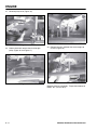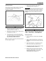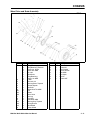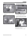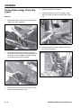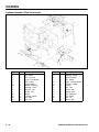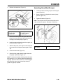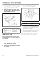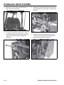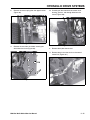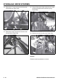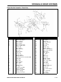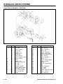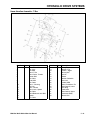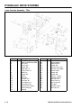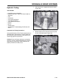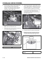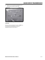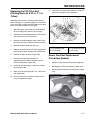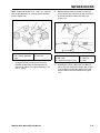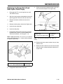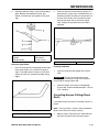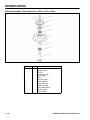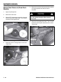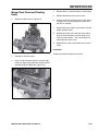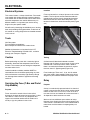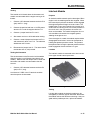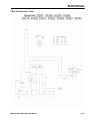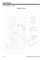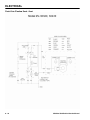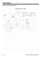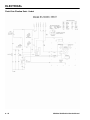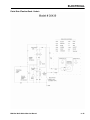
1
44947 cover
12/9/04
11:08 AM
Page 1
LCE Products
Mid-Size Walk Behind
Service Manual
492-9141
44947 cover
12/9/04
11:08 AM
Page 2
ABOUT THIS MANUAL
This manual was written for the service technician; basic mechanical/electrical skills are assumed. The Table of
Contents lists the systems and the related topics covered in this manual. The Toro Company has made every
effort to make the information in this manual complete and correct.
For service information specific to the engines used on these products, refer to the appropriate engine
manufacturer’s service and repair instructions.
Additional resources:
• Interactive Electrical Troubleshooting CD (PN 492-4757).
• Interactive Hydraulic Troubleshooting CD (PN 492-4777).
• Hydro-Gear Hydraulic Pump Service and Repair Manual (PN 492-4749).
• Ross Wheel Motor Service and Repair Manual (PN 492-4753).
We hope you will find this manual a valuable addition to your service shop. If you have any questions or comments
regarding this manual, please contact us at the following address:
The Toro Company
Landscape Contractors Equipment Division
8111 Lyndale Avenue South
Bloomington, MN 55420
The Toro Company reserves the right to change product specifications or this manual without notice.
Copyright© All Rights Reserved
©2004 The Toro Company
TABLE OF CONTENTS
Safety Information
General Information . . . . . . . . . . . . . . . . . . . . . . . . . . . . . . . . . . . . . . . . . . . . . . . . . .1 - 1
Think Safety First . . . . . . . . . . . . . . . . . . . . . . . . . . . . . . . . . . . . . . . . . . . . . . . . . . .1 - 1
Specifications & Maintenance
Torque Specifications . . . . . . . . . . . . . . . . . . . . . . . . . . . . . . . . . . . . . . . . . . . . . . . .2 - 1
Standard Torque for Dry, Zinc Plated, and Steel Fasteners (Inch Series) . . . . . . . .2 - 2
Standard Torque for Dry, Zinc, and Steel Fasteners (Metric Fasteners) . . . . . . . . .2 - 3
Other Torque Specifications . . . . . . . . . . . . . . . . . . . . . . . . . . . . . . . . . . . . . . . . . . .2 - 4
Equivalents and Conversions . . . . . . . . . . . . . . . . . . . . . . . . . . . . . . . . . . . . . . . . . .2 - 5
Product Specifications . . . . . . . . . . . . . . . . . . . . . . . . . . . . . . . . . . . . . . . . . . . . . . . .2 - 7
Product Dimensions . . . . . . . . . . . . . . . . . . . . . . . . . . . . . . . . . . . . . . . . . . . . . . . .2 - 10
Model ID . . . . . . . . . . . . . . . . . . . . . . . . . . . . . . . . . . . . . . . . . . . . . . . . . . . . . . . . .2 - 15
Maintenance Schedule, Floating Deck Models . . . . . . . . . . . . . . . . . . . . . . . . . . .2 - 16
Maintenance Schedule, Fixed Deck Models . . . . . . . . . . . . . . . . . . . . . . . . . . . . . .2 - 17
Engine
Engine Removal . . . . . . . . . . . . . . . . . . . . . . . . . . . . . . . . . . . . . . . . . . . . . . . . . . . .3 - 1
Engine Installation . . . . . . . . . . . . . . . . . . . . . . . . . . . . . . . . . . . . . . . . . . . . . . . .3 - 5
Engine Assembly, Typical . . . . . . . . . . . . . . . . . . . . . . . . . . . . . . . . . . . . . . . . . . . . .3 - 6
Chassis
Model and Serial Number Location . . . . . . . . . . . . . . . . . . . . . . . . . . . . . . . . . . . . .4 - 1
Engine Model and Serial Number Identification . . . . . . . . . . . . . . . . . . . . . . . . . . . .4 - 1
Greasing and Lubrication . . . . . . . . . . . . . . . . . . . . . . . . . . . . . . . . . . . . . . . . . . . . .4 - 1
Cleaning the Cooling System . . . . . . . . . . . . . . . . . . . . . . . . . . . . . . . . . . . . . . . . . .4 - 2
Brake Service . . . . . . . . . . . . . . . . . . . . . . . . . . . . . . . . . . . . . . . . . . . . . . . . . . . . . .4 - 3
Pistol Grip - Gear Drive - Fixed Deck . . . . . . . . . . . . . . . . . . . . . . . . . . . . . . . . . . . .4 - 3
Pistol Grip - Gear Drive - Floating Deck . . . . . . . . . . . . . . . . . . . . . . . . . . . . . . . . . .4 - 3
Pistol Grip - Hydro - Fixed Deck . . . . . . . . . . . . . . . . . . . . . . . . . . . . . . . . . . . . . . . .4 - 5
Pistol Grip - Hydro - Floating Deck . . . . . . . . . . . . . . . . . . . . . . . . . . . . . . . . . . . . . .4 - 5
T-Bar - Gear Drive - Fixed Deck . . . . . . . . . . . . . . . . . . . . . . . . . . . . . . . . . . . . . . . .4 - 6
T-Bar - Gear Drive - Floating Deck . . . . . . . . . . . . . . . . . . . . . . . . . . . . . . . . . . . . . .4 - 7
Brake Band (T-Bar - Gear Drive) . . . . . . . . . . . . . . . . . . . . . . . . . . . . . . . . . . . . . . .4 - 8
Mid-Size Walk Behind Service Manual
i
TABLE OF CONTENTS
Chassis (cont’d)
Drum Brake / Pulley Assembly Removal (Gear Drive) . . . . . . . . . . . . . . . . . . . . .
Parking Brake Linkage (Pistol Grip Hydro) . . . . . . . . . . . . . . . . . . . . . . . . . . . . . .
Fuel Tank Service . . . . . . . . . . . . . . . . . . . . . . . . . . . . . . . . . . . . . . . . . . . . . . . . .
Electric (PTO) Clutch (Floating Deck Models) . . . . . . . . . . . . . . . . . . . . . . . . . . .
Replacing the Drive Belt (Gear Drive - Floating Deck) . . . . . . . . . . . . . . . . . . . . .
Replacing the Drive Belt (Fixed Deck Pistol Grip) . . . . . . . . . . . . . . . . . . . . . . . . .
Replacing the Traction Belt (Floating Deck) . . . . . . . . . . . . . . . . . . . . . . . . . . . . .
Replacing the Traction Belt (Fixed Deck) . . . . . . . . . . . . . . . . . . . . . . . . . . . . . . .
Adjusting Grass/Mud Scraper . . . . . . . . . . . . . . . . . . . . . . . . . . . . . . . . . . . . . . . .
4 - 12
4 - 16
4 - 19
4 - 20
4 - 21
4 - 21
4 - 22
4 - 22
4 - 23
Hydraulic Drive Systems
Hydraulic Drive System Overview . . . . . . . . . . . . . . . . . . . . . . . . . . . . . . . . . . . . . . 5 - 1
Servicing the Hydraulic System . . . . . . . . . . . . . . . . . . . . . . . . . . . . . . . . . . . . . . . 5 - 3
By-Pass Valve (T-Bar) . . . . . . . . . . . . . . . . . . . . . . . . . . . . . . . . . . . . . . . . . . . . . . 5 - 6
Neutral Adjustment (T-Bar Floating Deck) . . . . . . . . . . . . . . . . . . . . . . . . . . . . . . . 5 - 7
Handle and Control Rods (T-Bar Floating Deck) . . . . . . . . . . . . . . . . . . . . . . . . . . 5 - 7
Install Control Rods . . . . . . . . . . . . . . . . . . . . . . . . . . . . . . . . . . . . . . . . . . . . . . . . . 5 - 8
Hydro Linkage Adjustments (Pistol Grip Floating Deck) . . . . . . . . . . . . . . . . . . . . 5 - 10
Speed Control Linkage (Pistol Grip Floating Deck) . . . . . . . . . . . . . . . . . . . . . . . . 5 - 10
Neutral Control Linkage Adjustment (Pistol Grip Floating Deck) . . . . . . . . . . . . . 5 - 11
Hydro Control Linkage Adjustment (Pistol Grip Floating Deck) . . . . . . . . . . . . . . 5 - 12
Control Rod Adjustment (Pistol Grip Floating Deck) . . . . . . . . . . . . . . . . . . . . . . . 5 - 14
Tracking Adjustment . . . . . . . . . . . . . . . . . . . . . . . . . . . . . . . . . . . . . . . . . . . . . . . 5 - 15
Motion Control Linkage Removal (Pistol Grip Floating Deck) . . . . . . . . . . . . . . . . 5 - 15
Hydraulic Testing . . . . . . . . . . . . . . . . . . . . . . . . . . . . . . . . . . . . . . . . . . . . . . . . . 5 - 23
Wheel Motor Removal and Installation - Floating Deck . . . . . . . . . . . . . . . . . . . . 5 - 25
Wheel Motor Removal - Fixed Deck . . . . . . . . . . . . . . . . . . . . . . . . . . . . . . . . . . . 5 - 26
Wheel Motor Installation . . . . . . . . . . . . . . . . . . . . . . . . . . . . . . . . . . . . . . . . . . . . 5 - 26
Pump Removal . . . . . . . . . . . . . . . . . . . . . . . . . . . . . . . . . . . . . . . . . . . . . . . . . . . 5 - 27
Gear Drive Transmission
Transmission Removal - Gear Drive . . . . . . . . . . . . . . . . . . . . . . . . . . . . . . . . . . . .
Control Linkage Removal (T-Bar) . . . . . . . . . . . . . . . . . . . . . . . . . . . . . . . . . . . . . .
Control Linkage Adjustment (T-Bar Gear Drive) . . . . . . . . . . . . . . . . . . . . . . . . . . .
Installing the Control Rods . . . . . . . . . . . . . . . . . . . . . . . . . . . . . . . . . . . . . . . . . . .
ii
6-1
6-5
6-6
6-7
Mid-Size Walk Behind Service Manual
TABLE OF CONTENTS
Mower Decks
Setting Up the Frame (Floating Deck) . . . . . . . . . . . . . . . . . . . . . . . . . . . . . . . . . . .7 - 1
Checking the Deck Level Side-to-Side (Floating Deck) . . . . . . . . . . . . . . . . . . . . . .7 - 2
Checking the Deck Front-to-Rear Blade Slope (Floating Deck) . . . . . . . . . . . . . . . .7 - 3
Adjusting the Deck Front-to-Rear Blade Slope . . . . . . . . . . . . . . . . . . . . . . . . . . . . .7 - 3
Adjusting the Side-to-Side Level (Fixed Deck) . . . . . . . . . . . . . . . . . . . . . . . . . . . . .7 - 4
Matching Height-of-Cut (Fixed Deck) . . . . . . . . . . . . . . . . . . . . . . . . . . . . . . . . . . . .7 - 4
Replacing the Mower Belt (Floating Deck) 36 in. (91cm) . . . . . . . . . . . . . . . . . . . . .7 - 5
Replacing the PTO Drive Belt (Floating Deck) 36 in. (91cm) . . . . . . . . . . . . . . . . . .7 - 5
Replacing the Deck Belt (Floating Deck) 44 & 52 in. (111 & 132cm) . . . . . . . . . . . .7 - 6
Replacing the PTO Drive Belt (Floating Deck) 44 & 52 in. (111 & 132cm) . . . . . . . .7 - 6
Mower Deck Belt Replacement (Fixed Deck Models) . . . . . . . . . . . . . . . . . . . . . . .7 - 7
Mower Deck Belt Guide Adjustment (Fixed Deck Models) . . . . . . . . . . . . . . . . . . .7 - 8
Replacing the Mower Belt (Fixed Deck Gear Drive) 36 in. (91cm) . . . . . . . . . . . . .7 - 8
Replacing the Mower Belt (Fixed Deck) 32 in. (81cm) . . . . . . . . . . . . . . . . . . . . . .7 - 9
Replacing the Mower Belt (Fixed Deck Gear Drive) 48 in. (122cm) . . . . . . . . . . .7 - 10
Mower Deck Drive Belt Adjustment (Fixed Deck Models) . . . . . . . . . . . . . . . . . . .7 - 12
Blade Engagement Adjustment (Fixed Deck) . . . . . . . . . . . . . . . . . . . . . . . . . . . . .7 - 13
Blade Safety Switch Adjustment (Fixed Deck) . . . . . . . . . . . . . . . . . . . . . . . . . . . .7 - 14
Adjusting the Blade Brake (Fixed Deck) . . . . . . . . . . . . . . . . . . . . . . . . . . . . . . . . .7 - 14
Replacing the Mower Belt (Fixed Deck Hydro, Pistol Grips) . . . . . . . . . . . . . . . . .7 - 15
Adjusting Mower Belt Tension (Fixed Deck) - All . . . . . . . . . . . . . . . . . . . . . . . . . .7 - 16
Servicing the Cutting Blades (All Models) . . . . . . . . . . . . . . . . . . . . . . . . . . . . . . . .7 - 17
Correcting Uneven Cutting (Fixed Deck) . . . . . . . . . . . . . . . . . . . . . . . . . . . . . . . .7 - 19
Replace Spindle Bearings (Fixed Deck) . . . . . . . . . . . . . . . . . . . . . . . . . . . . . . . . .7 - 20
Replace Spindle Bearings (Floating Deck) . . . . . . . . . . . . . . . . . . . . . . . . . . . . . . .7 - 21
Replacing the Castor Wheel Fork Bushings (All Models) . . . . . . . . . . . . . . . . . . . .7 - 26
Castor Wheel and Bearings Service (Floating Deck) . . . . . . . . . . . . . . . . . . . . . . .7 - 26
Replacing the Grass Deflector (All Models) . . . . . . . . . . . . . . . . . . . . . . . . . . . . . .7 - 27
Mower Deck Removal (Fixed Deck Models) . . . . . . . . . . . . . . . . . . . . . . . . . . . . . .7 - 28
Mower Deck Removal (Floating Deck) . . . . . . . . . . . . . . . . . . . . . . . . . . . . . . . . . .7 - 29
Electrical
Electrical Systems . . . . . . . . . . . . . . . . . . . . . . . . . . . . . . . . . . . . . . . . . . . . . . . . . .8 - 2
Tools . . . . . . . . . . . . . . . . . . . . . . . . . . . . . . . . . . . . . . . . . . . . . . . . . . . . . . . . . . . . .8 - 2
Caution . . . . . . . . . . . . . . . . . . . . . . . . . . . . . . . . . . . . . . . . . . . . . . . . . . . . . . . . . . .8 - 2
Servicing the Fuse (T-Bar and Pistol Grip Models) . . . . . . . . . . . . . . . . . . . . . . . . .8 - 2
Relay . . . . . . . . . . . . . . . . . . . . . . . . . . . . . . . . . . . . . . . . . . . . . . . . . . . . . . . . . . . . .8 - 2
Solenoid . . . . . . . . . . . . . . . . . . . . . . . . . . . . . . . . . . . . . . . . . . . . . . . . . . . . . . . . . .8 - 4
Ignition Switch . . . . . . . . . . . . . . . . . . . . . . . . . . . . . . . . . . . . . . . . . . . . . . . . . . . . . .8 - 5
Electric PTO Clutch . . . . . . . . . . . . . . . . . . . . . . . . . . . . . . . . . . . . . . . . . . . . . . . . .8 - 6
Testing the Clutch Power Supply . . . . . . . . . . . . . . . . . . . . . . . . . . . . . . . . . . . . . . .8 - 7
PTO Switch Test . . . . . . . . . . . . . . . . . . . . . . . . . . . . . . . . . . . . . . . . . . . . . . . . . . .8 - 10
Transmission Switch (Gear Drive) . . . . . . . . . . . . . . . . . . . . . . . . . . . . . . . . . . . . .8 - 10
Mid-Size Walk Behind Service Manual
iii
TABLE OF CONTENTS
Electrical (cont’d)
Hourmeter . . . . . . . . . . . . . . . . . . . . . . . . . . . . . . . . . . . . . . . . . . . . . . . . . . . . . . .
Switch (65-7410 & 1-513051) . . . . . . . . . . . . . . . . . . . . . . . . . . . . . . . . . . . . . . . .
Switch (95-1653) . . . . . . . . . . . . . . . . . . . . . . . . . . . . . . . . . . . . . . . . . . . . . . . . . .
Bail Switch (82-2190) . . . . . . . . . . . . . . . . . . . . . . . . . . . . . . . . . . . . . . . . . . . . . .
Rocker Switch (82-2300) . . . . . . . . . . . . . . . . . . . . . . . . . . . . . . . . . . . . . . . . . . . .
Bridge Rectifier . . . . . . . . . . . . . . . . . . . . . . . . . . . . . . . . . . . . . . . . . . . . . . . . . . .
Delay Module (2000 and Earlier) . . . . . . . . . . . . . . . . . . . . . . . . . . . . . . . . . . . . .
Delay Module 104-8141 (T-Bar Floating Deck Electric Clutch 2001 & Up . . . . . . .
Interlock Module . . . . . . . . . . . . . . . . . . . . . . . . . . . . . . . . . . . . . . . . . . . . . . . . . .
Wiring Diagrams
T-Bar (Fixed Deck - Gear) . . . . . . . . . . . . . . . . . . . . . . . . . . . . . . . . . . . . . . . . . . .
T-Bar (Fixed Deck - Gear) . . . . . . . . . . . . . . . . . . . . . . . . . . . . . . . . . . . . . . . . . . .
T-Bar (Fixed Deck - Gear) . . . . . . . . . . . . . . . . . . . . . . . . . . . . . . . . . . . . . . . . . . .
T-Bar (Fixed Deck - Gear) . . . . . . . . . . . . . . . . . . . . . . . . . . . . . . . . . . . . . . . . . . .
T-Bar (Floating Deck - Gear) . . . . . . . . . . . . . . . . . . . . . . . . . . . . . . . . . . . . . . . . .
T-Bar (Floating Deck - Gear) . . . . . . . . . . . . . . . . . . . . . . . . . . . . . . . . . . . . . . . . .
T-Bar (Floating Deck - Gear) . . . . . . . . . . . . . . . . . . . . . . . . . . . . . . . . . . . . . . . . .
T-Bar (Floating Deck - Gear) . . . . . . . . . . . . . . . . . . . . . . . . . . . . . . . . . . . . . . . . .
T-Bar (Floating Deck - Gear) . . . . . . . . . . . . . . . . . . . . . . . . . . . . . . . . . . . . . . . . .
T-Bar (Floating Deck - Gear and 1988 / 1999 Hydro) . . . . . . . . . . . . . . . . . . . . . .
T-Bar (Floating Deck - Hydro) . . . . . . . . . . . . . . . . . . . . . . . . . . . . . . . . . . . . . . . .
T-Bar (Floating Deck - Hydro) . . . . . . . . . . . . . . . . . . . . . . . . . . . . . . . . . . . . . . . .
T Bar (Floating Deck - Hydro) . . . . . . . . . . . . . . . . . . . . . . . . . . . . . . . . . . . . . . . .
T-Bar (Floating Deck - Hydro) . . . . . . . . . . . . . . . . . . . . . . . . . . . . . . . . . . . . . . . .
T-Bar (Floating Deck - Hydro) . . . . . . . . . . . . . . . . . . . . . . . . . . . . . . . . . . . . . . . .
Pistol Grip (Fixed Deck - Gear) . . . . . . . . . . . . . . . . . . . . . . . . . . . . . . . . . . . . . . .
Pistol Grip (Fixed Deck - Gear) . . . . . . . . . . . . . . . . . . . . . . . . . . . . . . . . . . . . . . .
Pistol Grip (Fixed Deck - Gear) . . . . . . . . . . . . . . . . . . . . . . . . . . . . . . . . . . . . . . .
Pistol Grip (Fixed Deck - Hydro) . . . . . . . . . . . . . . . . . . . . . . . . . . . . . . . . . . . . . .
Pistol Grip (Fixed Deck - Hydro) . . . . . . . . . . . . . . . . . . . . . . . . . . . . . . . . . . . . . .
Pistol Grip (Floating Deck - Gear) . . . . . . . . . . . . . . . . . . . . . . . . . . . . . . . . . . . . .
Pistol Grip (Floating Deck - Gear) . . . . . . . . . . . . . . . . . . . . . . . . . . . . . . . . . . . . .
Pistol Grip (Floating Deck - Hydro) . . . . . . . . . . . . . . . . . . . . . . . . . . . . . . . . . . . .
Pistol Grip (Floating Deck - Hydro) . . . . . . . . . . . . . . . . . . . . . . . . . . . . . . . . . . . .
Pistol Grip (Floating Deck - Hydro) . . . . . . . . . . . . . . . . . . . . . . . . . . . . . . . . . . . .
Pistol Grip (Floating Deck - Hydro) . . . . . . . . . . . . . . . . . . . . . . . . . . . . . . . . . . . .
Pistol Grip (Floating Deck - Hydro) . . . . . . . . . . . . . . . . . . . . . . . . . . . . . . . . . . . .
Pistol Grip (Floating Deck - Hydro) . . . . . . . . . . . . . . . . . . . . . . . . . . . . . . . . . . . .
Pistol Grip (Floating Deck - Hydro) . . . . . . . . . . . . . . . . . . . . . . . . . . . . . . . . . . . .
Pistol Grip (Floating Deck - Hydro) . . . . . . . . . . . . . . . . . . . . . . . . . . . . . . . . . . . .
iv
8 - 11
8 - 11
8 - 12
8 - 12
8 - 12
8 - 13
8 - 14
8 - 14
8 - 15
8 - 16
8 - 17
8 - 18
8 - 19
8 - 20
8 - 21
8 - 22
8 - 22
8 - 23
8 - 24
8 - 26
8 - 27
8 - 28
8 - 29
8 - 30
8 - 31
8 - 32
8 - 33
8 - 34
8 - 35
8 - 36
8 - 37
8 - 38
8 - 39
8 - 40
8 - 41
8 - 42
8 - 43
8 - 44
8 - 45
Mid-Size Walk Behind Service Manual
SAFETY INFORMATION
General Information
This symbol means WARNING or
PERSONAL SAFETY INSTRUCTION read the instruction because it has to
do with your safety. Failure to comply
with the instruction may result in
personal injury or even death.
This manual is intended as a service and repair
manual only. The safety instructions provided herein
are for troubleshooting, service, and repair of the MidSize Walk Behind mower. The Mid-Size Walk Behind
Mower and attachment operator’s manuals contain
safety information and operating tips for safe operating
practices. Operator’s manuals are available through
your Toro parts source or:
The Toro Company
Publications Department
8111 Lyndale Avenue South
Bloomington, MN 55420
Think Safety First
Avoid unexpected starting of engine...
Avoid injury from batteries...
Always turn off the engine and disconnect the spark
plug wire(s) before cleaning, adjusting, or repair.
Battery acid is poisonous and can cause burns. Avoid
contact with skin, eyes, and clothing. Battery gases
can explode. Keep cigarettes, sparks, and flames away
from the battery.
Avoid lacerations and amputations...
Stay clear of all moving parts whenever the engine is
running. Treat all normally moving parts as if they were
moving whenever the engine is running or has the
potential to start.
Avoid injury due to inferior parts...
Use only original equipment parts to ensure that
important safety criteria are met.
Avoid burns...
Avoid injury to bystanders...
Do not touch the engine, muffler, or other components
which may increase in temperature during operation,
while the unit is running or shortly after it has been
running.
Always clear the area of bystanders before starting or
testing powered equipment.
Avoid fires and explosions...
Always clear the area of sticks, rocks, or any other
debris that could be picked up and thrown by the
powered equipment.
Avoid spilling fuel and never smoke while working with
any type of fuel or lubricant. Wipe up any spilled fuel or
oil immediately. Never remove the fuel cap or add fuel
when the engine is running. Always use approved,
labeled containers for storing or transporting fuel and
lubricants.
Avoid injury due to projectiles...
Avoid modifications...
Never alter or modify any part unless it is a factory
approved procedure.
Avoid asphyxiation...
Avoid unsafe operation...
Never operate an engine in a confined area without
proper ventilation.
Always test the safety interlock system after making
adjustments or repairs on the machine. Refer to the
Electrical section in this manual for more information.
Mid-Size Walk Behind Service Manual
1-1
THIS PAGE INTENTIONALLY LEFT BLANK
1-2
Mid-Size Walk Behind Service Manual
SPECIFICATIONS
Torque Specifications
Fastener Identification
Recommended fastener torque values are listed in the
following tables. For critical applications, as
determined by Toro, either the recommended torque or
a torque that is unique to the application is clearly
identified and specified in the service manual.
These torque specifications for the installation and
tightening of fasteners shall apply to all fasteners which
do not have a specific requirement identified in the
service manual. The following factors shall be
considered when applying torque: cleanliness of the
fastener, use of a thread sealant (Loctite), degree of
lubrication on the fastener, presence of a prevailing
torque feature, hardness of the surface underneath of
the fastener’s head, or similar condition which affects
the installation.
As noted in the following tables, torque values should
be reduced by 25% for lubricated fasteners to
achieve the similar stress as a dry fastener. Torque
values may also have to be reduced when the fastener
is threaded into aluminum or brass. The specific
torque value should be determined based on the
aluminum or brass material strength, fastener size,
length of thread engagement, etc.
Figure 1
Inch Series Bolts and Screws
(A) Grade 1 & 2
(B) Grade 5
(C) Grade 8
The standard method of verifying torque shall be
performed by marking a line on the fastener (head or
nut) and mating part, then back off fastener 1/4 of a
turn. Measure the torque required to tighten the
fastener until the lines match up.
Figure 2
Metric Bolts and Screws
(A) Class 8.8
Mid-Size Walk Behind Service Manual
(B) Class 10.9
2-1
SPECIFICATIONS
Standard Torque for Dry, Zinc Plated, and Steel Fasteners (Inch Series)
Thread Size
Grade 1, 5, & SAE Grade 1 Bolts, Screws, SAE Grade 5 Bolts, Screws, SAE Grade 8 Bolts, Screws,
8 with Thin Studs, & Sems with Regular Studs, & Sems with Regular Studs, & Sems with Regular
Height Nuts
Height Nuts (SAE J995
Height Nuts (SAE J995
Height Nuts (SAE J995
Grade 2 or Stronger Nuts)
Grade 2 or Stronger Nuts)
Grade 2 or Stronger Nuts)
In-lb
# 6 - 32 UNC
# 6 - 40 UNF
# 8 - 32 UNC
# 8 - 36 UNF
# 10 - 24 UNC
#10 - 32 UNF
In-lb
N-cm
10 ± 2
13 ± 2
147 ± 23
13 ± 2
25 ± 5
282 ± 30
18 ± 2
30 ± 5
339 ± 56
In-lb
N-cm
In-lb
N-cm
15 ± 2
169 ± 23
23 ± 2
260 ± 34
17 ± 2
190 ± 20
25 ± 2
280 ± 20
29 ± 3
330 ± 30
41 ± 4
460 ± 45
31 ± 3
350 ± 30
43 ± 4
31 ± 3
42 ± 4
475 ± 45
60 ± 6
674 ± 70
48 ± 4
540 ± 45
68 ± 6
765 ± 70
1/4 - 20 UNC
48 ± 7
53 ± 7
599 ± 79
100 ± 10
1125 ± 100
140 ± 15
1580 ± 170
1/4 - 28 UNF
53 ± 7
65 ± 10
734 ± 113
115 ± 10
1300 ± 100
160 ± 15
1800 ± 170
5/16 - 18 UNC
115 ± 15
105 ± 15
1186 ± 169
200 ± 25
2250 ± 280
300 ± 30
3390 ± 340
5/16 - 24 UNF
138 ± 17
128 ± 17
1446 ± 192
225 ± 25
2540 ± 280
325 ± 30
3670 ± 340
ft-lb
ft-lb
N-m
ft-lb
N-m
ft-lb
N-m
3/8 - 16 UNC
16 ± 2
16 ± 2
22 ± 3
30 ± 3
41 ± 4
43 ± 4
58 ± 5
3/8 - 24 UNF
17 ± 2
18 ± 2
24 ± 3
35 ± 3
47 ± 4
50 ± 4
68 ± 5
7/16 - 14 UNC
27 ± 3
27 ± 3
37 ± 4
50 ± 5
68 ± 7
70 ± 7
68 ± 9
7/16 - 20 UNF
29 ± 3
29 ± 3
39 ± 4
55 ± 5
75 ± 7
77 ± 7
104 ± 9
1/2 - 13 UNC
30 ± 3
48 ± 7
65 ± 9
75 ± 8
102 ± 11
105 ± 10
142 ± 14
1/2 - 20 UNF
32 ± 3
53 ± 7
72 ± 9
85 ± 8
115 ± 11
120 ± 10
163 ± 14
5/8 - 11 UNC
65 ± 10
88 ± 12
119 ± 16
150 ± 15
203 ± 20
210 ± 20
285 ± 27
5/8 - 18 UNF
75 ± 10
95 ± 15
129 ± 20
170 ± 15
230 ± 20
240 ± 20
325 ± 27
3/4 - 10 UNC
93 ± 12
140 ± 20
190 ± 27
265 ± 25
359 ± 34
374 ± 35
508 ± 47
3/4 - 16 UNF
115 ± 15
165 ± 25
224 ± 34
300 ± 25
407 ± 34
420 ± 35
569 ± 47
7/8 - 9 UNC
140 ± 20
225 ± 25
305 ± 34
430 ± 45
583 ± 61
600 ± 60
813 ± 81
7/8 - 14 UNF
155 ± 25
260 ± 30
353 ± 41
475 ± 45
644 ± 61
660 ± 60
895 ± 81
Note: Reduce torque values listed in the table above
by 25% for lubricated fasteners. Lubricated fasteners
are defined as threads coated with a lubricant such as
oil, graphite, or thread sealant such as Loctite.
Note: The nominal torque values listed above for
Grade 5 and 8 fasteners are based on 75% of the
minimum proof load specified in SAE J429. The
tolerance is approximately ± 10% of the nominal torque
value. Thin height nuts include jam nuts.
Note: Torque values may have to be reduced when
installing fasteners into threaded aluminum or brass.
The specific torque value should be determined based
on the fastener size, the aluminum or base material
strength, length of thread engagement, etc.
2-2
Mid-Size Walk Behind Service Manual
SPECIFICATIONS
Standard Torque for Dry, Zinc, and Steel Fasteners (Metric Fasteners)
Thread Size
Class 8.8 Bolts, Screws, and Studs with
Regular Height Nuts
(Class 8 or Strong Nuts)
Class 10.9 Bolts, Screws, and Studs with
Regular Height Nuts (
Class 10 or Strong Nuts)
M5 X 0.8
57 ± 5 in-lb
644 ± 68 N-cm
78 ± 8 in-lb
881 ± 90 N-cm
M6 X 1.0
96 ± 10 in-lb
1085 ± 113 N-cm
133 ± 14 in-lb
1503 ± 158 N-cm
M8 X 1.25
19 ± 2 ft-lb
26 ± 3 N-m
28 ± 3 ft-lb
38 ± 4 N-m
M10 X 1.5
38 ± 4 ft-lb
52 ± 5 N-m
54 ± 6 ft-lb
73 ± 8 N-m
M12 X 1.75
66 ± 7 ft-lb
90 ± 10 N-m
93 ± 10 ft-lb
126 ± 14 N-m
M16 X 2.0
166 ± 15 ft-lb
225 ± 23 N-m
229 ± 23 ft-lb
310 ± 31 N-m
M20 X 2.5
325 ± 33 ft-lb
440 ± 45 N-m
450 ± 36 ft-lb
610 ± 62 N-m
Note: Reduce torque values listed in the table above
by 25% for lubricated fasteners. Lubricated fasteners
are defined as threads coated with a lubricant such as
oil, graphite, or thread sealant such as Loctite.
Note: The nominal torque values listed above are
based on 75% of the minimum proof load specified in
SAE J1199. The tolerance is approximately ± 10% of
the nominal torque value. Thin height nuts include jam
nuts.
Note: Torque values may have to be reduced when
installing fasteners into threaded aluminum or brass.
The specific torque value should be determined based
on the fastener size, the aluminum or base material
strength, length of thread engagement, etc.
Mid-Size Walk Behind Service Manual
2-3
SPECIFICATIONS
Other Torque Specifications
Wheel Bolts and Lug Nuts
SAE Grade 8 Steel Set Screws
Recommended Torque
Thread Size
Recommended Torque**
Thread Size
Square Head
Hex Socket
1/4 - 20 UNC
140 ± 20 in-lb
73 ± 12 in-lb
5/16 - 18 UNC
215 ± 35 in-lb
145 ± 20 in-lb
3/8 - 16 UNC
35 ± 10 ft-lb
18 ± 3 ft-lb
1/2 - 13 UNC
75 ± 15 ft-lb
50 ± 10 ft-lb
7/16 - 20 UNF
Grade 5
65 ± 10 ft-lb
88 ± 14 N-m
1/2 - 20 UNF
Grade 5
80 ± 10 ft-lb
108 ± 14 N-m
M12 X 1.25
Class 8.8
80 ± 10 ft-lb
108 ± 14 N-m
M12 X 1.5
Class 8.8
80 ± 10 ft-lb
108 ± 14 N-m
** For steel wheels and non-lubricated fasteners.
Thread Cutting Screws
(Zinc Plated Steel)
Thread Cutting Screws
(Zinc Plated Steel)
Type 1, Type 23, or Type F
Threads per Inch
Thread
Size
Type A
Baseline Torque*
Type B
Thread Size
Baseline Torque*
No. 6 - 32 UNC
20 ± 5 in-lb
No. 6
18
20
20 ± 5 in-lb
No. 8 - 32 UNC
30 ± 5 in-lb
No. 8
15
18
30 ± 5 in-lb
No.10 - 24 UNC
38 ± 7 in-lb
No. 10
12
16
38 ± 7 in-lb
1/4 - 20 UNC
85 ± 15 in-lb
No. 12
11
14
85 ± 15 in-lb
5/16 - 18 UNC
110 ± 20 in-lb
3/8 - 16 UNC
200 ± 100 in-lb
* Hole size, material strength, material thickness and
finish must be considered when determining specific
torque values. All torque values are based on nonlubricated fasteners.
Conversion Factors
in-lb X 11.2985 = N-cm
ft-lb X 1.3558 = N-m
2-4
N-cm X - 0.08851 = in-lb
N-cm X 0.73776 = ft-lb
Mid-Size Walk Behind Service Manual
SPECIFICATIONS
Equivalents and Conversions
Decimal and Millimeter Equivalents
Fractions
1/64
1/32
3/64
1/16
5/64
3/32
1/8
9/64
5/32
11/64
3/16
13/64
7/32
15/64
1/4
17/64
9/32
19/64
5/16
21/64
11/32
23/64
3/8
25/64
13/32
27/64
7/16
29/64
15/32
31/64
1/2
Decimals
mm
0.015625
0.397
0.03125
0.794
0.046875
1.191
0.0625
1.588
0.078125
1.984
0.9375
2.381
0.1250
3.175
0.140625
3.572
0.15625
3.969
0.171875
4.366
0.1875
4.762
0.203125
5.159
0.21875
5.556
0.234375
5.953
0.2500
6.350
0.265625
6.747
0.28125
7.144
0.296875
7.541
0.3125
7.541
0.328125
8.334
0.34375
8.731
0.359375
9.128
0.3750
9.525
0.390625
9.922
0.40625
10.319
0.421875
10.716
0.4375
11.112
0.453125
11.509
0.46875
11.906
0.484375
12.303
0.5000
12.700
1 mm = 0.03937 in.
Mid-Size Walk Behind Service Manual
Fractions
33/64
16/32
35/64
9/16
37/64
19/32
5/8
41/64
21/32
43/64
11/16
45/64
23/32
47/64
3/4
49/64
25/32
51/64
13/16
53/64
27/32
55/64
7/8
57/64
29/32
59/64
15/16
61/64
31/32
63/64
1
Decimals
mm
0.515625
13.097
0.53125
13.484
0.546875
13.891
0.5625
14.288
0.578125
14.684
0.59375
15.081
0.6250
15.875
0.640625
16.272
0.65625
16.669
0.671875
17.066
0.6875
17.462
0.703125
17.859
0.71875
18.256
0.734375
18.653
0.7500
19.050
0.765625
19.447
0.78125
19.844
0.796875
20.241
0.8125
20.638
0.828125
21.034
0.84375
21.431
0.859375
21.828
0.8750
22.225
0.890625
22.622
0.90625
23.019
0.921875
23.416
0.9375
23.812
0.953125
24.209
0.96875
24.606
0.984375
25.003
1.000
25.400
0.001 in. = 0.0254 mm
2-5
SPECIFICATIONS
U.S. to Metric Conversions
To Convert
Into
Linear
Measurement
Miles
Yards
Feet
Feet
Inches
Inches
Inches
Kilometers
Meters
Meters
Centimeters
Meters
Centimeters
Millimeters
Area
Square Miles
Square Feet
Square Inches
Acre
Square Kilometers
Square Meters
Square Centimeters
Hectare
Volume
Cubic Yards
Cubic Feet
Cubic Inches
Cubic Meters
Cubic Meters
Cubic Centimeters
0.7646
0.02832
16.39
Weight
Tons (Short)
Pounds
Ounces
Metric Tons
Kilograms
Grams
0.9078
0.4536
28.3495
Pressure
Pounds/Sq. In.
Kilopascal
6.895
Work
Foot-pounds
Foot-pounds
Inch-pounds
Newton-Meters
Kilogram-Meters
Kilogram-Centimeters
1.356
0.1383
1.152144
Liquid Volume
Quarts
Gallons
Liters
Liters
0.9463
3.785
Liquid Flows
Gallons/Minute
Liters/Minute
3.785
Fahrenheit
Celsius
Temperature
2-6
Multiply By
1.609
0.9144
0.3048
30.48
0.0254
2.54
25.4
2.59
0.0929
6.452
0.4047
1. Subtract 32°
2. Multiply by 5/9
Mid-Size Walk Behind Service Manual
Engine Make
Kawasaki
Kawasaki
Kohler
Kawasaki
Briggs & Stratton
Kawasaki
Kawasaki
Kawasaki
Kawasaki
Kohler
Kohler
Briggs & Stratton
Kohler
Kohler
Kohler
Briggs & Stratton
Briggs & Stratton
Kohler
Kawasaki
Kohler
Kawasaki
Kawasaki
Kohler
Kawasaki
Kohler
Kohler
Kohler
Kohler
Kawasaki
Kawasaki
Kawasaki
Kawasaki
Kohler
Kohler
Kohler
Model
30140
30150
30159
30161
30164
30167
30168
30169
30171
30177
30178
30182
30183
30184
30187
30188
30189
30192
30193
30194
30195
30196
30197
30250
30252
30253
30254
30255
30257
30258
30259
30260
30290
30291
30292
Horse Oil Capacity w/
Power Filter Change
15
58 oz. (1.7 l)
13
58 oz. (1.7 l)
15
64 oz. (1.9 l)
13
58 oz. (1.7 l)
10.5
48 oz. (1.4 l)
12.5
48 oz. (1.4 l)
15
58 oz. (1.7 l)
17
58 oz. (1.7 l)
12.5
48 oz. (1.4 l)
15
64 oz. (1.9 l)
15
64 oz. (1.9 l)
16
56 oz. (1.7 l)
18
64 oz. (1.9 l)
13
64 oz. (1.9 l)
15
64 oz. (1.9 l)
16
56 oz. (1.7 l)
16
56 oz. (1.7 l)
20
64 oz. (1.9 l)
12.5
48 oz. (1.4 l)
13
64 oz. (1.9 l)
15
58 oz. (1.7 l)
14
54 oz. (1.6 l)
15
64 oz. (1.9 l)
12.5
48 oz. (1.4 l)
13
64 oz. (1.9 l)
15
64 oz. (1.9 l)
15
64 oz. (1.9 l)
15
64 oz. (1.9 l)
15
58 oz. (1.7 l)
15
58 oz. (1.7 l)
17
58 oz. (1.7 l)
17
58 oz. (1.7 l)
15
64 oz. (1.9 l)
15
64 oz. (1.9 l)
15
64 oz. (1.9 l)
Product Specifications
RPM High RPM Low
Deck
Fixed
Speed
Speed
Deck
3600+-100
1550
48” SD
X
3600+-100
1550
32" SD
X
3200+-100 1400+-200
3600+-100
1550
36" SD
X
3600+-100
--32" SD
X
3,350
1400
3200+-100
1400
3200+-100
1400
3600+-100
1400
32" SD
X
3600+-100 900 to 1,000
3600+-50 1400+-200
36" SD
X
3200+-100 1400+-200
3250+-75
1400+-75
3600+-50
1500
91cm SD
X
3200+-100 1400+-200
3200+-100 1400+-200
3200+-100 1400+-200
3200+-100 1400+-200
3600+-100
1400
36" SD
X
3600+-50 1400+-200
36" SD
X
3600+-100
1550
48" SD
X
3600+-100
1550
48" SD
X
3600+-50 1400+-200
48" SD
X
3600+-100
1400
36" SD
3200+-100 1400+-200
32" SD
3600+-50
1550
36" SD
3600+-50 1400+-200
44" SD
3600+-50 1400+-200
52" SD
3600+-100
1550
44" SD
3600+-100
1550
52" SD
3600+-100
1550
44" SD
3600+-100
1550
52" SD
3600+-50 1400+-200
36" SD
3600+-50 1400+-200
44" SD
3600+-50 1400+-200
52" SD
Floating Traction Gear Hydro Chassis PG T-Bar
Deck
Unit
Drive Drive
X
X
X
X
X
X
X
X
X
X
X
X
X
X
X
X
X
X
X
X
X
X
X
X
X
X
X
X
X
X
X
X
X
X
X
X
X
X
X
X
X
X
X
X
X
X
X
X
X
X
X
X
X
X
X
X
X
X
X
X
X
X
X
X
X
X
X
X
X
X
X
X
X
X
X
X
X
X
X
X
X
X
X
X
X
X
X
X
X
X
X
X
X
SPECIFICATIONS
Mid-Size Walk Behind Service Manual
2-7
Engine Make
Kawasaki
Kawasaki
Kohler
Kohler
Kohler
Kohler
Kawasaki
Kawasaki
Kawasaki
Kawasaki
Kawasaki
Kohler
Kawasaki
Kawasaki
Kawasaki
Kohler
Kawasaki
Kawasaki
Kawasaki
Kawasaki
Kawasaki
Kohler
Kawasaki
Kawasaki
Kohler
Kawasaki
Kawasaki
Kawasaki
Kawasaki
Kawasaki
Kawasaki
Kawasaki
Kawasaki
Kawasaki
Kawasaki
Kawasaki
Model
30297
30314
30316
30317
30318
30319
30320
30321
30322
30326
30327
30329
30332
30333
30334
30335
30338
30339
30340
30341
30342
30430
30431
30432
30433
30434
30435
30436
30437
30438
30439
30440
30441
30518
30519
30520
Horse Oil Capacity w/
Power Filter Change
17
58 oz. (1.7 l)
13
60 oz. (1.8 l)
13
64 oz. (1.9 l)
15
64 oz. (1.9 l)
15
64 oz. (1.9 l)
15
64 oz. (1.9 l)
15
58 oz. (1.7 l)
17
58 oz. (1.7 l)
17
58 oz. (1.7 l)
15
58 oz. (1.7 l)
17
58 oz. (1.7 l)
15
64 oz. (1.9 l)
15
58 oz. (1.7 l)
15
58 oz. (1.7 l)
17
58 oz. (1.7 l)
15
64 oz. (1.9 l)
15
64 oz. (1.9 l)
15
64 oz. (1.9 l)
17
58 oz. (1.7 l)
17
58 oz. (1.7 l)
17
58 oz. (1.7 l)
15
64 oz. (1.9 l)
15
58 oz. (1.7 l)
17
58 oz. (1.7 l)
15
64 oz. (1.9 l)
15
58 oz. (1.7 l)
17
58 oz. (1.7 l)
17
58 oz. (1.7 l)
15
58 oz. (1.7 l)
17
58 oz. (1.7 l)
15
58 oz. (1.7 l)
17
58 oz. (1.7 l)
17
58 oz. (1.7 l)
13
58 oz. (1.7 l)
13
58 oz. (1.7 l)
12.5
48 oz. (1.4 l)
RPM High
Speed
3600+-100
3600+-100
3200+-100
3600+-50
3600+-50
3600+-50
3600+-100
3600+-100
3600+-100
3600+-100
3600+-100
3600+-50
3600+-100
3600+-100
3600+-100
3600+-50
3600+-100
3600+-100
3600+-100
3600+-100
3600+-100
3600+-50
3600+-100
3600+-100
3600+-50
3600+-100
3600+-100
3600+-100
3600+-100
3600+-100
3600+-100
3600+-100
3600+-100
3600+-100
3600+-100
3600+-50
2-8
1550
1550
1550
1550
1400+-200
1550
1550
1400+-200
1550
1550
1550
1550
1550
1550
1550
1550
1550
1550
1400
RPM Low
Speed
1550
1550
1400+-200
1400+-200
1400+-200
1400+-200
1550
1550
1550
1550
1550
1400+-200
1550
1550
1550
1400+-200
52" SD
91cm SD
32" SD
36" SD
44" SD
52" SD
44" SD
44" SD
52" SD
44" SD
44" SD
36" SD
44" SD
52" SD
52" SD
36" SD
44" SD
52" SD
44" SD
52" SD
52" SD
36" SD
44" SD
52" SD
36" SD
44" SD
44" SD
52" SD
44" SD
52" SD
44" SD
44" SD
52" SD
32" SD
36" SD
32" SD
Deck
X
X
X
Fixed
Deck
Floating Traction Gear Hydro Chassis PG T-Bar
Deck
Unit
Drive Drive
X
X
X
X
X
X
X
X
X
X
X
X
X
X
X
X
X
X
X
X
X
X
X
X
X
X
X
X
X
X
X
X
X
X
X
X
X
X
X
X
X
X
X
X
X
X
X
X
X
X
X
X
X
X
X
X
X
X
X
X
X
X
X
X
X
X
X
X
X
X
X
X
X
X
X
X
X
X
X
X
X
X
X
X
X
X
X
X
X
X
X
X
X
X
X
X
X
X
X
X
X
X
X
X
X
SPECIFICATIONS
Mid-Size Walk Behind Service Manual
Engine Make
Kawasaki
Kawasaki
Kawasaki
Kawasaki
Kohler
Kohler
Kohler
Kohler
Kawasaki
Kawasaki
Kawasaki
Kawasaki
Kohler
Kawasaki
Model
30521
30523
30524
30526
30527
30528
30529
30530
30531
30172TE
30250TE
30261TE
30291TE
30299TE
Horse Oil Capacity w/
Power Filter Change
12.5
48 oz. (1.4 l)
15
58 oz. (1.7 l)
15
58 oz. (1.7 l)
15
58 oz. (1.7 l)
15
64 oz. (1.9 l)
15
64 oz. (1.9 l)
15
64 oz. (1.9 l)
15
64 oz. (1.9 l)
15
58 oz. (1.7 l)
12.5
54 oz. (1.6 l)
12.5
54 oz. (1.6 l)
12.5
54 oz. (1.6 l)
15
64 oz. (1.9 l)
15
58 oz. (1.7 l)
RPM High
Speed
3600+-50
3600+-100
3600+-100
3600+-100
3600+-50
3600+-100
3600+-50
3600+-50
3600+-100
2800
2800
2760
2800
2800+-100
RPM Low
Speed
1400
1550
1550
1550
1400+-200
1400+-200
1400+-200
1400+-200
1550
1400
1400
1400
1400+-200
1400+-200
36" SD
91cm SD
44" SD
112cm
SD
36" SD
48" SD
36" SD
48" SD
36" SD
48" SD
36" SD
48" SD
48" SD
Deck
Fixed
Deck
X
X
X
X
X
X
X
X
X
Floating Traction Gear Hydro Chassis PG T-Bar
Deck
Unit
Drive Drive
X
X
X
X
X
X
X
X
X
X
X
X
X
X
X
X
X
X
X
X
X
X
X
X
X
X
X
X
X
X
X
X
X
SPECIFICATIONS
Mid-Size Walk Behind Service Manual
2-9
2 - 10
2004
2004
1997-2000
2004
2000-2002
1996-2002
2000
2000, 2002 &
2004
2000-2003
30140
30150
30159
30161
30164
30167
30168
30169
1996-1999
1996-1999
1998-2000
30182
30183
30184
1997-2000 &
02 & 04
1997 & 2000
1997-1998
1997-1998 &
02
1997-2000
1998-2002
2003
30188
30189
30192
30193
30194
30195
30187
30178
1996-2002 &
2004
2003-2004
30177
30171
Years
Model
35.0"
46"
46"
33.0"
33.0”
33.0”
33.0”
35.0"
35.0"
35.0"
35.0"
35.0"
42"
35.0"
35.0"
35.0"
42"
30.0"
35.0"
32.0"
35.0"
Width
Product Dimensions
41"
41"
41"
44.5"
44.5”
44.5”
44.5”
44.5"
44.5"
41.0"
41"
44.5"
41"
44.5"
44.5"
44.5"
41"
43.5"
41"
40"
41"
Height
72"
74"
74"
43.0"
43.0”
43.0”
43.0”
40.0"
45.0"
74.0"
74"
40.0"
78"
45.0"
40.0"
40.0"
78"
40.0"
74"
74"
72"
Length
435
392
392
375
340
340
340
270
294
392
392
261
374
260
270
270
374
258
392
374
435
Weight
(lbs.)
9"x3.5-4"
9"x3.5-4"
9"x3.5-4"
NA
NA
NA
NA
NA
NA
9"x3.5-4"
NA
NA
9"x3.5-4"
NA
NA
NA
9"x3.5-4"
NA
9" X 3.5"
9" X 3.5"
6.5" X 13"
13x6.50"-6
13x6.50"-6
13x6.50"-6
15x6.00" - 6
13x6.50"-6
15x6.00" - 6
15x6.00" - 6
15x6.00" - 6
9x3.50" - 4
13x6.50"-6
15x6.00" - 6
13x6.50"-6
15x6.00" - 6
15x6.00" - 6
15x6.00" - 6
13x6.50"-6
15x6.00" - 6
13x6.50"-6
13x6.50"-6
Tire Dimensions
Front
Rear
9" X 3.5"
13x6.50"-6
15 PSI (103 kPa)
15 PSI (103 kPa)
15 PSI (103 kPa)
15 PSI (103 kPa)
15 PSI
(103 kPa)
NA
15 PSI
(103 kPa)
NA
15 PSI
(103 kPa)
NA
15 PSI
(103 kPa)
25-30 PSI (172-207 15 PSI (103 kPa)
kPa)
25-30 PSI (172-207 15 PSI (103 kPa)
kPa)
25-30 PSI (172-207 15 PSI (103 kPa)
kPa)
25-30 PSI (172-207
kPa)
NA
15 PSI (103 kPa)
25-30 PSI (172-207
kPa)
NA
25-30 PSI (172-207 15 PSI (103 kPa)
kPa)
NA
15 PSI (103kPa)
Tire Pressure
Front
Rear
25-30 PSI (172-20 15 PSI (103 kPa)
7kPa)
25-30 PSI (172-207 15 PSI (103 kPa)
kPa)
NA
15 PSI (103 kPa)
25-30 PSI (172-207 15 PSI (103 kPa)
kPa)
25-30 PSI (172-207 15 PSI (103 kPa)
kPa)
NA
15 PSI (103 kPa)
NA
15 PSI (103 kPa)
NA
15 PSI (103 kPa)
SPECIFICATIONS
Mid-Size Walk Behind Service Manual
Years
1998-2002
1998-2004
2001
2001-2002
2001
2001
2001
2001
2001
2001
2001
2001
2001
2001
2004
2003-2004
2003-2004
2003-2004
2003-2004
2003
Model
30196
30197
30250
30252
30253
30254
30255
30257
Mid-Size Walk Behind Service Manual
30258
30259
30260
30290
30291
30292
30314
30316
30317
30318
30319
30320
58.7"
66.6"
58.7"
48.3"
(122.7 cm)
32.0"
48.3"
64"
56"
48"
64"
56"
66.5"
56"
64"
56"
32"
48"
48"
64"
64"
Width
45.5"
45.5"
45.5"
45.5"
(115.6 cm)
43.5"
45.5"
44"
44"
44"
44"
44"
47.0"
44"
44"
44"
42"
44"
44"
41"
41"
Height
79.6"
80.7"
79.6"
80.5"
(264.5 cm)
73.0"
80.5"
80"
80"
83.5"
80"
80"
82.3"
80"
80"
80"
76.5"
83.5"
83.5"
72"
72"
Length
494
585
511
465 lbs.
(211 Kg)
388
477
530
527
496
463
460
528
458
451
448
388
417
416
429
429
Weight
(lbs.)
9 X 3.5 - 4" (23 X
9 – 10 cm)
6.25"x3"
9 X 3.5 - 4" (23 X
9 – 10 cm)
9 X 3.5 - 4" (23 X
9 – 10 cm)
9 X 3.5 - 4" (23 X
9 – 10 cm)
9 X 3.5 - 4" (23 X
9 – 10 cm)
11"x4.00-5"
11"x4.00-5"
11"x4.00-5"
11"x4.00-5"
11"x4.00-5"
11"x4.00-5"
11"x4.00-5"
11"x4.00-5"
11"x4.00-5"
6.25"x3"
11"x4.00-5"
11"x4.00-5"
9"x3.5-4"
16x6.50" – 8
(40.6x16.5 – 20.3 mm)
16x6.50" – 8
(40.6x16.5 – 20.3 mm)
16x6.50" – 8
(40.6x16.5 – 20.3 mm)
16x6.50" – 8
(40.6x16.5 – 20.3 mm)
16x6.50" – 8
(40.6x16.5 – 20.3 mm)
16x6.50" – 8
(40.6x16.5 – 20.3 mm)
14X5.00--6
16x6.50" – 8
(40.6x16.5 – 20.3 mm)
16x6.50" – 8
(40.6x16.5 – 20.3 mm)
16x6.50" – 8
(40.6x16.5 – 20.3 mm)
16x6.50" – 8
(40.6x16.5 – 20.3 mm)
16x6.50" – 8
(40.6x16.5 – 20.3 mm)
14x5.00"-6
16x6.50" – 8
(40.6x16.5 – 20.3 mm)
16x6.50" – 8
(40.6x16.5 – 20.3 mm)
16x6.50" – 8
(40.6x16.5 – 20.3 mm)
16x6.50" – 8
(40.6x16.5 – 20.3 mm)
16X7.50"-8
13x6.50"-6
Tire Dimensions
Front
Rear
9"x3.5-4"
13x6.50"-6
Tire Pressure
Front
Rear
25-30 PSI (172-207 15 PSI (103 kPa)
kPa)
25-30 PSI (172-207 15 PSI (103 kPa)
kPa)
20-24 PSI (138-165 12-14 PSI (83-97
kPa)
kPa)
15 PSI (103kPa) 15 PSI (103 kPa)
20-24 PSI (138-165 12-14 PSI (83-97
kPa)
kPa)
20-24 PSI (138-165 12-14 PSI (83-97
kPa)
kPa)
20-24 PSI (138-165 12-14 PSI (83-97
kPa)
kPa)
20-24 PSI (138-165 12-14 PSI (83-97
kPa)
kPa)
20-24 PSI (138-165 12-14 PSI (83-97
kPa)
kPa)
20-24 PSI (138-165 12-14 PSI (83-97
kPa)
kPa)
20-24 PSI (138-165 12-14 PSI (83-97
kPa)
kPa)
20-24 PSI (138-165 12-14 PSI (83-97
kPa)
kPa)
20-24 PSI (138-165 12-14 PSI (83-97
kPa)
kPa)
20-24 PSI (138-165 12-14 PSI (83-97
kPa)
kPa)
25-30 PSI (172-207
15 PSI
kPa)
(103 kPa)
NA
15 PSI
25-30 PSI (172-207 15 PSI (103 kPa)
kPa)
25-30 PSI (172-207 15 PSI (103 kPa)
kPa)
25-30 PSI (172-207 15 PSI (103 kPa)
kPa)
25-30 PSI (172-207 15 PSI (103 kPa)
kPa)
SPECIFICATIONS
2 - 11
2 - 12
2001
2001
30340
30341
2003-2004
2001
30339
30434
2001
30338
2003-2004
2001
30335
30433
2001
30334
2003-2004
2001
30333
30432
2001
30332
2003-2004
2001
30329
30431
2004
30327
2003-2004
2004
30326
30430
2003-2004
30322
2004
2003-2004
30321
30342
Years
Model
58.7"
48.3
66.6"
58.7"
48.3
66.6
64"
56"
64"
56"
48"
64"
64"
56"
48"
58.7"
58.7"
66.6"
58.7"
Width
44.2"
44.2
44.2"
44.2"
44.2
45.5
44"
44"
44"
44"
44"
44"
44"
44"
44"
45.5"
45.5"
45.5"
45.5"
Height
81.5"
82.3
82.3"
81.5"
82.3
80.7"
80"
80"
80"
80"
83.5"
80"
80"
80"
83.5"
79.6"
79.6"
80.7"
79.6"
Length
477 (216
KG)
496 (225
KG)
570 (258
KG)
528 (239
KG)
546 (248
KG)
568
560
550
530
527
496
463
461
458
417
494
494
568
494
Weight
(lbs.)
Tire Dimensions
Front
Rear
9 X 3.5 - 4" (23 X
16x6.50" – 8
9 – 10 cm)
(40.6x16.5 – 20.3 mm)
9 X 3.5 - 4" (23 X
16x6.50" – 8
9 – 10 cm)
(40.6x16.5 – 20.3 mm)
9 X 3.5 - 4" (23 X
16x6.50" – 8
9 – 10 cm)
(40.6x16.5 – 20.3 mm)
9 X 3.5 - 4" (23 X
16x6.50" – 8
9 – 10 cm)
(40.6x16.5 – 20.3 mm)
11"x4.00-5"
16x6.50" – 8
(40.6x16.5 – 20.3 mm)
11"x4.00-5"
16x6.50" – 8
(40.6x16.5 – 20.3 mm)
11"x4.00-5"
16x6.50" – 8
(40.6x16.5 – 20.3 mm)
11"x4.00-5"
16x6.50" – 8
(40.6x16.5 – 20.3 mm)
11"x4.00-5"
16x6.50" – 8
(40.6x16.5 – 20.3 mm)
11"x4.00-5"
16x6.50" – 8
(40.6x16.5 – 20.3 mm)
11"x4.00-5"
16x6.50" – 8
(40.6x16.5 – 20.3 mm)
11"x4.00-5"
16x6.50" – 8
(40.6x16.5 – 20.3 mm)
11"x4.00-5"
16x6.50" – 8
(40.6x16.5 – 20.3 mm)
9 X 3.5 - 4" (23 X
16x6.50" – 8
9 – 10 cm)
(40.6x16.5 – 20.3 mm)
9 X 3.5 - 4" (23 X
16x6.50" – 8
9 – 10 cm)
(40.6x16.5 – 20.3 mm)
9 X 3.5 - 4" (23 X
16x6.50" – 8
9 – 10 cm)
(40.6x16.5 – 20.3 mm)
9 X 3.5 - 4" (23 X
16x6.50" – 8
9 – 10 cm)
(40.6x16.5 – 20.3 mm)
9 X 3.5 - 4" (23 X
16x6.50" – 8
9 – 10 cm)
(40.6x16.5 – 20.3 mm)
9 X 3.5 - 4" (23 X
16x6.50" – 8
9 – 10 cm)
(40.6x16.5 – 20.3 mm)
20-24 PSI (138-165
kPa)
20-24 PSI (138-165
kPa)
20-24 PSI (138-165
kPa)
20-24 PSI (138-165
kPa)
20-24 PSI (138-165
kPa)
20-24 PSI (138-165
kPa)
20-24 PSI (138-165
kPa)
20-24 PSI (138-165
kPa)
20-24 PSI (138-165
kPa)
20-24 PSI (138-165
kPa)
20-24 PSI (138-165
kPa)
20-24 PSI (138-165
kPa)
20-24 PSI (138-165
kPa)
20-24 PSI (138-165
kPa)
20-24 PSI (138-165
kPa)
12-14 PSI (83-97
kPa)
12-14 PSI (83-97
kPa)
12-14 PSI (83-97
kPa)
12-14 PSI (83-97
kPa)
12-14 PSI (83-97
kPa)
12-14 PSI (83-97
kPa)
12-14 PSI (83-97
kPa)
12-14 PSI (83-97
kPa)
12-14 PSI (83-97
kPa)
12-14 PSI (83-97
kPa)
12-14 PSI (83-97
kPa)
12-14 PSI (83-97
kPa)
12-14 PSI (83-97
kPa)
12-14 PSI (83-97
kPa)
12-14 PSI (83-97
kPa)
Tire Pressure
Front
Rear
25-30 PSI (172-207 15 PSI (103 kPa)
kPa)
25-30 PSI (172-207 15 PSI (103 kPa)
kPa)
25-30 PSI (172-207 15 PSI (103 kPa)
kPa)
15 PSI (103 kPa) 15 PSI (103 kPa)
SPECIFICATIONS
Mid-Size Walk Behind Service Manual
Years
2003-2004
2003
2004
2004
2004
2004
2004
2004
2004
2002-2003
2002-2003
2002-2004
2002-2004
2002-2003
2003-2004
2003-2004
2003-2004
2003-2004
2004
Model
30435
30436
30437
30438
30439
30440
30441
30518
Mid-Size Walk Behind Service Manual
30519
30520
30521
30523
30524
30526
30527
30528
30529
30530
30531
35.0"
35.0"
35.6"
58.2"
46.1"
58.2"
46.1
35.0"
35.6"
32.0"
35.6"
32.0"
66.6
58.7
58.7
66.6
58.7
66.6"
58.7"
Width
41"
41"
41"
43.2"
43.2
43.2"
43.2"
41"
41.0"
40.0"
41"
40"
44.2
44.2
44.2
44.2
44.2
44.2"
44.2"
Height
72"
72"
78"
73"
78"
73"
78"
72"
78"
78"
78"
78"
82.3
81.5
81.5
82.3
81.5
82.3"
81.5"
Length
475
475
430
483
430
483
433
475
430
420
430
420
650
576
546
570
576 LBS
(261 KG)
650 LBS
(295 KG)
496
Weight
(lbs.)
Tire Dimensions
Front
Rear
9 X 3.5 - 4" (23 X
16x6.50" – 8
9 – 10 cm)
(40.6x16.5 – 20.3 mm)
9 X 3.5 - 4" (23 X
16x6.50" – 8
9 – 10 cm)
(40.6x16.5 – 20.3 mm)
9 X 3.5 - 4" (23 X
16x6.50" – 8
9 – 10 cm)
(40.6x16.5 – 20.3 mm)
9 X 3.5 - 4" (23 X
16x6.50 – 8"
9 – 10 cm)
(40.6x16.5 – 20.3 mm)
9 X 3.5 - 4" (23 X
16x6.50 – 8"
9 – 10 cm)
(40.6x16.5 – 20.3 mm)
9 X 3.5 - 4" (23 X
16x6.50 – 8"
9 – 10 cm)
(40.6x16.5 – 20.3 mm)
9 X 3.5 - 4"
16x6.50 – 8"
(23 X 9 – 10 cm) (40.6x16.5 – 20.3 mm)
9 X 3.5 - 4" (23 X
13 x 5.0-6
9 – 10 cm)
9 X 3.5 - 4" (23 X
13x6.50"-6
9 – 10 cm)
9 X 3.5 - 4" (23 X
13x6.50"-6
9 – 10 cm)
9 X 3.5 - 4" (23 X
13x6.50"-6
9 – 10 cm)
9 X 3.5 - 4" (23 X
6.5" X 13"
9 – 10 cm)
9 X 3.5 - 4" (23 X
16x6.50 – 8"
9 – 10 cm)
(40.6x16.5 – 20.3 mm)
9 X 3.5 - 4" (23 X
16x6.50 – 8"
9 – 10 cm)
(40.6x16.5 – 20.3 mm)
9 X 3.5 - 4" (23 X
16x6.50 – 8"
9 – 10 cm)
(40.6x16.5 – 20.3 mm)
9 X 3.5 - 4" (23 X
16x6.50 – 8"
9 – 10 cm)
(40.6x16.5 – 20.3 mm)
9 X 3.5 - 4" (23 X
6.5" X 13"
9 – 10 cm)
9 X 3.5 - 4" (23 X
6.5" X 13"
9 – 10 cm)
9 X 3.5 - 4" (23 X
6.5" X 13"
9 – 10 cm)
Tire Pressure
Front
Rear
20-24 PSI (138-165 12-14 PSI (83-97
kPa)
kPa)
20-24 PSI (138-165 12-14 PSI (83-97
kPa)
kPa)
20-24 PSI (138-165 12-14 PSI (83-97
kPa)
kPa)
20-24 PSI (138-165 12-14 PSI (83-97
kPa)
kPa)
20-24 PSI (138-165 12-14 PSI (83-97
kPa)
kPa)
20-24 PSI (138-165 12-14 PSI (83-97
kPa)
kPa)
20-24 PSI
12-14 PSI
(138-165 kPa)
(83-97 kPa)
20-24 PSI (138-165 15 PSI (103 kPa)
kPa)
20-24 PSI (138-165 15 PSI (103 kPa)
kPa)
25-30 PSI (172-207 15 PSI (103 kPa)
kPa)
25-30 PSI (172-207 15 PSI (103 kPa)
kPa)
20-24 PSI (138-165 15 PSI (103 kPa)
kPa)
20-24 PSI (138-165 12-14 PSI (83-97
kPa)
kPa)
20-24 PSI (138-165 12-14 PSI (83-97
kPa)
kPa)
20-24 PSI (138-165 12-14 PSI (83-97
kPa)
kPa)
20-24 PSI (138-165 12-14 PSI (83-97
kPa)
kPa)
20-24 PSI (138-165 15 PSI (103 kPa)
kPa)
20-24 PSI (138-165 15 PSI (103 kPa)
kPa)
20-24 PSI (138-165 15 PSI (103 kPa)
kPa)
SPECIFICATIONS
2 - 13
Years
2001
2001
2003-2004
2001
2003-2004
Model
30172TE
2 - 14
30250TE
30261TE
30291TE
30528
58.2"
58.73
48.3
48.31
48.31
Width
43.2"
44.1
45.5
44.1
44.1
Height
73"
79.92
80.5
83.55
83.55
Length
250 (113
KG)
469 (213
KG)
469 (213
KG)
560 (254
KG)
483
Weight
(lbs.)
Tire Dimensions
Front
Rear
11"x4.00-5"
16x6.50" – 8
(40.6x16.5 – 20.3 mm)
11"x4.00-5"
16x6.50" – 8
(40.6x16.5 – 20.3 mm)
9x3.5-4 (23x916x6.50" – 8
10cm)
(40.6x16.5 – 20.3 mm
11"x4.00-5"
16x7.50" – 8
(40.6x19.4 – 20.3 mm)
9 X 3.5 - 4" (23 X
16x6.50 – 8"
9 – 10 cm)
(40.6x16.5 – 20.3 mm)
Tire Pressure
Front
Rear
NA
12-14 PSI (83-97
kPa)
20-24 PSI (138-165 12-14 PSI (83-97
kPa)
kPa)
20-24 PSI (138-165 12-14 PSI (83-97
kPa)
kPa)
20-24 PSI (138-165 12-14 PSI (83-97
kPa)
kPa)
20-24 PSI (138-165 12-14 PSI (83-97
kPa)
kPa)
SPECIFICATIONS
Mid-Size Walk Behind Service Manual
Mid-Size Walk Behind Service Manual
Classic T-Bar / Hydro Drive
/ Traction Unit Only
30187
30188
30189
30191
30192
*30299TE
T-Bar / Gear Drive / Fixed
Deck
30140
30150
30161
30164
30171
30178
30184
30193
30194
30195
30196
30197
Model ID
T-Bar / Gear Drive /
Floating Deck
30250
30251
30253
30254
30255
30257
30258
30259
30260
30317
30318
30319
30320
30321
30322
30326
30327
30342
30172TE
30250TE
30261TE
30314TE
Pistol Grip / Gear Drive /
Fixed Deck
30518
30519
30520
30521
30523
30529
30530
30531
Pistol Grip / Gear Drive /
Floating Deck
30329
30332
30333
30334
30335
30430
30431
30432
30437
30438
Pistol Grip / Hydo Drive /
Fixed Deck
30524
30526
30527
30528
T-Bar / Hydro Drive /
Floating Deck
30290
30291
30292
30297
30296
30291TE
Classic T-Bar / Gear Drive /
Floating Deck
30316
Pistol Grip / Hydro Drive / Floating
Deck
30339
30340
30341
30433
30434
30435
30436
30338
30439
30440
30441
Classic T-Bar / Gear / Traction Unit
Only
30119
30159
30165
30167
30168
30169
30177
30182
30183
30185
30225
SPECIFICATIONS
2 - 15
MAINTENANCE
Maintenance Schedule, Floating Deck Models
Maintenance Service
Interval Maintenance Procedure
Each Use
• Engine Oil—check level
• Safety System—check
• Brake—check
• Engine—clean outside
8 Hours
• Mower Housing—clean
• Engine Oil—change
• Cutting Blades—check
• Mower Housing—clean
25 Hours
• Caster Wheels—grease
• Foam Air Cleaner—clean1
40 Hours
• Paper Air Cleaner—check, replace if dirty
• Deck Belt Idler Arm—grease
• Deck Belt Idler Arm—grease
• Tires—check pressure
50 Hours
100 Hours
• Hydraulic Oil—check
• Belts—check for wear/cracks
• Engine Oil—change1
• Spark Plug(s)—check
• Electric Clutch–Adjust
• Engine—clean outside
200 Hours
• Paper Air Cleaner—replace1
• Engine Oil Filter—change (200 hours or every other oil change)
250 Hours
400 Hours
At Storage
•
•
•
•
Fuel Filter—replace
Transmission Couplings—grease1
Wheel Bearings—grease1
Chipped Surfaces—paint
• Perform all maintenance procedures listed above before storage
1
More often in dusty, dirty conditions.
2 - 16
Mid-Size Walk Behind Service Manual
MAINTENANCE
Maintenance Schedule, Fixed Deck Models
Service Operation
Oil—check level
Each
Use
8
Hours
25
Hours
50
Hours
100
Hours
200
Hours
X
Oil—change*
Storage
Service
X
Initial
X
Oil Filter—change (200 hours or every other
oil change)
X
X
X
Safety System—check
X
X
Brakes—check
X
X
Cutting Blades — check
Wheel Bearings—grease*
X
X
X
X
Transmission Couplers — grease*
Idler Pivots — grease*
X
X
X
X
X
Belt Blade Idler Pivots — grease*
X
Foam Air Cleaner—service*
X
X
X
Paper Air Cleaner—replace*
X
Spark Plug(s)—check
X
X
Belts—check for wear/cracks
PTO Belt—check tension
Initial
X
X
X
X
Gasoline—drain
Engine—clean cooling system
X
X
X
Fuel Filter—replace
Tires—check pressure
Chipped Surfaces—paint
X
X
X
X
X
X
X
* More often in dusty, dirty conditions
Mid-Size Walk Behind Service Manual
2 - 17
THIS PAGE INTENTIONALLY LEFT BLANK
2 - 18
Mid-Size Walk Behind Service Manual
ENGINE
Engine Removal
6.
1.
Turn the fuel valve to the “off” position.
2.
Drain the engine oil into a suitable container.
3.
Remove the fuel line by sliding clamp down and
remove the line from fuel pump (Figure 3). Drain
fuel in line into a suitable container.
Cut the tie wrap and disconnect the mag wire (red
from black) bullet connector (Figure 5).
Figure 5
Figure 3
4.
mvc-048
Remove bolt that clamps the fuel line to engine
block (Figure 4).
0602-12
7.
Remove the screw attaching the ground wire to
the air shroud.
8.
Remove the bolt securing the harness to the
engine block.
9.
Pull the harness out from behind the oil fill tube
and move it away from the engine to prevent
damage.
On Floating Deck Models:
10. Disconnect the alternator wire connector (red to
pink) (Figure 6).
Figure 4
5.
mvc-409
Slide the wiring out from under the clip on the air
shroud.
Figure 6
Mid-Size Walk Behind Service Manual
0819-32
3-1
ENGINE
11. Separate the electric clutch connector and push
the connector and grommet through the frame
(Figure 7).
15. If the unit is up, no need to remove the deck
covers.
16. Remove deck drive belt from deck idler and drive
pulley (Figure 9).
Figure 7
0819-30
12. Remove the air cleaner cover.
Figure 9
13. Then remove the clamps holding the throttle and
choke cables to the engine (Figure 8). Mark the
cable housings for the clamp locations to assist in
reassembly. Remove the throttle and choke
cables.
mvc-412
17. Remove hydro pump drive belt (Figure 10).
A
Figure 10
mvc-415
B
Figure 8
(A) Choke
0602-10
(B) Throttle
14. Remove the drive pulleys.
3-2
Mid-Size Walk Behind Service Manual
ENGINE
18. Remove PTO clutch arm from housing (Figure 11).
Figure 11
20. On gear drive models, remove the V belt from the
transmission sheave (Figure 13).
0820-05
Figure 13
mvc-417
Figure 14
mvc-418
19. Sometimes it is necessary to remove the PTO
clutch brake pulley to have better access for
removing the clutch bolt (Figure 12 and Figure
14).
Figure 12
Mid-Size Walk Behind Service Manual
mvc-417
3-3
ENGINE
21. Remove pulley cover (Figure 15).
Figure 17
Figure 15
22. Unbolt clutch bolt, remove clutch and engine
pulley (Figure 16 and Figure 17).
23. Remove the nuts and bolts that mount engine to
chassis (Figure 18).
Figure 18
Figure 16
mvc-424
mvc-419
mvc-423
mvc-421
Reverse order for reassembly - Torque clutch bolt to 55
to 60 ft. lbs. (75 to 81 N-m).
3-4
Mid-Size Walk Behind Service Manual
ENGINE
On Fixed Deck Models:
1.
3.
Remove tension from the hydraulic pump belt by
using the cold start assist ring (Figure 21).
Engage the PTO and block the mower blades to
prevent the crankshaft from turning (Figure 19).
Figure 21
Figure 19
2.
0602-11
0602-09
4.
Disengage the PTO. Finish removing the pulley
bolt along with the 4 washers.
5.
Slide the PTO pulley, 2 spacers, and the pump
drive pulley from the crankshaft, taking care not to
lose the 2 keys which locate the pulleys on the
crankshaft.
6.
Mark the position of the belt guide attached with
the left rear mounting bolt (Figure 22).
Then loosen the pulley bolt (Figure 20).
Figure 20
0602-08
Figure 22
7.
0602-04
Remove the 4 engine mounting bolts and remove
the engine from the chassis.
Engine Installation
Follow the removal procedures in reverse.
Mid-Size Walk Behind Service Manual
3-5
ENGINE
Engine Assembly, Typical
Ref. No.
1
*2
3
4
5
6
7
8
9
10
11
12
13
14
15
Qty.
1
1
1
1
1
1
1
1
4
2
1
1
1
4
2
Description
Filter - Fuel
Engine - Kawasaki, Fh500v-As29
Clamp - Cable
Decal - Warning, Hot Surfaces
Clip - Closed, Insulated
Adapter
Valve - Drain, Oil
Harness - Wire
Nut - Lock, NI
Nut - HF
Washer - Lock
Grommet
Tube - Retainer
Washer
Grommet - Brake
Ref. No.
16
17
18
19
20
22
23
24
25
26
27
28
29
99
Qt.
2
1
1
5
5
1
1
1
1
1
1
1
1
1
Description
Spacer - Grommet
Strap - Clutch/Brake
Screw - HH
Washer - Flat
Screw - HH
Screw - HH
Washer
Clutch/Brake
Pulley - Drive
Key - Square
Cover - Pulley
Muffler
Clamp - Muffler
Hose - Drain, Oil
* Not serviced separately
3-6
Mid-Size Walk Behind Service Manual
CHASSIS
Model and Serial Number Location
Greasing and Lubrication
The model and serial number plate is located on the
traction unit. (Figure 23 and Figure 24).
Service Interval/Specification
Refer to the Check Service Reference Aid decal for
location and interval of greasing and lubrication (Figure
25).
Grease with No. 2 general purpose lithium base or
molybdenum base grease.
How to Grease
Figure 23
1.
Disengage the power take off (PTO), set the
parking brake, and turn the ignition key to off.
Remove the key.
2.
Clean the grease fittings with a rag. Make sure to
scrape any paint off the front of the fitting(s).
3.
Connect a grease gun to the fitting. Pump grease
into the fittings until grease begins to ooze out of
the bearings.
4.
Wipe up any excess grease.
m-4189
(1) Location of the model and serial numbers on
Floating Deck
Where to Add Grease
Lubricate the grease fittings as shown on the Check
Service Reference Aid decal (Figure 25).
Figure 24
m-3775
(2) Location of the model and serial numbers on Fixed
Deck
Engine Model and Serial Number
Identification
Figure 25
service ref aid-1
Lubricating the Castor and Wheel Bearings
Consult the appropriate engine manufacturer’s service
literature for the location of the engine model and serial
number information.
Mid-Size Walk Behind Service Manual
1.
Lubricate the front wheel bearings and front
spindles until grease begins to ooze out of the
bearings (Figure 26).
4-1
CHASSIS
2.
Remove rear wheel grease cap. Lubricate the rear
wheel bearing (Figure 26).
Note: Make sure the rear wheel grease caps are
removed before lubricating rear wheels.
Figure 26
Greasing the PTO Drive Belt Idler and Deck Belt
Idler
1.
Stop the engine, set the parking brake, remove
the key and disconnect the spark plug wire(s) from
the spark plug(s).
2.
Grease the idler pulley pivots (Figure 28).
3.
Note: You’ll have to remove the carrier covers to
access the grease fitting for the deck.
Grease the idler pulley pivots (Figure 28).
m-2147
Lubricating the Transmission Couplers
1.
Lubricate the transmission couplers located in the
back of the machine with general purpose grease
(Figure 27).
Figure 28
m-5194
Cleaning the Cooling System
Service Interval/Specification
Before each use, check and clean engine cooling
system. Remove any build-up of grass, dirt or other
debris from the cylinder and cylinder head cooling fins,
air intake screen on flywheel end, and carburetorgovernor levers and linkage. This will help insure
adequate cooling and correct engine speed and will
reduce the possibility of overheating and mechanical
damage to the engine.
Figure 27
4-2
m-5191
Mid-Size Walk Behind Service Manual
CHASSIS
Brake Service
4.
Position wing nut so the brakes will engage when
the drive levers are squeezed enough to place
neutral/brake lock forward and set the brake.
5.
Check the brake operation again; refer to ”Pistol
Grip - Gear Drive - Fixed Deck" on page 4 - 3.
Service Interval/Specification
Before each use, check brakes for proper operation.
Always set the parking brake when you stop the
machine or leave it unattended. If the parking brake
does not hold securely, an adjustment is required.
Important With the parking brake released, the rear
wheels must rotate freely when you push the mower. If
brake action and free wheel rotation cannot be
achieved, contact your service dealer immediately.
Pistol Grip - Gear Drive - Fixed Deck
Checking the Brake
1.
Park the machine on a level surface, disengage
the blade control (PTO) and push the neutral/
brake lock forward to set the brake.
2.
Rear wheels must lock when you try to push the
machine forward or backward. Adjustment is
required if the wheels turn and do not lock. Refer
to ”Adjusting the Brake" on page 4 - 3.
3.
Release the brake and move neutral/brake lock to
neutral. Move the machine slightly, approximately
1/2 in. (13mm). Wheels should rotate freely.
4.
If both conditions are met, no adjustment is
required.
Adjusting the Brake
If the parking brake does not hold securely, an
adjustment is required.
Figure 29
(1) Brake rod
m-5372
(2) Wing nut
Pistol Grip - Gear Drive - Floating
Deck
Checking the Brake
1.
Check the brake before you adjust it; refer to
”Pistol Grip - Gear Drive - Fixed Deck" on page 4 3.
1.
Park the machine on a level surface, disengage
the PTO.
2.
Release the parking brake.
2.
3.
To adjust brake, rotate the wing nuts on the brake
rods (Figure 29). Rotate clockwise to tighten the
brake and counterclockwise to loosen the brake.
Stop the engine, remove the key and wait for all
moving parts to stop before leaving the operating
position.
3.
Push the neutral/brake lock forward to set the
brake.
4.
Rear wheels must lock when you try to push the
machine forward or backward. Adjustment is
required if the wheels turn and do not lock. Refer
to ”Adjusting the Brakes" on page 4 - 4.
Mid-Size Walk Behind Service Manual
4-3
CHASSIS
5.
Release the brake and move the neutral/brake
lock to the neutral position. Move the machine
lightly, approximately 1/2 in. (13mm). Wheels
should rotate freely.
6.
If both conditions are met, no adjustment is
required.
10. Check the brake operation again refer to
”Checking the Brake" on page 4 - 3.
Adjusting the Brakes
The brake lever is on the upper control bar (Figure 31).
If the parking brake does not hold securely, an
adjustment is required.
Note: For the initial adjustment, adjust the wing nut
until it is 1-1/4 inches (32mm) from the top of the rod
(Figure 30).
1.
Park the machine on a level surface, disengage
the PTO, and set the parking brake.
2.
Stop the engine, remove the key, and wait for all
moving parts to stop before leaving the operating
position.
Figure 30
(1) Brake rod
3.
Check the brake before you adjust it; refer to
”Checking the Brake" on page 4 - 3.
4.
Release the parking brake; refer to ”Releasing the
Parking Brake" on page 4 - 4.
5.
To adjust the brake remove the hair pin cotter and
washer from the bell crank and trunnion (Figure
30).
6.
Rotate the wing nut clockwise to increase the
braking pressure.
7.
Rotate the wing nut counterclockwise to decrease
the braking pressure.
8.
Install the trunnion into the hole for the brake rod
(Figure 30). Tighten the wing nut.
9.
Secure trunnion to brake lever with washer and
hair pin cotter (Figure 30).
(2) Wing nut
Releasing the Parking Brake
1.
Squeeze the drive levers back to the grip (Figure
31).
2.
Place thumbs on the upper part of locks and rotate
them rearward until in forward speed slot (Figure
31).
Figure 31
(1) Handle
(2) Neutral/parking brake
lock
(3) Park position
(4) Neutral position
4-4
m-5372
m-6580
(5) Drive lever
(6) Full speed forward
position
(7) Grip
(8) Forward speed slot
Mid-Size Walk Behind Service Manual
CHASSIS
Pistol Grip - Hydro - Fixed Deck
6.
Check the brake operation again; refer to
”Checking the Parking Brake" on page 4 - 5.
Checking the Parking Brake
1.
Move the machine onto a level surface.
2.
Disengage the power take off (PTO) and stop the
engine.
3.
Set the parking brake.
Note: Setting the parking brake should take a
reasonable amount of force. If it engages too hard or
too easily, adjustment is required. Refer to ”Adjusting
the Parking Brake" on page 4 - 5.
Adjusting the Parking Brake
Figure 32
The parking brake lever is on the right side of the
machine (Figure 32). If the parking brake does not
hold securely, adjust it.
1.
Check the parking brake before you adjust it; refer
to ”Checking the Parking Brake" on page 4 - 5.
2.
Release the parking brake; refer to ”Releasing the
Parking Brake" on page 4 - 4.
3.
Remove the hair pin cotter and the clevis pin from
the lower brake lever (Figure 32).
4.
Rotate the brake linkage yoke in to tighten the
parking brake; rotate the brake linkage yoke out to
loosen the parking brake (Figure 32).
Note: There should be approximately 1/4 inch
(6.3mm) clearance between the tire and the flat bar
when the parking brake is in the released position
(Figure 32).
5.
Secure the brake linkage yoke to the lower brake
lever with the hair pin cotter and the clevis pin
(Figure 32).
(1) Brake linkage yoke
(2) Flat bar (parking brake
lever in the released
position)
(3) Clevis pin
(4) Hair pin cotter
(5) 1/4 in. (6 mm)
Pistol Grip - Hydro - Floating Deck
Checking the Brake
1.
Park the machine on a level surface.
2.
Disengage the PTO and set the parking brake.
3.
Stop the engine, remove the key, and wait for all
moving parts to stop before leaving the operating
position.
4.
To set the parking brake, it should take a
reasonable amount of force. If it engages too hard
or easily, adjustment is required. Refer to
”Adjusting the Brake" on page 4 - 6.
Note: When the brake is engaged, the brake handle
should be close to the 1 o’clock position.
5.
Mid-Size Walk Behind Service Manual
m-6182
If there is a reasonable amount of force, no
adjustment is required.
4-5
CHASSIS
Adjusting the Brake
8.
Check the brake operation again, refer to
”Checking the Brake" on page 4 - 5.
The brake handle is on the left side of the machine
(Figure 33). If the parking brake does not hold
securely, and adjustment is required.
1.
Check the brake before you adjust it; refer to
”Checking the Brake" on page 4 - 5.
2.
Release the parking brake; refer to ”Releasing the
Parking Brake" on page 4 - 4.
3.
Loosen the top and bottom jam nuts (Figure 33).
4.
To adjust the brake, remove the hair pin cotter and
clevis pin from the lower brake lever (Figure 33).
5.
Rotate the brake rod in the yokes. To tighten the
brake, lengthen the rod between the yokes. To
loosen the brake, shorten the rod between the
yokes (Figure 33).
Note: The brake rod should be threaded into both
yokes the same distance.
6.
7.
Secure the yoke to lower brake lever with the hair
pin cotter and clevis pin (Figure 33).
Figure 33
(1) Yoke
(2) Parking brake lever
(released position)
(3) Clevis pin
(4) Hair pin cotter
(5)
(6)
(7)
(8)
m-6614
Jam nut
Brake rod
Lower brake lever
1 o’clock position
T-Bar - Gear Drive - Fixed Deck
Tighten the top and bottom jam nuts (Figure 33).
Checking the Brake
4-6
1.
Park the machine on a level surface, disengage
the blade control (PTO) and set the parking brake.
2.
Rear wheels must lock when you try to push the
machine forward or backward. Adjustment is
required if the wheels turn and do not lock; refer to
”Adjusting the Brake" on page 4 - 7.
3.
Release the brake and press the upper control bar
very lightly, approximately 1/2 inch (13mm),
wheels should rotate freely.
4.
If both conditions are met, no adjustment is
required.
Mid-Size Walk Behind Service Manual
CHASSIS
4.
Adjusting the Brake
The brake lever is on the upper control bar (Figure 34).
If the parking brake does not hold securely, an
adjustment is required.
Check the brake operation again; refer to
”Checking the Brake" on page 4 - 6.
Important With the parking brake released, the rear
wheels must rotate freely when you push the mower. If
the brake action and free wheel cannot be achieved,
examine the brake system components for wear or
damage.
Figure 34
(1) Upper control bar
(2) Parking brake lock
Figure 35
1.
Check the brake before you adjust it; refer to
”Checking the Brake" on page 4 - 6.
2.
Release the parking brake; refer to ”Releasing the
Parking Brake" on page 4 - 4.
3.
To adjust the brake, set the parking brake latch,
and rotate the wing nuts on the brake rods (Figure
35). Clockwise to tighten the brake and
counterclockwise to loosen the brake.
Note: The control bar should be parallel with reference
bar when properly adjusted.
Mid-Size Walk Behind Service Manual
(1) Brake rod
m-3773
(2) Wing nut
T-Bar - Gear Drive - Floating Deck
Checking the Brake
1.
Park the machine on a level surface, disengage
the PTO.
2.
Stop the engine, remove the key, and wait for all
moving parts to stop before leaving the operating
position.
3.
Apply the parking brake. The wheels must lock
when you try to push the machine forward.
4.
If the wheels do not lock, adjust the brakes. Refer
to ”Adjusting the Brake" on page 4 - 8.
5.
Release the brake and press upper control bar
very lightly, approximately 1/2 inch (13mm). The
wheels should rotate freely. If not; refer to
”Adjusting the Brake" on page 4 - 8.
4-7
CHASSIS
Adjusting the Brake
8.
Install the trunnion into hole F (Figure 37).
Tighten the wing nut.
The brake lever is on the upper control bar (Figure 36).
If the parking brake does not hold securely, adjustment
is required.
9.
Secure trunnion to brake lever with washer and
hair pin cotter (Figure 37).
Note: For the initial adjustment, adjust the wing nut
until it is 1-1/4 inches (32mm) from the top of the rod
(Figure 37).
10. Check the brake operation again; refer to
”Checking the Brake" on page 4 - 7.
Important With the parking brake released, the rear
wheels must rotate freely when you push the mower. If
brake action and free wheel rotation cannot be
achieved, examine the brake system components for
wear or damage.
Figure 36
m-5233
(1) Upper control bar (2) Parking brake lever (set
position)
1.
Park the machine on a level surface, disengage
the PTO, and set the parking brake.
2.
Stop the engine, remove the key, and wait for all
moving parts to stop before leaving the operating
position.
3.
Check the brake before you adjust it; refer to
”Checking the Brake" on page 4 - 7.
4.
Release the parking brake; refer to ”Releasing the
Parking Brake" on page 4 - 4.
5.
To adjust the brake, remove the hair pin cotter and
washer from the brake lever and trunnion (Figure
37).
6.
Rotate the wing nut clockwise to increase the
braking pressure.
7.
Rotate the wing nut counterclockwise to decrease
the braking pressure.
4-8
Figure 37
(1) Hair pin cotter and
washer
(2) Trunnion
(3) Brake lever
(4) Wing nut
m-6512
(5) Hole F
(6) Initial adjustment - 1-1/4
inch (32 mm)
(7) Rod
Brake Band (T-Bar - Gear Drive)
Removal
1.
Turn the engine off and remove the high tension
wire(s) from the spark plug(s).
2.
Jack up the machine until the tire is off the floor.
Support the machine with jack stands or blocks to
prevent it from falling.
3.
Remove rear wheel and tire from the wheel hub.
4.
Remove the wheel hub from the axle.
Mid-Size Walk Behind Service Manual
CHASSIS
5.
Remove the drive belt from the pulleys.
8.
Inspect the brake drum. Replace it if is severely
scored.
6.
Remove the dust cover, cotter pin, nut, and
washer from the axle (Figure 38).
9.
Remove the hairpin cotter and disconnect the
brake rod from the brake arm (Figure 40).
Figure 38
0819-03
Figure 40
7.
Slide the hub with the pulleys and brake drum off
the axle (Figure 39).
Figure 39
10. Pry off the push nut securing the brake arm to the
pivot (Figure 41).
0819-05
Figure 41
Mid-Size Walk Behind Service Manual
0819-02
0819-01
4-9
CHASSIS
11. Remove the 3 push nuts securing the brake band
to the brake link (Figure 42). Note: Use all new
push nuts when reassembling the brakes.
Figure 42
0819-06
Installation
Follow the removal procedures in reverse and check
the brakes, ”Checking the Brake" on page 4 - 7.
Important Lubricate the brake link pivot pins and
brake arm pivot with anti-seize compound during
assembly.
4 - 10
Mid-Size Walk Behind Service Manual
CHASSIS
Wheel Drive and Brake Assembly
Ref
1
2
3
4
6
7
8
9
10
12
13
14
15
16
16:1
16:2
16:3
17
18
19
19:2
19:3
19:4
20
Qty.
4
2
2
2
2
2
2
2
2
8
4
2
2
2
1
1
1
8
2
2
2
1
4
2
Description
Ring-Retaining
Ring-Retaining, External
Plate-Link, Brake
Brake Arm ASM
Pin-Hair
Rod-Brake
Ring-Retaining
Brake Link ASM
V-Belt
Nut-Lock, NI
Bearing-Cone, Tapered
Washer-Spacer
Nut-SHH
Wheel And Tire ASM
Tire
Wheel
Stem-Valve
Nut-Lug
Cap-Dust
Hub/wheel ASM
Bearing-Cup, Tapered
Fitting-Grease
Stud-Wheel
Pulley-Wheel
Mid-Size Walk Behind Service Manual
Ref
22
23
24
25
26
27
28
29
Qty.
2
8
2
2
1
2
6
6
Description
Band-Brake
Screw-HH
Seal-Grease
Spacer-W heel
Axle ASM
Pin-Cotter
Nut-HF
Screw-HHF
4 - 11
CHASSIS
Drum Brake / Pulley Assembly
Removal (Gear Drive)
1.
Raise the rear of machine so wheels are off the
ground and support with jack stands.
Figure 45
5.
Figure 43
2.
mvc-003
Remove the dust cap.
mvc-899
Remove the 4 wheel lug nuts from wheel hub.
Figure 46
Figure 44
mvc-900
3.
Remove the rear wheel and tire from the wheel
hub.
4.
Remove belt from drum/pulley assembly.
4 - 12
mvc-901
Mid-Size Walk Behind Service Manual
CHASSIS
6.
Remove cotter pin securing axle nut and discard
cotter pin.
Figure 47
7.
Mid-Size Walk Behind Service Manual
9.
mvc-904
Remove the retaining ring holding the brake lever
to chassis and discard.
Figure 49
mvc-902
Remove the axle nut.
Figure 48
8.
mvc-013
Remove hair pin holding brake rod to brake lever.
Figure 50
mvc-015
4 - 13
CHASSIS
12. Slide brake band from drum and inspect for wear
or damage. Replace if needed.
10. Disconnect brake rod from brake lever.
Figure 51
mvc-002
Figure 53
11. Remove hub, drum/pulley assembly with the
brake band assembly from axle.
Figure 52
13. While using a 1/2" socket with extension to hold
the bolt, use a 1/2" wrench and loosen lock nut
and remove.
mvc-004
Figure 54
4 - 14
mvc-011
mvc-005
Mid-Size Walk Behind Service Manual
CHASSIS
15. Inspect axle shaft, bearings and bearing races for
wear, damage or dirt (Figure 57).
Figure 55
nvc-007
Figure 57
14. Separate drum/pulley assembly from wheel hub
(Figure 56).
mvc-010
16. Reassemble brake drum/pulley assembly onto
hub - torque nuts to 200 in. lbs. (22.6 N-m).
17. If you have the split pulley assembly - fasten the 2
split pulleys to the brake drum and fasten to wheel
hub.
Figure 56
mvc-008
Figure 58
mvc-012
Note: Reassemble in reverse order.
18. Torque wheel lug nuts to 85 ft. lbs. (115 N-m).
Mid-Size Walk Behind Service Manual
4 - 15
CHASSIS
Parking Brake Linkage (Pistol Grip
Hydro)
4.
Remove the bellcrank assembly.
5.
Remove the hairpin clip from the upper linkage
rod and remove the rod from the bellcrank (Figure
61).
Removal
1.
Remove the hairpin cotter retaining the lower link
to the brake shaft (Figure 59).
Figure 61
6.
Figure 59
2.
0602-36
Remove the 2 bolts securing the bellcrank to the
rear frame (Figure 62).
To remove the idler spring, remove the nut and
bolt assembly from the brake mounting flange end
of the spring. Slip the opposite end of the spring
off the brake return lever (Figure 60).
Figure 62
Figure 60
3.
0602-39
0602-46
0602-44
Remove the remaining bolts securing the parking
brake assembly to the rear frame.
4 - 16
Mid-Size Walk Behind Service Manual
CHASSIS
7.
To remove the parking brake lever assembly,
remove the pivot bolt and bushing from the lever
bracket (Figure 63).
Figure 63
0602-37
Installation
Follow the removal procedures in reverse.
Mid-Size Walk Behind Service Manual
4 - 17
CHASSIS
Linkage Assembly (Pistol Grip Hydro)
Ref. No.
1
2
3
4
5
6
6:2
7
8
9
10
11
12
13
4 - 18
Qty.
1
2
1
1
1
1
2
1
2
1
2
1
5
3
Description
Switch - Open, Normally
Nut - SQH
Nut - Lock, NI
Lever - Park Brake
Grip - Lever
Bracket ASM
Sleeve - Bushing
Bushing - Pivot
Washer - Flat
Screw - HH
Screw
Linkage - Upper
Nut - HHF
Pin - Hair
Ref. No.
14
15
16
17
18
19
20
21
22
23
24
25
26
27
Qty.
2
1
1
1
1
1
1
1
1
1
2
1
1
3
Description
Screw - HH
Bushing - Plastic
Bellcrank ASM
Pin - Cotter
Yoke - Linkage, Brake
Linkage - Lower
Brake
Nut - Jam
Screw - HH
Spring - Idler
Nut - Whizlock
Pin - Clevis
Nut - HF
Screw - HH
Mid-Size Walk Behind Service Manual
CHASSIS
Fuel Tank Service
Fuel Tank Removal
1.
Place shutoff valve in the “off” position.
2.
Disconnect the fuel line at the filter (Figure 64).
Draining The Fuel Tank
DANGER
In certain conditions, gasoline is extremely
flammable and highly explosive. A fire or
explosion from gasoline can burn you and others
and can damage property.
• Drain gasoline from the fuel tank when the
engine is cold. Do this outdoors in an open area.
Wipe up any gasoline that spills.
• Never smoke when draining gasoline, and stay
away from an open flame or where a spark may
ignite the gasoline fumes.
1.
Park the machine on a level surface, to assure fuel
tank drains completely. Then disengage the power
take off (PTO), set the parking brake, and turn the
ignition key to “OFF” to stop the engine. Remove
the key.
Figure 64
3.
0602-06
Remove the 4 bolts securing the fuel tank to the
frame.
Installation
2.
Close fuel shut-off valve at fuel tank.
Note: Remove fuel line from fuel valve that is closest
to the engine.
3.
Squeeze the ends of the hose clamp together and
slide it up the fuel line away from valve.
4.
Pull the fuel line off the valve. Open fuel shut-off
valve and allow gasoline to drain into a gas can or
drain pan.
Follow the removal procedures in reverse. Note: DO
NOT overtighten the sprung mounting bolts (Figure
65).
Figure 65
Mid-Size Walk Behind Service Manual
0602-14
4 - 19
CHASSIS
Electric (PTO) Clutch (Floating Deck
Models)
Removal
1.
Stop the engine, remove the key, and disconnect
the spark plug wires.
2.
Raise the rear of the unit and place on safety
stands.
3.
Remove the deck covers.
4.
Using a large channel lock pliers, move the idler
pulley against spring tension until the PTO drive
belt can be slipped off the idler pulley (Figure 66).
11. Lift the engine and insert 3/4” (19mm) wooden
blocks between the engine and frame (Figure 67).
This will provide clearance between the axle and
clutch pulley to permit removing the clutch from
the crankshaft.
Figure 67
0820-04
12. Remove the nut, bolt, and spacer securing the
clutch arm to the frame (Figure 68).
A
B
Figure 66
0819-21
5.
Slip the PTO drive belt off the deck pulley and
PTO clutch.
6.
Disconnect the spring from the traction belt
tensioning arm.
7.
Separate the clutch wiring and push the clutch
plug and grommet through the frame.
8.
Figure 68
(A) Clutch arm bolt
0820-06
(B) Clutch retaining bolt
Remove the traction drive belt.
13. Remove the clutch retaining bolt and washer.
9.
Remove the 2 rear engine mounting bolts and
replace with 3” (76mm) long 5/16” bolts to
maintain the engine to frame positioning.
14. Slide the electric clutch off the crankshaft.
Installation
10. Remove the 2 front engine mounting bolts and
nuts.
4 - 20
Follow the removal procedures in reverse. Apply antiseize compound on the crankshaft to prevent rust.
Mid-Size Walk Behind Service Manual
CHASSIS
Replacing the Drive Belt
(Gear Drive - Floating Deck)
Replacing the Drive Belt
(Fixed Deck Pistol Grip)
Service Interval/Specification
Service Interval/Specification
Check all belts after every 50 operating hours or
monthly, whichever occurs first. Look for dirt, wear,
cracks and signs of overheating.
Check all belts after every 50 operating hours or
monthly, whichever occurs first. Look for dirt, wear,
cracks, and signs of overheating.
1.
Remove top capscrew securing idler support and
idler bracket to rear frame (Figure 69).
1.
Disengage the blade control (PTO) lever and set
the parking brake.
2.
Loosen bottom two mounting screws enough to
allow belt to pass between drive pulley and idler
support (Figure 69).
2.
Stop the engine and wait for all moving parts to
stop.
3.
3.
Raise wheel off ground enough to allow belt
removal.
Remove the drive spring from the adjustment bolt
(Figure 70).
Figure 70
Figure 69
(1) Top capscrew
(2) Idler bracket
(3) Idler support
(4) Bottom capscrew
Mid-Size Walk Behind Service Manual
m-5372-2
m-1722
(1) Drive belt
(2) Drive spring
(3) Tire
(4) Adjustment bolt
4.
Remove the drive belt from the pulleys and over
the tire.
5.
Install the new belt and the drive spring.
4 - 21
CHASSIS
Replacing the Traction Belt
(Floating Deck)
1.
Raise the front of the machine and support with
jack stands.
2.
Disconnect clutch wire connector from wire
harness (Figure 71).
3.
Remove PTO drive belt. Refer to ”Replacing the
Drive Belt (Gear Drive - Floating Deck)" on page 4
- 21.
4.
Remove clutch retainer from the engine deck
(Figure 71).
5.
Unhook tension spring from side of frame (Figure
71).
6.
Loosen pivot bolt enough to remove traction belt
from the drive pulley and clutch (Figure 71).
7.
Install new belt around clutch and drive pulley.
8.
Torque pivot bolt to 35 - 40 ft. lb. (47 - 54 N•m).
Install tension spring between idler arm and frame
bracket (Figure 71).
9.
Install clutch retainer to the engine deck (Figure
71).
10. Connect clutch wire connector to wire harness.
4 - 22
11. Install PTO drive belt.
Figure 71
(1)
(2)
(3)
(4)
Traction belt
Idler pulley
Clutch retainer
Tension spring
(5)
(6)
(7)
(8)
m-5321
Clutch wire connector
Pivot bolt
Drive pulley
Engine deck
Replacing the Traction Belt
(Fixed Deck)
1.
Disengage the blade control (PTO) lever and set
the parking brake.
2.
Stop the engine and wait for all moving parts to
stop before leaving the operating position.
3.
Raise the rear of the machine and hold it up with
jack stands.
Mid-Size Walk Behind Service Manual
CHASSIS
4.
Adjusting Grass/Mud Scraper
Remove the mower belt (Figure 72).
1.
Loosen the locknut holding scraper to the engine
frame (Figure 73).
2.
Rotate scraper until aligned with center of pulley
grooves (Figure 73).
3.
Tighten the locknut (Figure 73).
Note: The scraper must not contact the pulley on the
sides or bottom of grooves. Re-adjust if necessary.
Figure 72
(1) Idler pulley in slot
(2) Traction belt
(3) Mower belt
m-4726
(4) Belt guide
(5) 1-1/4 in. (32mm)
(6) Mower belt
5.
Loosen the mounting bolt enough to slide the idler
pulley in the slot and remove the traction belt from
the engine and drive pulleys (Figure 72).
6.
Install the new traction belt around the engine and
the drive pulleys (Figure 72).
7.
Slide the idler pulley in the engine frame to tension
the traction belt and tighten mounting bolt (Figure
72).
8.
Install the mower belt (Figure 72).
9.
Check the belt guide under the engine frame for
the proper adjustment (Figure 72).
Figure 73
(1) Scraper
(2) Locknut
m-3776
(3) Pulley
Note: The distance between the belt guide and mower
belt should be 1-1/4 in. (32mm) when the mower belt is
engaged. Adjust the belt if necessary. The disengaged
belt should not drag or fall off the pulley when the
guides are properly adjusted.
Mid-Size Walk Behind Service Manual
4 - 23
THIS PAGE INTENTIONALLY LEFT BLANK
4 - 24
Mid-Size Walk Behind Service Manual
HYDRAULIC DRIVE SYSTEMS
Hydraulic Drive System Overview
The hydrostatic drive system consists of two bidirectional high-pressure loops, one for each drive
wheel. Each loop is made up of a pump, motor, and the
high-pressure hoses connecting them together. Both
high-pressure loops share a common low-pressure
supply system. The components of the low-pressure
supply system are the reservoir, filter, and lowpressure hoses.
The pump is driven by an internal combustion engine
through a belt and pulley system.
The speed and direction of each drive wheel is
controlled independently by varying the output of the
pump. The output of the pump is varied by moving the
speed control handle and drive lever.
The charge pump portion of the pump circulates fluid
through the low-pressure system.
Oil is drawn through each pump’s case drain line to the
reservoir for cooling, then through the filter for cleaning
and finally pumped back into the high pressure loop by
the charge pump.
On fixed deck models only, a cold start ring is used,
which when engaged, removes tension from the pump
drive belt. This reduces the effort required to pull the
recoil starter when in cold temperatures.
More detailed information about each component can
be found on the Toro Hydraulic Troubleshooting CD
(PN# 492-4777), Ross Wheel Motor Service and
Repair Manual (492-4753), and the Hydro-Gear
Service and Repair Manual, PN# 492-4749.
Hydraulic System
Mid-Size Walk Behind Service Manual
5-1
HYDRAULIC DRIVE SYSTEMS
Hydraulic Drive System Assembly
Ref. No.
1
2
2:1
3
4
5
6
6:1
7
7:1
7:2
10
11
11:1
11:2
12
12:1
13
13:1
14
5-2
Qty.
4
2
1
4
2
2
2
1
4
1
1
2
1
1
1
1
1
1
1
4
Description
Nut - HHF
Fitting - 90°
“O” Ring
Hose - Pressure, High
Screw
Pump
Fitting
“O” Ring
Fitting - Straight
“O” Ring
“O” Ring
Screw - HH
Reservoir - HYD
Cap - Reservoir, HYD
Gasket - Cap
Adapter - Straight
“O” Ring
Elbow - 45°
“O” Ring
Clamp - Hose
Ref. No.
15
15:1
15:2
16
17
18
19
20
23
24
25
26
27
28
29
30
31
32
33
34
Qty.
4
1
1
2
1
2
1
2
1
1
2
2
2
4
1
1
8
2
2
1
Description
Fitting - Straight
“O” Ring
“O” Ring
Motor - Wheel
Filter Head ASM
Screw - HH
Filter - HYD
Washer - Lock
Hose - Charge
Clamp - Hose
Nut - HF
Spacer
Washer - Flat
Screw - HH
HYD Hose ASM
HYD Hose ASM
Washer - Flat
Grip - Valve, Dump
Nut - Lock, NI
Decal - Tank, HYD
Mid-Size Walk Behind Service Manual
HYDRAULIC DRIVE SYSTEMS
Servicing the Hydraulic System
Replacing the Hydraulic Filter
7.
Install replacement hydraulic filter onto the filter
adapter. Do not tighten.
8.
Remove plastic bag from reservoir opening and
allow filter to fill with hydro fluid.
9.
When fluid overflows filter, turn the oil filter
clockwise until the rubber gasket contacts the filter
adapter. Then tighten the filter an additional 1/2
turn (Figure 74).
Change the hydraulic filter:
• After the first 8 operating hours.
• After every 200 operating hours.
1.
Disengage the PTO, turn the ignition key to off,
and remove the key.
10. Clean up any spilled fluid.
2.
Wait for all moving parts to stop before leaving the
operating position and then chock or block tires.
11. Add Mobil 1 15W-50 synthetic motor oil or
equivalent synthetic oil to approximately 1/4 in.
(6mm) below the top of reservoir baffle.
Important Do not substitute an automotive oil filter
or severe hydraulic system damage may result.
3.
Remove hydraulic reservoir cap and temporarily
cover opening with a plastic bag and rubber band
to prevent all hydro fluid from draining out.
4.
Locate filter under engine base and place drain
pan under filter (Figure 74).
5.
Remove the old filter and wipe the filter adapter
gasket surface clean (Figure 74).
Important Use oil specified or equivalent. Other
fluids could cause system damage.
12. Start engine and let run for about two minutes to
purge air from the system. Stop the engine and
check for leaks. If one or both wheels will not
drive, refer to "Bleeding Hydraulic System
(Floating Deck Models)" on page 5 - 4.
13. Recheck level and add fluid, if required. Do not
overfill.
Checking the Hydraulic Fluid
Check the hydraulic fluid level:
• Before engine is first started.
• After first 8 operating hours.
• After 40 operating hours.
Fluid Type: Mobil 1 15W-50 synthetic motor oil or
equivalent synthetic oil.
Important Use oil specified or equivalent. Other
fluids could cause system damage.
Hydraulic System Oil Capacity: 67 oz. (2.0 l).
Figure 74
(1) Hydraulic filter
(2) Gasket
6.
(3) Adapter
m-1256
1.
Position machine on a level surface, stop the
engine and chock or block tires.
Apply a thin coat of hydro fluid to the rubber
gasket on the replacement filter.
Mid-Size Walk Behind Service Manual
5-3
HYDRAULIC DRIVE SYSTEMS
2.
Clean area around filler neck of hydraulic tank
(Figure 75).
WARNING
3.
Remove cap from filler neck. Look inside to check
if there is fluid in the reservoir. (Figure 75).
Hydraulic fluid escaping under pressure can
penetrate skin and cause injury.
4.
If there is no fluid, add fluid to reservoir
approximately a 1/4 in. (6mm) below the top of
baffle.
•
5.
Run the machine 15 minutes to allow any air to
purge out of the system and warm fluid.
•
6.
Recheck level while fluid is warm. Add fluid to
raise level to top of the baffle, if required.
•
•
Note: Fluid level should be to the top of the baffle
when fluid is warm (Figure 75).
•
7.
Install cap on filler neck.
If hydraulic fluid is injected into the skin it must
be surgically removed within a few hours by a
doctor familiar with this type of injury.
Gangrene may result if this is not done.
Keep body and hands away from pin hole leaks
or nozzles that eject high pressure hydraulic
fluid.
Use cardboard or paper to find hydraulic leaks.
Safely relieve all pressure in the hydraulic
system before performing any work on the
hydraulic system.
Make sure all hydraulic fluid hoses and lines
are in good condition and all hydraulic
connections and fittings are tight before
applying pressure to hydraulic system.
Bleeding Hydraulic System (Floating Deck Models)
The traction system is self bleeding, however, it may
be necessary to bleed the system if fluid is changed or
after work is performed on the system.
Figure 75
(1) Cap
(2) Baffle
5-4
1.
Raise rear of the machine so wheels are off the
ground and support with jack stands.
2.
Start the engine and run at idle speed. Engage
traction on one side and spin the wheel by hand.
3.
When the wheel begins to spin on its own, keep it
engaged until wheel drives smoothly (minimum 2
minutes).
4.
Check hydraulic fluid level as it drops and add as
required to maintain proper level.
5.
Repeat procedure on opposite wheel.
m-4280
(3) Fluid level - full
Mid-Size Walk Behind Service Manual
HYDRAULIC DRIVE SYSTEMS
Bleeding Hydraulic System (Fixed Deck Models)
The traction system is self-bleeding, however, it may
be necessary to bleed the system if fluid is changed or
after work is performed on the system.
Air must be purged from the hydraulic system when
any hydraulic components, including oil filter, are
removed or any of the hydraulic lines are disconnected.
The critical area for purging air from the hydraulic
system is between the oil reservoir and each charge
pump located on the top of each variable displacement
pump. Air in other parts of the hydraulic system will be
purged through normal operation once the charge
pump is “primed”.
1.
Disengage the PTO, turn the ignition key to off,
and remove the key. Wait for all moving parts to
stop before leaving the operating position.
2.
Raise the rear of machine so wheels are off the
ground and support with jack stands.
3.
Check hydraulic fluid level.
4.
Start engine and move throttle control to full
throttle position. Move the speed control lever to
the middle speed position and place the drive
levers into the “drive” position.
Figure 76
(1) Charge pump cap
m-5955
(2) Socket head screw
If either drive wheel does not rotate, it is possible to
assist the purging of the charge pump by carefully
rotating the tire in the forward direction.
Note: It is necessary to lightly touch the charge pump
cap (Figure 76) with your hand to check the pump
temperature. If the cap is too hot to touch, turn off
engine. The pumps may be damaged if the pump
becomes too hot. If either drive wheel still does not
rotate, continue to next step.
Mid-Size Walk Behind Service Manual
5-5
HYDRAULIC DRIVE SYSTEMS
5.
Thoroughly clean the area around each of the
charge pump housings.
6.
To “prime” charge pump, loosen two hex socket
head capscrews (Figure 76) 1-1/2 turns only.
Make sure engine is not running. Lift charge pump
housing upward and wait for a steady flow of oil to
flow out from under housing. Retighten
capscrews. Do this for both pumps.
5.
Quickly push the upper control bar against the
reference bar. The front caster wheels should
almost lift off the ground. If front caster wheels lift
the off the ground, the machine is too aggressive
and adjustment is required.
6.
Move the engine throttle to the “FAST” position.
7.
Quickly push the upper control bar against the
reference bar. The front caster wheels should lift
approximately 1 inch (25mm) off the ground. If
front caster wheels lift the off the ground more
than 2 inches (50mm), the machine is too
aggressive. Adjustment is required.
8.
If the machine accelerates slowly, and the front
caster wheels do not lift off the ground, the
machine is too un-responsive. Adjustment is
required.
Note: Hydraulic reservoir can be pressurized to up to
5 psi to speed this process.
7.
8.
9.
If either drive wheel still does not rotate, stop and
repeat steps 4, 5, and 6 on the respective pump. If
wheels rotate slowly, the system may prime after
additional running. Recheck hydraulic fluid level.
Allow unit to run several minutes after the charge
pumps are “primed” with drive system in the full
speed position.
Adjustment Procedure
Check hydro control linkage adjustment. Refer to
"Hydro Control Linkage Adjustment (Pistol Grip
Floating Deck)" on page 5 - 12.
The by-pass valve should be adjusted to deliver best
performance for the size (weight) mower you have. The
by-pass valve factory setting is 1/2 turn out.
By-Pass Valve (T-Bar)
The following values can be used as initial settings for
different size mowers:
The by-pass valve is adjustable to ensure easy
operation with a variety of deck sizes. If the front of the
deck lifts off the ground when the upper control bar is
quickly pushed forward or the machine is unable to
drive up hills, an adjustment may be needed.
52 in. (132cm)
Test Procedure
1.
Start engine and run for 5 minutes at 3/4 throttle,
to warm hydraulic fluid.
2.
Drive the machine to a clear and level open area
such as a driveway.
Important There should be at least 10 feet of clear
area in front of the machine.
3.
4.
5-6
Loosen the quick release levers and push the
reference bar forward to the “FAST” position. Lock
the quick release levers to secure the reference
bar.
Move throttle control to 3/4 throttle.
1/2 turn out
44 in. (112cm)
1 turn out
36 in. (91cm)
1-1/6 turn out
1.
Loosen large jam nut several turns (Figure 77).
2.
Gently close by-pass valve (Figure 77).
Important Do not over-tighten valve or needle and
seat may be damaged. Do not exceed 50 inch pounds
(6 N-m) to close valve.
3.
Open by-pass valve 1/2 turn (Figure 77).
4.
Tighten jam nut to lock the adjustment (Figure 77).
5.
Repeat “Test Procedure” to check for proper
operation.
Important By-pass valve adjustment is very
sensitive, do not adjust more than 1/6 turn (one flat) at
a time.
Mid-Size Walk Behind Service Manual
HYDRAULIC DRIVE SYSTEMS
6.
If the machine is too aggressive or tends to jump
forward, the valve needs to be opened further.
7.
If the machine is slow to respond, the valve needs
to be closed further.
8.
Repeat “Test Procedure” to check for proper
operation. Re-adjust the by-pass valves until
proper performance is achieved.
Figure 77
(1) By-pass valve
3.
Move control bar rearward and forward then
release. If wheels rotate when control bar is in
neutral, adjustment is required.
4.
Loosen top and bottom jam nuts at pump arm
neutral adjustment sleeve (Figure 78).
5.
Push down on pump arm until sleeve contacts
bottom nut (Figure 78). Wheel should now be
rotating slowly in reverse.
6.
Turn bottom nut up slowly, moving sleeve and
pump arm up, until wheel stops rotating (Figure
78).
7.
Turn top nut down against sleeve and tighten to lock
the adjustment (Figure 78).
8.
Repeat step 3 above to check adjustment. Repeat
adjustment procedure if necessary.
9.
Repeat on other wheel, if necessary.
m-5209
(2) Jam nut
Neutral Adjustment (T-Bar Floating
Deck)
If wheels turn when control bar is in neutral, adjustment
is required.
1.
Raise rear of the machine so wheels are off the
ground and support with jack stands.
CAUTION
Children or bystanders may be injured if they
move or attempt to operate the machine while it is
unattended.
Always remove the Ignition and chock or block
tires when leaving the machine unattended, even if
just for a few minutes.
2.
Start engine and run for 5 minutes at 3/4 throttle,
to warm hydraulic fluid.
Mid-Size Walk Behind Service Manual
Figure 78
(1) Top jam nut
(2) Sleeve
m-5204
(3) Bottom jam nut
(4) Pump arm
Handle and Control Rods (T-Bar
Floating Deck)
1.
Align upper handle with upper mounting holes in
rear frame (Figure 79).
2.
Secure each upper mounting hole with a flange
bolt (3/8 x 1 in. (26mm) and flange nut (Figure 79).
Torque bolts to 25 ft. lbs. (34 N-m).
5-7
HYDRAULIC DRIVE SYSTEMS
3.
Select high, medium or low position for the lower
mounting hole (Figure 79). This allows the upper
handle to be adjusted to the user’s height
preference.
4.
Secure each lower mounting hole with a flange
bolt (3/8 x 1 in. (26mm) and flange nut (Figure 79).
Torque bolts to 25 ft. lbs. (34 N-m).
3.
Press and hold upper control bars against
reference bar, so stop hits (Figure 80).
Figure 80
(1) Upper control bars
(2) Hairpin cotter
Figure 79
(1) Upper handle
(2) Rear frame
(3) Flange bolt, 3/8 x 1 in.
(26mm)
(4) Flange nut, 3/8 in.
(5)
(6)
(7)
(8)
Install Control Rods
(3) Reference bar
(4) Stop
4.
Push rod full forward until bearing is against
control bracket stop. Thread rod in or out of fitting
on control bracket until rod aligns with holes in
upper control bars (Figure 81).
5.
When rod and holes in upper control bars line up,
turn rod one additional turn, so rod is shorter.
m-5336
Upper mounting hole
Lower mounting hole
Low position
High position
m-5264
Note: Upper control bar stop must hit reference bar
before roller bearing hits control bracket stop.
Before installing and adjusting control rods, loosen
quick release levers and move reference control bar all
the way forward.
Left Control Rod
1.
Slide clevis pin through rod fitting and mounting
hole in control bracket (from outside). Secure with
washer and hairpin cotter (Figure 81).
2.
Remove hairpin cotter and rod from upper control
bars (Figure 80).
5-8
Mid-Size Walk Behind Service Manual
HYDRAULIC DRIVE SYSTEMS
6.
Connect rod to upper control bars with previously
removed hairpin cotter (Figure 80).
Figure 81
6.
Connect rod to upper control bars with previously
removed hairpin cotter, tighten wing nut and
turnbuckle (Figure 80).
m-5263
Figure 82
(1)
(2)
(3)
(4)
Control rod-left
Control bracket
Rod fitting
Clevis pin
(5)
(6)
(7)
(8)
Washer
Hairpin cotter
Control bracket stop
Roller bearing
(1)
(2)
(3)
(4)
Control rod-right
Control bracket
Hairpin cotter
Wing nut
m-5262
(5) Turnbuckle
(6) Control bracket stop
(7) Roller bearing
Right Control Rod
Adjust Tracking
1.
Slide rod into control bracket and secure with
hairpin cotter (Figure 82).
1.
After completing assembly, check machine
tracking. Operate machine by holding upper
control bar against reference bar with wheel drive
engaged.
2.
Remove hairpin cotter and rod from upper control
bars (Figure 80).
3.
Press and hold upper control bars against
reference bar, so stop hits (Figure 80).
2.
If machine does not track straight, moves more
right or left, adjustment is required.
4.
Push rod full forward until bearing is against
control bracket stop. Loosen wing nut and thread
turnbuckle in or out until rod aligns with holes in
upper control bars (Figure 82).
3.
Loosen wing nut on right control rod and rotate
turnbuckle in or out to change tracking. Secure
turnbuckle in position with wing nut (Figure 82).
4.
Check for proper tracking.
5.
When rod and holes in upper control bars line up,
rotate turnbuckle one additional turn, so rod is
shorter.
Note: Control rods must be adjusted if handle height
position is changed.
Note: Upper control bar stop must hit reference bar
before roller bearing hits control bracket stop.
Mid-Size Walk Behind Service Manual
5-9
HYDRAULIC DRIVE SYSTEMS
Hydro Linkage Adjustments (Pistol
Grip Floating Deck)
5.
Pull the speed control lever back to neutral.
6.
Check to make sure the safety switch is
depressed and there is a 5/16 in. (8mm) space
between the actuating tab and the switch. (Figure
84).
7.
If needed, adjust switch location to create the 5/16
in. (8mm) space (Figure 84).
Perform the following linkage adjustments when
the machine needs maintenance. If adjustment is
needed, do them in the order that they are listed.
•
•
•
•
•
Adjust speed control linkage.
Adjust neutral control linkage.
Adjust hydro control linkage.
Adjust control rods.
Tracking adjustment.
Speed Control Linkage (Pistol Grip
Floating Deck)
1.
Stop engine and wait for all moving parts to stop.
2.
Move the speed control lever (located on the
console) to the full forward position.
3.
Check the orientation of the tabs on the ends of
the speed control crank. These tabs should be
pointing straight down at the 6 o’clock position
approximately (Figure 83).
4.
Adjust the threaded yoke at the bottom of the
speed control linkage until the tabs are at the 6
o’clock position (Figure 83).
Figure 84
(1) Actuating tab
(2) 5/16 in (8mm) space
m-5394-1
(3) Safety switch
A
Figure 85
Figure 83
0610-03
m-5398-1
(A) Tab at 6 o’clock
(1) Speed control rod
(2) Yoke
(3) Speed control crank
5 - 10
(4) Tabs, 6 o’clock position
(5) Jam nut
Mid-Size Walk Behind Service Manual
HYDRAULIC DRIVE SYSTEMS
Neutral Control Linkage Adjustment
(Pistol Grip Floating Deck)
WARNING
Engine must be running so control linkage
adjustments can be performed. Contact with
moving parts or hot surfaces may cause personal
injury.
Keep hands, feet, face, clothing and other body
parts away from rotating parts, muffler and other
hot surfaces.
Figure 86
0610-01
WARNING
Mechanical or hydraulic jacks may fail to support
machine and cause a serious injury.
• Use jack stand when supporting machine.
• Do not use hydraulic jacks.
Figure 87
0610-02
1.
Raise the rear of the machine onto jack stands to
raise the drive wheels off the ground.
2.
Start the engine and move the throttle to the full
throttle position.
3.
Place the neutral locks in the full forward position
and move the speed control lever to the medium
speed position.
Important Perform the following linkage
adjustments in the order that they are listed.
Mid-Size Walk Behind Service Manual
5 - 11
HYDRAULIC DRIVE SYSTEMS
4.
Hold OPC levers down.
12. Repeat this procedure for the opposite side.
Note: The OPC levers must be held down whenever
the speed control lever is out of the neutral position or
the engine will kill.
WARNING
Electrical system will not perform proper safety
shut off with Operator Presence Control (OPC)
levers held in place.
• Make sure Operator Presence Control (OPC)
levers are working when adjustment is
completed.
• Never operate this unit with Operator Presence
Control (OPC) levers held in place.
5.
Squeeze one drive lever until an increased
resistance is felt. This is where neutral should be.
Note: Make sure you have not reached the end of the
neutral lock slot. If you have, shorten the control lever
linkage. Refer to "Control Rod Adjustment (Pistol Grip
Floating Deck)" on page 5 - 14.
6.
If the wheel turns while holding the drive lever in
neutral, the neutral control linkages need to be
adjusted (Figure 88). If wheel stops, then go to
step 12.
7.
Loosen the nut against the neutral control linkage
yoke (Figure 88).
8.
Adjust the neutral control linkage until the
respective drive wheel stops while the drive lever
is pulled against the neutral spring (neutral
position) (Figure 88).
9.
Turn the adjusting bolt approximately 1/4 turn
clockwise if the wheel is turning in reverse or turn
the bolt approximately 1/4 turn counterclockwise if
the wheel is turning forward (Figure 88).
10. Release the drive lever to the forward drive
position and squeeze back into the neutral
position. Check to see if the wheel stops. If not,
repeat the above adjustment procedure.
11. After adjustments are made, tighten the nuts
against the yokes.
5 - 12
Figure 88
(1) Neutral control linkage
(2) Yoke
m-5394-2
(3) Adjusting bolt
(4) Nut
Hydro Control Linkage Adjustment
(Pistol Grip Floating Deck)
WARNING
Engine must be running so control linkage
adjustments can be performed. Contact with
moving parts or hot surfaces may cause personal
injury.
Keep hands, feet, face, clothing and other body
parts away from rotating parts, muffler and other
hot surfaces.
WARNING
Mechanical or hydraulic jacks may fail to support
machine and cause a serious injury.
•
•
Use jack stand when supporting machine.
Do not use hydraulic jacks.
Left Side Linkage Adjustment
1.
Raise the rear of the machine and place on jack
stands.
Mid-Size Walk Behind Service Manual
HYDRAULIC DRIVE SYSTEMS
2.
Place the speed control lever in the neutral
position.
3.
Place the left drive lever in the full forward
position.
4.
Hold OPC levers down.
Note: The OPC levers must be held down whenever
the speed control lever is out of the neutral position or
the engine will kill.
7.
Turn the rear adjusting nut clockwise 1/4 of a turn
at a time. Then move the speed control lever
forward and back to neutral. Repeat this until left
wheel stops rotating forward (Figure 89).
8.
Turn the rear nut an additional 1/2 turn and tighten
the front nut.
Note: Make sure flat part of linkage is perpendicular to
pin part of swivel.
9.
WARNING
Electrical system will not perform proper safety
shut off with Operator Presence Control (OPC)
levers held in place.
After adjusting the left hydro control linkage, move
the speed control lever forward and then back to
the neutral position.
10. Make sure the speed control lever is in the neutral
position and the tire does not rotate.
11. Repeat adjustment if needed.
• Make sure Operator Presence Control (OPC)
levers are working when adjustment is
completed.
• Never operate this unit with Operator Presence
Control (OPC) levers held in place.
5.
Loosen the front nut on left hydro control linkage
as shown in Figure 89.
Note: If inconsistent neutral occurs, check to be sure
both springs are properly tightened on the speed
control lever under the console, especially the rear
pivot spring so the speed control lever is held firmly in
place and does not slide, but not too tight where the
speed control lever binds. Repeat above adjustments
if necessary (Figure 90).
A
A
B
B
C
Figure 89
(A) Hydro control linkage
(B) Front nut
Figure 90
0610-17
(C) Rear adjusting nut
(A) Rear pivot spring
0602-28
(B) Spring
Right Side Linkage Adjustment
6.
Turn the left rear adjusting nut counterclockwise
until wheel rotates forward (Figure 89).
Mid-Size Walk Behind Service Manual
1.
Place the speed control lever in the neutral
position.
2.
Place the right drive lever in the full forward
position.
5 - 13
HYDRAULIC DRIVE SYSTEMS
3.
Hold OPC levers down.
Note: The OPC levers must be held down whenever
the speed control lever is out of the neutral position or
the engine will kill.
Control Rod Adjustment (Pistol Grip
Floating Deck)
Checking Control Rod
4.
Adjust the right side linkage by turning the quick
track knob counterclockwise until the tire begins to
rotate forward (Figure 91).
1.
5.
Turn the knob clockwise 1/4 of a turn at a time.
Then move the speed control forward and back to
neutral. Repeat this until right wheel stops rotating
forward (Figure 91).
Note: The OPC levers must be held down whenever
the speed control lever is out of the neutral position or
the engine will kill.
2.
6.
The spring that keeps tension on the knob should
normally not need adjustment. However if
adjustment is needed, adjust the length of spring
to 1 in. (26mm) between the washers (Figure 91).
Move the respective drive lever upward until it
reaches the neutral position and engage neutral
locks.
3.
If the tire rotates in either direction, the length of
the control rod will need to be adjusted.
Adjust spring length by turning nut at front of
spring (Figure 91).
Adjusting Control Rods
7.
1.
Adjust the rod length by releasing the drive lever
and removing clevis pin. Rotate the rod in the rod
fitting (Figure 92).
2.
Lengthen the rod if the tire is turning in reverse
and shorten the rod if the tire is turning forward.
3.
Rotate the rod several turns if the tire is rotating
fast. Then, adjust the rod in 1/2 turn increments.
4.
Release and engage neutral lock checking that
the tire does not rotate. Continue this process
until the tire does not rotate.
5.
Place the hairpin back into clevis pin (Figure 92).
A
C
With rear of machine supported on jack stands
and engine running at full throttle, move the speed
control lever to the medium speed position.
B
D
Figure 91
(A) Spring
(B) Hydro control linkage
5 - 14
0610-19
(C) 1 inch (26 mm)
(D) Quick track knob
Mid-Size Walk Behind Service Manual
HYDRAULIC DRIVE SYSTEMS
6.
A
D
4.
Repeat this adjustment for opposite side.
B
If the unit tracks to one side or the other, turn the
quick track knob. Turn the knob right to steer right
and turn the knob left to steer left (Figure 93).
C
E
F
Figure 92
(A) Handle
(B) Neutral lock
(C) Neutral position
0610-14
(D) Drive lever
(E) Full speed forward
(F) Control rod
Tracking Adjustment
1.
Remove machine from any jack stands.
2.
Adjust rear and front tire pressure to specification.
Check that front castors pivot freely
3.
Run the unit and observe the tracking on a level,
smooth, hard surface such as concrete or asphalt.
Mid-Size Walk Behind Service Manual
Figure 93
m-5398-2
(1) Quick track knob
Motion Control Linkage Removal
(Pistol Grip Floating Deck)
1.
Turn the ignition switch to off and disconnect the
spark plug wire(s).
2.
Remove the operator’s manual tube from the
handle bar assembly.
3.
Remove the knob from the speed control lever.
5 - 15
HYDRAULIC DRIVE SYSTEMS
4.
Remove the hairpin cotter at each end of the
upper control link (Figure 94).
6.
Remove the 2 Allen head shoulder bolts from the
ends of the bellcrank (Figure 96), and remove the
bellcrank.
A
Figure 94
0618-02
Figure 96
5.
To remove the speed control bellcrank, remove
the hairpin cotters securing the hydro control link
and tracking adjustment link to the bellcrank
(Figure 95).
Figure 95
5 - 16
0602-32
7.
0602-27
Remove the nut securing the hydro control link
(left side) and tracking control link (right side) to
the pump control bellcrank (Figure 97).
Figure 97
0602-26
Mid-Size Walk Behind Service Manual
HYDRAULIC DRIVE SYSTEMS
8.
Remove the return spring from the upper bracket
(Figure 98).
Figure 98
10. Carefully pull the shield with the control shaft
bearing, spacers, and through bolts from the
frame (Figure 100).
0610-16
Figure 100
9.
Remove the nuts from the 4 bolts securing the
shield from the frame (Figure 99).
0602-22
11. Remove the hydro control shaft.
12. Remove the pin from the clevis on the neutral
control link (Figure 101).
Figure 99
0602-33
Figure 101
Mid-Size Walk Behind Service Manual
0602-23
5 - 17
HYDRAULIC DRIVE SYSTEMS
13. Remove the “E” clip from the pivot on the pump
control bellcrank (Figure 102).
Figure 102
15. Using a 5/16 8 point socket, loosen the set screw
securing the hydro control shaft to the pump
(Figure 104).
0602-24
Figure 104
14. Remove the hairpin clip from the reverse rod on
the hand lever (Figure 103).
Figure 103
0602-21
16. Remove the shaft from the pump (Figure 105).
Figure 105
0602-29
0602-31
Removal
Follow the removal procedures in reverse.
5 - 18
Mid-Size Walk Behind Service Manual
HYDRAULIC DRIVE SYSTEMS
Upper Handle Assembly - Pistol Grip
Ref. No.
1
1:2
1:3
1:4
1:5
1:6
1:7
2
3
4
5
6
7
8
9
10
11
12
13
14
15
16
17
18
19
21
21:2
22
22:2
23
Qty.
1
2
1
1
1
1
1
1
1
1
1
1
1
2
2
1
1
1
1
1
1
2
2
1
3
1
2
1
2
2
Description
Handle ASM
Decal - Lock, Neutral
Decal - Warning
Decal - Throttle
Decal - Proline
Decal - Engage, Deck
Decal - Caution, Brake
Switch - Key
Key - Ignition
Knob - Push/Pull
Nut - Jam
Bearing - Nylon
Lever - LH
Screw - Set
Bushing - Nylon
Spring - Extension
Operator Presence Control Rod ASM
Lever - RH
Nut - Push
Knob - Ball
Cable - Throttle
Bolt - CARR
Nut - Lock
Linkage - Blade
Pin - Hair
LH Drive Lever ASM
Sleeve - Bushing
RH Drive Lever ASM
Sleeve - Bushing
Bushing - Lever, Drive
Mid-Size Walk Behind Service Manual
Ref. No.
24
25
26
27
28
29
30
31
32
33
34
35
36
37
38
39
40
41
42
43
44
45
46
47
48
49
50
51
52
53
54
Qty.
2
2
4
4
4
2
4
2
6
1
1
2
1
2
2
2
2
1
2
1
1
1
2
2
1
2
1
1
1
1
2
Description
Screw - HH
Pin - Clevis
Screw - HH
Washer - Belleville
Nut - HHF
Nut - Lock, NI
Nut - HF
Washer - Flat
Washer - Spring
Latch - Lever, LH Drive
Latch - Lever, RH Drive
Screw - HH
Tube - Manual
R - Clamp
Screw
Grip - Latch
Screw - HH
Washer - Friction
Washer - Friction
Plate - Lever, Shifter
Lever - Shift
Knob - Ball
Nut - Lock, NI
Spring - Compression
Washer - Flat
Screw - HH
Rod - Control, Speed
Nut
Yoke - Adjustable
Pin - Clevis
Grip - Handle
5 - 19
HYDRAULIC DRIVE SYSTEMS
Lower Control Assembly - Pistol Grip
Ref. No.
1
2
3
4
5
6
7
8
9
10
11
12
13
14
15
16
17
18
19
20
21
5 - 20
Qty.
12
8
4
7
6
4
4
2
2
4
2
2
2
2
7
2
2
2
2
1
2
Description
Nut - HF
Nut - HHF
Spacer - Shield
Screw - HH
Washer - Flat
Washer - Lock
Screw - HH
Fitting - Grease
Shield - Controls, Hydro
Spacer - Shield
Screw
Washer - Flat
Bearing - Flange, Side
Pin - Hair
Nut - Hex
Bushing - Flanged
Spring - Return, Neutral
Bolt - Return, Neutral
Link - Control, Speed
Shaft - Control, RH
Screw
Ref. No.
22
23
24
25
26
27
28
29
32
34
37
38
39
40
41
42
43
44
45
46
47
Qty.
2
4
1
2
2
2
2
2
2
7
1
1
1
1
2
2
2
2
2
1
2
Description
Screw - HH
Nut - Lock, NI
Shaft - Control, LH
Screw - HH
Spring - Extension
Swivel - Lever, Drive
Tab - Spring, Extension
Bolt - TAP HH
Rod - Lever, Drive
Washer - Flat
Crank - Control, Speed
Knob - Tracking
Spacer
Spring - Compression
Nut
Yoke - Adjustable
Pin - Clevis
Pin - Cotter
Swivel - Adjustable, Short
Decal - Tracking
Ring - Retaining
Mid-Size Walk Behind Service Manual
HYDRAULIC DRIVE SYSTEMS
Upper Handles Assembly - T-Bar
Ref. No.
1
2
3
4
5
6
7
8
9
10
11
12
13
14
15
16
17
Qty.
1
1
1
1
1
1
3
1
2
1
4
1
1
2
2
2
1
Description
Control Bar ASM
Nut–Lock
Bail ASM
Decal–T Bar
Decal–Drive, Traction
Screw–SHH
Tie–Cable
Pivot ASM
Pin–Cotter
Decal – Warning
Pin–Hair
Rod – Control
Decal–Lock, Speed
Pin–Clevis
Quick Release Lock ASM
Spacer
Pin–Clevis
Mid-Size Walk Behind Service Manual
Ref. No.
18
19
20
21
22
23
24
25
26
27
28
29
30
31
32
33
Qty.
1
1
1
4
4
2
2
2
1
1
1
1
1
1
1
1
Description
Fitting–Rod
Washer–Flat
Handle – Upper
Screw–HHF
Nut–HF
Sleeve
Washer–Belleville
Nut–Lock
Handle ASM
Decal–Protection, Ear
Rod–Control, Lower
Nut–Wing
Turnbuckle
Rod–Control, Upper
Connector–Body
Switch–Bail
5 - 21
HYDRAULIC DRIVE SYSTEMS
Lower Controls Assembly - T-Bar
Ref. No.
1
2
3
4
5
6
7
8
9
10
11
12
13
14
*15
16
17
18
5 - 22
Qty.
1
4
6
2
4
4
1
2
8
2
4
4
2
1
1
2
2
2
Description
Lever–Pivot, RH
Side Flange Bearing ASM
Nut–Lock
Arm–Pump
Screw–HH
Ring–Grip, Ex
Lever–Pivot, LH
Rod–Link
Screw–HH
Sleeve
Nut–Jam
Washer–Flat
Nut–Lock, NI
Arm–Detent, LH
Arm–Detent, RH
Bushing–Arm, Detent
Spacer–Bearing
Bearing
Ref. No.
19
20
21
22
23
*24
25
26
27
28
29
30
31
*32
33
34
35
Qty.
2
2
2
2
1
1
2
6
2
2
2
8
1
1
2
2
6
Description
Screw–HSBH
Spring–Detent
Stop–Reverse
Screw–HH
Bracket–Pivot, Left
Bracket–Pivot, Right
Decal–Hydro
Screw–HH
Screw–HH
Spacer – Tubular
Locknut–Flange
Nut–Lock, NI
Arm–Pivot, LH
Arm–Pivot, RH
Pin–Roll
Washer–Thrust
Nut–Lock, NI
Mid-Size Walk Behind Service Manual
HYDRAULIC DRIVE SYSTEMS
Hydraulic Testing
1.
Jack up rear axle - support unit with jack stands
(Figure 106).
Tools Needed:
• Hydro-Gear manual 492-4749
• Hydraulic flow tester - BDP Flow Test Kit 70661, or
equivalent
• Jack
• Jack stands
• 15/16" open end wrench
• 7/16" open end wrench
• 13/16" Socket or Air Impact
• Ratchet
• Oil Pan
• Torque wrench
• Toro Hydraulic Troubleshooting CD P/N 492-4777
CD # 2
Figure 106
Installation And Testing Procedures:
2.
Using the Bi-Directional Flow Test Kit, determination of
directional flow is not necessary. The flow meter may
be connected in either direction into the forward and
reverse high pressure system lines.
mvc-017
Remove wheel on the side to be tested and place
oil pan under wheel motor (Figure 107).
Caution: Ensure all fittings and hoses are attached
securely. This test is being completed on the vehicle's
high pressure system lines. Failure to perform this
properly could result in bodily injury.
Figure 107
Mid-Size Walk Behind Service Manual
mvc-889
5 - 23
HYDRAULIC DRIVE SYSTEMS
3.
ard
Forw
erse
Rev
wa
For
R ev
rd
erse
Figure 108
4.
Note: When using a flow test gauge that is
NOT bi-directional and it is connected in this
manner, it is important not to operate the
machine in reverse or you could damage the
flow test gauge.
Remove upper hydraulic line from wheel motor
and attach to flow test gauge (Figure 108).
mvc-893
Remove lower hydraulic line from wheel motor
and attach to the other side of the flow test
gauge(Figure 109).
Figure 110
5.
Figure 109
Open the restriction valve all the way
(counterclockwise) (Figure 111).
mvc-890
Figure 111
5 - 24
mvc-890
mvc-894
Mid-Size Walk Behind Service Manual
HYDRAULIC DRIVE SYSTEMS
6.
Run the machine for 2 minutes in forward (no
load) to purge air from the system.
7.
Run engine at full throttle (no load) - verify RPM
with a tachometer - 3200 + or - 150 RPM's. Do
not exceed 3600 RPM.
8.
Example:
1st Reading 300 psi (21 bar) reading 7 gpm
(26l/min).
2nd Reading 1100 psi (76 bar) reading
3 gpm (11l/min).
300 psi (21 bar) reading
7gpm (26l/min) (1st reading)
- 3gpm (11l/min) (2nd reading)
4 gpm (15l/min) (the difference)
With the drive control fully forward (Pistol Grip,
Figure 112, T-Bar, Figure 113) slowly tighten the
restriction valve until the gauge indicates 300 PSI
(21 bar).
Subtract 1st reading from the
2nd. (In this example, 4gpm
difference would indicate a
defective pump).
An acceptable “flow droop” or difference is: 1.5
gpm (5.6 liter/min).
9.
When test is complete and if necessary repairs
have been made - reassemble hydraulic lines to
wheel motor and reassemble wheel to hub and
torque wheel nuts to 85 ft. lbs. (115 N-m) + or - 8
ft. lbs.
10. Test operate machine and purge air from hydraulic
system.
Figure 112
mvc-896
Record the flow reading from the bi-directional
flow meter. Refer to the Hydro-Gear manual for
acceptable GPM. Make a second flow reading at
1100 PSI and record. Subtract the first reading
from the second reading and determine if this is
an acceptable GPM.
Figure 113
Mid-Size Walk Behind Service Manual
Wheel Motor Removal and
Installation - Floating Deck
1.
Identify hydraulic lines.
2.
Remove hydraulic lines from wheel motor.
3.
Unbolt 4 screws holding wheel motor to chassis.
Note: If wheel hub is to be removed, see step 5
on page 5 - 26, Figure 115.
mvc-898
5 - 25
HYDRAULIC DRIVE SYSTEMS
Wheel Motor Removal - Fixed Deck
1.
Apply the parking brake and loosen the 4 lug nuts.
2.
Remove the cotter key and remove the hub nut,
then release the parking brake (Figure 114).
7.
Thoroughly clean area round hydraulic fittings to
prevent dirt from entering the system.
8.
Mark the hose locations (Figure 116). Then
remove the hoses at the wheel motor fittings.
Figure 116
Figure 114
0602-59
3.
Raise the unit until the drive wheels are off the
ground, then place the unit on jack stands.
4.
Remove the drive wheel.
5.
Install the hub puller (P/N TOR4097) on the wheel
studs (Figure 115). Tighten the forcing screw to
remove the hub from the tapered wheel motor
shaft.
9.
0602-57
Cap the pump and hose end fittings (Figure 117)
and tie the hose ends out of the way.
Figure 117
0602-56
10. Remove the 4 mounting bolts and remove the
wheel motor from the unit (Figure 117).
Wheel Motor Installation
1.
Figure 115
6.
0662-58
Drain the hydraulic oil reservoir by removing the
return and supply lines.
5 - 26
Slide the wheel motor into position from under the
unit. Secure it to the frame with the 4 mounting
bolts. Torque to 30 ft. lbs. (41 N-m).
Mid-Size Walk Behind Service Manual
HYDRAULIC DRIVE SYSTEMS
2.
Install new ‘O’ rings on the motor fittings. Install
the hose fittings.
3.
Align the wheel hub to the woodruff key on the
motor shaft. Slide hub into position and thread the
nut onto the shaft to hold the hub in position.
Slide the wheel onto the hub and snug up the lug
nuts. Apply the parking brake and tighten the hub
nut to 165 ft. lbs. (224 N-m) and install the cotter
key.
4.
Reconnect the return and supply lines to the
reservoir and refill with fresh oil until the level is
1/4” (6mm) below the top baffle (Figure 123).
Figure 118
(1) Cap
(2) Baffle
Pump Removal
1.
Thoroughly clean the area around the pump and
hydraulic fittings to prevent dirt from entering the
system.
2.
Remove the drive pulley.
3.
Use the cold start ring to remove tension from the
pump drive belt.
4.
Loosen the two set screws and slide the pulley off
the pump shaft. Remove the woodruff key from
the shaft (Figure 119).
m-4280
(3) Fluid level - full
5.
Bleed air from the system:
6.
Start the engine and run at idle speed. Engage
traction on one side and spin the wheel by hand.
7.
When the wheel begins to spin on its own, keep it
engaged until wheel drives smoothly (minimum 2
minutes).
8.
Check hydraulic fluid level as it drops and add as
required to maintain proper level.
9.
Repeat procedure on opposite wheel.
Figure 119
0602-50
Note: When installing the pulley, slide it onto the shaft
until the end of the shaft is flush with the bottom of the
counter bore in the pulley.
5.
Drain the fluid reservoir by removing the return
and supply lines.
10. Lower unit to the ground and tighten lug nuts to 85
ft. lbs. (115 N-m). Tighten lug nuts in a crisscross
pattern from top to bottom - left to right.
Mid-Size Walk Behind Service Manual
5 - 27
HYDRAULIC DRIVE SYSTEMS
6.
Mark the fittings to prevent reversing them when
they are reinstalled. Hold the pump fitting
stationary while removing the hose fittings from
the pump. Cap the fittings to prevent dirt from
entering the system (Figure 120).
Figure 120
8.
To remove the supply line, slide the hose clamp at
least 2” (50mm) down the supply hose to clear the
barbed fitting (Figure 121). Pull the hose off the
fitting and cap both the supply hose and fitting.
9.
Use a 5/16 8 point socket to loosen the set screw
on the control linkage. Remove the pump
mounting bolts and slide the control shaft out of
the linkage (Figure 122).
0602-51
Note: Fuel tank removed for clarity.
7.
Remove the return line from the 90° fitting located
on the side of the pump (Figure 121).
Figure 122
0602-21
10. To replace the pump, reverse the above steps.
11. Reconnect the return and supply lines to the
reservoir and refill with fresh oil until the level is
1/4” (6mm) below the top baffle (Figure 123).
B
A
Figure 121
(A) Return line
0602-49
(B) Supply line
Figure 123
(1) Cap
(2) Baffle
5 - 28
m-4280
(3) Fluid level - full
Mid-Size Walk Behind Service Manual
HYDRAULIC DRIVE SYSTEMS
12. Raise the rear of the machine and support on jack
stands so the wheels are off the ground.
13. Bleed air from the system:
14. Start the engine and run at idle speed. Engage
traction on one side and spin the wheel by hand.
15. When the wheel begins to spin on its own, keep it
engaged until wheel drives smoothly (minimum 2
minutes).
16. Check hydraulic fluid level as it drops and add as
required to maintain proper level.
17. Repeat procedure on opposite wheel.
Mid-Size Walk Behind Service Manual
5 - 29
THIS PAGE INTENTIONALLY LEFT BLANK
5 - 30
Mid-Size Walk Behind Service Manual
GEAR DRIVE TRANSMISSION
Transmission Removal - Gear Drive
1.
Raise the rear of the unit and place on safety
stands.
2.
Remove the spring from the belt tensioning arm
(Figure 124).
3.
Remove the pivot bolt and tensioning arm
assembly (Figure 124).
5.
Slide the pulley off the transmission input shaft.
6.
Remove the hairpin cotter and washer securing
the control rod to the idler bracket. Remove the
control rod from the bracket (Figure 126).
Figure 126
7.
Figure 124
4.
0819-16
Remove the hairpin cotter and washer from the
brake rod and remove the brake rod from the idler
bracket (Figure 127).
0819-35
Remove the external snap ring and loosen the
transmission pulley set screw (Figure 125).
A
Figure 127
0820-07
B
Figure 125
(A) Set screw
0820-01
(B) Snap ring
Mid-Size Walk Behind Service Manual
6-1
GEAR DRIVE TRANSMISSION
8.
Remove the 3 nuts and bolts securing the idler
support to the frame (Figure 128). Remove the
idler support, idler bracket and torsion spring from
the frame.
10. Pull the extension shafts out of the splined
couplers and through the frame (Figure 130).
Figure 130
Figure 128
9.
0819-38
11. Remove the nut securing the shift lever to the
transmission (Figure 131).
Remove the 2 nuts and bolts securing the bearing
to the frame (Figure 129).
Figure 131
Figure 129
6-2
0819-40
0819-36
0819-39
Mid-Size Walk Behind Service Manual
GEAR DRIVE TRANSMISSION
12. Remove the 4 transmission mounting bolts and
remove the transmission (Figure 132).
Figure 132
0819-37
Installation
Follow the removal procedures in reverse. NOTE: For
transmission service procedures, refer to the
appropriate Peerless Service Manual.
Mid-Size Walk Behind Service Manual
6-3
GEAR DRIVE TRANSMISSION
Transmission Drive Assembly
Ref. No.
1
2
3
4
5
6
7
8
9
10
11
12
13
14
15
16
17
18
19
20
21
22
6-4
Qty.
1
1
2
1
1
1
2
2
2
2
4
3
2
2
2
2
2
1
1
1
1
1
Description
Grip
Lever - Shift
Nut - Lock, NI
Washer - Belleville
Washer
Transmission
Fitting - Grease
Coupler
Guard - Coupler
Flange - Output
Screw - HH
Key - Woodruff
Screw - Set
Ring - Retaining
Pulley - Transmission
Shaft - Output
Bearing - Shaft
Rod - Shield
Shield - Trailing
Pulley - Driven
Screw - Set, HSH
Ring - Snap, External
Ref. No.
23
24
25
26
27
27:1
28
29
30
31
32
Qty.
1
1
1
1
1
2
1
1
4
4
4
Description
V - Belt
Spring
Bolt - Wheel
Screw - HH
Lever - Idler
Bushing - Flange
Pulley
Nut - Lock, NI
Screw - HH
Washer - Lock
Nut - Lock, NI
Mid-Size Walk Behind Service Manual
GEAR DRIVE TRANSMISSION
Control Linkage Removal (T-Bar)
1.
Disconnect wiring for operator presence control
(OPC) switch from T-Bar.
2.
Disconnect the plug from the OPC switch (Figure
133).
4.
Pull the wire harness from the tube in the T-Bar
(Figure 135).
Figure 135
5.
Figure 133
3.
0819-15
Remove the cotter pins connecting the link to the
T-Bar. This will also allow removal of the OPC
handle (Figure 136).
0819-28
Remove the spade connectors from the plastic
plug by depressing the connector lock with a
paper clip or special tool (Figure 134). NOTE:
When assembled, the orange wire should be on
the operator’s right.
Figure 136
Figure 134
Mid-Size Walk Behind Service Manual
0819-10
0819-11
6-5
GEAR DRIVE TRANSMISSION
6.
Remove the hairpin cotters and washers securing
the trunnions to the idler brackets (Figure 137).
Control Linkage Adjustment
(T-Bar Gear Drive)
1.
Figure 137
0819-16
3”
7.
Remove the cotter pins from the T-Bar.
8.
Remove the pivot pins securing the T-Bar to the
handle (Figure 138).
(7
6m
)
m
Figure 139
2.
Figure 138
Check the initial adjustment of the control rods.
The control rods should be threaded through the
rod fittings approximately 3” (76mm) (Figure 139).
0819-17
Check the parking brake engagement. The
parking brake lever should swing into a snug
position against the upper handle while pulling
back on the upper control bar (Figure 140).
0819-12
Installation
Follow the removal procedures in reverse.
Figure 140
6-6
0819-09
Mid-Size Walk Behind Service Manual
GEAR DRIVE TRANSMISSION
3.
4.
Check operation. If adjustment is required,
remove the hairpin cotter and washer and adjust
the rod fittings up or down on the control rod, as
needed.
Procedure
NOTE: The control bar and upper handle must be
parallel when in the relaxed drive and brake
positions.
Note: Install rod fittings so the clevis pin is above the
control rod, as shown in Figure 142.
1.
Install control rods into the bell cranks and secure
them with the hairpin cotters (Figure 142).
Check pulley travel. The idler pulleys should
move approximately 3/4” (19mm) to properly
tension the wheel belts (Figure 141).
3/4” (19mm)
Figure 142
(1) Control rod
(2) Bell crank
Figure 141
5.
0820-08
If pulley travel is more than 3/4” (19mm), the
brakes must be adjusted. Refer to Checking and
Adjusting the Brake, page 4 - 6 through 4 - 8.
2.
m-6592
(3) Hairpin cotter
Place the clevis pin into the upper part of the
control rods, drive lever and neutral/parking brake
locks (Figure 143).
Linkage Adjustment (Pistol Grip
Gear Drive)
Parts needed for this step:
Qty.
Part
2
Control rods
2
Cotter pin
2
Clevis Pin
2
Washer
2
Hairpin cotter pin
Mid-Size Walk Behind Service Manual
6-7
GEAR DRIVE TRANSMISSION
3.
Install the hairpin cotter pins between the drive
levers and neutral/parking brake locks and into the
clevis pins (Figure 143).
Figure 143
(1) Control rod
(2) Drive lever
(3) Hairpin cotter
4.
6.
Tighten the wing nut to prevent the turnbuckle
from turning (Figure 144).
7.
Check the drive adjustment by squeezing the
drive levers firmly and then releasing. If the 3/16 to
1/4 inch (5 to 6mm) adjustment has changed,
adjust as necessary.
8.
Check the parking brake. Refer to ”Brake Service"
on page 4 - 3.
m-7669
(4) Clevis pin
(5) Handle
(6) Neutral/parking brake lock
Loosen the turn buckle wing nut (Figure 144).
Figure 145
(4) Drive lever
(1) Handle
(2) Neutral/Parking brake lock (5) Drive position
(3) 3/16 inch to 1/4 inch (5mm (6) Control rod
to 6mm clearance)
Figure 144
(1) Turnbuckle
(2) Wing nut
5.
6-8
m-6592-2
(3) Control rod
Adjust the control rod length by rotating the
turnbuckle until there is 3/16 to 1/4 inch (5 to
6mm) clearance between the control rod end and
the bottom of the neutral/parking brake lock slot
with the drive lever in the drive position (Figure
145).
Mid-Size Walk Behind Service Manual
MOWER DECKS
Setting Up the Frame (Floating
Deck)
Checking Engine Deck Height (Floating Deck)
1.
Stop the engine, remove the key and disconnect
the spark plug wire(s) from the spark plug(s).
2.
Adjust the tire pressure in all tires to
specifications.
3.
Measure engine deck height at location A (Figure
147).
4.
Measure engine deck height at location B (Figure
147).
5.
If the height at location A and B are not the same,
change tire pressure slightly to make them the
same.
Checking Carrier Frame and Deck Alignment
1.
Stop the engine, remove the key and disconnect
the spark plug wire(s) from the spark plug(s).
2.
Place a long straight edge on top of the engine
deck as shown in Figure 146.
3.
At the carrier frame cross tube, measure location
A height (Figure 146). This measurement must be
2-13/16 in. (71mm), plus or minus 1/4 in. (6mm).
4.
If the height at location A is not correct,
adjustment is needed.
5.
Loosen the carrier frame mounting bolts on both
sides of the machine (Figure 146).
6.
Align the carrier frame and engine deck to obtain
2-13/16 in. (71mm), plus or minus 1/4 in. (6mm) at
location A (Figure 146).
7.
Tighten the carrier frame mounting bolts on both
sides of the machine (Figure 146).
Figure 147
m-5237
(1) Back view of machine (4) Same height at locations
(2) Top of engine deck
A and B
(3) Tires
Checking Carrier Frame Side-to-Side
Figure 146
(1) Carrier frame
(2) Top of engine deck
(3) Carrier frame mounting
bolts
M-5315
(4) Location A, 2-13/16 in.
(71mm)± 1/4 in. (6mm)
(5) Straight edge
(6) Carrier frame cross tube
Mid-Size Walk Behind Service Manual
1.
Stop the engine, remove the key and disconnect
the spark plug wire(s) from the spark plug(s).
2.
Adjust the tire pressure in all tires to
specifications.
3.
Measure carrier frame height at location A (Figure
148).
4.
Measure carrier frame height at location B (Figure
148).
7-1
MOWER DECKS
5.
If the carrier frame height is not the same, move
spacers from top or bottom of caster wheel, to
make it level. The tire pressure may also be
adjusted slightly to make it level.
Figure 148
(1) Caster wheel
(2) Carrier frame
(3) Front height-of-cut pins
(4) Same height at
locations A and B
(5) Caster spacers
The carrier frame must have a pitch of 1/4 in. (6mm)
over the length of 24 inches (6.1cm) on the carrier
frame.
2.
6.
The tire pressure may also be adjusted slightly to
achieve the correct pitch.
Figure 149
m-5242
(4) Height at locations
(1) Caster wheel
A and B
(2) Carrier frame
(3) 1/4-3/8 in. (6mm - 10mm) (5) Caster spacers
pitch over 24 in. (6.1 cm)
length
Checking the Deck Level Side-toSide (Floating Deck)
Measure out 24 inches (6.1cm) on the carrier
frame (Figure 149).
1.
Measure carrier frame height at location A (Figure
149).
Adjust the tire pressure in all tires to
specifications.
2.
Position the blades side-to-side (Figure 150).
Measure at A and B locations (Figure 150) from a
level surface to the cutting edge of blade tips
(Figure 151).
3.
Measure carrier frame height at location B (Figure
149).
4.
The height at location A must be 1/4-3/8 in. (6mm
- 10mm) lower than location B (Figure 149).
7-2
If the carrier frame is not correct, move caster
spacers from top or bottom to make the correct
pitch.
m-5231
Checking Carrier Frame Front-to-Rear Pitch
(Floating Deck)
1.
5.
Mid-Size Walk Behind Service Manual
MOWER DECKS
3.
The difference between measurements A and B
should be no more than 1/4 in. (6mm).
Figure 150
Figure 151
3.
m-1078-3
Figure 152
m-1078-2
Figure 153
m-2539
m-2550
Checking the Deck Front-to-Rear
Blade Slope (Floating Deck)
1.
Adjust the tire pressure in all tires to
specifications.
2.
Position one blade front-to-rear (Figure 152).
Measure at C and D locations (Figure 152) from a
level surface to the cutting edge of the blade tips
(Figure 153).
Mid-Size Walk Behind Service Manual
The mower blade should be 1/4 in. (6mm)
lower in front C than in the rear D. Rotate
blades and repeat for other blades. If it is not
correct, proceed to "Adjusting the Deck Front-toRear Blade Slope" on page 7 - 3.
Adjusting the Deck Front-to-Rear
Blade Slope
1.
Change the front-to-rear pitch by adjusting the
front height-of-cut posts (Figure 154).
2.
To raise the front of the deck, loosen jam nut and
rotate the front pin clockwise (Figure 154).
7-3
MOWER DECKS
3.
To lower the front of the deck, loosen jam nut and
rotate the front pin counter clockwise (Figure 154).
Figure 154
(1) Caster wheel
(2) Carrier frame
(3) Front height-of-cut pins
3.
With the machine on level surface, position one
blade front-to-rear (Figure 155). Measure at A and
from level surface to the cutting edge of the blade
tips (Figure 156).
4.
The measurement should be 4 in. (102mm).
m-6371
(4) Jam nut
(5) Ball joint
4.
Position the blades front-to-rear (Figure 152).
Measure at C and D locations (Figure 152) from a
level surface to the cutting edge of the blades
(Figure 153).
5.
Check the side-to-side leveling of the cutting unit.
Figure 155
m-1078-4
Figure 156
m-2550
Adjusting the Side-to-Side Level
(Fixed Deck)
1.
Changing the side-to-side level is done by
adjusting tire pressure.
2.
After leveling side-to-side, check front-to-rear
pitch.
5.
Matching Height-of-Cut (Fixed Deck)
1.
Make this adjustment after the mower has been
leveled side-to-side and the pitch has been set.
2.
Set the height-of-cut to the 4 in. (102mm) position
following the height-of-cut decal.
7-4
If it does not measure correctly, add or remove air
pressure equally in all tires to adjust height-of-cut.
Mid-Size Walk Behind Service Manual
MOWER DECKS
Replacing the Mower Belt (Floating
Deck) 36 in. (91cm)
11. Install the carrier frame cover onto the cutting unit,
then install and tighten the knobs/rubber washers.
Squealing when the belt is rotating, blades slipping
when cutting grass, frayed belt edges, burn marks and
cracks are signs of a worn deck belt. Replace the deck
belt if any of these conditions are evident.
1.
Disengage the PTO and set the parking brake.
2.
Stop the engine, remove the key, and wait for all
moving parts to stop before leaving the operating
position.
3.
Remove the knobs/rubber washers holding the
carrier frame cover and remove the carrier frame
cover.
4.
Remove the knobs/rubber washers holding the
belt cover to the cutting unit and remove the belt
cover.
Figure 157
5.
6.
7.
Remove the PTO drive belt. Refer to "Replacing
the PTO Drive Belt (Floating Deck) 36 in. (91cm)"
on page 7 - 5.
Disconnect the idler arm spring to relieve tension
on the idler arm and idler pulley, then remove the
worn mower belt (Figure 157).
Install the new mower belt around the outward
spindle pulley, the idler pulley, and in the lower
groove of the double spindle pulley (Figure 157).
8.
Reconnect the idler arm spring (Figure 157).
9.
Install the PTO drive belt. Refer to "Replacing the
PTO Drive Belt (Floating Deck) 36 in. (91cm)" on
page 7 - 5.
(1) Mower belt
(2) Idler arm spring
(3) Outward pulley
(4) PTO drive belt
(5) Double spindle pulley
Replacing the PTO Drive Belt
(Floating Deck) 36 in. (91cm)
Squealing when the belt is rotating, blades slipping
when cutting grass, frayed belt edges, burn marks and
cracks are signs of a worn drive belt. Replace the drive
belt if any of these conditions are evident.
1.
Disengage the PTO and set the parking brake.
2.
Stop the engine, remove the key, and wait for all
moving parts to stop before leaving the operating
position.
3.
Remove the knobs/rubber washers holding the
carrier frame cover and remove the carrier frame
cover.
4.
Remove the knobs/rubber washers holding the
belt covers to the top of the cutting unit and
remove the belt covers.
5.
Remove the heat shield from the engine deck and
carrier frame.
6.
Remove the idler spring from idler arm. Remove
the drive belt from the PTO clutch pulley, idler
pulleys and the left spindle pulley (Figure 158).
10. Reinstall the belt cover onto the cutting unit, then
reinstall and tighten the knobs/rubber washers.
Mid-Size Walk Behind Service Manual
m-5247
7-5
MOWER DECKS
3.
Remove the knobs holding the belt covers to the
cutting unit and remove the belt covers.
4.
Remove the PTO drive belt. Refer to "Replacing
the PTO Drive Belt (Floating Deck) 44 & 52 in.
(111 & 132cm)" on page 7 - 7.
5.
Disconnect the idler arm spring to relieve tension
on the idler arm and idler pulley, then remove the
worn deck belt (Figure 159).
10. Reinstall the belt covers onto the cutting unit, then
reinstall and tighten the knobs/rubber washers.
6.
11. Reinstall the carrier frame cover onto the cutting
unit, then reinstall and tighten the knobs/rubber
washers.
Install the new deck belt around the two outside
spindle pulleys, the idler pulley, and in the lower
groove of the center spindle pulley (Figure 159).
7.
Connect the idler arm spring (Figure 159).
8.
Reinstall the PTO drive belt. Refer to "Replacing
the PTO Drive Belt (Floating Deck) 44 & 52 in.
(111 & 132cm)" on page 7 - 7.
9.
Adjust deck belt guide to 1/8 in. (3mm) from belt
(Figure 159).
7.
Install the new drive belt onto the PTO
engagement pulley and the top groove of the
center spindle pulley (Figure 158).
8.
Install belt onto idler pulleys and then install idler
spring (Figure 158).
9.
Install the heat shield to the engine deck and
carrier frame.
10. Reinstall the deck covers onto the cutting unit,
then reinstall and tighten the knobs.
11. Install the carrier frame cover onto the cutting unit,
then install and tighten the hand knobs.
Figure 158
(1) PTO clutch pulley
(2) Drive belt idler
(3) Drive belt
(4) Double spindle pulley
Replacing the Deck Belt (Floating
Deck) 44 & 52 in. (111 & 132cm)
Squealing when the belt is rotating, blades slipping
when cutting grass, frayed belt edges, burn marks and
cracks are signs of a worn deck belt. Replace the deck
belt if any of these conditions are evident.
1.
Stop the engine, remove the key and disconnect
the spark plug wire(s) from the spark plug(s).
2.
Remove the knobs holding the carrier frame cover
and remove the carrier frame cover.
7-6
Figure 159
(1) Deck belt
(2) Idler arm spring
(3) Outward pulley
m-5194-2
(4) PTO drive belt
(5) Center spindle pulley
(6) Deck belt guide
Mid-Size Walk Behind Service Manual
MOWER DECKS
Replacing the PTO Drive Belt
(Floating Deck) 44 & 52 in. (111 &
132cm)
11. Install the carrier frame cover onto the cutting unit,
then install and tighten the hand knobs.
Squealing when the belt is rotating, blades slipping
when cutting grass, frayed belt edges, burn marks and
cracks are signs of a worn drive belt. Replace the drive
belt if any of these conditions are evident.
1.
Stop the engine, remove the key and disconnect
the spark plug wire(s) from the spark plug(s).
2.
Remove the knobs holding the carrier frame cover
and remove the carrier frame cover.
3.
Remove the knobs holding the belt covers to the
top of the cutting unit and remove the belt covers.
4.
Remove the idler spring from idler arm.
5.
Remove the drive belt from the PTO engagement
pulley and the center spindle pulley (Figure 160).
6.
Remove the worn drive belt (Figure 160).
7.
Install the new drive belt onto the PTO
engagement pulley and the top groove of the
center spindle pulley (Figure 160).
8.
Install belt onto idler pulley and then install idler
spring (Figure 160).
9.
Adjust PTO drive belt guide to 1/8 in. (3mm) from
belt (Figure 160).
Figure 160
m-5194-3
(1) PTO engagement pulley (4) Center spindle pulley
(2) PTO drive belt idler
(5) PTO drive belt guide
(3) PTO drive belt
(6) Idler spring
Mower Deck Belt Replacement
(Fixed Deck Models)
1.
Stop the engine and remove the spark plug wires.
2.
Disengage the PTO and remove the deck cover.
3.
Remove the belt from the front idler pulley (Figure
161).
10. Install the belt covers onto the cutting unit, then
install and tighten the knobs.
Figure 161
Mid-Size Walk Behind Service Manual
0616-02
7-7
MOWER DECKS
4.
Loosen the belt guide for the rear idler (Figure
162).
A
Mower Deck Belt Guide Adjustment
(Fixed Deck Models)
1.
Stop the engine and remove the spark plug
wire(s).
2.
Engage PTO.
3.
Measure the clearance between the drive belt and
guide located under the frame (Figure 164).
B
Figure 162
(A) Engagement pulley
0618-01
(B) Belt guide
5.
Remove the deck engagement pulley (Figure
162).
6.
Route the new belt as shown on the diagram
located on the deck (Figure 163).
1-3/8”
Figure 164
4.
0617-01
Loosen the guide mounting bolt and adjust the
guide to obtain 1-3/8” (35mm) clearance.
Replacing the Mower Belt (Fixed
Deck Gear Drive) 36 in. (91cm)
Figure 163
7.
7-8
1.
Disengage the blade control (PTO) lever and set
the parking brake.
2.
Stop the engine and wait for all moving parts to
stop before leaving the operating position.
3.
Remove the knobs and the belt cover on the
mower.
4.
Remove the idler pulley and the belt (Figure 165).
5.
Install the new mower belt.
6.
Install the idler pulley.
0616-05
Reverse steps 1 - 5 to complete the installation.
Mid-Size Walk Behind Service Manual
MOWER DECKS
7.
Engage the blade control (PTO) lever and check
the belt tension. Refer to "Adjusting Mower Belt
Tension (Fixed Deck) - All" on page 7 - 16.
Note: Mower belt tension is 10 - 15 ft. lb. 14 - 20 N-m)
with the belt deflected 1/2 in. (13mm) halfway between
the pulleys (Figure 165).
Figure 165
(1) Mower belt with 1/2 in.
(13mm) deflection
8.
Note: The clearance should be 1/16 - 1/8 in. (2 3mm). Adjust clevis as needed to achieve specified
clearance.
Replacing the Mower Belt (Fixed
Deck) 32 in. (81cm)
1.
Disengage the blade control (PTO) lever and set
the parking brakes.
2.
Stop the engine and wait for all moving parts to
stop before leaving the operating position.
3.
Remove the knobs and the belt cover on the
mower.
4.
Remove the idler pulley and the worn belt (Figure
167).
5.
Install the new mower belt.
6.
Install the idler pulley.
7.
Engage the blade control (PTO) lever and check
the belt tension. Refer to "Adjusting Mower Belt
Tension (Fixed Deck) - All" on page 7 - 16.
m-4750
(2) Idler pulley
Check the clearance between the bell crank and
the transmission output shaft (Figure 166).
Figure 166
Note: The proper mower belt tension is 10 - 15 lbs. (44
- 67 N-m) with the belt deflected 1/2 inch (13mm)
halfway between the pulleys (Figure 167).
m-3860
Figure 167
(1) 1/16 - 1/8 in. (2 - 3mm)
(2) Bell crank
(3) Transmission output shaft
(4) Hairpin cotter
(5) Clevis pin
(6) Clevis
Mid-Size Walk Behind Service Manual
(1) Mower belt with 1/2 inch
(13mm) deflection
m-4750
(2) Idler pulley
7-9
MOWER DECKS
8.
Engage the blade control (PTO) lever.
9.
Check the clearance between the bell crank and
the transmission output shaft (Figure 168).
Figure 169
Figure 168
(1) 1/16 - 1/8 inch (2 - 3mm)
(2) Bell crank
(3) Transmission output shaft
m-3860
(4) Hairpin cotter
(5) Clevis pin
(6) Clevis
m-4739
(1) 1/2 inch (13mm) deflection (3) Front stop
here
(4) Locknut
(2) Assist arm
(5) Turnbuckle
13. Check the belt guide under the engine frame for
the proper adjustment (Figure 164).
Note: The clearance should be 1/16 - 1/8 inch (2 3mm).
Replacing the Mower Belt (Fixed
Deck Gear Drive) 48 in. (122cm)
10. Remove the hairpin cotter and the clevis pin from
the bell crank.
1.
11. Rotate the clevis clockwise on the rod to increase
the clearance; rotate it counterclockwise to
decrease it (Figure 168).
Disengage the power take off (PTO), set the
parking brake, and turn the ignition key to “OFF” to
stop the engine. Remove the key and spark plug
wire.
2.
Remove the knobs and belt cover on mower.
12. Disengage the blade control (PTO) lever.
3.
Note: If the assist arm does not contact the front stop
on the mower deck (Figure 169), adjust the clevis to
bring the bell crank closer to the transmission output
shaft (Figure 168).
Remove idler pulley and then remove belt (Figure
170).
4.
Install new belt.
5.
Install idler pulley.
6.
Engage PTO and check belt tension. Refer to
"Adjusting Mower Belt Tension (Fixed Deck) - All"
on page 7 - 16.
7 - 10
Mid-Size Walk Behind Service Manual
MOWER DECKS
Note: Proper belt tension is 10 - 15 lbs. (14 - 20 N-m)
with the belt deflected 1/2” (13mm) halfway between
pulleys (Figure 170).
Figure 170
8.
Remove hairpin cotter and clevis pin from bell
crank. Rotate clevis clockwise on rod to increase
or counterclockwise to decrease clearance
(Figure 171).
m-4731-2
Figure 171
(1) Idler pulley
(2) 1/2” (13mm) deflection
here
7.
(3) Assist arm
(4) Front stop
Engage PTO lever and check the clearance
between the bell crank and the transmission
output shaft (Figure 171). Space should be 1/16” 1/8” (2 - 3mm).
Mid-Size Walk Behind Service Manual
(1) 1/16” - 1/8” (2 - 3mm)
(2) Bell crank
(3) Transmission output shaft
9.
m-3860
(4) Hairpin cotter
(5) Clevis pin
(6) Clevis
Disengage the PTO. If the assist arm does not
contact the front stop on the mower deck (Figure
170), readjust the clevis to bring the bell crank
closer to the transmission output shaft (Figure
171).
7 - 11
MOWER DECKS
10. Check the belt guide under the engine frame for
proper adjustment (Figure 172). The distance
between the belt guide and mower belt should be
1-3/8” (35mm). Adjust as necessary. The
disengaged belt should not drag or fall off pulley
when guides are properly adjusted.
5.
Check the belt tension midway between the front
and left spindle pulleys. It should require
approximately 10 lbs. force to deflect the belt 1/2”
(13mm).
Figure 173
Figure 172
(1) Idler in slot
(2) Belt guide
m-4726-2
(3) 1-3/8” (35mm)
(4) Mower belt
Mower Deck Drive Belt Adjustment
(Fixed Deck Models)
1.
Stop the engine and remove the spark plug
wire(s).
2.
Remove the deck cover.
3.
Engage the PTO.
4.
Check the belt guide adjustment as described
above.
6.
To adjust the belt tension, loosen the locknut on
the turnbuckle under the engagement pulley
(Figure 174). Rotate the turnbuckle to tighten or
loosen the belt.
Caution: There must be a minimum of .31 inch (8mm)
thread engagement in the turnbuckle.
Figure 174
7 - 12
0617-08
0617-09
Mid-Size Walk Behind Service Manual
MOWER DECKS
7.
If you cannot obtain the correct belt tension while
maintaining the minimum thread engagement,
move the rear idler pulley and guide to the forward
position on the deck (Figure 175).
4.
Check the location of the assist arm. The assist
arm should contact the rear stop on the deck
(Figure 177).
Figure 177
Figure 175
5.
Blade Engagement Adjustment
(Fixed Deck)
1.
Stop the engine and remove the spark plug wires.
2.
Engage the PTO.
3.
Check the clearance between the PTO bellcrank
(under frame) and the axle support gusset (Figure
176). The bellcrank should just clear the gusset.
Disengage the PTO. The assist arm should
contact the front stop on the deck (Figure 178).
Figure 178
6.
Figure 176
Mid-Size Walk Behind Service Manual
0617-02
0616-10
0607-06
If adjustment is necessary, loosen the locknut on
the clevis. Remove the pin and turn the clevis to
adjust the length of the linkage.
0617-04
7 - 13
MOWER DECKS
Blade Safety Switch Adjustment
(Fixed Deck)
Adjusting the Blade Brake (Fixed
Deck)
1.
Stop the engine and remove the spark plug wires.
1.
Disengage the PTO and set the parking brake.
2.
Disengage the PTO so that the bellcrank is
touching the rear of the slot in the frame (Figure
179).
2.
Stop the engine and wait for all moving parts to
stop before leaving the operating position.
3.
If necessary, adjust the spring mounting bolts so
that the blade brake pad rubs against the pulley
edges (Figure 181).
Figure 179
3.
Loosen the safety switch mounting bracket and
adjust the switch until the bellcrank depresses the
switch plunger 1/4” (6mm) (Figure 180). Make
sure the bellcrank DOES NOT contact the switch
body or damage to the switch will occur.
Figure 180
4.
0617-03
Figure 181
m-4727
(1) Spring mounting bolts (3) 1/8 - 3/16 inch
(2) Blade brake pad
(3 - 5mm)
4.
Adjust the nut at the end of the blade brake rod
until there is 1/8 - 3/16 inch (3 - 5mm) between the
nut and the spacer (Figure 181).
5.
Engage the blades, and ensure that the blade
brake pad no longer contacts the pulley edges.
0617-05
Tighten the safety switch mounting bracket.
7 - 14
Mid-Size Walk Behind Service Manual
MOWER DECKS
Replacing the Mower Belt (Fixed
Deck Hydro, Pistol Grips)
1.
Disengage the PTO, turn the ignition key to off,
and remove the key.
2.
Wait for all moving parts to stop before leaving the
operating position and then chock or block tires.
3.
Remove the knobs and the belt cover on the
mower.
4.
Remove the idler pulley and the belt (Figure 182).
5.
Install the new mower belt.
6.
Install the idler pulley.
7.
Engage the blade control (PTO) lever and check
the belt tension. Refer to "Adjusting Mower Belt
Tension (Fixed Deck) - All" on page 7 - 16.
9.
Check the clearance between the bell crank and
the transmission output shaft (Figure 183).
Figure 183
Note: Proper belt tension is 10 - 15 ft. lb. (14 - 20 N-m)
with the belt deflected 1/2 in. (13mm) halfway between
the pulleys (Figure 182).
(1) 1/16 - 1/8 in (2 - 3mm)
(2) Bell crank
(3) Transmission output shaft
m-3860
(4) Hairpin cotter
(5) Clevis pin
(6) Clevis
Note: The clearance should be 1/16 - 1/8 in. (2 3mm).
10. Remove the hairpin cotter and the clevis pin from
the bell crank.
11. Rotate the clevis clockwise on the rod to increase
the clearance or counterclockwise to decrease it
(Figure 183).
Figure 182
m-4731-2
(1) Idler pulley
(3) Assist arm
(2) 1/2 in. (13mm deflection here) (4) Front stop
8.
Engage the blade control (PTO) lever.
Mid-Size Walk Behind Service Manual
7 - 15
MOWER DECKS
Note: If the assist arm does not contact the front stop
on the mower deck (Figure 184), adjust the clevis to
bring the bell crank closer to the transmission output
shaft (Figure 183).
Note: The distance between the belt guide and the
mower belt should be 1-3/8 in. (35mm) when you
engage the mower belt (Figure 185). Adjust the mower
belt as necessary. The disengaged belt should not drag
or fall off the pulley when the guides are properly
adjusted.
Figure 184
Figure 185
12. Disengage the blade control (PTO) lever.
(1) Locknut
(2) Turnbuckle
(3) Rear idler pulley
m-4731-4
(4) Front position for idler
pulley
(5) Belt guide
13. Check the belt guide under the engine frame for
proper adjustment (Figure 184).
beltguide
(1) Belt guide
Adjusting Mower Belt Tension
(Fixed Deck) - All
Service Interval/Specification
Check belt tension after the first hour of operation and
at least twice during the first 24 hours of operation.
Important Belt must be tight enough to not slip
during heavy loads while cutting grass. Over tensioning
will reduce belt and spindle bearing life.
7 - 16
1.
Set the parking brake, and turn the ignition key to
“OFF” to stop the engine. Remove the key and
spark plug wire.
2.
Loosen locknut on turnbuckle (Figure 186).
3.
Rotate turnbuckle toward rear of mower to
increase tension on belt. Rotate turnbuckle toward
front of mower to decrease tension on belt (Figure
186).
Mid-Size Walk Behind Service Manual
MOWER DECKS
Note: The eyebolt threads on both ends of the
turnbuckle should be engaged a minimum of 5/16”
(8mm).
Before Inspecting or Servicing the Blades
Park the machine on a level surface, disengage the
blade control (PTO) and set the parking brake. Turn
the ignition key to off. Remove the key and disconnect
the spark plug wire(s) from the spark plug(s).
Inspecting the Blades
Figure 186
(1) Locknut
(2) Turnbuckle
(3) Rear idler pulley
1.
Inspect the cutting edges (Figure 187). If the
edges are not sharp or have nicks, remove and
sharpen the blades. Refer to "Sharpening the
Blades" on page 7 - 19.
2.
Inspect the blades, especially the curved area
(Figure 187). If you notice any damage, wear, or a
slot forming in this area (item 3 in Figure 187),
immediately install a new blade.
4731-4
(4) Front position for
pulley
(5) Belt guide
4.
If the belt is still loose after making adjustments to
the turnbuckle, reposition the rear idler pulley to
the front hole. The belt guide next to the pulley
must also be moved to the front hole (Figure 186).
5.
Readjust the turnbuckle.
Servicing the Cutting Blades (All
Models)
To ensure a superior quality of cut, keep the blades
sharp.
Figure 187
(1) Cutting edge
(2) Curved area
M-151
(3) Wear/slot forming
DANGER
A worn or damaged blade can break, and a piece
of the blade could be thrown into the operator’s
or bystander’s area, resulting in serious personal
injury or death.
• Inspect the blade periodically for wear or
damage.
• Replace a worn or damaged blade.
Mid-Size Walk Behind Service Manual
7 - 17
MOWER DECKS
2.
Checking for Bent Blades
1.
Rotate the blades until the ends face forward and
backward (Figure 188). Measure from a level
surface to the cutting edge, position A, of the
blades (Figure 189). Note this dimension.
Rotate the blades 180 degrees so that the
opposite ends are forward. Measure from a level
surface to the cutting edge of the blades as in step
1 above. The difference between the dimensions
must not exceed 1/8 in. (3mm). If this dimension
exceeds 1/8 in. (3mm), the blade is bent and must
be replaced. Refer to "Removing the Blades" on
page 7 - 18, and "Installing the Blades" on page 7
- 19.
WARNING
A blade that is bent or damaged could break apart
and could seriously injure or kill you or
bystanders.
• Always replace bent or damaged blade with a
new blade.
• Never file or create sharp notches in the edges
or surfaces of blade.
Figure 188
m-1078
Removing the Blades
Blades must be replaced if a solid object is hit, if the
blade is out of balance or is bent. To ensure optimum
performance and continued safety conformance of the
machine, use genuine Toro replacement blades.
Replacement blades made by other manufacturers
may result in non-conformance with safety standards.
Figure 189
7 - 18
m-2539
Mid-Size Walk Behind Service Manual
MOWER DECKS
3.
Hold the blade end using a rag or thickly-padded
glove. Remove the blade bolt, washer, lock
washer and blade from the spindle shaft (Figure
190).
Figure 190
(1) Sail area of blade
(2) Blade
(3) Blade spindle
2.
Check the balance of the blade by putting it on a
blade balancer (Figure 192). If the blade stays in a
horizontal position, the blade is balanced and can
be used. If the blade is not balanced, file some
metal off the end of the sail area only (Figure
190). Repeat this procedure until the blade is
balanced.
M-5199
(4) Washer
(5) Blade bolt
(6) Lock washer
Figure 192
(1) Blade
M-1855
(2) Balancer
Sharpening the Blades
Installing the Blades
1.
Use a file to sharpen the cutting edge at both ends
of the blade (Figure 191). Maintain the original
angle. The blade retains its balance if the same
amount of material is removed from both cutting
edges.
1.
Install the blade onto the spindle shaft (Figure
190).
Important The sail part of the blade must be
pointing upward, toward the inside of the mower to
ensure proper cutting (Figure 190).
2.
Install the washer, lock washer and blade bolt
(Figure 190). Torque the blade bolt to 85 - 110 ft-lb
(115 - 140 N-m).
Correcting Uneven Cutting (Fixed
Deck)
If one deck blade cuts lower than the other, correct as
follows.
Figure 191
(1) Sharpen at original angle
Mid-Size Walk Behind Service Manual
M-1854
Note: Tire air pressure is critical in these procedures.
Make sure all tires have correct pressure.
1.
Stop the engine, remove the key and disconnect
the spark plug wire(s) from the spark plug(s).
7 - 19
MOWER DECKS
4.
2.
Adjust the tire pressure in all tires to
specifications.
3.
Check that the blades and spindle shafts are not
bent. Refer to "Checking for Bent Blades" on
page 7 - 18.
4.
Set the height-of-cut to the 4 in. (102mm) position.
Refer to "Matching Height-of-Cut (Fixed Deck)" on
page 7 - 4.
Remove the 6 nuts and bolts securing the spindle
to the deck (Figure 195).
Replace Spindle Bearings (Fixed
Deck)
1.
Remove the spindle through bolt.
2.
Use a bolt grip puller to remove the pulley.
Figure 195
5.
Figure 193
3.
0616-17
Support the spindle flange. Move the bearing
spacer to the side and use a drift to drive out the
upper bearing. Remove the bearing spacer
(Figure 196).
0616-12
Remove the spindle shaft and shield (Figure 194).
Figure 196
Figure 194
7 - 20
0616-15
0616-13
Mid-Size Walk Behind Service Manual
MOWER DECKS
6.
Remove the snap ring securing the lower bearing
(Figure 197).
Figure 197
Replace Spindle Bearings (Floating
Deck)
1.
Remove the cutting deck. Refer to "Mower Deck
Removal (Fixed Deck Models)" on page 7 - 28.
2.
Loosen the spindle nut (Figure 199).
0616-14
7.
Drive the lower bearing from the housing.
8.
Press in a new upper bearing until it seats at the
bottom of its bore (Figure 198).
Figure 199
0819-20
a. Block the blade with a piece of wood to prevent
the spindle from turning.
b. Loosen the spindle nut.
3.
Figure 198
9.
Remove the cutting blade (Figure 200).
0616-16
Insert the bearing spacer and press the lower
bearing in its bore until you can install the snap
ring.
Figure 200
Mid-Size Walk Behind Service Manual
0819-19
7 - 21
MOWER DECKS
4.
Remove the 6 nuts and carriage bolts securing the
spindle housing to the deck (Figure 201).
Figure 201
5.
7 - 22
Remove the washer from the lower bearing and
slide the bearing from the housing (Figure 203).
Figure 203
0819-18
Place the spindle in a vise and remove the nut,
washer, pulley, and housing from the spindle
(Figure 202).
Figure 202
6.
0819-25
7.
Slide the upper bearing and bearing spacer from
the housing.
8.
Reverse the above steps to reassemble.
0819-23
Mid-Size Walk Behind Service Manual
MOWER DECKS
Spindle Assembly (Floating Deck) 44 in. (112cm)
Ref. No.
1
2
3
4
6
7
8
9
10
11
12
13
14
Mid-Size Walk Behind Service Manual
Qty.
2
1
1
1
1
1
1
1
1
1
1
1
1
Description
Bearing
Fitting–Grease
Nut–Jam
Washer–Lock, Sp
Screw–Blade
Blade
Cup–Scalp, Anti
Spacer–Spindle
Spacer–Bearing
Spindle Housing
Pulley ASM–Center
Washer–Pinion
Shaft–Spindle
7 - 23
MOWER DECKS
Spindle Assembly (Floating Deck) 36 in./91cm, 52 in./132cm
Ref. No.
1
2
3
4
6
7
8
9
10
11
12
13
14
7 - 24
Qty.
2
1
1
1
1
1
1
1
1
1
1
1
1
Description
Bearing
Fitting–Grease
Nut–Jam
Washer–Lock, Sp
Screw–Blade
Blade
Cup–Scalp, Anti
Spacer–Spindle
Spacer–Bearing
Spindle Housing
Pulley ASM–Center
Washer–Pinion
Shaft–Spindle
Mid-Size Walk Behind Service Manual
MOWER DECKS
Spindle, Pulley and Belt Assembly (Floating Deck)
Ref
1
1:2
1:3
1:4
1:5
1:6
1:7
1:8
1:9
1:10
2
3
4
5
6
7
8
9
10
11
12
13
14
15
Qty.
1
2
1
1
1
1
1
3
1
1
1
1
3
2
2
1
1
1
11
1
1
1
1
1
Description
Deck ASM
Insert-Threaded
Decal-Scalp, Anti
Decal-Danger
Decal
Decal-Warning
Decal-Routing, Belt
Decal-Danger
Decal-Torque
Decal-Danger
V-Belt
Guide-Belt
Washer-Flat
Nut-HF
Rod-Belt
Nut-Lock, HHF
Screw-HH
Nut-Jam
Screw-HH
Fitting-Grease
Nut-HF
Screw-HH
Washer-Belleville
Pulley-Idler
Mid-Size Walk Behind Service Manual
Ref
16
17
18
19
20
21
22
23
24
25
26
27
28
29
30
31
32
33
34
Qty.
1
1
1
1
2
12
3
3
3
3
2
1
1
1
1
1
9
1
1
Description
Spring-Extension
Idler Arm ASM
Tube-Idler
Washer
Spindle Housing ASM
Nut-Lock, NI
Blade
Screw-Blade
Washer-Lock
Washer-Flat
Bolt-CARR
Washer-End
Screw-HH
Screw-CARR
Spindle Housing ASM
Plate-Blowout, LH
Screw
Plate-Blowout, RH
Washer-Retainer, Pulley
7 - 25
MOWER DECKS
Replacing the Castor Wheel Fork
Bushings (All Models)
The castor wheel forks are mounted in bushings
pressed into the top and bottom of the carrier frame
mounting tubes. To check the bushings, move the
castor forks back and forth and side-to-side. If a castor
fork is loose, the bushings are worn and must be
replaced.
1.
Raise the cutting unit so the castor wheels are off
the floor, then block up the front of the mower with
jack stands.
2.
Remove the locking pin and spacer(s) from the
top of the castor wheel fork (Figure 204).
3.
Pull the castor wheel fork out of the mounting
tube, leaving the spacer(s) on the bottom of the
fork. Remember the location of the spacers on
each fork to ensure correct installation, and to
maintain a level deck.
6.
Inspect the castor wheel fork for wear and replace
if necessary (Figure 204).
7.
Slide the castor wheel fork through the bushings
in the mounting tube. Replace the spacer(s) onto
the fork and secure with the retaining ring (Figure
204).
Important IThe inside diameter of the bushings may
collapse slightly when installed. If the castor wheel fork
does not slide into the new bushings, ream both
bushings to an inside diameter of 1.126 in. (28.6mm).
8.
Grease the fitting on the carrier frame mounting
tube using No. 2 general purpose lithium base or
molybdenum base grease.
Figure 205
(1) Carrier frame mounting tube
Figure 204
(1) Locking pin
(2) Spacers (locate as
required)
4.
5.
m-5198
(3) Carrier frame
mounting tube
(4) Castor wheel fork
Insert a pin punch into the mounting tube and
carefully drive out the bushings (Figure 205).
Clean the inside of the mounting tube.
Grease the inside and outside of the new
bushings. Use a hammer and flat plate to carefully
drive the bushings into the mounting tube.
7 - 26
m-5197
(2) Bushing
Castor Wheel and Bearings Service
(Floating Deck)
The castor wheels rotate on a roller bearing supported
by a spanner bushing. If the bearing is kept well
lubricated, wear will be minimal. Failure to keep the
bearing well lubricated will cause rapid wear. A wobbly
castor wheel usually indicates a worn bearing.
1.
Remove the locknut and wheel bolt holding the
castor wheel to the castor fork (Figure 206).
2.
Remove one bushing, then pull the spanner
bushing and roller bearing out of the wheel hub
(Figure 206).
Mid-Size Walk Behind Service Manual
MOWER DECKS
3.
Remove the other bushing from the wheel hub
and clean any grease and dirt from the wheel hub
(Figure 206).
Replacing the Grass Deflector (All
Models)
4.
Inspect the roller bearing, bushings, spanner
bushing and inside of the wheel hub for wear.
Replace any defective or worn parts (Figure 206).
WARNING
An uncovered discharge opening could allow the
lawn mower to throw objects in the operator’s or
bystander’s direction and result in serious injury.
Also, contact with the blade could occur.
Never operate the lawn mower unless you install a
cover plate, a mulch plate, or a grass chute and
catcher.
Remove the locknut, bolt, spring and spacer holding
the deflector to the pivot brackets (Fig. 67). Remove
grass deflector.
1
Figure 206
(1) Locknut
(2) Wheel bolt
(3) Bushing
3
4
m-3986
(4) Spanner bushing
(5) Roller bearing
5.
To assemble, place one (1) bushing into the wheel
hub. Grease the roller bearing and spanner
bushing and slide them into the wheel hub. Place
the second bushing into the wheel hub (Figure
206).
6.
Install the castor wheel into the castor fork and
secure with the wheel bolt and locknut. Tighten
the locknut until the spanner bushing bottoms
against the inside of the castor forks (Figure 206).
7.
2
Figure 207
(1) Locknut
(2) Spring
0904-004
(3) Spacer
(4) Wheel bolt
Grease the fitting on the castor wheel.
Mid-Size Walk Behind Service Manual
7 - 27
MOWER DECKS
Mower Deck Removal (Fixed Deck
Models)
1.
Apply the parking brake.
2.
Remove the deck cover.
3.
With the PTO disengaged, remove the drive belt
from the idler pulley (Figure 208). Then remove
the belt from the engine pulley.
5.
CAUTION
The mower deck is heavy. Keep hands and feet
clear when disconnecting the deck from the
mower frame.
6.
Figure 208
4.
Block the rear of the frame to prevent the machine
from tipping backwards when the deck is
removed.
Block the trailing edge of the deck. Then, remove
the 6 bolts securing the mower deck to the frame
(Figure 210).
0616-02
Disconnect the PTO linkage from the assist arm
(Figure 209).
Figure 210
Figure 209
7 - 28
0616-06
0616-04
Mid-Size Walk Behind Service Manual
MOWER DECKS
Mower Deck Removal (Floating
Deck)
4.
Remove the PTO drive belt from the clutch pulley.
5.
Remove the deck from the carrier frame.
1.
6.
Support the rear of the frame with a safety stand
to prevent the unit from tipping backwards when
the deck is removed.
7.
Remove the hairpin cotters and washers from the
height adjustment pins.
8.
Remove the safety stand and rock the machine
back on the drive wheels until the carrier frame
clears the drive wheels. Then, roll the deck out
from under the carrier frame.
9.
Reposition the safety stand under the rear of the
frame.
Remove the deck covers (Figure 211).
Installation
Figure 211
0819-22
2.
Remove the PTO drive belt.
3.
Using a large channel lock pliers, move the idler
pulley arm against spring tension and slip the PTO
drive belt off of the idler pulley (Figure 212).
Figure 212
Mid-Size Walk Behind Service Manual
Follow the removal procedures in reverse.
0819-21
7 - 29
THIS PAGE INTENTIONALLY LEFT BLANK
7 - 30
Mid-Size Walk Behind Service Manual
ELECTRICAL
Contents - Wiring Diagrams
T-Bar (Floating Deck - Hydro) . . . . . . . . . . . . . . . . . . . . . . . . . . . . . . . . . . . . . . . . . . . . 8 - 16
T-Bar (Fixed Deck - Gear) . . . . . . . . . . . . . . . . . . . . . . . . . . . . . . . . . . . . . . . . . . . . . . . 8 - 17
T-Bar (Fixed Deck - Gear) . . . . . . . . . . . . . . . . . . . . . . . . . . . . . . . . . . . . . . . . . . . . . . . 8 - 18
T-Bar (Fixed Deck - Gear) . . . . . . . . . . . . . . . . . . . . . . . . . . . . . . . . . . . . . . . . . . . . . . . 8 - 19
T-Bar (Fixed Deck - Gear) . . . . . . . . . . . . . . . . . . . . . . . . . . . . . . . . . . . . . . . . . . . . . . . 8 - 20
T-Bar (Floating Deck - Gear) . . . . . . . . . . . . . . . . . . . . . . . . . . . . . . . . . . . . . . . . . . . . . 8 - 21
T-Bar (Floating Deck - Gear) . . . . . . . . . . . . . . . . . . . . . . . . . . . . . . . . . . . . . . . . . . . . . 8 - 22
T-Bar (Floating Deck - Gear) . . . . . . . . . . . . . . . . . . . . . . . . . . . . . . . . . . . . . . . . . . . . . 8 - 23
T-Bar (Floating Deck - Gear) . . . . . . . . . . . . . . . . . . . . . . . . . . . . . . . . . . . . . . . . . . . . . 8 - 24
T-Bar (Floating Deck - Gear and 1988 / 1999 Hydro) . . . . . . . . . . . . . . . . . . . . . . . . . . 8 - 25
T-Bar (Floating Deck Gear and: 30290, 30291 & 30292 Hydro) . . . . . . . . . . . . . . . . . . 8 - 26
T-Bar (Floating Deck - Hydro) Model #’s 30290, 30291, 30291TE, 30292 . . . . . . . . . . 8 - 27
T Bar (Floating Deck - Hydro) . . . . . . . . . . . . . . . . . . . . . . . . . . . . . . . . . . . . . . . . . . . . . 8 - 28
T-Bar (Floating Deck - Hydro) . . . . . . . . . . . . . . . . . . . . . . . . . . . . . . . . . . . . . . . . . . . . 8 - 29
T-Bar (Floating Deck - Hydro) . . . . . . . . . . . . . . . . . . . . . . . . . . . . . . . . . . . . . . . . . . . . 8 - 30
Pistol Grip (Fixed Deck - Gear) . . . . . . . . . . . . . . . . . . . . . . . . . . . . . . . . . . . . . . . . . . . 8 - 31
Pistol Grip (Fixed Deck - Gear) . . . . . . . . . . . . . . . . . . . . . . . . . . . . . . . . . . . . . . . . . . . 8 - 32
Pistol Grip (Fixed Deck - Gear) . . . . . . . . . . . . . . . . . . . . . . . . . . . . . . . . . . . . . . . . . . . 8 - 33
Pistol Grip (Fixed Deck - Hydro) . . . . . . . . . . . . . . . . . . . . . . . . . . . . . . . . . . . . . . . . . . . 8 - 34
Pistol Grip (Fixed Deck - Hydro) . . . . . . . . . . . . . . . . . . . . . . . . . . . . . . . . . . . . . . . . . . . 8 - 35
Pistol Grip (Floating Deck - Gear) . . . . . . . . . . . . . . . . . . . . . . . . . . . . . . . . . . . . . . . . . 8 - 36
Pistol Grip (Floating Deck - Gear) . . . . . . . . . . . . . . . . . . . . . . . . . . . . . . . . . . . . . . . . . 8 - 37
Pistol Grip (Floating Deck - Hydro) . . . . . . . . . . . . . . . . . . . . . . . . . . . . . . . . . . . . . . . . . 8 - 38
Pistol Grip (Floating Deck - Hydro) . . . . . . . . . . . . . . . . . . . . . . . . . . . . . . . . . . . . . . . . . 8 - 39
Pistol Grip (Floating Deck - Hydro) . . . . . . . . . . . . . . . . . . . . . . . . . . . . . . . . . . . . . . . . . 8 - 40
Pistol Grip (Floating Deck - Hydro) . . . . . . . . . . . . . . . . . . . . . . . . . . . . . . . . . . . . . . . . . 8 - 41
Pistol Grip (Floating Deck - Hydro) . . . . . . . . . . . . . . . . . . . . . . . . . . . . . . . . . . . . . . . . . 8 - 42
Pistol Grip (Floating Deck - Hydro) . . . . . . . . . . . . . . . . . . . . . . . . . . . . . . . . . . . . . . . . . 8 - 43
Pistol Grip (Floating Deck - Hydro) . . . . . . . . . . . . . . . . . . . . . . . . . . . . . . . . . . . . . . . . . 8 - 44
Pistol Grip (Floating Deck - Hydro) . . . . . . . . . . . . . . . . . . . . . . . . . . . . . . . . . . . . . . . . . 8 - 45
Mid-Size Walk Behind Service Manual
8-1
ELECTRICAL
Electrical Systems
This manual covers a variety of machines. From recoil
start models with simple electrical systems to electric
start models with an electric blade clutch. Some of the
electrical components are used in different ways in
different models. It is important you use the wiring
diagram for your specific model.
Location
Fuses are located in a variety of places on the various
models. The first places to look should be under the
control panel or on the chassis alongside the engine.
Most will be found in one of those two places. One
location is shown here, under the control panel (Figure
213).
We will start by identifying the individual parts, locating
them and providing testing procedures. At the back of
this section is a wiring diagram for each model covered
in this manual.
Tools
Volt Ohm meter.
Flat and Phillips screwdrivers.
Box and open end wrenches of various sizes.
Additional information can be found in the LCE
Electrical Troubleshooting CD #492-4757, available
through your Toro parts supplier.
Figure 213
MVC-075
Caution
Testing
Before performing any tests with a continuity light or
ohmmeter, disconnect the component from the wire
harness. This ensures you are testing the component,
not some other circuit.
A failed fuse will often be discolored or melted.
However, not all failures are easy to see. A fuse can be
checked with a continuity tester if there is doubt. If
there is no continuity between the terminals, replace
the fuse, even if it appears good (Figure 213).
Interlock modules and delay modules MUST be
removed from the circuit before performing any tests
with an ohmmeter or continuity light. Battery voltage
can damage these modules if applied to the wrong
terminals.
Fuse: blade-type. There are 7, 5, 10, 20, 25 and 30
amp fuses used in these models. Refer to the wiring
diagram for your model to determine the proper size.
Relay
Servicing the Fuse (T-Bar and Pistol
Grip Models)
Purpose
Fuses are used in several of the circuits to limit
damage in the event of excessive current flow. If a fuse
fails look for a short circuit or any component that
appears to have been overheated. A failed fuse is
usually a sign of a problem in that circuit.
8-2
Purpose
A relay is an electrically operated switch. An electrical
current is sent to the relay which can be used to control
more than one circuit. It can turn a circuit on or off or
turn one circuit on and another off at the same time. It
all depends on which terminals are used.
We have at least 3 different part numbers of relays.
However, they all work the same and are tested in the
same manner. The difference is in the method used to
mount them and the amount of amperage they can
handle.
Mid-Size Walk Behind Service Manual
ELECTRICAL
Note that there is a diagram on the side of the relay
and each terminal is numbered (Figure 215).
2.
Location
The relays are located under the control panel on the
mid size mowers.
Figure 214
Switch: Terminals 30, 87, and 87a are actually
part of a single pole, double throw (SPDT) switch.
Terminal 30 is the common lead. The switch is
spring loaded so that 30 and 87a are connected
when the coil is not energized. When the coil is
energized, the switch is "thrown" and 30 and 87
are connected (Figure 215).
Figure 215
mvc-077
mvc-671x
How It Works
Testing
A relay is an electrically actuated switch.
1.
Disconnect the relay from the harness.
1.
2.
Verify the coil resistance between terminals 85
and 86 with a multimeter (ohms setting).
Resistance should be from 70 to 90 ohms. There
should be continuity between terminals 87a and
30.
3.
Connect multimeter (ohms setting) leads to relay
terminals 30 and 87. Ground terminal 86 and
apply +12 VDC to terminal 85. The relay should
make and break continuity between terminals 30
and 87 as 12 VDC is applied and removed from
terminal 85.
4.
Connect a multimeter (ohms setting) leads to relay
terminals 30 and 87a. Apply +12 VDC to terminal
85. With terminal 86 still grounded, the relay
should break and make continuity between
terminals 30 and 87a as 12 VDC is applied and
removed from the terminal.
Coil: Terminals 85 and 86 are connected to a coil.
Applying 12 volts to these terminals energizes the
coil turning it into an electromagnet.
Mid-Size Walk Behind Service Manual
8-3
ELECTRICAL
5.
Disconnect voltage and multimeter leads from
relay terminals (Figure 216).
How It Works
The solenoid has two primary parts. One is a coil of
wire wrapped around an iron core. The other part is a
bar type switch. Because it has large contact area with
the contact terminals it can easily handle the high
current loads required by the starter motor.
When 12 volts is applied to the coil, it becomes an
electromagnet. This quickly pulls the bar toward the
contact terminals and closes the switch. When power
is removed from the coil, the spring loaded bar returns
to its "normally open" position.
Figure 216
xlrelay
The solenoid closes and opens the switch very quickly.
This minimizes the "arcing" that can damage other
types of switches. The ignition switch is protected
because only a small amount of current is needed to
activate the coil.
Solenoid
Purpose
The solenoid's purpose is simply to connect the battery
to the starter motor when the ignition switch is turned to
"START". With a solenoid we can use lighter wire and
a lighter switch to control the power to the starter. Long
lengths of battery cable are expensive and inefficient.
Location
The solenoid is located on the chassis next to the
engine.
Figure 218
xl solenoid
Testing
Figure 217
8-4
1.
Disconnect the solenoid from the wiring harness.
2.
With a multimeter (ohms setting), check to ensure
that there is no continuity between the two large
terminals.
mvc-061
Mid-Size Walk Behind Service Manual
ELECTRICAL
3.
Apply +12VDC to the two smaller terminals. You
should hear a click and get continuity between the
two big terminals. If you disconnect the battery,
the solenoid should again “click” and loose
continuity between the big terminals.
How It Works
On recoil start models the ignition is a simple on/off
switch. One wire connects to chassis ground and the
other to the magneto. When the key is turned off the
switch closes and grounds the magneto. Turn the key
on and the ground is disconnected.
Electric start models require a switch with three
positions; OFF, RUN, and START. The START position
is spring loaded so the cylinder automatically returns to
RUN once the key is released.
We use three different switches on electric start
models. Two have five terminals and the other has six.
Terminals of the ignition switch are viewed from the
back side (terminal end) of switch (Figure 221, Figure
222, Figure 223).
Figure 219
mvc-061x
Ignition Switch
Purpose
There are two types of ignition switches used. The
recoil start models use a simple off/on type of switch.
The electric start models use a three position switch
with multiple circuits.
Location
Figure 221
The ignition switch is located on the control panel
within easy reach of the operator.
Figure 220
Mid-Size Walk Behind Service Manual
23-0660
OFF
G+M
ON
B+L
START
B+S
146-0001
8-5
ELECTRICAL
Electric PTO Clutch
Purpose
This clutch electrically controls the engagement and
disengagement of the Power Take Off (PTO) pulley.
Location
The electric clutch is located on the PTO end of the
engine crankshaft (Figure 224).
Figure 222
OFF
ON
START
116-338
G+M
B+L
B+L+S
Figure 224
mvc-067x
How It Works
The PTO clutch is composed of three major
components; the field, the clutch plate, and the friction
plate. The clutch plate always turns with the engine.
The field is a coil of wire on an iron core, which
becomes an electromagnet when power is applied.
Figure 223
OFF
ON
START
None
B+I+A
B+I+S
104-2541
X+Y
The friction plate is the only piece that can slide up and
down on the crankshaft axis. It is normally spring
loaded so that it is not in contact with the clutch plate
and is pressed against the brake material opposite the
clutch. When power is applied, the friction plate is
drawn toward the clutch plate and two rotate as one.
Testing
1.
Disconnect the switch from the wiring harness.
2.
Verify that continuity exists between the terminals
listed for the switch position. Verify that there is
NO continuity between terminals not listed for
switch position. Note: the chart for the terminal
connections is also in the wiring diagram for each
model.
8-6
Mid-Size Walk Behind Service Manual
ELECTRICAL
6.
Testing
If the electric PTO clutch is not engaging or is
suspected as a cause of electrical problems, use the
following troubleshooting steps. The procedures will
help you determine if the clutch has failed or is the
cause of the electrical problem.
Measure the resistance between either of the
wires on the clutch connector to a ground on the
chassis. There should be no continuity. If there is,
the insulation in the coil has failed and the clutch
must be replaced (Figure 226).
Coil Resistance Measurement
1.
Disengage the PTO, set the parking, turn the
ignition key to OFF and remove the key.
2.
Disconnect clutch wire connector.
3.
Set the multimeter or volt/ohm meter to check
resistance (ohms).
4.
Connect the meter lead wires to the wires in the
clutch connector (Figure 225).
Figure 226
7.
mvc-891x
A final test is to connect a known good 12v battery
to the clutch. It should engage when the voltage is
applied and disengage when voltage is removed.
If the clutch passes the resistance test but does
not engage when a battery is applied there is
some type of mechanical failure.
Testing the Clutch Power Supply
Test the clutch as outlined above. If the clutch engages
using a jumper battery, you must look to the power
source.
Figure 225
5.
mvc-887
The meter should read between 2.8 ohms and 3.2
ohms. If the reading is above or below these
readings, the field has failed and needs to be
replaced. If the reading is between these two
limits, proceed.
Mid-Size Walk Behind Service Manual
Recoil Start Models
Begin by testing the alternator using the engine
manufacturers specifications. If your model uses a
bridge rectifier, obtain the DC voltage at the rectifier
terminals marked (+ and -); make a note of the
reading.
8-7
ELECTRICAL
Disconnect the clutch from the wiring harness. Set a
voltmeter on DC volts and connect the probes to the
terminals at the end of the harness (Figure 227).
Clutch Burnishing Procedure
The clutch should be burnished as part of the predelivery service, or whenever a new clutch is installed.
Burnishing polishes the clutch plate, allowing for
smooth clutch engagement.
With deck drive belt installed, run the engine at half
throttle. Engage and disengage the mower 5 times (10
seconds on/10 off).
Increase engine RPM to 3/4 to full throttle. Engage
and disengage mower 5 times (10 seconds on/
10 seconds off).
Check the clutch air gap and adjust as needed. Refer
to "Adjusting the Electric Clutch" on page 8 - 8.
Adjusting the Electric Clutch
Figure 227
mvc-894x
Start the engine and run at full speed. The voltage
reading should match the open circuit voltage
specifications for the alternator on that engine. If the
voltage is the same the wire harness and switches are
good. A voltage drop indicates a poor connection or a
failed switch between the alternator and clutch
terminal.
The clutch is adjustable to ensure proper engagement
and proper braking. Check adjustment after every 100
hours of operation.
1.
To adjust the clutch, tighten or loosen the lock nuts
on the flange studs (Figure 228).
2.
Check adjustment by inserting a feeler gauge
through the slots next to the studs (Figure 228).
Electric Start Models
Perform the tests on the clutch as shown previously.
On electric start models the clutch is powered by both
the battery and alternator.
If there are no starting complaints, the battery is likely
good. If there have been starting complaints, use a
known good battery.
With the engine off, turn the key to run and engage the
clutch switch. There should be battery voltage to the
clutch and the clutch should engage. If it does, the
wiring, switch and clutch are all good. If not test the
individual components using the procedures provided.
Turn the clutch off. Connect a DC voltmeter to the
battery terminals and note the voltage. Start the engine
and run at full speed. If the voltage rises, the alternator
is good. If the voltage does not rise, test the alternator
per the engine manufacturers specifications and the
wiring between the alternator and battery.
8-8
Mid-Size Walk Behind Service Manual
ELECTRICAL
3.
The proper disengaged clearance between the
clutch plates is 0.012 - 0.024 inch (0.30 0.60mm). It will be necessary to check this
clearance at each of the three slots to ensure the
plates are parallel to each other.
How It Works
When the PTO switch is pulled out to the "ON" position,
contacts inside the switch electrically connect various
terminals. One terminal is connected to the wire that
goes directly to the electric clutch. When the PTO is
pulled out to the "ON" position, voltage flows to the
electric clutch and engages.
Testing
Figure 228
(1) Adjusting nut
(2) Slot
1.
Disengage the PTO, set the parking brake, and
turn the ignition to OFF and remove the key.
2.
Disconnect the wiring harness from the PTO
switch.
3.
Press in on the locking tabs, on each side of the
switch, and pull the switch out of the control panel.
4.
Verify that there is continuity between the
appropriate terminals in the "ON" and "OFF"
positions (Figure 230).
5.
Replace the switch if your test results do not
correspond with those given in Figure 230.
6.
Mount the PTO switch back into the control panel
and reinstall the wiring harness.
m-2600
(3) Feeler gauge
PTO Switch
The PTO switch is typically used to turn the Electric
PTO Clutch on and to function as part of the safety
interlock system.
Location
The PTO switch is located on the control panel. (Figure
229).
Figure 229
Mid-Size Walk Behind Service Manual
mvc-054x
8-9
ELECTRICAL
PTO Switch Test
Figure 230
Transmission Switch (Gear Drive)
Location
Purpose
The transmission switch is screwed into the top of the
transmission.
This switch is used to determine if the transmission is
in neutral.
How It works
The transmission has a movable plate inside that the
ball in this switch rides on. When in neutral a hole in
this plate is positioned right below the switch. When the
switch ball falls in this hole the switch closes.
Testing
Figure 231
8 - 10
mvc-056
1.
Disconnect the switch from the wiring harness.
2.
With a multimeter, check the continuity between
the two terminals of the switch. There should be
NO continuity when the transmission is in gear.
(Ball in the switch depressed.)
3.
Shift the transmission into neutral. The switch
should have continuity. (Ball in the switch relaxed.)
Mid-Size Walk Behind Service Manual
ELECTRICAL
Hourmeter
Testing
Purpose
The hourmeter is present to give an indication of
operating hours. It is standard on some models an
optional on others.
On some models it is connected between the clutch
switch and clutch. In that instance it will measure clutch
operating time not engine hours.
In other models it is connected between the alternator
and clutch switch. In this situation it will receive power
whenever the engine is running.
Location
The hourmeter is located in the control panel (Figure
232).
Verify that 12 volts is present across the two terminals
when the engine is running. If so, and the meter is not
running, replace the meter. If 12 volts is not present,
check the connections back towards the alternator or
battery.
Switch (65-7410 & 1-513051)
Purpose
This switch is used in both the parking brake and
transmission linkage. The switch is activated as the
linkage to these components is engaged or
disengaged.
Location
The location depends on the application. A parking
brake switch application will be located in or near the
brake linkage. The same applies with a transmission
neutral application.
Common locations are on or under the traction frame
and under the control panel. Activate the linkage in
question and follow it, looking for the switch shown in
Figure 233.
Figure 232
mvc-063
How It Works
Since a normal clock might be affected by variations in
voltage and current, the hourmeter is made up of a
combination of an electric "winder" and a mechanical
clock movement. When power is applied, a coil is
energized to wind the movement. The movement
unwinds in about 2 seconds. As it finishes its rotation,
it re-energizes the coil so that the cycle can start over.
Figure 233
mvc-053
Testing
This is a normally open switch; when it is out in your
hand there should be no continuity between the
terminals. Use a ohmmeter to determine if the contacts
open and close correctly.
Mid-Size Walk Behind Service Manual
8 - 11
ELECTRICAL
Switch (95-1653)
Bail Switch (82-2190)
Purpose
Purpose
Like the previously shown switch, this part is used to
determine if the parking brake is set and if the
transmission is in neutral.
This switch functions as an operator presence control.
The operator must maintain a grip on the T-bar to keep
the blade clutch running.
Location
Location
The location depends on the application. A parking
brake switch application will be located in or near the
brake linkage.
The bail switch is located in the center of the T-bar on
the upper handle.
The same applies to the transmission application.
Common locations are under the control panel around
the upper handle or on the traction frame near the
transmission.
Figure 235
mvc-047x
Testing
Figure 234
mvc-058x
Separate the switch from the wire harness. The switch
is normally open and closes when the bail is squeezed.
Attach an ohmmeter to the switch terminals to
determine if the contacts open and close correctly.
Testing
This is a normally closed switch; when it is out in your
hand there will be continuity between the terminals.
Use a ohmmeter to determine if the contacts open and
close correctly.
Rocker Switch (82-2300)
Purpose
This switch is part of the power supply circuit for the
electric clutch on T-bar models. It is depressed only
momentarily when you wish to engage the blade.
8 - 12
Mid-Size Walk Behind Service Manual
ELECTRICAL
Location
Testing
On the control panel, just below the T-bar.
A bridge rectifier is a box containing 4 diodes. The
easiest way to test a bridge rectifier is to disconnect all
wires and use an ohmmeter. Select any two terminals
that are side by side. Attach the ohmmeter probes and
note if continuity is present or not. Now switch the
probes. Continuity should be present one way and not
the other. Repeat the process for each pair of
terminals. If any two terminals register the same when
you switch the test probes the bridge rectifier must be
replaced.
Figure 236
mvc-886x
Testing
Disconnect the wires from the switch. Attach an
ohmmeter to the switch terminals. Continuity should
only be present when the switch button is depressed.
Bridge Rectifier
Figure 237
mvc-078
Purpose
A bridge rectifier changes alternating current to direct
current.
Location
Under the control panel at the upper handle.
Mid-Size Walk Behind Service Manual
8 - 13
ELECTRICAL
Delay Module (2000 and Earlier)
Purpose
The delay module is part of the electric clutch system.
The operator must squeeze a bail to maintain power to
the electric clutch. The module allows a slight delay
between release of the bail and clutch disengagement.
If the module was not there, the operator would need to
restart the clutch even if their hand slipped off
momentarily. The module allows about a second
delay.
Location
Figure 238
The module is located under the control panel on the
upper handle.
Testing
There is no process to test the module. In fact, an
ohmmeter connected to the wrong terminals can cause
internal damage. Disconnect the module from the
circuit before using an ohmmeter or continuity light.
Test the wires and switches, if they are good and the
problem persists, replace the module.
0821-03
Delay Module 104-8141
(T-Bar Floating Deck Electric Clutch
2001 & Up)
Purpose
The delay module monitors the status of the interlock
system and prevents engagement of the electric clutch
if it detects an unsafe condition.
How It Works
DC voltage is connected to the common terminal of a
relay located on the module. Pressing the PTO
momentary switch energizes the relay which then
supplies power to the electric clutch. The relay
remains energized as long as the bail switch is closed.
If the operator releases the bail, the relay will deenergize after a .5 (half) second delay and remove
power from the electric clutch.
P2 is the outlet for an hourmeter for non-electric start
mowers. Some modules with electric start may not
have P2 terminal.
8 - 14
Mid-Size Walk Behind Service Manual
ELECTRICAL
Testing
Test module at full throttle when the hourmeter and
module are connected with the engine running at full
throttle.
1.
Connect a DC voltmeter between terminals P1-2
(pos) and P1-1 (neg).
2.
Connect the positive lead from a 12 VDC power
source to P1-3 and the negative lead to P1-1.
3.
Connect a jumper lead from P1-4 to J1.
4.
Start mower and run at full throttle when testing.
5.
Connect a second jumper lead to terminal P1-3
and momentarily touch it to P1-4. The voltmeter
should now read 12 volts.
6.
Disconnect the jumper from J1. The meter should
read 0 volts after .5 (half) second.
Testing the Hourmeter
Test the hourmeter at the P2 terminal of the module
when the engine is at full throttle (non-electric start
models). Measure the VDC output from P2 when the
hourmeter and module are connected to the wire
harness.
1.
Interlock Module
Purpose
An interlock module controls spark to the engine. When
engine is off, the module grounds the magneto. When
the starter rope is pulled or the electric starter engaged
the engine magneto will begin to create current. The
module takes a very small amount of that current and
sends it out to a sensing circuit. If the safety switches in
that circuit are in the safe position, the current can
return to the module. The module recognizes this as a
safe condition and removes the magneto ground,
allowing the engine to start.
Once the engine is started, the module requires blade
disengaged/transmission in neutral or the operator is
holding the operator presence control. This prevents
the operator from leaving the operator position with the
blade engaged or the transmission is in gear.
Location
The interlock module is connected to the wire harness
in the upper handle/ control panel area.
Connect a DC voltmeter between terminals P2
(pos) to P1-1 (neg).
A minimum of 7 VDC at the P2 terminal would be
normal output to the hourmeter.
Figure 239
mvc-052x
Testing
Like the delay module the interlock module can be
damaged by a continuity light or ohmmeter. Disconnect
the module and test the switches and wiring. If they are
good and the problem persists, replace the module.
Mid-Size Walk Behind Service Manual
8 - 15
ELECTRICAL
T-Bar (Fixed Deck - Gear)
8 - 16
Mid-Size Walk Behind Service Manual
ELECTRICAL
T-Bar (Fixed Deck - Gear)
Mid-Size Walk Behind Service Manual
8 - 17
ELECTRICAL
T-Bar (Fixed Deck - Gear)
8 - 18
Mid-Size Walk Behind Service Manual
ELECTRICAL
T-Bar (Fixed Deck - Gear)
Mid-Size Walk Behind Service Manual
8 - 19
ELECTRICAL
T-Bar (Floating Deck - Gear)
8 - 20
Mid-Size Walk Behind Service Manual
ELECTRICAL
T-Bar (Floating Deck - Gear)
Mid-Size Walk Behind Service Manual
8 - 21
ELECTRICAL
T-Bar (Floating Deck - Gear)
8 - 22
Mid-Size Walk Behind Service Manual
ELECTRICAL
T-Bar (Floating Deck - Gear)
Mid-Size Walk Behind Service Manual
8 - 23
ELECTRICAL
T-Bar (Floating Deck - Gear)
8 - 24
Mid-Size Walk Behind Service Manual
ELECTRICAL
T-Bar (Floating Deck - Gear and 1988 / 1999 Hydro)
Mid-Size Walk Behind Service Manual
8 - 25
ELECTRICAL
T-Bar (Floating Deck - Hydro)
8 - 26
Mid-Size Walk Behind Service Manual
ELECTRICAL
T-Bar (Floating Deck - Hydro)
Mid-Size Walk Behind Service Manual
8 - 27
ELECTRICAL
T Bar (Floating Deck - Hydro)
8 - 28
Mid-Size Walk Behind Service Manual
ELECTRICAL
T-Bar (Floating Deck - Hydro)
Mid-Size Walk Behind Service Manual
8 - 29
ELECTRICAL
T-Bar (Floating Deck - Hydro)
8 - 30
Mid-Size Walk Behind Service Manual
ELECTRICAL
Pistol Grip (Fixed Deck - Gear)
Mid-Size Walk Behind Service Manual
8 - 31
ELECTRICAL
Pistol Grip (Fixed Deck - Gear)
8 - 32
Mid-Size Walk Behind Service Manual
ELECTRICAL
Pistol Grip (Fixed Deck - Gear)
Mid-Size Walk Behind Service Manual
8 - 33
ELECTRICAL
Pistol Grip (Fixed Deck - Hydro)
8 - 34
Mid-Size Walk Behind Service Manual
ELECTRICAL
Pistol Grip (Fixed Deck - Hydro)
Mid-Size Walk Behind Service Manual
8 - 35
ELECTRICAL
Pistol Grip (Floating Deck - Gear)
8 - 36
Mid-Size Walk Behind Service Manual
ELECTRICAL
Pistol Grip (Floating Deck - Gear)
Mid-Size Walk Behind Service Manual
8 - 37
ELECTRICAL
Pistol Grip (Floating Deck - Hydro)
8 - 38
Mid-Size Walk Behind Service Manual
ELECTRICAL
Pistol Grip (Floating Deck - Hydro)
Mid-Size Walk Behind Service Manual
8 - 39
ELECTRICAL
Pistol Grip (Floating Deck - Hydro)
8 - 40
Mid-Size Walk Behind Service Manual
ELECTRICAL
Pistol Grip (Floating Deck - Hydro)
Mid-Size Walk Behind Service Manual
8 - 41
ELECTRICAL
Pistol Grip (Floating Deck - Hydro)
8 - 42
Mid-Size Walk Behind Service Manual
ELECTRICAL
Pistol Grip (Floating Deck - Hydro)
Mid-Size Walk Behind Service Manual
8 - 43
ELECTRICAL
Pistol Grip (Floating Deck - Hydro)
8 - 44
Mid-Size Walk Behind Service Manual
ELECTRICAL
Pistol Grip (Floating Deck - Hydro)
Mid-Size Walk Behind Service Manual
8 - 45
THIS PAGE INTENTIONALLY LEFT BLANK
8 - 46
Mid-Size Walk Behind Service Manual
44947 cover
12/9/04
11:08 AM
Page 2
ABOUT THIS MANUAL
This manual was written for the service technician; basic mechanical/electrical skills are assumed. The Table of
Contents lists the systems and the related topics covered in this manual. The Toro Company has made every
effort to make the information in this manual complete and correct.
For service information specific to the engines used on these products, refer to the appropriate engine
manufacturer’s service and repair instructions.
Additional resources:
• Interactive Electrical Troubleshooting CD (PN 492-4757).
• Interactive Hydraulic Troubleshooting CD (PN 492-4777).
• Hydro-Gear Hydraulic Pump Service and Repair Manual (PN 492-4749).
• Ross Wheel Motor Service and Repair Manual (PN 492-4753).
We hope you will find this manual a valuable addition to your service shop. If you have any questions or comments
regarding this manual, please contact us at the following address:
The Toro Company
Landscape Contractors Equipment Division
8111 Lyndale Avenue South
Bloomington, MN 55420
The Toro Company reserves the right to change product specifications or this manual without notice.
Copyright© All Rights Reserved
©2004 The Toro Company
492-9141