1
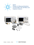
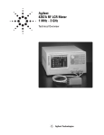
Keysight Technologies
Accessories Catalog for
Impedance Measurements
Catalog
i | Keysight | Accessories Catalog for Impedance Measurements - Catalog
Table of Contents
Introduction................................................................................................. 01
1. What are Keysight Technologies accessories?............................... 01
2. Types of accessories ...................................................................... 01
3. The Benefits of Keysight accessories............................................. 02
4. ISO 9000 quality management....................................................... 02
Tips for Selecting Appropriate Accessories...........................................03
1. Selection by measurement application.......................................... 03
2. Compatibility with measurement instruments...............................03
3. Frequency, DC bias, and operating temperature/humidity...........04
4. DUT (device under test) dimensions...............................................04
5. Open & short repeatability and proportional error........................04
6. Furnished accessories.....................................................................04
7. Terminal adapters............................................................................ 05
Accessories Catalog..................................................................................06
Applicable frequency ranges..............................................................06
Accessories organization.................................................................... 07
Up to 120 MHz (4-Terminal Pair)............................................................. 08
Lead Components.............................................................................09
16047A Test fixture......................................................................09
16047E Test fixture...................................................................... 10
SMD............................................................................................ 11
16034E Test fixture...................................................................... 11
16034G Test fixture..................................................................... 12
16034H Test fixture..................................................................... 13
16334A Tweezers contact test fixture........................................ 14
Other Components........................................................................... 15
16089A Large Kelvin clip leads................................................... 15
16089B Medium Kelvin clip leads............................................... 15
16089C Kelvin IC clip leads......................................................... 16
Port/Cable Extension....................................................................... 17
16048A Test leads....................................................................... 17
16048D Test leads....................................................................... 17
16048E Test leads........................................................................ 18
16048G Test leads....................................................................... 19
16048H Test leads....................................................................... 19
Probes................................................................................................. 20
42941A Impedance probe kit...................................................... 20
DC Bias Accessories......................................................................... 21
16065A 200 Vdc external voltage bias fixture........................... 21
16065C 40 Vdc external voltage bias adapter........................... 21
Material............................................................................................... 22
16451B Dielectric test fixture...................................................... 22
16452A Liquid dielectric test fixture........................................... 26
ii | Keysight | Accessories Catalog for Impedance Measurements - Catalog
Table of Contents continued
Up to 3 GHz (7 mm)................................................................................... 28
Lead Components............................................................................. 29
16092A Spring clip fixture........................................................... 29
SMD..................................................................................................... 30
16192A Parallel electrode SMD test fixture............................... 30
16194A High temperature component test fixture.................... 32
16196A Parallel electrode SMD test fixture...............................34
16196B Parallel electrode SMD test fixture............................... 37
16196C Parallel electrode SMD test fixture............................... 39
16196D Parallel electrode SMD test fixture............................... 41
16197A Bottom electrode SMD test fixture................................43
16198A Bottom electrode SMD test fixture...............................46
DC Bias Accessories.........................................................................48
16200B external DC bias adapter...............................................48
Material............................................................................................... 49
16453A Delectric material test fixture........................................ 49
16454A magnetic material test fixture....................................... 50
Other Accessories...................................................................................... 52
16190B Performance test kit.............................................................. 52
16380A Standard capacitor set.......................................................... 53
16380C Standard capacitor set..........................................................54
42030A Four-Terminal pair standard resistor set.............................. 55
42090A Open termination................................................................... 56
42091A Short termination................................................................... 56
Index............................................................................................................. 57
Keysight Web Resources..........................................................................60
Introduction
When a device under test (DUT) is measured, a test fixture must be used to connect the instrument to the DUT.
A test fixture is an interface specifically designed to connect the instrument and the contact tips of the DUT.
1. What are Keysight Technologies accessories?
Keysight Technologies offers a variety of accessories suitable for many applications. They are designed to
make measurements simple and reliable. For example, a mechanically and electrically precise test fixture is
required to measure the impedance of SMD components. For this measurement, Keysight offers dedicated
SMD fixtures for impedance measurement instruments that minimize the measurement errors. Also,
specially designed fixtures for other specific applications (such as DC bias test, dielectric material test, and
others.) are available. Keysight accessories facilitate a shorter time-to-market with increased confidence by
providing accurate and repeatable measurements.
2. Types of accessories
Keysight accessories can be divided into the following five categories:
Test fixtures
A test fixture is used to hold the electronic components or materials (physically and electrically) for the
measurements. Keysight offers various kinds of 4-Terminal Pair test fixtures and 7 mm test fixtures. Some of
them connect directly to the measurement instrument, while others require adapters.
Test leads
Test leads are used to extend the measurement ports from the UNKNOWN terminals of the instrument to
the DUT. Using a flexible test lead, a DUT that cannot be held with test fixtures can be measured regardless
of its size or shape. The test leads can also be used as cable extensions when the test sample is located
away from the measurement instrument.
Probes
Probes are helpful in measuring components which are already connected to PC boards or have one
terminal grounded.
Adapters
Adapters are used to adapt the dedicated circuits between the instrument and the test fixtures. The 42942A
is a terminal conversion adapter that can convert a 4-Terminal Pair configuration to a 7 mm configuration.
The 16065C is an external DC bias adapter that can apply DC bias to the DUT from an external DC bias
source.
Others
Also available are DC bias accessories and performance test equipment.
02 | Keysight | Accessories Catalog for Impedance Measurements - Catalog
Introduction continued
3. The Benefits of Keysight accessories
Each accessory is designed to ensure highly accurate measurements without degrading the performance of
the measurement instrument.
–– Minimum residual error preserves the accuracy of the measurement instruments.
–– Clearly defined error compensation allows easy calculation of error corrections.
–– Strict measurement specifications, such as test frequencies and signal levels provide safe and accurate
measurements.
This document introduces a group of Keysight accessories that are well suited for the following measurement instruments:
LCR meters
–– E4980A Precision LCR Meter, 20 Hz to 2 MHz
–– E4980AL Precision LCR Meter, 20 Hz to 300 kHz/500 kHz/1 MHz
–– E4982A LCR Meter, 1 MHz to 300 M/500 M/1G/ 3 GHz
Capacitance meters
–– E4981A Capacitance Meter
Impedance analyzers
–– E4990A Impedance Analyzer, 20 Hz to 10/20/30/50/120 MHz
–– E4991B Impedance Analyzer, 1 MHz to 500 MHz/1 GHz/3 GHz
Network analyzer
–– E5061B-3L3/3L4/3L5 LF-RF Network Analyzer, 5 Hz to 500 M/1.5 G/3 GHz
4. ISO 9000 quality management
ISO 9000 is a set of international standards for quality management and quality assurance. These standards
were developed with the goal of documenting and implementing effective quality systems within companies.
ISO standards are consistent with Keysight’s quality system; in fact, the standards within Keysight Technologies’ Quality Maturity System (QMS) exceed the intent of ISO 9000.
03 | Keysight | Accessories Catalog for Impedance Measurements - Catalog
Tips for Selecting Appropriate Accessories
The following topics comprise a helpful guideline for selecting an appropriate accessory
for the measurement instrument to be used.
1. Selection by measurement application
Keysight accessories can be used in a wide variety of measurement applications. These
applications range from basic measurements (such as impedance measurements for
discrete devices) to advanced measurements (such as measurement of resistivities or
dielectric constants.)
2. Compatibility with measurement instruments
Test fixtures/leads are compatible with the measurement instruments when they have
the same type of terminal configuration and useable measurement frequency range. The
measurement instruments described in this guide are divided into the following three
categories based on frequency.
Frequency
range
Up to 120 MHz
(Terminal configuration: 4-Terminal pair)
Measurement
E4980A/AL, E4981A, E4990A
instruments
Up to 3 GHz
(Terminal configuration: 7 mm)
E4982A, E4990A + 42942A*, E4991B,
E5061B-3L3/3L4/3L5 w/Opt. 005 + 16201A
* Option E4990A-120 is required.
04 | Keysight | Accessories Catalog for Impedance Measurements - Catalog
Tips for Selecting Appropriate Accessories continued
3. Frequency, DC bias, and operating temperature/humidity
each of the Keysight accessories has its own specific operating range. Any measurement
performed outside this range can increase residual errors and can cause problems. Be
sure that your measurement environment fits the accessory’s specific operating range.
In the case of humidity, Keysight’s accessories can operate at a relative humidity of 95%
or less at 40°C. (These same requirements apply to most LCR Meters and Impedance
Analyzers.) When the ambient temperature is not approximately 40°C, use an accessory
that has no condensation on its surface.
4. DUT (device under test) dimensions
The DUT can vary from chip components, axial/radial leads, or ICs to general electrical
materials. Select a test fixture/lead that is suitable for the shape and size of your
components or materials.
5. Open & short repeatability and proportional error
Since a test fixture induces an additional error when measuring, the total measurement
error is the sum of the measurement instrument’s measurement accuracy and the
fixture’s additional error. Generally, a test fixture’s additional error consists of three
terms: open repeatability, short repeatability and proportional error. Open and short
repeatability exhibit the error factors of the open and short residual impedances which
affect the measurements of extremely high and low impedances respectively. Proportional error exhibits the error factor, which is proportional to the value of the impedance
being measured. For more details on this subject, please refer to the Appendix.
6. Furnished accessories
Each test fixture is shipped with a manual and various other accessories needed for
measuring. For example, the 42941A impedance probe kit is furnished with a pin probe,
an adapter (BNC-SMA), 3 spare pins, a carrying case and an operation and service
manual.
05 | Keysight | Accessories Catalog for Impedance Measurements - Catalog
Tips for Selecting Appropriate Accessories continued
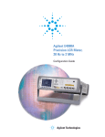
7. Terminal adapters
Terminal Adapters convert the instruments terminal configuration into a 7 mm terminal configuration. This means that instruments that do not have a 7 mm terminal connector can use test
fixtures with a 7 mm terminal connector. The 42942A converts a 4-Terminal Pair configuration
into a 7 mm terminal connector, which can only be used with the E4990A*.
42942A Terminal adapter
Applicable instrument: E4990A*
Frequency: 20 Hz to 120 MHz
Maximum voltage: ±42 V peak max. (AC +DC)
Operating temperature: 0to 40°C
Furnished accessories:
Dimensions (approx.):
190 (W) x 55 (H) x 140 (D) [mm]
Weight (approx.): 800 g
Description
P/N
Qty.
Carrying case
42942-60011
1
Operation and service manual
42942-90020
1
Description
P/N
Qty.
Open termination
04191-85302
1
Short termination
04191-85300
1
Load termination
04291-60043
1
* Option E4990A-120 is required
Options:
42942A-700: Add 7 mm open/short/load set
06 | Keysight | Accessories Catalog for Impedance Measurements - Catalog
Accessories Catalog
Applicable frequency ranges
DC
1k
1M
Frequency range
16047A
10 M
100 M
40 M
16034G/H
16065C
120 M
5
5
15 M
100 k
30 M
2M
120 M
120 M
40
50
2M
100
1M
16451B
16452A
30 M
20
30 M
16092A
500 M
16192A
2G
16194A
2G
16196A/B/C/D
3G
16197A
3G
16198A
3G
16200B
1M
16453A
16454A
3 G [Hz]
120 M
16034E
16048A/D
16048E
16048G/H
42941A
16065A
2 G [Hz]
13 M
16047E
16334A
16089A/B/C
1 G [Hz]
1M
1k
1G
1G
1G
: When 42942A is used.
07 | Keysight | Accessories Catalog for Impedance Measurements - Catalog
Accessories Catalog
Accessories organization
This document is organized by measurement frequency and DUT to enable quick
selection of an appropriate test fixture for a particular measurement application. The
following tables show the various categories in each primary group:
Up to 120 MHz (Terminal configuration: 4-Terminal pair)
Lead components
16047A/E
SMD components
16034E/G/H, 16334A
Other components
16089A/B/C
Port/Cable extension
16048A/D/E/G/H
DC bias accessories
16065A/C
Material
16451B, 16452A
Up to 3 GHz (Terminal configuration: 7 mm connector)
Lead components
16092A,16194A
SMD components
16092A, 16192A, 16194A, 16196A/B/C/D, 16197A, 16198A
DC bias accessories
16200B
Material
16453A, 16454A
Other accessories
Miscellaneous
16190B, 16380A/C, 42030A, 42090/1A
08 | Keysight | Accessories Catalog for Impedance Measurements - Catalog
Up to 120 MHz (4-Terminal Pair)
Test fixtures (4-Terminal pair) for impedance measurements up to 120 MHz
Frequency range
DC
1k
1M
10 M
16047A
100 M
13 M
16047E
120 M
16034E
40 M
16034G/H
16334A
5
16089A/B/C
5
120 M
15 M
100 k
16048A/D
30 M
16048E
2M
16048G/H
120 M
42941A
40
16065A
50
16065C
100
120 M
2M
1M
16451B
16452A
30 M
20
30 M
Applicable instrument
Frequency
range
Up to 120 MHz
(Terminal configuration: 4-Terminal pair)
Measurement
E4980A/AL, E4981A, E4990A
instruments
Up to 3 GHz
(Terminal configuration: 7 mm)
E4982A, E4990A + 42942A*, E4991B,
E5061B-3L3/3L4/3L5 w/Opt. 005 + 16201A
*Option E4990A-120 is required
09 | Keysight | Accessories Catalog for Impedance Measurements - Catalog
Up to 120 MHz (4-Terminal Pair): Lead Components
16047A Test fixture
Description: This test fixture is designed for impedance evaluation of axial/radial lead
type devices. The 16047A employs Kelvin contacts which realize a wide impedance
measurement range. The contact tip can be changed according to the device shape.
Applicable instruments: E4980A/AL, E4981A, E4990A
Frequency: DC to 13 MHz
Maximum voltage: ±42 V peak max. (AC+DC)
Operating temperature: 0 to 55°C
DUT size: See figure with module sizes.
Terminal connector: 4-Terminal pair, BNC
DUT connection: 4-Terminal
Dimensions (approx.):
124 (W) x 31 (H) x 62 (D) mm
Weight (approx.): 205 g
Additional error:
Type of error
Impedance
Proportional error
±5 x (f/10)2
f: [MHz]
16047A module sizes
Furnished accessories:
Description
P/N
Qty.
Module for axial lead
16061-70022
2
Module for radial lead mounting on fixture
16061-70021
2
Module for short radial lead
16047-65001
2
Operating note
16047-90011
1
Each module size for the 16047A is shown above.
Option:
16047A-701: Add Shorting plate
P/N 16047-00640
Compensation and measurement: Select one of these modules suitable for the DUT’s
shape. Open and short compensations are recommended before measurement. Short
compensation is performed by shorting the contacts of the test fixture with a shorting
plate. After performing open and short compensations, the DUT is connected to the test
fixture.
P/N 16047-00640
Material:
Brass (Ni-dipped)
Thickness:
1.0 mm
Residual impedance:
20nH, 1mΩ
Shorting plate
10 | Keysight | Accessories Catalog for Impedance Measurements - Catalog
Up to 120 MHz (4-Terminal Pair): Lead Components continued
16047E Test fixture
Terminal connector: 4-Terminal Pair, BNC
DUT connection: 2-Terminal
Dimensions (approx.):
135 (W) x 40 (H) x 65 (D) [mm]
Weight (approx.): 200 g
Additional error:
Proportional error
f ≤ 15 MHz
0.2 x (f/10)2[%]
9.3 mm
±42 V Peak max output
2 mm
Top view
Proportional error
f > 15 MHz
4 x (f/100)[%]
Open repeatability
2 n+10 µ x (f/100) [S]
Short repeatability
2 m+600 m x (f/100) [Ω]
f: [MHz]
14 mm
10 mm
Impedance
Guard terminal
5.3 mm
Type of error
Description: This test fixture is designed for impedance evaluation of lead type devices
up to 120 MHz. A guard terminal is available for three terminal devices and a shorting
plate comes secured on this fixture.
Applicable instruments: E4980A/AL, E4981A, E4990A, E5061B-3L3/3L4/3L5
with Opt. 005
Frequency: DC to 120 MHz
Maximum voltage: ±42 V peak max.(AC+DC)
Operating temperature: –20 to 75°C
DUT size: See figure below with 16047E’s electrode size.
1.6 mm
62 mm
Side view
Shorting plate
(furnished)
Furnished accessories:
Description
P/N
Qty.
Angle (right-side)
16047-01221
1
Angle (left-side)
16047-01222
1
Screws
0515-1229
4
Shorting plate
16047-00621
1
Operating and service manual
16047-90040
1
Compensation and measurement: Open and short compensations are recommended
before measurement. Short compensation is performed by shorting the contacts of the
test fixture with a shorting plate. After performing open and short compensations, the
DUT is connected to the test fixture. The following figures show how compensation and
measurement are performed.
Test fixture overview
Connecting a shorting plate
Measuring 3-Terminal device
11 | Keysight | Accessories Catalog for Impedance Measurements - Catalog
Up to 120 MHz (4-Terminal Pair): SMD
16034E Test fixture
Description: This test fixture is designed for impedance evaluations of SMD. The
minimum SMD size that this fixture is adapted to evaluate is 1.6(L) x 0.8(W) [mm].
Applicable instruments: E4980A/AL, E4981A, E4990A, E5061B-3L3/3L4/3L5
with Opt. 005
Frequency: DC to 40 MHz
Maximum voltage: ±42 V peak max. (AC+DC)
Operating temperature: 0°C to 55°C
DUT size: See figure below
Terminal connector: 4-Terminal Pair, BNC
DUT connection: 2-Terminal
Dimensions (approx.):
128 (W) x 60 (H) x 71 (D) [mm]
Weight (approx.): 270 g
Additional error:
Type of error
Proportional error
f: [MHz]
Impedance
±1.5 x
(f/10)2
Furnished accessories:
Description
P/N
Qty.
Operating manual
16034-90041
1
Compensation and measurement: Open and short compensations are recommended
before measurement. Open compensation is performed by separating the high and low
electrodes from each other. The separation should be equivalent in size to the DUT’s
width. Short compensation is performed by contacting the high and low electrodes
together. After performing open and short compensations, the DUT is inserted into
the test fixture. The following figures show how compensation and measurement are
performed.
Open compensation
Short compensation
Inserting a DUT
Electrode dimensions
12 | Keysight | Accessories Catalog for Impedance Measurements - Catalog
Up to 120 MHz (4-Terminal Pair): SMD continued
16034G Test fixture
Description: This test fixture is designed for impedance evaluations of SMD. The
minimum SMD size that this fixture is adapted to evaluate is 0.6 (L) x 0.3 (W) [mm].
Applicable instruments: E4980A/AL, E4981A, E4990A, E5061B-3L3/3L4/3L5
with Opt. 005
Frequency: DC to 120 MHz
Maximum voltage: ±42 V peak max. (AC+DC)
Operating temperature: 0 to 55°C
DUT size: See figure below
Terminal connector: 4-Terminal Pair, BNC
DUT connection: 2-Terminal
Dimensions (approx.):
120 (W) x 50 (H) x 70 (D) [mm]
Weight (approx.): 200 g
Additional error:
Type of error
Impedance
Proportional error
0.5 x (f/10)2[%]
Open repeatability
5 + 500 x (f/10) [nS]
Short repeatablity
f: [MHz]
10 + 13 x (f/10) [mΩ]
Furnished accessories:
Description
P/N
Qty.
Case for 100 Ω SMD resistance
1540-0692
1
100 Ω chip resistor
0699-2488
10
Operating manual
16034-90011
1
Compensation and measurement: Open and short compensations are recommended
before measurement. When measuring above 3 MHz, load compensation is also
recommended. Open compensation is performed by separating the high and the low
electrodes from each other. The separation size should be equivalent to the DUT’s
width. Short compensation is performed placing the high and low electrodes in contact
together. Load compensation is performed by using the furnished 100 Ω SMD chip
resistor. After performing open, short and load compensations, the DUT is inserted into
the test fixture. The following figures show how compensation and measurement are
performed.
E4980A with 16034G
Open compensation
Short compensation
DUT measurement
Dimensions
13 | Keysight | Accessories Catalog for Impedance Measurements - Catalog
Up to 120 MHz (4-Terminal Pair): SMD continued
16034H Test fixture
Terminal connector: 4-Terminal Pair, BNC
DUT connection: 2-Terminal
Dimensions (approx.):
120 (W) x 50 (H) x 70 (D) [mm]
Weight (approx.): 200 g
Additional error:
Description: This test fixture is designed for impedance evaluations of array-type SMD.
The minimum SMD size that this fixture is adapted to evaluate is 1.6(L) x 0.8(W) [mm].
Since the tip of the measurement electrodes are very thin and the device holder is
extremely flat, the device can be shifted and the measurement electrodes can contact
the each element of the array-type component.
Applicable instruments: E4980A/AL, E4981A, E4990A, E5061B-3L3/3L4/3L5
with Opt. 005
Frequency: DC to 120 MHz
Maximum voltage: ±42 V peak max. (AC+DC)
Operating temperature: 0 to 55°C
DUT size: See figure below
Type of error
Impedance
Proportional error
0.5 x (f/10)2[%]
Open repeatability
5 + 500 x (f/10) [nS]
Description
P/N
Qty.
10 + 13 x (f/10) [mΩ]
Case for 100 Ω SMD resistance
1540-0692
1
100 Ω chip resistor
0699-2488
10
Operating manual
16034-90012
1
Short repeatablity
f: [MHz]
Furnished accessories:
Compensation and measurement: Open and short compensations are recommended
before measurement. When measuring above 3 MHz, load compensation is also
recommended. Open compensation is performed by separating the high and the low
electrodes from each other. The separation should be equivalent in size to the DUT’s
width. Short compensation is performed by placing the high and low electrodes in
contact together. Load compensation is performed by using the furnished 100 Ω SMD
chip resistor. After performing open, short and load compensations, the DUT is inserted
into the test fixture. Refer to the 16034G figures to see how compensation and measurement are performed.
Electrode dimensions
14 | Keysight | Accessories Catalog for Impedance Measurements - Catalog
Up to 120 MHz (4-Terminal Pair): SMD continued
16334A Tweezers contact test
fixture
Description: This test fixture is designed for impedance evaluations of SMD. The
minimum SMD size that this fixture is adapted to evaluate is 1.6(L) x 0.8(W) [mm]. The
tweezers’ contacts on this fixture makes it easy to hold the DUT.
Applicable instruments: E4980A/AL, E4981A, E4990A
Frequency: 5 Hz to 15 MHz
Maximum voltage: ±42 V peak max. (AC+DC)
Operating temperature: 0 to 55°C
DUT size: ≤10 mm (width)
See figure below
Terminal connector: 4-Terminal Pair, BNC
DUT connection: 2-Terminal
Cable length (approx.): 1 m (from BNC
connectors to the top of tweezers)
Weight (approx.): 290 g
Additional error:
Type of error
Impedance
Proportional error
±2 x (f/10)2
f: [MHz]
Furnished accessories:
Description
P/N
Qty.
Compensation block
16334-60001
1
Operating note
16334-90000
1
Compensation and measurement: Open and short compensations are recommended
before measurement. Open and short compensations are performed by using the
furnished compensation block. After performing open and short compensations, the
DUT is sandwiched by the tweezers’ contacts and is measured.
15 | Keysight | Accessories Catalog for Impedance Measurements - Catalog
Up to 120 MHz (4-Terminal Pair): Other Components
16089A Large Kelvin clip leads
Description: This test fixture makes it possible to measure odd-shaped components
that cannot be measured with conventional fixtures. It is equipped with two insulated
Kelvin clips.
Applicable instruments: E4980A/AL, E4981A, E4990A
Frequency: 5 Hz to 100 kHz
Maximum voltage: ±42 V peak max. (AC+DC)
Operating temperature: 0 to 55°C
DUT size:
See figure below
Terminal connector:
4-Terminal Pair, BNC
DUT connection: 4-Terminal
Cable length (approx.):
0.94 m (from connector to clip's tip)
Weight (approx.): 300 g
Additional error: The additional error is
negligible when compared to the instrument's accuracy.
Furnished accessories:
Description
P/N
Qty.
Operating and service manual
16089-90020
1
Compensation and measurement: Open and short compensations are recommended
before measurement. For open compensation, do not connect the Kelvin clips to anything. Short compensation is performed by holding a shorting plate with the Kelvin clips.
After performing open and short compensations, the DUT is held with the Kelvin clips.
16089B Medium Kelvin clip leads
Description: This test fixture makes it possible to measure odd-shaped components
that cannot be measured with conventional fixtures. It is equipped with two insulated
Kelvin clips.
Applicable instruments: E4980A/AL, E4981A, E4990A
Frequency: 5 Hz to 100 kHz
Maximum voltage: ±42 V peak max. (AC+DC)
Operating temperature: 0 to 55°C
DUT size: See figure below
Terminal connector: 4-Terminal Pair, BNC
DUT connection: 4-Terminal
Cable length (approx.):
0.94 m (from connector to clip's tip)
Weight (approx.): 300 g
Additional error: The additional error is negligible when compared to the instrument's
Furnished accessories:
accuracy.
Description
Operating and service manual
P/N
Qty.
16089-90020
1
Compensation and measurement: Open and short compensations are recommended
before measurement. For open compensation, do not connect the Kelvin clips to anything.
Short compensation is performed by connecting the Kelvin clips together. After
performing open and short compensations, the DUT is held with the Kelvin clips.
16 | Keysight | Accessories Catalog for Impedance Measurements - Catalog
Up to 120 MHz (4-Terminal Pair): Other Components continued
16089C Kelvin IC clip leads
Description: This test fixture makes it possible to measure odd-shaped components that
cannot be measured with conventional fixtures. It is equipped with two insulated Kelvin
clips.
Applicable instruments: E4980A/AL, E4981A, E4990A
Frequency: 5 Hz to 100 kHz
Maximum voltage: ±42 V peak max. (AC+DC)
Operating temperature: 0 to 55°C
DUT size:
See figure below
Terminal connector: 4-Terminal Pair, BNC
DUT connection: 4-Terminal
Cable length (approx.):
1.3 m (from connector to clip's tip)
Weight (approx.): 300 g
Additional error: The additional error
is negligible when compared to the
instrument's accuracy.
Furnished accessories:
Description
P/N
Qty.
Operating and service manual
16089-90020
1
Compensation and measurement: Open and short compensations are recommended
before measurement. For open compensation, do not connect the Kelvin clips to
anything. Short compensation is performed by connecting the Kelvin clips together.
After performing open and short compensations, the DUT is held with the Kelvin clips.
17 | Keysight | Accessories Catalog for Impedance Measurements - Catalog
Up to 120 MHz (4-Terminal Pair): Port/Cable Extension
16048A Test leads
Description: The test leads extend the measurement port with a 4-Terminal Pair
configuration. It is provided with a BNC female connector board to allow the attachment
of user-fabricated test fixtures.
Applicable instruments: E4980A/AL, E4981A
Frequency: DC to 30 MHz
Maximum voltage: ±42 V peak max. (AC+DC)
Operating temperature: 0 to 55°C
Furnished accessories:
Terminal connector: 4-Terminal Pair, BNC
Cable length (approx.):
0.94 m (from connector to cable tip)
Cable tip: BNC (male)
Weight (approx.): 315 g
Additional error: For detailed information,
refer to the measurement instrument's
specifications.
Description
P/N
Qty.
Terminal board with BNC(f)x4
16032-60071
1
Operating manual
16089-90001
1
Compensation and measurement: Cable length compensation is recommended before
measurement. Set the instrument's cable length compensation function to 1 m.
16048D Test leads
Description: The test leads extend the measurement port with a 4-Terminal Pair
configuration. It is provided with a BNC female connector board to allow the attachment of user-fabricated test fixtures.
Applicable instruments: E4980A/AL, E4981A
Frequency: DC to 30 MHz
Maximum voltage: ±42 V peak max. (AC+DC)
Operating temperature: 0 to 55°C
Furnished accessories:
Terminal connector: 4-Terminal Pair, BNC
Cable length (approx.):
1.89 m (from connector to cable tip)
Cable tip: BNC (male)
Weight (approx.): 460 g
Additional error: For detailed information,
refer to the measurement instrument’s
specifications.
Description
P/N
Qty.
Terminal board with BNC(f)x4
16032-60071
1
Operating manual
16048-90031
1
Compensation and measurement: Cable length compensation is recommended before
measurement. Set the instrument’s cable length compensation function to 2 m.
18 | Keysight | Accessories Catalog for Impedance Measurements - Catalog
Up to 120 MHz (4-Terminal Pair): Port/Cable Extension continued
16048E Test leads
Description: The test leads extend the measurement port with a 4-Terminal Pair
configuration. It is provided with a BNC female connector board to allow the attachment
of user-fabricated test fixtures.
Applicable instruments: E4980A/AL
Frequency: DC to 2 MHz
Maximum voltage: ±42 V peak max. (AC+DC)
Operating temperature: 0 to 55°C
Furnished accessories:
Terminal connector: 4-Terminal Pair, BNC
Cable length (approx.): 3.8 m (from
connector to cable tip)
Cable tip: BNC (male)
Weight (approx.): 690 g
Additional Error: For detailed information,
refer to the measurement instrument’s
specifications.
Description
P/N
Qty.
Terminal board with BNC(f)x4
16032-60071
1
Operating manual
16048-90041
1
Compensation and measurement: Cable length compensation is recommended before
measurement. Set the instrument’s cable length compensation function to 4 m.
19 | Keysight | Accessories Catalog for Impedance Measurements - Catalog
Up to 120 MHz (4-Terminal Pair): Port/Cable Extension continued
16048G Test leads
Description: The test leads extend the measurement port with a 4-Terminal Pair
configuration. It is provided with a BNC male connector board to allow the attachment
of user-fabricated test fixtures.
Applicable instrument: E4990A
Frequency: DC to 120 MHz
Maximum voltage: ±42 V peak max. (AC+DC)
Operating temperature: –20 to 150°C
Furnished accessories:
Terminal connector: 4-Terminal pair, BNC
Cable length (approx.): 1 m
Cable tip: BNC (female)
Weight (approx.): 460 g
Additional error: For detailed information,
refer to the operation manual or the
specifications of E4990A.
Description
P/N
Qty.
Mounting plate
NA
1
Operating and service manual
16048-90050
1
Options:
16048G-001: Add BNC Bracket* (P/N 16048-60003)
* Here the BNC Bracket refers to the terminal board with four BNC (m)connectors.
Compensation and measurement: Adapter setup is recommended before measurement.
In the adapter setup menu, select 4TP 1M. Then use the 100 Ω resistor furnished with
the E4990A to perform phase compensation and load data measurement.
Test fixture overview
16048H Test leads
Description: The test leads extend the measurement port with a 4-Terminal Pair
configuration. It is provided with a BNC male connector board to allow the attachment
of user-fabricated test fixtures.
Applicable instrument: E4990A
Frequency: DC to 120 MHz
Maximum voltage: ±42 V peak max. (AC+DC)
Operating temperature: –20 to 150°C
Furnished accessories:
Terminal connector: 4-Terminal pair, BNC
Cable length (approx.): 2 m
Cable tip: BNC (female)
Weight (approx.): 690 g
Additional error: For detailed information,
refer to the operation manual or the
specifications of E4990A.
Description
P/N
Qty.
Mounting plate
NA
1
Operating and service manual
16048-90050
Options:
16048H-001: Add BNC Bracket* (P/N 16048-60003)
1
* Here the BNC Bracket refers to the terminal board with four BNC (m) connectors.
Compensation and measurement: Adapter setup is recommended before measurement.
In the adapter setup menu, select 4TP 2M. Then use the 100 Ω resistor furnished with
the E4990A to perform phase compensation and load data measurement.
20 | Keysight | Accessories Catalog for Impedance Measurements - Catalog
Up to 120 MHz (4-Terminal Pair): Probes
42941A Impedance probe kit
Terminal connector: 4-Terminal pair, BNC
Cable length (approx.): 1.5 m
Weight (approx.): 2400 g
Basic measurement accuracy: ±1%
For detailed information, refer to the
operation manual or the specifications of
E4990A-120.
E4990A-120 with 42941A
Description: This impedance probe kit is designed for use with the E4990A-120. It
provides the capability to perform in-circuit measurements (printed circuit patterns,
the input/output impedance of circuits, etc.) with better accuracy and wider impedance
coverage from 20 Hz to 120 MHz. DUTs can be connected by either using the pin probe,
the clip lead (alligator clip adapter) or the BNC adapter. All probe adapter can be used
from 20 Hz to 120 MHz. The pin probe is best for in-circuit, board-mounted components, The clip lead is for components too large for the pin probe. The BNC adapter is
used to connect circuits or networks equipped with BNC connectors.
Applicable instrument: E4990A-120
Frequency: 20 Hz to 120 MHz
Maximum voltage: ±42 V peak max. (AC+DC)
Operating temperature: –20 to +75°C (probe only)
Furnished accessories:
Description
P/N
Qty.
Pin probe
42941-60002
1
Adapter BNC-SMA
1250-2375
1
Spare pin Set (3 ea.)
42941-60004
1
3.5 mm SHORT
1250-2840
1
3.5 mm LOAD
0955-1105
1
Clip lead
8121-0003
1
Ground lead
04193-61679
1
Carrying case
42941-60011
1
Operating and service manual
42941-90010
1
Compensation and measurement: Adapter setup and compensation is required before
measurement. In the Adapter setup menu, select PROBE 42941A. Use the furnished
3.5 mm short and load standards. The open condition can be created by not connecting
the probe to anything. Perform phase compensation, short and load data measurements. For compensation, open and short compensation is recommended. Short
compensation is performed by shorting the probe. To short the probe it is recommended
to use a shorting device with gold-plated surfacing (which provides stable contact
resistance).
Open compensation
In-circuit measurement
Short compensation
21 | Keysight | Accessories Catalog for Impedance Measurements - Catalog
Up to 120 MHz (4-Terminal Pair): DC Bias Accessories
16065A 200 Vdc external voltage
bias fixture
Terminal connector: 4-Terminal Pair, BNC
DUT connection: 4-Terminal
External bias input connector: High Voltage BNC(f)
Dimensions (approx.): 180 (W) x 120 (H) x 200 (D) [mm]
Cable length (approx.): 40 cm
Weight (approx.): 1500 g
High Voltage BNC(f) connector for external bias input
BNC(f) connector for voltage monitor output
Description: This test fixture makes it possible to measure a DUT with up to ±200
V DC bias. The same modules of 16047A can be used to allow measurements of
axial/radial lead components.
Applicable instruments: E4980A/AL, E4981A, E4990A
Frequency: 50 Hz to 2 MHz
Maximum DC bias: ±200 V DC max. /15 V peak AC max.
Blocking capacitor of 5.6 µF is connected in with the Hc terminal.
Operating temperature: 0 to 55°C
DUT Size: See the 16047A figure with module sizes.
Furnished accessories:
Description
P/N
Qty.
Module for axial lead
16061-70022
1
Module for radial lead mounting on fixture
16061-70021
1
Module for short radial lead
16047-65001
1
Shorting bar
16047-00640
1
Operating and service manual
16065-90011
1
Compensation and measurement: Open, short and load compensations are recommended before measurement. Short compensation is performed by shorting the
contacts of the test fixture with a shorting plate as described for the 16047A. Load
compensation is performed by inserting a known standard device. After performing
open, short and load compensations, the DUT is connected to the test fixture.
LCR meter with 16065A
16065C 40 Vdc external
voltage bias adapter
Terminal connector: 4-Terminal Pair, BNC
External bias input connector: BNC(f)
Dimensions (approx.): 160 (W) x 50 (H) x 150 (D) [mm]
Cable length (approx.): 210 mm
Weight (approx.): 450 g
Description: This adapter is designed to operate specifically with the E4981A
and the E4980AL. By connecting an external DC voltage source to this adapter, a
bias voltage of up to ±40 V can be supplied to a DUT. The DUT can be inserted by
connecting any direct attachment 4-Terminal Pair test fixture to the adapter.
Applicable instruments: E4981A and E4980AL
Frequency: 100 Hz to 1 MHz
Maximum DC bias: ±42 V peak max. (AC+DC)
Blocking Capacitor of 100 µF is connected in series with the Hc terminal.
Operating temperature: 0 to 55°C
Applicable fixtures: 16034E/G/H, 16047A/E, 16048A/D, 16089A/B/C
Furnished accessories:
Description
P/N
Qty.
Operating and service manual
16065-90020
1
Compensation and measurement: Open and short compensations are recommended before measurement. Short compensation is performed by shorting
the contacts of the test fixture that is in use. After performing open and short
compensations, the DUT is connected to the test fixture.
LCR meter with 16065C
22 | Keysight | Accessories Catalog for Impedance Measurements - Catalog
Up to 120 MHz (4-Terminal Pair): Material
16451B Dielectric test fixture
Description: The 16451B is used to evaluate the dielectric constant of solid
dielectric materials accurately, and complies with ASTM D150. The 16451B
employs the parallel plate method, which sandwiches the material between two
electrodes to form a capacitor. LCR meter or an Impedance Analyzer is then
used to measure the capacitance created from the fixture. A measurement block
diagram of the parallel plate method is shown below:
Terminal connector: 4-Terminal pair, BNC
Dimension (approx.): See page 26
Cable length (approx.):
0.8 m(from connector to electrodes)
Weight (approx.): 3700 g
Measurement accuracy
ε'r accuracy
(
∆ε' r m
ε' r m
Parallel plate method
)
Notice the stray capacitance, which is formed on the test material as shown in
the figure above. The guard electrode helps to eliminate the stray capacitance
at the edge of the electrode.
tan δ < 0.1:
AZ + 0.04 f 2 ε'rm ε0
d
2
t
π
2
+
100 (ε'rm – 1)
(ε'rm – t )
0.01
[%]
ε* Loss Tangent Accuracy (∆ tan δ)
tan δ < 0.1 : Ad + Ea + Eb
Ea = 0.005 + 0.0004 f
2
ε'r m ε0
Basic measurement accuracy (including the E4990A):
Typical Permittivity (εr�) Measurement Accuracy:
π
d
2
t
2
∆ε'r m
Eb = tan δ
100 ε'r m
(supplemental performance characteristics):
f: measured frequency [Hz] f ≤ 30 MHz
ε�rm: measured permittivity
tan δ: measured dissipation factor
ε0 : permittivity of air 8.854 × 10⁻¹²[F/m]
d: diameter of electrode {A,B}
t: thickness of material [mm]
Az: Impedance measurement error of instrument
Ad: D measurement error of instrument
Typical Loss Tangent (tan δ) Measurement Accuracy:
The material is assumed to be ideally flat.
The above equation is applicable for electrodes A
and B when using the contacting electrode method.
E4990A Measurement settings;
1. Osc level : 500 mV
2. Meas Time: 5 Precise
3. Adapter setup : 1 m
4. Compensation : Open, short and load
E4990A with 16451B
23 | Keysight | Accessories Catalog for Impedance Measurements - Catalog
Up to 120 MHz (4-Terminal Pair): Material continued
16451B Dielectric test fixture continued
Applicable instruments: E4980A/AL, E4981A, E4990A
Frequency: DC to 30 MHz
Maximum voltage: ±42 V peak max. (AC+DC)
Operating temperature: 0 to 55°C
Material size:
Electrodes for contacting electrode method (Rigid Metal
Electrode)
Material size for electrode-A
Material size for electrode-B
Equipped with Electrodes A and B for flat and smooth materials.
Electrode type
Diameter of MUT
Thickness of MUT
Diameter of electrode
Max. frequency
A
40 mm ~ 56 mm
t ≤ 10 mm
38 mm
30 MHz
B
10 mm ~ 56 mm
t ≤ 10 mm
5 mm
30 MHz
Electrodes for contacting electrode method (Thin Film
Electrode)
Material size for electrode-C
Material size for electrode-D
Equipped with Electrodes C and D for rough or extremely thin materials.
Electrode type
Diameter of MUT
Thickness of MUT
Diameter of electrode
Max. frequency
C
56 mm
t ≤ 10 mm
5 ~ 50 mm
30 MHz
D
20 mm ~ 56 mm
t ≤ 10 mm
5 ~ 14 mm
30 MHz
* diameter of applied thin film electrode
24 | Keysight | Accessories Catalog for Impedance Measurements - Catalog
Up to 120 MHz (4-Terminal Pair): Material continued
16451B Dielectric test fixture continued
Furnished accessories:
Description
P/N
Qty.
Test Fixture including Electrode-A, unguarded electrode and cover
N/A
1
A
Electrode-B and cover
16451-60013
1
B
Electrode-C and cover
16451-60012
1
C
Electrode-D and cover
16451-60014
1
D
Attachment for error compensation and cover
16451-60021
1
E
Hex key (for replacing electrodes)
5188-4452
1
F
Carrying Case
16451-60001
1
G
Dimensions of unguarded electrode
Dimensions of fixture assembly
25 | Keysight | Accessories Catalog for Impedance Measurements - Catalog
Up to 120 MHz (4-Terminal Pair): Material continued
16451B Dielectric test fixture continued
Compensation and measurement: There are three measurement methods for the
16451B. They are the Contacting Electrode Method (used with 16451B’s rigid metal
electrode, without any electrodes on the material under test), the Contacting Electrode
Method (used with thin film electrodes made on the material under test), and the NonContacting Electrode (Air Gap method). Select the suitable measurement method and
the suitable electrode for the material under test according to the following table.
Summary of measurement method
Measurement
method
Contacting electrode method (used with
rigid metal electrode)
Accuracy
Low
Operation
Simple
Applicable
materials
Thick, solid and smooth materials
Contacting electrode method (used
with thin film electrode)
> High
> Complex
Materials on which thin film can
be applied without changing its
characteristics
Open and short compensations are recommended in combination with the cable length
compensation before measurement. When measuring above 5 MHz with the E4990A,
load compensation is also recommended. First, set the instrument’s cable length
compensation function to 1 m. Then, open and short compensation is performed by
using the furnished electrode attachment. Load compensation is performed, by preparing a working standard. After performing open, short and load compensations, the MUT
is sandwiched by the parallel electrodes and the capacitance is measured. Relative
permittivity is calculated from the measured capacitance in the following manner:
εr�=
εr� :
Cp :
o :
ta :
d :
t a × Cp
d2×ε
π × (—)
o
2
Relative permittivity
Capacitance (measurement data)
8.854 × 10 –12 [F/m]
Average thickness of test material
Diameter of guarded electrode
Non-contacting electrode method
Thick, and soft materials Rough
materials also
26 | Keysight | Accessories Catalog for Impedance Measurements - Catalog
Up to 120 MHz (4-Terminal Pair): Material continued
16452A Liquid dielectric test fixture
Description: This test fixture provides accurate dielectric constant and impedance
measurements of liquid materials. The 16452A employs the parallel plate method,
which sandwiches the liquid material between two electrodes to form a capacitor.
A LCR meter or an impedance analyzer is then used to measure the capacitance
created from the fixture.
Applicable instruments: E4980A/AL, E4990A
Frequency: 20 Hz to 30 MHz
Operating temperature: –20 to 125°C
Maximum voltage: 30 Vrms
Material capacity: Required sample liquid capacity depends on the gap of the electrodes.
Terminal connector: 4-Terminal Pair, SMA
Dimensions (approx.): 8
5 (H) x 85 (W) x 37 (D) [mm]
Weight (approx.): 1400 g
Measurement accuracy: A + B + C [%]
Error A [%]
Gap of electrodes
0.3 mm
0.5 mm
1 mm
Air capacitance
34.9 pF ±25%
21.2 pF ±15%
10.9 pF ±10% 5.5 pF ±10%
Sample liquid capacity
3.4 ml
3.8 ml
4.8 ml
Applicable frequency
20 Hz – 30 MHz
(A)
(H)
2 mm
6.8 ml
(I)
(B)
(C)
(F)
(G)
(D)
Error B [%]
Error C [%] = Measurement Error of Instrument
(E)
Furnished accessories:
Description
Shorting plate
O-ring for liquid outlet
Spacer (1.3 mm thickness)
Spacer (1.5 mm thickness)
Spacer (2.0 mm thickness)
Spacer (3.0 mm thickness)
Lid of liquid outlet
SMA-BNC adapter
Waterproof cap for BNC connector
Carrying case
Operation and service manual
Angle iron of stand body for fixture stand
Screw of stand body or fixture stand
Screw for fixture stand
Stand foot
Electrode (high and low)
P/N
16092-08010
0905-1277
16452-00601
16452-00602
16452-00603
16452-00604
16452-24002
1250-1200
1252-5821
16452-60111
16452-90020
16452-01201
0515-0914
0515-0914
16452-00611
NA
Qty.
1
1
1
1
1
1
1
4
4
1
1
2
4
4
1
2
E
D
F
F
F
F
G
H
I
–
–
–
C
–
–
A.B
Requires the following interface cables to connect to a measurement instrument. Select
accordingly to the required temperature conditions.
LCR meter with 16452A
Temperature
Model# or P/N
Cable length (approx.)
0 to 55°C
16048A
0.94 m
–20 to 150°C
16048G* for E4990A only
1m
–20 to 150°C
16048H* for E4990A only
2m
* Four BNC(m) to BNC(m) adapters (P/N 1250-0216) are needed to connect
the 16048G/H and 16452A.
27 | Keysight | Accessories Catalog for Impedance Measurements - Catalog
Up to 120 MHz (4-Terminal Pair): Material continued
16452A Liquid dielectric test fixture continued
Compensation and measurement: Short compensation is recommended
in combination with the cable length compensation before measurement.
First, set the instrument’s cable length compensation function to 1 m. Then,
short compensation is performed by using the furnished shorting plate. Open
compensation is not performed, but its values are used in the dielectric constant
equation as shown below:
Cp
1
__ – j _______
)
Co ω CoRp
Correction coefficient
Relative dielectric constant
Liquid capacitance (measurement data)
Air capacitance (measurement data) or open compensation data
Equivalent parallel resistance (measurement data)
Angular frequency (ω = 2πf)
εr = α (
Fixture materials
Electrode: Ni plated Cobal
(Fe 54%, Co 17%, Ni 29%)
Insulator: Alumina (Al2O3)
O-ring: Viton (Fluro rubber)
Test fixture overview
α :
εr :
Cp :
Co :
Rp :
ω :
The following figures below show how compensation and measurement is
performed.
Short compensation
Pouring the liquid into the fixture
Note: The 16452A is not capable of measuring salt or ionic solutions or other
liquids with bulk conductivity due to the electrode polarization phenomenon.
Keysight is not responsible for any damage (e.g., corrosion, smear) to the 16452A
caused by the reaction between the liquid under test and the 16452A.
Method of connection
28 | Keysight | Accessories Catalog for Impedance Measurements - Catalog
Up to 3 GHz (7 mm)
Frequency range
DC
16092A
16192A
16193A
16194A
16196A/B/C/D
16197A
16198A
16200B
16453A
16454A
1k
1M
10 M
100 M
1 G [Hz]
3G [Hz]
500 M
2G
2G
2G
3G
3G
3G
1M
1M
1G
1G
1G
1k
: When 42942A is used.
Applicable instrument
Frequency
range
2 G [Hz]
Up to 120 MHz
(Terminal configuration: 4-Terminal Pair)
Measurement
E4980A/AL, E4981A, E4990A
instruments
Up to 3 GHz
(Terminal configuration: 7 mm)
E4982A, E4990A + 42942A*, E4991B,
E5061B-3L3/3L4/3L5 w/Opt. 005 + 16201A
* Option E4990A-120 is required
29 | Keysight | Accessories Catalog for Impedance Measurements - Catalog
Up to 3 GHz (7 mm): Lead Components
16092A Spring clip fixture
Description: This test fixture is designed for impedance evaluation of both lead
and SMD. It is furnished with two modules that can be readily screwed onto the
plate to measure either lead or SMD.
Applicable instrument: E4982A, E4990A + 42942A*, E4991B,
E5061B-3L3/3L4/3L5 with Opt. 005 + 16201A
* Option E4990A-120 is required
Terminal connector: 7 mm
DUT connection: 2-Terminal
Electrical length: 3.4 mm
Dimensions (approx.): 150 (W) x 70 (H) x 80 (D) [mm]
Weight (approx.): 180 g
Additional error: See figure below
Frequency: DC to 500 MHz
Maximum voltage: ±42 V peak max. (AC+DC)
Operating temperature: 0 to 55°C
DUT size: See figure below
Furnished accessories:
Inserting the SMD
Inserting the leaded component
Description
P/N
Qty.
Shorting plate
16092-08010
1
Operating note
16092-90010
1
Compensation and measurement: Open and short compensations are
recommended in combination with the electrical length compensation before
measurement. The fixture’s electrical length must be entered into the electrical
length compensation function of the measurement instrument first. When using
the SMD module, open compensation is performed by separating the high and
the low electrodes from each other. The separation should be equivalent in size
to the DUT’s width. Short compensation is performed by usinf the furnished
shorting plate. When using the lead component module, open compensation
is performed by not having the module-electrodes be connected to anything.
Short compensation is performed by using the furnished shorting plate. After
performing open and short compensations in combination with the electrical
length compensation, the DUT is inserted into the test fixture.
30 | Keysight | Accessories Catalog for Impedance Measurements - Catalog
Up to 3 GHz (7 mm): SMD
16192A Parallel electrode SMD
test fixture
Description: This test fixture is designed for impedance evaluations of parallel electrode
SMD. The minimum SMD size that this fixture is adapted to evaluate is 1 (L) [mm].
Applicable instrument: E4982A, E4990A + 42942A*, E4991B, E5061B-3L3/3L4/3L5
with Opt. 005 + 16201A
*Option E4990A-120 is required
Frequency: DC to 2 GHz
Maximum voltage: ±42 V peak max. (AC+DC)
Operating temperature: –55 to +85°C
DUT size: 1 mm to 20 mm (length)
Terminal connector: 7 mm
DUT connection: 2-Terminal
Electrical length: 11 mm
Dimensions (approx.):
150 (W) x 70 (H) x 90 (D) [mm]
Weight (approx.): 400 g
Additional error:
Type of error
Furnished accessories:
Impedance
f2
Proportional error
1.5 x
Open repeatability
2 + 30 x f [ µS]
Short repeatability
30 + 250 x f [mΩ]
f: [GHz]
[%]
Description
P/N
Qty.
Option
Operation and service manual
16192-90040
1
Standard
16191-29001
1
16192A-701
16191-29002
1
16192A-701
16191-29003
1
16192A-701
16191-29004
1
16192A-701
16191-29005
1
16192A-010
16191-29006
1
16192A-010
16191-29007
1
16192A-010
16191-29008
1
16192A-010
Case for shorting devices
1540-0692
1
16192A-010/701
Magnifying lens
16193-60002
1
16192A-710
Tweezers
8710-2081
1
16192A-710
General sized
Shorting device
(1 x 1 x 2.4 (mm))
Shorting device
(1.6 x 2.4 x 2 (mm))
Shorting device
(2.4 x 2.4 x 3.2 (mm))
Shorting device
(2.4 x 2.4 x 4.5 (mm))
EIA/EIAJ industrial standard sized
Shorting device
(1 x 0.5 x 0.5 (mm))
Shorting device
(1.6 x 0.8 x 0.8 (mm))
Shorting device
(2.0 x 1.2 x 0.8 (mm))
Shoring device
(3.2 x 1.6 x 0.8 (mm))
31 | Keysight | Accessories Catalog for Impedance Measurements - Catalog
Up to 3 GHz (7 mm): SMD continued
16192A Parallel electrode SMD test fixture continued
Options:
16192A-010: Add EIA/EIAJ industrial standard sized shorting bar set
16192A-701: Add general sized shorting bar set
16192A-710: Add the magnifying lens and tweezers
Test fixture overview
For more details, please refer
to 16192A operation manual.
Open/short compensation
Compensation and measurement: Open and short compensations are
recommended in combination with the electrical length compensation before
measurement. The fixture’s electrical length must be entered into the electrical
length compensation function of the measurement instrument first. Then open
compensation is performed by separating the high and the low electrodes from
each other. The separation should be equivalent in size to the DUT’s width. Short
compensation is performed by using option 16192A-010/701 shorting bar set.
After performing open and short compensations in combination with the electrical length compensation, the DUT is inserted into the test fixture. The following
figures show how compensation and measurement is performed.
32 | Keysight | Accessories Catalog for Impedance Measurements - Catalog
Up to 3 GHz (7 mm): SMD continued
16194A High temperature component test fixture
Description: This test fixture is designed for measuring both axial/radial leaded devices
and SMD within the temperature range from –55 to +200 °C (when used with the
E4991B-007 Temperature Characteristic Test Kit, –55 to +150 °C).
Applicable instrument: E4982A, E4990A + 42942A*, E4991B, E5061B-3L3/3L4/3L5
with Opt. 005 + 16201A
* Option E4990A-120 is required
Terminal connector: 7 mm
DUT connection: 2-Terminal
Electrical length: 50 mm
Dimensions (approx.):
150 (W) x 40 (H) x 80 (D) [mm]
Weight (approx.): 350 g
Additional error:
SMD:
Type of error
Impedance
Proportional error
20 x f 2 [%]
Open repeatability
80 + 250 x f [ µS]
Short repeatability
0.2 + 2.5 x f [Ω]
Leaded device:
Frequency:
DC to 500 MHz (with open and short compensation)
DC to 2 GHz (with open and short and load compensation)
Maximum voltage: ±42 V peak max. (AC+DC)
Operating temperature: –55 to +200°C
DUT size: See figure below.
Furnished accessories:
Description
P/N
Qty.
Option
Wrench
8710-1181
1
Standard
Type of error
Impedance
Tweezers
8710-2081
1
Standard
Proportional error
20 x f 2 [%]
50Ω SMD resistor
0699-2829
10
Standard
Open repeatability
80 + 500 x f [ µS]
Operation and service manual
16194-90030
1
Standard
Short repeatability
0.4 + 12.5 x f [Ω]
General sized
Shorting device
(1 x 1 x 2.4 (mm))
Shorting device
(1.6 x 2.4 x 2 (mm))
Shorting device
(2.4 x 2.4 x 3.2 (mm))
Shorting device
(2.4 x 2.4 x 4.5 (mm))
16191-29001
1
16192A-701
16191-29002
1
16192A-701
16191-29003
1
16192A-701
16191-29004
1
16192A-701
16191-29005
1
16192A-010
16191-29006
1
16192A-010
16191-29007
1
16192A-010
16191-29008
1
16192A-010
1540-0692
1
16192A-010/701
f: [GHz]
EIA/EIAJ industrial standard sized
Shorting device
(1 x 0.5 x 0.5 (mm))
Shorting device
(1.6 x 0.8 x 0.8 (mm))
Shorting device
(2.0 x 1.2 x 0.8 (mm))
Shoring device
(3.2 x 1.6 x 0.8 (mm))
Case for shorting devices
33 | Keysight | Accessories Catalog for Impedance Measurements - Catalog
Up to 3 GHz (7 mm): SMD continued
16194A High temperature component test fixture continued
Options:
16194A-010: Add EIA/EIAJ industrial standard sizedshorting bar set
16194A-701: Add general sized shorting bar set
Compensation and measurement: Before beginning the measurement, the appropriate
device holder (for a SMD or lead component) must be prepared with the text fixture. The
following figure shows how the device holder is exchanged to match the device type.
The next step is to perform open and short compensations in combination with the
electrical length compensation. When measuring above 500 MHz, load compensation
1. Remove the ground plate
2. When measuring SMD, attach the
knob on the device holder.
3. Select the device holder suitable for
the device type. Loosen its knob and
insert into the arm.
4. Set the ground plate.
Exchanging the device holder
is also recommended. The fixture’s electrical length must be entered into the electrical
length compensation function of the measurement instrument first. Then open compensation is performed by separating the high and the low electrodes from each other.
The separation should be equivalent in size to the DUT’s width. Short compensation is
performed by using the option 16194A-010/701 shorting bar set. Load compensation is
performed by using the furnished 50 Ω SMD chip resistor. After performing open, short,
and load compensations in combination with the electrical length compensation, the
DUT is inserted into the test fixture. The following figures show how measurement is
performed.
Placing the device
34 | Keysight | Accessories Catalog for Impedance Measurements - Catalog
Up to 3 GHz (7 mm): SMD continued
16196A Parallel electrode SMD
test fixture
Description: This test fixture is designed for impedance evaluations of parallel electrode
SMDs. It achieves stable frequency characteristics up to 3 GHz and provides highly
repeatable measurements. The applicable SMD size code is 0603 (inch)/1608 (mm).
Applicable instrument: E4982A, E4990A + 42942A*, E4991B, E5061B-3L3/3L4/3L5
with Opt. 005 + 16201A
* Option E4990A-120 is required
Terminal connector: 7 mm
DUT connection: 2-Terminal
Electrical length: 26.2 mm
Dimensions (approx.):
140 (W) x 48 (H) x 78 (D) [mm]
Weight (approx.): 250 g
Additional error:
Type of error
Impedance
Proportional error
1.0 x f 2 [%]
Open repeatability
5 + 40 x f [ µS]
Short repeatability
30 + 125 x f [mΩ]
f: frequency [GHz]
Frequency: DC to 3 GHz
Maximum voltage: ±42 V peak max. (AC +DC)
Operating temperature: –55 to +85°C
DUT size: The applicable SMD size is 0603 (inch)/1608 (mm). For details, see the figure
below.
The 16196A is furnished with three different insulator assemblies, since any gaps
between the DUT and the cylindrical insulator will result in improper positioning and
subsequent measurement errors. Select an insulator assembly that reduces the gap the
most. See the table below for dimensions of the insulator assemblies.
16196A
E4982A with 16196A
Hole diameter of insulator
assembly (mm)
SMD case size examples
Length, width, height (mm)
ϕ 1.34
1.6 x 0.8 x 0.8
ϕ 1.14
1.6 x 0.8 x 0.6
ϕ 1.08
1.6 x 0.8 x 0.5
Furnished accessories:
Description
P/N
Qty.
Operation and service manual
16196-90040
1
Insulator assembly ϕ 1.34 mm
16196-60112
1
Insulator assembly ϕ 1.14 mm
16196-60113
1
Insulator assembly ϕ 1.08 mm
16196-60114
1
Open plate
16196-29002
1
Short plate
16196-29026
1
Push ring
16196-24004
1
Magnifying
Fixture overview
Lens1
16193-60002
1
Tweezers
8710-2081
1
Wrench
8710-0909
1
Cleaning rod
5182-7586
1
Carrying case
16196-60150
1
1.
Opt. 16196A-710 only
35 | Keysight | Accessories Catalog for Impedance Measurements - Catalog
Up to 3 GHz (7 mm): SMD continued
16196A Parallel electrode SMD test fixture continued
Options:
16196A-710 : Add the magnifying lens and tweezers
To maintain adequate measurement performance, keep the electrodes and the short
plate in good condition. Contaminants and abrasion on these parts considerably affect
measurement results, especially for low value measurements. Periodic fixture cleaning
and part replacement is recommended to avoid deterioration of measurement performance. The 16196x fixtures are designed with simplicity in mind, so that an operator
can easily replace parts. Spare parts, which are likely to be abraded, are supplied with
the 16196U Maintenance Kit.
16196U Maintenance kit
Opt. 16196U-010: Upper electrode, 5 piece set (common to 16196A/B/C models)
Opt. 16196U-100: Short plate for 0603 (inch)/1608 (mm) size, 5 piece set (for 16196A)
Opt. 16196U-110: Lower electrode, 5 piece set (for 16196A)
Compensation and measurement: First of all, install the appropriate insulator assembly into the fixture. Then, perform compensation. Open and short compensations
are recommended in combination with the electrical length compensation before
measurement. The fixture’s electrical length must be entered into the electrical length
compensation function of the measurement instrument first. Next, open compensation
is performed by placing the furnished open plate on top of the insulator assembly.
Short compensation is performed by placing the furnished shorting plate on top of the
insulator assembly. After performing open and short compensations in combination
with the electrical length compensation, the DUT is inserted into the test fixture. Once
the measurement of the DUT is complete, remove the DUT from the fixture, by using the
furnished push ring. The following figures show how compensation and measurement is
performed.
36 | Keysight | Accessories Catalog for Impedance Measurements - Catalog
Up to 3 GHz (7 mm): SMD continued
16196A Parallel electrode SMD test fixture continued
Compensation and measurement
Open compensation
Short compensation
DUT measurement
Removing a DUT
37 | Keysight | Accessories Catalog for Impedance Measurements - Catalog
Up to 3 GHz (7 mm): SMD continued
16196B Parallel electrode SMD
test fixture
Description: This test fixture is designed for impedance evaluations of parallel electrode
SMDs. It achieves stable frequency characteristics up to 3 GHz and provides highly
repeatable measurements. The applicable SMD size code is 0402 (inch)/1005 (mm).
Applicable instrument: E4982A, E4990A + 42942A*, E4991B, E5061B-3L3/3L4/3L5
with Opt. 005 + 16201A
* Option E4990A-120 is required
Terminal connector: 7 mm
DUT connection: 2-Terminal
Electrical length: 26.9 mm
Dimensions (approx.):
140 (W) x 48 (H) x 78 (D) [mm]
Weight (approx.): 250 g
Additional error:
Type of error
Impedance
Proportional error
1.0 x f 2 [%]
Open repeatability
5 + 40 x f [ µS]
Short repeatability
30 + 125 x f [mΩ]
f: frequency [GHz]
Frequency: DC to 3 GHz
Maximum voltage: ±42 V peak max. (AC +DC)
Operating temperature: –55 to +85 °C
DUT size: The applicable SMD size is 0402 (inch) /1005 (mm).
For details, see the figure below.
The 16196B is furnished with three different insulator assemblies, since any gaps
between the DUT and the cylindrical insulator will result in improper positioning and
subsequent measurement errors. Select an insulator assembly that reduces the gap the
most. See the table below for dimensions of the insulator assemblies.
16196B
Hole diameter of insulator
assembly (mm)
SMD case size examples
Length, width, height (mm)
ϕ 0.85
1.0 x 0.5 x 0.5
ϕ 0.75
1.0 x 0.5 x 0.35
ϕ 0.68
1.0 x 0.5 x 0.35
Furnished accessories:
Description
P/N
Qty.
Operation and service manual
16196-90040
1
Insulator assembly ϕ 0.85 mm
16196-60212
1
Insulator assembly ϕ 0.75 mm
16196-60213
1
Insulator assembly ϕ 0.68 mm
16196-60214
1
Open plate
16196-29002
1
Short plate
16196-29027
1
Push ring
16196-24004
1
Magnifying lens1
16193-60002
1
Tweezers1
8710-2081
1
Wrench
8710-0909
1
Cleaning rod
5182-7586
1
Carrying case
16196-60250
1
1.
Opt. 16196B-710 only
38 | Keysight | Accessories Catalog for Impedance Measurements - Catalog
Up to 3 GHz (7 mm): SMD continued
16196B Parallel electrode SMD test fixture continued
Options:
16196B-710: Add the magnifying lens and tweezers
To maintain adequate measurement performance, keep the electrodes and the short
plate in good condition. Contaminants and abrasion on these parts considerably affect
measurement results, especially for low value measurements. Periodic fixture cleaning
and part replacement is recommended to avoid deterioration of measurement performance. The 16196x fixtures are designed with simplicity in mind, so that an operator can
easily replace parts. Spare parts, which are likely to be abraded, are supplied with the
16196U Maintenance Kit.
16196U Maintenance kit
Opt. 16196U-010: Upper electrode, 5 piece set (common to 16196A/B/C models)
Opt. 16196U-200: Short plate for 0402 (inch)/1005 (mm) size, 5 piece set (for 16196B)
Opt. 16196U-210: Lower electrode, 5 piece set (for 16196B)
Compensation and measurement: First of all, install the appropriate insulator assembly into the fixture. Then, perform compensation. Open and short compensations
are recommended in combination with the electrical length compensation before
measurement. The fixture’s electrical length must be entered into the electrical length
compensation function of the measurement instrument first. Next, open compensation
is performed by placing the furnished open plate on top of the insulator assembly.
Short compensation is performed by placing the furnished shorting plate on top of the
insulator assembly. After performing open and short compensations in combination with
the electrical length compensation, the DUT is inserted into the test fixture. Once the
measurement of the DUT is complete, remove the DUT from the fixture, by using the
furnished push ring. Refer to the 16196A figures to see how compensation and measurement is performed.
39 | Keysight | Accessories Catalog for Impedance Measurements - Catalog
Up to 3 GHz (7 mm): SMD continued
16196C Parallel electrode SMD
test fixture
Description: This test fixture is designed for impedance evaluations of parallel electrode
SMDs. It achieves stable frequency characteristics up to 3 GHz and provides highly
repeatable measurements. The applicable SMD size code is 0201 (inch)/0603 (mm).
Applicable instrument: E4982A, E4990A + 42942A*, E4991B, E5061B-3L3/3L4/3L5
with Opt. 005 + 16201A
* Option E4990A-120 is required
Terminal connector: 7 mm
DUT connection: 2-Terminal
Electrical length: 27.1 mm
Dimensions (approx.):
140 (W) x 48 (H) x 78 (D) [mm]
Weight (approx.): 250 g
Additional error:
Type of error
Impedance
Proportional error
1.0 x f 2 [%]
Open repeatability
5 + 40 x f [ µS]
Short repeatability
30 + 125 x f [mΩ]
Frequency: DC to 3 GHz
Maximum voltage: ±42 V peak max. (AC +DC)
Operating temperature: –55 to +85°C
DUT size: The applicable SMD size is 0201 (inch)/0603 (mm). For details, see the figure
below.
The 16196C is furnished with one insulator assembly. See the table below for the
dimensions of the insulator assembly.
f: frequency [GHz]
16196C
Hole diameter of insulator
assembly (mm)
SMD case size examples
Length, width, height (mm)
ϕ 0.48
0.6 x 0.3 x 0.3
Furnished accessories:
Description
P/N
Qty.
Operation and service manual
16196-90040
1
Insulator Assembly ϕ 0.48 mm
16196-60312
1
Open plate
16196-29002
1
Short plate
16196-29028
1
Push ring
16196-24004
1
Magnifying lens1
16193-60002
1
Tweezers1
8710-2081
1
Wrench
8710-0909
1
Cleaning rod
5182-7586
1
Carrying case
16196-60350
1
1.
Opt. 16196C-710 only
40 | Keysight | Accessories Catalog for Impedance Measurements - Catalog
Up to 3 GHz (7 mm): SMD continued
16196C Parallel electrode SMD test fixture continued
Options:
16196C-710: Add the magnifying lens and tweezers
To maintain adequate measurement performance, keep the electrodes and the short
plate in good condition. Contaminants and abrasion on these parts considerably affect
measurement results, especially for low value measurements. Periodic fixture cleaning
and part replacement is recommended to avoid deterioration of measurement performance. The 16196x fixtures are designed with simplicity in mind, so that an operator
can easily replace parts. Spare parts, which are likely to be abraded, are supplied with
the 16196U Maintenance Kit.
16196U Maintenance kit
Opt. 16196U-010: Upper electrode, 5 piece set (common to 16196A/B/C models)
Opt. 16196U-300: Short plate for 0201 (inch)/0603 (mm) size, 5 piece set (for 16196C)
Opt. 16196U-310: Lower electrode, 5 piece set (for 16196C)
Compensation and measurement: Open and short compensations are recommended in
combination with the electrical length compensation before measurement. The fixture’s
electrical length must be entered into the electrical length compensation function of
the measurement instrument first. Next, open compensation is performed by placing
the furnished open plate on top of the insulator assembly. Short compensation is performed by placing the furnished shorting plate on top of the insulator assembly. After
performing open and short compensations in combination with the electrical length
compensation, the DUT is inserted into the test fixture. Once the measurement of the
DUT is complete, remove the DUT from the fixture, by using the furnished push ring.
Refer to the 16196A figures to see how compensation and measurement is performed.
41 | Keysight | Accessories Catalog for Impedance Measurements - Catalog
Up to 3 GHz (7 mm): SMD continued
16196D Parallel electrode SMD
test fixture
Description: This test fixture is designed for impedance evaluations of parallel electrode
SMDs. It achieves stable frequency characteristics up to 3 GHz and provides highly
repeatable measurements. The applicable SMD size code is 01005 (inch)/0402 (mm).
Applicable instrument: E4982A, E4990A + 42942A*, E4991B, E5061B-3L3/3L4/3L5
with Opt. 005 + 16201A
* Option E4990A-120 is required
Frequency: DC to 3 GHz
Maximum voltage: ±42 V peak max. (AC +DC)
Operating temperature: –55 to +85 °C
DUT size: The applicable SMD size is 01005 (inch) /0402 (mm). For details, see the
figure below.
Terminal connector: 7 mm
DUt connection: 2-Terminal
Electrical length: 27.3 mm
Dimensions (approx.):
140 (W) x 48 (H) x 78 (D) [mm]
Weight (approx.): 250 g
Additional error:
Type of error
Impedance
Proportional error
1.0 x f 2 [%]
Open repeatability
5 + 40 x f [ µS]
Short repeatability
30 + 125 x f [mΩ]
f: frequency [GHz]
The 16196D is furnished with two different insulator assemblies, since any gaps
between the DUT and the cylindrical insulator will result in improper positioning and
subsequent measurement errors. Select an insulator assembly that reduces the gap the
most. See the table below for dimensions of the insulator assemblies.
16196D
Hole diameter of insulator
assembly (mm)
SMD case size examples
Length, width, Height (mm)
ϕ 0.34
0.4 x 0.2 x 0.2
ϕ 0.30
0.4 x 0.2 x 0.13/0.2
Furnished accessories:
Description
P/N
Qty.
Operation and service manual
16196-90040
1
Insulator assembly ϕ 0.34 mm
16196-60412
1
Insulator assembly ϕ 0.30 mm
16196-60414
1
Open plate
16196-29002
1
Short plate
16196-290302
1
Push ring
16196-24004
1
Magnifying lens1
16193-60002
1
Tweezers2
8710-2081
1
Wrench
8710-0909
1
Cleaning rod
5182-7586
1
Carrying case
16196-60450
1
1. Opt. 16196D-710 only
2. 16196-15101 as replacement part number
42 | Keysight | Accessories Catalog for Impedance Measurements - Catalog
Up to 3 GHz (7 mm): SMD continued
16196D Parallel electrode SMD test fixture continued
Options:
16196D-710: Add the magnifying lens and tweezers
To maintain adequate measurement performance, keep the electrodes and the short
plate in good condition. Contaminants and abrasion on these parts considerably affect
measurement results, especially for low value measurements. Periodic fixture cleaning
and part replacement is recommended to avoid deterioration of measurement performance. The 16196x fixtures are designed with simplicity in mind, so that an operator can
easily replace parts. Spare parts, which are likely to be abraded, are supplied with the
16196U Maintenance Kit.
16196U Maintenance kit
Opt. 16196U-020: Upper electrode, 5 piece set for 16196D
Opt. 16196U-400: Short plate for 01005 (inch)/0402 (mm) size, 5 piece set (for 16196D)
Opt. 16196U-410: Lower electrode, 5 piece set (for 16196D)
Compensation and measurement: First of all, install the appropriate insulator assembly into the fixture. Then, perform compensation. Open and short compensations
are recommended in combination with the electrical length compensation before
measurement. The fixture’s electrical length must be entered into the electrical length
compensation function of the measurement instrument first. Next, open compensation
is performed by placing the furnished open plate on top of the insulator assembly.
Short compensation is performed by placing the furnished shorting plate on top of the
insulator assembly. After performing open and short compensations in combination with
the electrical length compensation, the DUT is inserted into the test fixture. Once the
measurement of the DUT is complete, remove the DUT from the fixture, by using the
furnished push ring. Refer to the 16196A figures to see how compensation and measurement is performed.
43 | Keysight | Accessories Catalog for Impedance Measurements - Catalog
Up to 3 GHz (7 mm): SMD continued
16197A Bottom electrode SMD
test fixture
Description: This test fixture is designed for impedance evaluations of bottom
electrode SMDs. It achieves stable frequency characteristics up to 3 GHz and
provides highly repeatable measurements. This test fixture supports various SMD
sizes, as small as 1005 (mm)/0402 (inch) and as large as 3225 (mm)/1210 (inch).
Accommodation of the 0603 (mm)/0201 (inch) size is available with option 001.
Applicable instrument: E4982A, E4990A + 42942A*, E4991B, E5061B-3L3/
3L4/3L5 with Opt. 005 + 16201A
* Option E4990A-120 is required
Terminal connector: 7 mm
DUt connection: 2-Terminal
Electrical length: 14 mm
Dimensions (approx.):
160 (W) x 70 (H) x 86 (D) [mm]
Weight (approx.): 300 g
Additional error:
Type of error
Impedance
Proportional error
1.0 x f 2 [%]
Open repeatability
5 + 40 x f [ µS]
Short repeatability
30 + 125 x f [mΩ]
f: frequency [GHz]
Frequency: DC to 3 GHz
Maximum voltage: ±42 V peak max. (AC +DC)
Operating temperature: –55 to +85°C
DUT size: See figure and table below:
Standard option
Applicable SMD size
SMD size code
L x W [mm]
H [mm]
3225 (mm)/1210 (inch)
(3.2 ±0.15) x (2.5 ±0.15)
H ≥ 0.4
3216 (mm)/1206 (inch)
(3.2 ±0.15) x (1.6 ±0.15)
H ≥ 0.4
2012 (mm)/0805 (inch)
(2.0 ±0.15) x (1.25 ±0.15)
H ≥ 0.4
1608 (mm)/0603 (inch)
(1.6 ±0.15) x (0.8 ±0.15)
H ≥ 0.4
1005 (mm)/0402 (inch)
(1.0 ±0.1) x (0.5 ±0.1)
H ≥ 0.4
Option 16197A-001
Applicable SMD size
SMD size code
L x W [mm]
H [mm]
0603 (mm)/0201 (inch)
(0.6 ±0.03) x (0.3 ±0.03)
H ≥ 0.25
Furnished accessories:
Description
P/N
Qty.
Operation and service manual
16197-90000
1
16197-25005
2
Device
guide1
Electrode
Test fixture overview
plate2
16197-00603
1
Cleaning rod
5182-7586
1
Blank device guide
16197-25006
3
Magnifying glass
16193-60002
1
Tweezers
8710-2081
1
Wrench
8710-0909
1
Carrying case
16197-60060
1
1. One is delivered attached to the test fixture
2. Delivered attached to the fixture
44 | Keysight | Accessories Catalog for Impedance Measurements - Catalog
Up to 3 GHz (7 mm): SMD continued
16197A Bottom electrode SMD test fixture continued
EIA/EIAJ Size shorting bar set (furnished)
Size
P/N
Qty.
1 x 0.5 x 0.5 (mm)
16191-29005
1
1.6 x 0.8 x 0.8 (mm)
16191-29006
1
2.0 x 1.2 x 0.8 (mm)
16191-29007
1
3.2 x 1.6 x 0.8 (mm)
16191-29008
1
Device Guide
16197-25007
1
Electrode Plate
16197-00604
1
Size
P/N
Qty.
0.6 x 0.3 x 0.3 (mm)
16197-29001
4
16197A-001 Shorting bar
Options:
16197A-001: Add 0603 (mm)/0201 (inch) Device guide set
The 16197A’s electrode spaces are 0.5 mm, 1 mm, 1.5 mm and 2 mm and the device
guide matches these spaces with appropriate insertion holes for the applicable SMD.
The 0.2 mm electrode spacing is available with option 001, which includes a device
guide with 0603 mm/0201inch insertion holes, an electrode plate and 4 shorting
devices.
Electrodes configuration and SMD size
Compensation and measurement: First of all, select the appropriate device insertion
hole. If the device insertion hole is not positioned in the pressure arm’s contact range,
reposition the device guide and the electrode plate. Once this is prepared, perform
compensation. Open and short compensations are recommended in combination with
the electrical length compensation before measurement. The fixture’s electrical length
must be entered into the electrical length compensation function of the measurement
45 | Keysight | Accessories Catalog for Impedance Measurements - Catalog
Up to 3 GHz (7 mm): SMD continued
16197A Bottom electrode SMD test fixture continued
instrument first. Next, open compensation is performed by not placing anything in the
device insertion hole. Short compensation is performed by placing the furnished shorting
device in the device insertion hole. After performing open and short compensations in
combination with the electrical length compensation, the DUT is inserted into the device
insertion hole. Once the measurement of the DUT is complete, remove the DUT from the
fixture. The following figures show how compensation and measurement is performed.
Compensation and measurement
46 | Keysight | Accessories Catalog for Impedance Measurements - Catalog
Up to 3 GHz (7 mm): SMD continued
16198A Bottom electrode SMD
test fixture
Terminal connector: 7 mm
DUt connection: 2-Terminal
Dimensions (approx.):
145 (W) × 80 (D) × 110 (H) [mm]
Weight (approx.): 870 g (with weight of
300 g)
Additional error:
Error factor
Formula
Proportional error
1.2 x f 2 [%]
Open repeatability
5 + 40 x f [μS]
Short repeatability
60 + 125 x f [mΩ]
f: frequency [GHz]
Description: This test fixture is designed for impedance evaluations of bottom electrode
SMDs. It achieves stable frequency characteristics up to 3 GHz and provides highly
repeatable measurements. This test fixture supports two SMD sizes, 0201 (mm)/
008004 (inch) and 0402 (mm)/01005 (inch).
Applicable instrument: E4982A, E4991B, E5061B-3L3/3L4/3L5 with Opt. 005 + 16201A
Frequency: DC to 3 GHz
Maximum voltage: ±40 V peak max. (AC +DC)
Operating temperature: –55 to +85°C
DUT size: See figure and table below:
Standard option
SMD size code
Applicable SMD size
L [mm]
W [mm]
H [mm]
0402 (mm)/01005 (inch)
(0.38 to 0.42) ±0.02
(0.18 to 0.22) ±0.02
≥ 0.11
0201 (mm)/008004 (inch) (0.2 to 0.25) ±0.013
(0.1 to 0.125) 0.013
≥ 0.1
Furnished Accessory
Description
P/N
Cleaning rod
5182-7586
Optional accessories
Standard set
P/N
Standard set, 0201
16198A-100
Contact board (Guide PCA 0201 70 micrometer)
Contact board (Guide PCA 0201 100 micrometer)
0201 Short bar 5-piece set
Weight 50 g
Weight 100 g
Weight 200 g
Standard set, 0402
16198A-200
Contact board (Guide PCA 0402 100 micrometer)
0402 Short bar 5-piece set
Weight 50 g
Weight 100 g
Weight 200 g
Note: A standard set of either 0201 or 0402 can be ordered, but not both.
If necessary, the parts can be ordered individually.
Qty.
1
1
1
1
1
1
1
1
1
1
1
47 | Keysight | Accessories Catalog for Impedance Measurements - Catalog
Up to 3 GHz (7 mm): SMD continued
16198A Bottom electrode SMD test fixture continued
Optional accessories
P/N
Contact board (Guide PCA 0201, 70 micrometer)
16198A-101
Contact board (Guide PCA 0201, 100 micrometer)
16198A-102
Contact board (Guide PCA 0402, 100 micrometer)
16198A-201
0201 Short bar 5-piece set
16198A-110
0402 Short bar 5-piece set
16198A-210
Weight 50 g
16198A-520
Weight 100 g
16198A-521
Weight 200 g
16198A-522
Carrying case
16198A-530
Torque driver
16198A-531
User manual English
16198A-ABA
User manual Japanese
16198A-ABJ
Retrofit/service parts
P/N
Contact board (Guide PCA 0201, 70 micrometer)
16198AU-101
Contact board (Guide PCA 0201, 100 micrometer)
16198AU-102
Contact board (Guide PCA 0402, 100 micrometer)
16198AU-201
Contact board 8-piece set (Guide PCA 0201, 70 micrometer)
16198AU-103
Contact board 8-piece set (Guide PCA 0201, 100 micrometer)
16198AU-104
Contact board 8-piece set (Guide PCA 0402, 100 micrometer)
16198AU-202
0201 Short bar 5-piece set
16198AU-110
0402 Short bar 5-piece set
16198AU-210
Weight 50 g
16198AU-520
Weight 100 g
16198AU-521
Weight 200 g
16198AU-522
Carrying case
16198AU-530
Torque driver
16198AU-531
Pusher unit
16198AU-540
DUT cover ass’y
16198AU-544
Connector APC3.5
16198AU-545
48 | Keysight | Accessories Catalog for Impedance Measurements - Catalog
Up to 3 GHz (7 mm): DC Bias Accessories
16200B external DC bias adapter
Description: This test fixture is designed to measure a DUT with DC bias. By connecting
an external DC current source to the 16200B, it can supply a bias current across the
DUT of up to ±5 Adc through a 7 mm port.
Applicable instruments: E4982A, E4990A + 42942A*, E4991B, E5061B-3L3/3L4/3L5
with Opt. 005 + 16201A
* Option E4990A-120 is required
Frequency: 1 MHz to 1 GHz
DC bias: Up to 5A, 40 V (Input)
Operating temperature: 0 to 55°C
Applicable fixtures: 16192A, 16194A, 16196A/B/C/D, 16197A, 16092A
Terminal connector: 7 mm
DC BIAS input connector: BNC(f)
Voltage monitor connector: BNC(f)
Dimensions (approx.):
170 (W) x 70 (H) x 130 (D) [ mm]
Weight (approx.): 900 g
Furnished accessories:
Description
P/N
Qty.
Operation and service manual
13200-90011
1
P/N
Qty.
0.6 x 0.3 x 0.3 (mm)
16197-29001
2
1 x 0.5 x 0.5 (mm)
16191-29005
2
1.6 x 0.8 x 0.8 (mm)
16191-29006
2
2.0 x 1.2 x 0.8 (mm)
16191-29007
2
3.2 x 1.6 x 0.8 (mm)
16191-29008
2
Size
P/N
Qty.
0.6 x 0.3 x 0.3 (mm)
0699-6926
5
1 x 0.5 x 0.5 (mm)
5182-0433
5
1.6 x 0.8 x 0.8 (mm)
5182-0434
5
2.0 x 1.2 x 0.8 (mm)
5182-0435
5
3.2 x 1.6 x 0.8 (mm)
5182-0436
5
16200B-001 Shorting device set
Size
16200B-001 Load device set
Connection example
Options:
16200B-001: Add Working std set
Compensation and measurement: When using the 4291B, follow these instructions:
Perform open, short, load and low-loss calibration at the 7 mm test port of the 4291B.
Connect the 16200B to the 7 mm test port, and connect the test fixture onto the
16200B. Open, short, and load compensations are recommended before measurement.
Use the short bars and 51 Ω SMD resistors furnished with 16200B-001 to perform short
and load compensation respectively.
When using other instruments, follow these instructions:
Connect the 16200B to the 7 mm test port of the measurement instrument. Perform
open, short, load (and low-loss calibration) at the 7 mm test port of the 16200B. Then,
connect the test fixture onto the 16200B and perform open, short, and electrical length
compensations in the usual manner.
49 | Keysight | Accessories Catalog for Impedance Measurements - Catalog
Up to 3 GHz (7 mm): Material
16453A Delectric material test
fixture
Terminal connector: 7 mm
Dimensions (approx.):
130 (H) x 50 (W) x 60 (D) [mm]
Weight (approx.): 600 g
Measurement accuracy (including the E4991B):
Description: The 16453A is designed for accurate dielectric constant and loss
tangent measurements on the E4991B. It employs the parallel plate method,
which sandwiches the material between two electrodes to form a capacitor.
E4991B measures the capacitance created from the fixture, and option
E4991B-002 firmware calculates the relative complex permittivity. Adjustment to
insure parallel electrodes is required when using the 16451B. This adjustment is
not required with 16453A because the fixture has a flexible electrode that adjusts
automatically to the material surface.
Applicable instruments: E4991B with Opt. E4991B-002
Frequency: 1 MHz to 1 GHz
Maximum voltage: ±42 V peak max. (AC+DC)
Operating temperature: –55 to 200°C
When Option E4991B-007 temperature characteristic test kit is used with
E4991B, the operating temperature range is between –55°C and +150°C.
Material size:
Diameter
≥ 15 mm
Thickness
0.3 mm ~ 3 mm
Furnished accessories:
Typical permittivity (er´) Measurement accuracy
(@ thickness = 1 mm)
Description
P/N
Qty.
Fixture holder
16453-01213
1
Load
16453-60021
1
Tweezers
8710-2081
1
Carrying case
16453-60011
1
Operation and service manual
16453-90010
1
Compensation and measurement: Open, short and load compensations are
recommended before measurement. Open compensation is performed by
separating the high and the low electrodes from each other. Short compensation
is performed by connecting the high and low electrodes together. Load compensation is performed by using the furnished load material. After performing open,
short and load compensations, the material under test is inserted into the test
fixture.
Typical loss tangent (tan δ) Measurement accuracy
(@ thickness = 1 mm)
E4991B with 16453A
50 | Keysight | Accessories Catalog for Impedance Measurements - Catalog
Up to 3 GHz (7 mm): Material continued
16454A magnetic material test
fixture
Description: The 16454A is designed for accurate permeability measurements
of toroidal-shaped magnetic materials. Since the construction of this fixture
creates one turn around the toroid (with no magnetic flux leakage), the need of
winding a wire around the toroid is unnecessary. The following figure shows the
one-turn mechanism and how complex permeability is calculated from it.
.
.
.
µ = Zm - Zsm
jωµ0
Terminal connector: 7 mm
Dimensions (approx.):
(Large test fixture)
30(D) x 35(H) [mm]
(Small test fixture)
24(D) x 30(H) [mm]
Weight (approx.):
(Large test fixture)
140 g
(Small test fixture)
120 g
Measurement accuracy (typical.):
E4991A/4291B/4294A
.
µ
.
Zm
.
Zsm
2π
hln cb
+1
Relative permeability
Measured impedance with toroidal core
Measured impedance with toroidal core
µ0
Permeability of free space
h
Height of MUT (Material Under Test)
c
Outer diameter of MUT
b
Inner diameter of MUT
Permeability measurement method of 16454A
Complex permeability is calculated from the inductance with and without the
toroid. When E4991B with option E4991B-002 is used as the measurement
instrument, direct readouts of complex permeability are possible. In addition, it
is furnished with a small and a large fixture to adapt to a wide range of sizes.
Applicable instruments: E4990A + 42942A*, E4991B with Opt. E4991B-002
* Option E4990A-120 is required
Frequency: 1 kHz to 1 GHz,
DC bias: –500 mA to +500 mA (max)
Operating temperature: –55 to 200°C
When Option E4991B-007 temperature characteristic test kit is used with
E4991B, the operating temperature range is between –55 and +150°C. The
temperature characteristic test kit is unavailable for the E4990A.
Material size: See figure below.
Typical permeability (µr') Measurement accuracy
(@ h* ln c/b = 10)
Material size
Typical loss tangent (tan δ) Measurement accuracy
(@ h* ln c/b = 10)
51 | Keysight | Accessories Catalog for Impedance Measurements - Catalog
Up to 3 GHz (7 mm): Material continued
16454A magnetic material test fixture continued
Furnished accessories:
E4991B with 16454A
Description
P/N
Qty.
Fixture holder
16454-00601
1
Tweezers
8710-2081
1
Screw, hex recess
0515-1050
1
Holder A
16454-25002
1
Holder B
16454-25001
1
Holder C (Without hole)
16454-25004
1
Holder D (With hole)
16454-25003
1
Holder case
1540-0622
1
Hex key (for replacing fixtures)
8710-1181
1
Carrying case
16454-60101
1
Operation and service manual
16454-90020
1
Compensation and measurement: Short compensation is required before measurement. Short compensation is performed by only inserting the MUT holder into the test
fixture. After performing short compensation, the MUT is inserted into the fixture as
shown below.
Short compensation
Remove the cap of the fixture
Place a MUT holder only in the fixture
Replace the cap by screwing tightly
Placing the MUT on the test fixture as follows:
Remove the cap of the fixture
Place a MUT onto the MUT holder and insert it
into the fixture.
Replace the cap by screwing tightly
52 | Keysight | Accessories Catalog for Impedance Measurements - Catalog
Other Accessories
16190B Performance test kit
Description: The 16190B is a performance test kit designed to verify the impedance
measurement accuracy of LCR meters or impedance analyzers that have a 7 mm
measurement terminal. Refer to the instrument’s operation/service manual for the
method of using these standards.
Applicable instrument: E4982A, E4990A + 42942A*, E4991B
* Option E4990A-120 is required
Furnished accessories:
Terminal connector: 7 mm
Dimensions (approx.):
350 (W) x 100 (H) x 270 (D) [mm]
Weight (approx.): 2.0 kg
Description
P/N
Qty.
Airline, 50 Ω, 7 mm
N/A
1
Cap, Protection
1401-0123
2
50 Ω termination
N/A
1
Open termination
N/A
1
Short termination
N/A
1
Cap, termination protection
16190-25011
3
Wrench, 1/2 and 8/15, open end
8710-1770
1
Carrying case
N/A
1
Floppy diskette for calibration data
N/A
1
Calibration report
N/A
1
Operating note
16190-90020
1
53 | Keysight | Accessories Catalog for Impedance Measurements - Catalog
Other Accessories continued
16380A Standard capacitor set
Description: The 16380A is a standard capacitor set consisting of four precision
capacitors -1 pF (16381A), 10 pF (16382A) 100 pF (16383A), 1000 pF (16384A). These
capacitors are primarily used for performance tests of Keysight’s 4-Terminal Pair LCR
meters and impedance analyzers. Refer to the instrument’s operation/service manual
for the method of using these standards.
Applicable instrument: E4980A/AL, E4981A, E4990A
Terminal connector: 4-Terminal Pair, BNC
Dimensions (approx.):
142 (W) x 88 (H) x 112 (D) [mm]
(capacitors)
Weight (approx.): 8.0 kg (including case
and 4 capacitors)
16381A
16382A
16383A
16384A
Capacitance
1 pF
10 pF
100 pF
1000 pF
Nominal accuracy
0.10 %
Calibration stability
≤ 300 ppm/year
Dissipation factor
≤ 0.0001
Furnished accessories:
Description
P/N
Qty.
16381A (1 pF)
N/A
1
16382A (10 pF)
N/A
1
16383A (100 pF)
N/A
1
16384A (1000 pF)
N/A
1
BNC (f) - (f) Adapters
1250-0080
4
Calibration report
N/A
1
Carrying case
16380-85101
1
Operating note
16380-90011
1
54 | Keysight | Accessories Catalog for Impedance Measurements - Catalog
Other Accessories continued
16380C Standard capacitor set
Description: The 16380C is a standard capacitor set consisting of three precision
capacitors -0.01 µF (16385A), 0.1 µF (16386A), and 1 µF (16387A). These capacitors
are primarily used for performance tests of Keysight’s 4-Terminal Pair LCR meters
and impedance analyzers. Refer to the instrument’s operation/service manual for the
method of using these standards.
Applicable instrument: E4980A/AL, E4981A, E4990A
Terminal connector: 4-Terminal Pair, BNC
Dimensions (approx.):
142 (W) x 88 (H) x 112 (D) [mm]
(capacitors)
Weight (approx.): 7.0 kg (including case
and 3 capacitors)
16385A
16386A
16387A
16388A
Capacitance
0.01 µF
0.1 µF
1 µF
10 µF
Nominal accuracy
0.10 %
0.10 %
0.10 %
0.05 %
Calibration stability
≤ 50 ppm/year
Dissipation factor
≤ 0.0004
≤ 0.0005
≤ 0.0007
≤ 0.0005
Furnished accessories:
Description
P/N
Qty.
16385A (0.01 µF)
N/A
1
16386A (0.1 µF)
N/A
1
16387A (1 µF)
N/A
1
BNC (f) - (f) Adapters
1250-0080
4
Calibration report
N/A
1
Carrying case
16380-85104
1
Operating note
16380-90221
1
Option:
16380C-001: Add 10 µF standard capacitor (16388A)
55 | Keysight | Accessories Catalog for Impedance Measurements - Catalog
Other Accessories continued
42030A Four-Terminal pair
standard resistor set
Description: The 42030A is a standard resistor set consisting of nine precision resistor
standards which range from 1 mΩ to 100 kΩ. These resistors are primarily used for
performance tests of Keysight’s 4-Terminal Pair LCR meters and impedance analyzers.
Refer to the instrument’s operation/service manual for the method of using these
standards.
Applicable instrument: E4980A/AL, E4981A, E4990A
Terminal connector: 4-Terminal pair, BNC
Dimensions (approx.):
94 (W) x 31 (H) x 67 (D) [mm] (resistors)
Weight (approx.): 3.7 kg (including case
and 9 resistors)
Model
DC resistance
42031A
1 mΩ ± 0.2%
42032A
10 mΩ ± 0.2%
42033A
100 mΩ ± 0.2%
42034A
1 Ω ± 0.2%
42035A
10 Ω ± 0.1%
42036A
100 Ω ± 0.1%
42037A
1 kΩ ± 0.1%
42038A
10 kΩ ± 0.1%
42039A
100 kΩ ± 0.1%
Furnished accessories:
Description
P/N
Qty.
42031A (1 mΩ)
N/A
1
42032A (10 mΩ)
N/A
1
42033A (100 mΩ)
N/A
1
42034A (1 Ω)
N/A
1
42035A (10 Ω)
N/A
1
42036A (100 Ω)
N/A
1
42037A (1 kΩ)
N/A
1
42038A (10 kΩ)
N/A
1
42039A (100 kΩ)
N/A
1
Calibration report
N/A
1
Carrying case
42030-60100
1
Operating and service manual
42030-90001
1
56 | Keysight | Accessories Catalog for Impedance Measurements - Catalog
Other Accessories continued
42090A Open termination
Description: The 42090A is an open termination and is primarily used for performance
tests of Keysight’s 4-Terminal Pair LCR meters and impedance analyzers. Refer to the
instrument’s operation/service manual for the method of using this standard.
Applicable instrument: E4980A/AL, E4981A, E4990A
Terminal connector: 4-Terminal Pair, BNC
Dimensions (approx.):
94(W) x 31(H) x 67(D) [mm]
Weight (approx.): 120 g
42091A Short termination
Description: The 42091A is a short termination and is primarily used for performance
tests of Keysight’s 4-Terminal Pair LCR meters and impedance analyzers. Refer to the
instrument’s operation/service manual for the method of using this standard.
Applicable Instrument: E4980A/AL, E4981A, E4990A
Terminal connector: 4-Terminal Pair, BNC
Dimensions (approx.):
94(W) x 31(H) x 67(D) [mm]
Weight (approx.): 120 g
57 | Keysight | Accessories Catalog for Impedance Measurements - Catalog
Index
Model number
Name
Applicable measurement instrument (s)
16034E
SMD/Chip test fixture
E4980A/AL, E4981A, E4990A, E5061B-3L3/3L4/3L5 (w/Opt. 005)
16034G
SMD/Chip test fixture, small
refer to 16034E
12
16034H
SMD/Chip test fixture, general
refer to 16034E
13
16047A
Axial and radial test fixture
E4980A/AL, E4981A, E4990A
16047E
Axial and radial test fixture, 120 MHz
refer to 16034E
10
16048A
One meter test leads, BNC
E4980A/AL, E4981A
17
16048D
Two meter test leads, BNC
E4980A/AL, E4981A
17
16048E
Four meter test leads, BNC
E4980A/AL
18
16048G
One meter test leads, BNC, 120 MHz
E4990A
19
16048H
Two meter test leads, BNC, 120 MHz
E4990A
19
16065A
Ext. Voltage bias with safety cover
(≤ 200 vdc)
E4980A/AL, E4981A, E4990A
21
16065C
External bias adapter (≤ 40 vdc)
E4981A, E4980AL
21
16089A/B/C
Kelvin clip leads
E4980A/AL, E4981A, E4990A
16092A
RF spring clip : axial, radial and SMD
E4982A, E4990A + 42942A*, E4991B, E5061B-3L3/3L4/3L5 (w/Opt. 005)) +
16201A
29
16190B
Performance test kit
E4982A, E4990A-120*, E4991B
52
16192A
Parallel electrode SMD test fixture
E4982A, E4990A + 42942A*, E4991B, E5061B-3L3/3L4/3L5 (w/Opt. 005) +
16201A
16194A
High temperature component test fixture refer to 16192A
32–33
16196A/B/C/D
Parallel electrode SMD test fixture
refer to 16192A
34–42
16197A
Bottom electrode SMD test fixture
refer to 16192A
43–45
16198A
Bottom electrode SMD test fixture
E4982A, E4991B, E5061B-3L3/3L4/3L5 (w/Opt. 005) + 16201A
46–47
16200B
External DC bias adapter
E4982A, E4990A + 42942A*, E4991B, E5061B-3L3/3L4/3L5 (w/Opt. 005) +
16201A
16334A
SMD/chip tweezers
E4980A/AL, E4981A, E4990A
14
16380A
C Standards set
E4980A/AL, E4981A, E4990A
53
16380C
C Standards set
E4980A/AL, E4981A, E4990A
54
16451B
Dielectric material test fixture
E4980A/AL, E4981A, E4990A
22–25
16452A
Liquid test fixture
E4980A/AL, E4990A
26–27
16453A
Dielectric material test fixture
E4991B (w/Option 002)
16454A
Magnetic material test fixture
E4990A + 42942A*, E4991B (w/Option 002)
42030A
Four-Terminal pair standard resistor set
E4980A/AL, E4981A, E4990A
55
42090A
Open termination
E4980A/AL, E4981A, E4990A
56
42091A
Short termination
E4980A/AL, E4981A, E4990A
56
42941A
Impedance probe kit
E4990A*
20
42942A
Four-Terminal pair to 7 mm
E4990A*
5
* Option E4990A-120 is required
Page (s)
11
9
15–16
30–31
48
49
50–51
58 | Keysight | Accessories Catalog for Impedance Measurements - Catalog
Index continued
RF,
7 mm* 2
16034G
Parallel
120 MHz
SMD, General
16034H
Parallel
120 MHz
SMD,
Tweezers* 3
16334A
Parallel
15 MHz
SMD/Lead*4
16092A
Parallel
500 MHz
SMD, General
16192A
Parallel
2 GHz
SMD/Lead*4
16194A
Bottom
2 GHz
SMD, Coaxial
16196A
Parallel
3 GHz
SMD, Coaxial
16196B
Parallel
3 GHz
SMD, Coaxial
16196C
Parallel
3 GHz
SMD, Coaxial
19196D
Parallel
3 GHz
SMD, General
16197A
Bottom
3 GHz
SMD, General
16197A-001 Bottom
3 GHz
SMD, General
16198A
3 GHz
Bottom
•
•
•
5750 / (2220)
SMD, General
4532 / (1812)
40 GHz
4520 / (1808)
Parallel
3225 / (1210)
16034E
3216 / (1206)
SMD, General
•
•
•
•
•
•
•
•
•
•
•
•
•
•
•
See Note 7
L < 10
•
•
•
•
•
•
•
See Note 6
L < 18
•
•
•
•
•
•
•
L>1
L < 20
•
•
•
•
•
•
L>2
L < 15
2012 / (0805)
Maximum
usable
frequency
1005 / (0402)
Electrode
type
0603 / (0201)
Model
number
1608 / (0603)
LF,
4TP*1
Test fixture
type
* Applicable SMD size [code in mm / (EIA code in inch)]*5
0402 / (01005)
Classification
0201 / (008005)
Test fixture selection by SMD size
•
•
•
•
•
•
•
•
•
0.1 x 0.5 x 0.5
8 x 10 x 10
0.1 x 0.3 x 0.3
5 x 1.6 x 1.6
0.1 x 0.6 x 0.6
5 x 15 x 3
1005 size only
•
0603 size only
•
0402 size only
•
•
Maximum
LxWxH
(mm)
1608 size only
•
•
Minimum
LxWxH
(mm)
•
•
•
•
•
1005 to 3225 sizes only
•
•
•
•
•
0603 to 3225 sizes only
0201 to 0402 sizes only
Notes:
1. LF, 4TP denotes test fixtures for use with four-terminal pair type LCR meters and LF impedance analyzers in low freuqncy region (< 120 MHz).
2. RF, 7 mm denotes test fixtures for use with RF impedance measureemnt instruments which have 7 mm coaxial test port.
3. Tweezers type test fixture with 1 meter test leads.
4. Test fixture for measuring SMD and leaded components.
5. Check marks in the table denote the application DUT sizes.
6. Applicable to SMD components with thickness > 0.65 mm. Not suitable for smaller SMD than 1608 type.
7. Minimum SMD size is not specified. Not recommended for smaller than 1608 type because contact repeatability degrades with the reduction of
device size.
59 | Keysight | Accessories Catalog for Impedance Measurements - Catalog
Index continued
Accessories vs. instruments matrix
Simplify and improve your measurements with Keysight’s test accessories
16034E
16034G
16034H
16047A
16047E
16048A
16048D
16048E
16048G
16048H
16065A
16065C
16089A/B/C
16092A
16192A
16194A
16196A/B/C/D
16197A
16198A
16200B
16201A
16334A
16451B
16452A
16453A
16454A
42941A
42942A
SMD/chip test fixture
SMD/chip test fixture, small
SMD/chip test fixture, for Array-type
Axial and radial test fixture
Axial and radial test fixture
One meter test leads, BNC
Two meter test leads, BNC
Four meter test leads, BNC
One meter test leads, BNC
Two meter test leads, BNC
Ext. voltage bias with safety cover (≤ 200 Vdc)
External bias adapter (≤ 40 Vdc)
Kelvin clip leads
RF spring clip: axial, radial and SMD
Parallel electrode SMD test fixture
High temperature component test fixture
Parallel electrode SMD test fixture
Bottom electrode SMD test fixture
Bottom electrode SMD test fixture
External DC bias adapter
N-type to 7 mm terminal adapter
SMD/chip tweezers test fixture
Dielectric material test fixture
Liquid test fixture
Dielectric material test fixture
Magnetic material test fixture
Impedance probe kit
Four-terminal pair to 7-mm adapter
Note: Refer to the accessory descriptions for frequency and operational limits.
1. 3.5-mm (M) to 7-mm adapter is required
2. 42942A is required.
3. Compatible when used in conjunction with 16201A.
4. E4991B-002 is required
5. E4980AL only
E5061B Option 3L3/3L4/3L5 w/005
E4991B
E4982A
E4981A
Table 3. Test accessories/fixtures
E4980A/AL
For additional product information and literature, visit our Accessories
Web site: www.keysight.com/find/impedance-accessory
E4990A Option 120
You will improve your measurement results with the proper test fixture.
–– More reliable and repeatable measurement
–– Higher through-put
–– Fewer handling errors
–– Tighter test limits
–– Better measurement accuracy
E4990A Option 010/020/030/050
Selecting a test fixture is as important as selecting the right instrument. Keysight
offers a wide range of accessories for axial, radial, and SMD/Chip devices. In addition,
a variety of test leads are available to simplify remote testing and systems applications.
External test fixtures with safety covers are also available.
DC-40 MHz
• •• • •
DC-120 MHz
• •• • •
DC-120 MHz
• •• • •
DC-13 MHz
• •• •
DC-120 MHz
• •• •
•
DC-30 MHz
• •
DC-30 MHz
• •
DC-2 MHz
•
DC-120 MHz
• •
DC-120 MHz
• •
50 Hz-2 MHz
• •• •
100 Hz-1 MHz
•5 •
5 Hz-100 kHz
• •• •
DC-500 MHz
•1 •2 • •3
DC-2 GHz
•1 •2 • •3
DC-2 GHz
•1 •2 • •3
DC-3 GHz
•1 •2 • •3
DC-3 GHz
•1 •2 • •3
DC-3 GHz•1
• •3
1 MHz-1 GHz
•1 •2 • •3
5 Hz to 3 GHz
•
DC-15 MHz
• •• •
DC-30 MHz
• •• •
20 Hz-30 MHz
•• •
1 MHz-1 GHz
•4
1 kHz-1 GHz
•2 •4
DC-120 MHz
•
DC-120 MHz
•
60 | Keysight | Accessories Catalog for Impedance Measurements - Catalog
Keysight Web Resources
LCR Meters/Impedance Analyzers
www.keysight.com/find/impedance
Accessories for Impedance Measurements
www.keysight.com/find/impedance-accessory
RF and Microwave Test Accessories
www.keysight.com/find/mta
61 | Keysight | Accessories Catalog for Impedance Measurements - Catalog
Evolving Since 1939
Our unique combination of hardware, software, services, and people can help you
reach your next breakthrough. We are unlocking the future of technology.
From Hewlett-Packard to Agilent to Keysight.
myKeysight
www.keysight.com/find/mykeysight
A personalized view into the information most relevant to you.
www.keysight.com/find/emt_product_registration
Register your products to get up-to-date product information and
find warranty information.
Keysight Services
www.keysight.com/find/service
Keysight Services can help from acquisition to renewal across your
instrument’s lifecycle. Our comprehensive service offerings—onestop calibration, repair, asset management, technology refresh,
consulting, training and more—helps you improve product quality
and lower costs.
Keysight Assurance Plans
www.keysight.com/find/AssurancePlans
Up to ten years of protection and no budgetary surprises to ensure
your instruments are operating to specification, so you can rely on
accurate measurements.
Keysight Channel Partners
www.keysight.com/find/channelpartners
Get the best of both worlds: Keysight’s measurement expertise and
product breadth, combined with channel partner convenience.
For more information on Keysight
Technologies’ products, applications or
services, please contact your local Keysight
office. The complete list is available at:
www.keysight.com/find/contactus
Americas
Canada
Brazil
Mexico
United States
(877) 894 4414
55 11 3351 7010
001 800 254 2440
(800) 829 4444
Asia Pacific
Australia
China
Hong Kong
India
Japan
Korea
Malaysia
Singapore
Taiwan
Other AP Countries
1 800 629 485
800 810 0189
800 938 693
1 800 11 2626
0120 (421) 345
080 769 0800
1 800 888 848
1 800 375 8100
0800 047 866
(65) 6375 8100
Europe & Middle East
Austria
Belgium
Finland
France
Germany
Ireland
Israel
Italy
Luxembourg
Netherlands
Russia
Spain
Sweden
Switzerland
United Kingdom
0800 001122
0800 58580
0800 523252
0805 980333
0800 6270999
1800 832700
1 809 343051
800 599100
+32 800 58580
0800 0233200
8800 5009286
800 000154
0200 882255
0800 805353
Opt. 1 (DE)
Opt. 2 (FR)
Opt. 3 (IT)
0800 0260637
For other unlisted countries:
www.keysight.com/find/contactus
(BP-6-20-17)
www.keysight.com/find/impedance-accessory
DEKRA Certified
ISO9001 Quality Management System
www.keysight.com/go/quality
Keysight Technologies, Inc.
DEKRA Certified ISO 9001:2015
Quality Management System
This information is subject to change without notice.
© Keysight Technologies, 2001 - 2017
Published in USA, December 1, 2017
5965-4792E
www.keysight.com