1
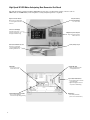
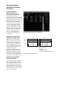
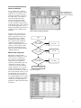
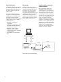
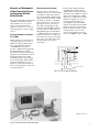
Agilent
4287A RF LCR Meter
1 MHz - 3 GHz
Technical Overview
High-Speed RF LCR Meter Anticipating Next Generation Test Needs
The Agilent 4287A is a high performance RF LCR meter best fit to production line testing of devices such as
SMD inductors and EMI filters, where impedance testing at high frequencies is required.
Signal-level monitor function
Monitors the test signal voltage
or current applied to the device
under test.
8.4 inch color LCD display
Selectable measurement
parameters (4 parameters can
be displayed simultaneously)
Small test head with 1m test cable
Extension to an automated
component handler without
introducing additional error
LAN interface
• For remote test control
and fast data transfer
Rdc (DC resistance)
measurement function
For contact check
Navigation keys and rotary knob
Support front panel operation
without the mouse
3.5 mm (female) test port
External VGA output
• Display measurement results
on a larger VGA monitor
Opto-isolated handler interface
• Easy integration with an automatic
component handler
• Highest throughput in automatic
component test handshaking
External keyboard and mouse interface
• Easy to use by simplifying
measurement setup and programming
2
GPIB interface
• Controlled by external PC.
(cannot control external devices)
The 4287A greatly increases
manufacturing testing efficiency
with fast measurement speeds
(9 msec/point) and a statistical
analysis function, among the other
powerful functions, such as the
built-in comparator function. In
addition, the 4287A improves upon
the measurement accuracy and
impedance measurement range
of previous RF LCR meters. These
improvements are realized by
advanced techniques in analogcircuit design. The 4287A achieves
better measurement repeatability
and stability, even at the low
test-signal levels required for
SMD inductor testing.
Setup display select menu
Setup editor
Changes can be made easily
with the mouse or navigation keys
User-friendly interface
An object-oriented user interface
that is navigable using the mouse,
panel keys or keyboard simplifies
complicated measurement setup
procedures. Setups, including test
frequency, signal level (also when
using list-sweep), and limits for the
multi-function comparator, can be
performed and verified easily by
editing the setup-tables. The setup
editor has eight page tables and
can store eight different setups.
After the setup tables have been
established, the active measurement
setup can be chosen simply by
selecting the corresponding number
(1 through 8).
8 page setup tables
Figure 1. List sweep setup display
Key specifications
Test frequency
1 MHz - 3 GHz with 100 kHz resolution.
With list-sweep, up to 32 points per sweep is available.
Impedance parameters
|Z|, θz (rad), θz (deg), |Y|, θy (rad), θy (deg), X, G, B, Ls, Lp, Cs, Cp, Rs, Rp, Q, D
Display resolutions
5 digits
Test signal level
V (open condition): 4.47 mVrms - 502 mVrms (447 mVrms when >1 GHz)
I (short condition): 0.0894 mArms - 10 mArms (8.94 mArms when >1 GHz)
Basic accuracy
± 1.0%
Measurement range
200 mΩ to 3 kΩ (@1 MHz, accuracy ≤10%)
Measurement time
9 msec per point (max. speed)
Measurement terminal
3.5 mm (female)
Calibration and compensation
Open/short/load/low-loss capacitor calibration, fixture electrical length
compensation, open/short compensation
Rdc measurement function
For contact check (on/off selectable)
Data storage devices
About 18 Gbyte internal hard disk and 1.44 Mbyte floppy disk
Interface
GPIB, LAN (10base-T/100base-TX automatically switched), and
Opto-isolated handler interface
3
Improving Throughput
and Quality In Production
Line Testing
Accurate impedance
measurement using the
RF I-V measurement method
The 4287A uses the RF I-V
measurement method for measuring
impedance by measuring the current
flowing through a device under test
(DUT) and the voltage applied across
the DUT. These measurements of
current and voltage can be made over
the entire measurement frequency
range (to 3 GHz). RF I-V enables
accurate measurement over a wide
impedance range. The impedance
measurement range is much wider
than that of network analyzers.
For a very small inductance, on
the order of a few nH, this is a
big advantage.
Figure 2. Accurate multiple frequency impedance measurements
Stable measurements at low
signal levels with high speed
SMD inductors require testing
with test currents on the order of
100 micro-amps. It is difficult to
maintain high test-throughput with
previous RF LCR meters, since
many sequential measurements are
required when averaging to reduce
measurement variation.
Measurement stability at low-test
signal levels is improved with the
4287A making highly repeatable
measurements possible. The 4287A
can increase test throughput due to
the decrease of the averaging factor.
Contact check using the Rdc
measurement function
Contact failure between a DUT and
the measurement plane of an automatic component handler is a factor
for bin sorting error in production
line testing. Contact check using the
built-in DC resistance measurement
function improves the accuracy and
efficiency of bin sorting.
4
Ls
Q
Existing
Product
4287A
0
0.05
0.1
0.15
0.2
0.25
0.3
0.35
[nH]
Figure 3. Stability comparison at low signal level
0
0.5
1
1.5
2
2.5
3
3.5
4
4.5
DUT: 10 nH (Q = 10.6)
Conditions:
100 MHz, 200 µA, AVG = 1
3 Sigma when 100 times measurements
Accurate automated testing by
advanced calibration
It is very important to eliminate
complicated error elements caused
from the use of test fixtures and
cables that extend the test head of
the 4287A. This is especially true
for measurements that use an
automated component handler.
Accurate measurements, which
correlate well with results obtained
from manual testing, can be achieved
at the measurement plane of a test
fixture by performing open/short/load
calibration with a “working” load
standard.
In other words, open/short/load
calibration, at the measurement
plane is dependent solely on the
value assigned to the “working
standard” by manual testing of
that component. Since different
calibration standard reference
values can independently be set at
each list sweep frequency, multifrequency measurements can be
made accurately with this reliable
calibration function
Different calibration reference
values can independently be
set at each list sweep frequency
Figure 4. Calibration standard data setup display
START
Meets conditions
#1 to #4 of BIN1?
YES
NO
Meets conditions
#1 to #4 of BIN2?
Multi-function comparator
The 4287A is equipped with a
multi-function comparator to meet
a wide variety of testing needs.
The comparator setup display is
formatted as a table. Each row
represents a bin number, and each
column represents the sorting
conditions for each bin. When all
sorting conditions set for a bin are
satisfied, the judgement result is
sorted to the bin. There are thirteen
bins, with four limit values for each
bin. Conditions such as frequency
and measurement parameters can
be set independently in each column,
enabling the 4287A to meet various
sorting needs, including different
parameters at different measurement
frequencies.
Sorts to BIN1
Sorts to BIN2
YES
NO
Meets conditions
#1 to #4 of BIN13?
Sorts to BIN13
YES
NO
Sorts to OUT_OF_BINS
Figure 5. Bin-sort sequence
Figure 6. Comparator setup display
5
Statistical functions
Data storage
The 4287A is equipped with functions
to statistically analyze data. These
functions improve the efficiency of
the data acquisition required in
quality control.
The 4287A built-in data storage
includes a 3.5 inch floppy disk drive
as well as a hard disk drive. These
powerful storage devices permit
save and recall of measurement
setup parameters (instrument state)
and measurement data. In addition,
measurement setup parameters
and data can be transferred between
the 4287A and an external computer
via the GPIB or LAN interface.
The statistical analysis function
calculates the following statistical
parameters for as many as 240000
measurement points. Original
measurement results for the statistical
analysis function can be obtained
via LAN interface.
• Examples of normal data
(non-failure)
Cumulative normal samples, mean,
maximum, minimum, standard
deviation, and 3 σ/mean
• Examples of failure analysis
Cumulative failure samples,
cumulative Rdc failures, cumulative
overload samples
• Total number of normal/failure
data
Interfacing with an automated
component handler
The measurement plane can be
extended from the front panel of
the instrument to the measurement
stage with the 1 m test cable and the
small size test head. Note that the
measurement accuracy is specified at
the test head. It is possible to extend
the test cable an additional meter
with a 1 m extension cable. In
addition, connection to an external
computer or an automated component
handler can be accomplished via the
GPIB interface and the opto-isolated
handler interface. The LAN interface
enables network communication,
and greatly empowers massive data
transfer to a remote computer.
PC
LAN
GPIB
Handler
Handler I/F
3.5 mm
Small test head
4287A
1 m cable
( 2 m max. (Option 4287A-020))
Figure 7. Handler system example with the 4287A
6
Research and Development
of Next Generation Devices
and Improving Reliable
Quality Control
The accurate impedance measurement
capability of the 4287A with the
various kinds of test accessories
offers you total measurement
solutions for the areas of research
and development, as well as quality
control.
Accurate impedance evaluation
up to 3 GHz
Characterization of components at
operating frequencies in excess of
2 GHz is becoming common due to
the development and evaluation
of RF SMD inductors used in
wireless communication equipment.
The 4287A employs the RF I-V
measurement method of measuring
impedance by measuring the current
flowing through a device under
test (DUT) and the voltage applied
across the DUT. The 4287A enables
accurate measurement over an
impedance range much wider than
that of network analyzers (reflection
coefficient method).
Total measurement solution
When electronic components are
evaluated, the test accessories should
be suitable for their shape and size
for accurate impedance measurements.
Agilent offers various kinds of 7-mm
test fixtures, which are compatible
with the 4287A. You can select the
appropriate one for your device's
size, shape, and application. The
16196A, B, C and D SMD test fixtures,
developed with a coaxial structure,
make RF impedance measurements
to 3 GHz possible. The 16196A, B, C
and D correspond to the chip sizes,
1608 (mm)/0603 (inch), 1005 (mm)/
0402 (inch), 0603 (mm)/0201 (inch),
and 0402 (mm)/01005 (inch)*
respectively.
The repeatable DUT positioning
capability and reliable contacts
enable stable measurement results,
and reduce the possibility of operator
induced error. Evaluation of SMD
inductors to 3 GHz, which has been
difficult to implement so far, can
easily be performed with good
repeatability by using the 4287A
with the 16196A/B/C/D test fixtures.
When the 16200B is used with the
4287A, a 7 mm test fixture, and an
external dc bias source, dc bias
current can be applied to devices
such as the EMI filter (up to 1 GHz).
Cap
Upper electrode
DUT
Insulator
Outer connector
Lower electrode
7 mm connector
Figure 8. Cross-sectional drawing of 16196A/B/C
*EIAJ/EIA chip size code
Figure 9. Total measurement solution example (with 16196A)
7
Advanced Features For
Precise and Versatile
Analysis
100
90
For manual measurements, a
low-loss capacitor as a phase
calibration standard, in addition
to open/short/load calibration,
improves the accuracy of Q
measurements as shown. In
addition to calibration, electrical
length compensation for a fixture
with open/short compensation
fully correct measurement error
caused by use of a test fixture.
These functions realize high
absolute measurement accuracy
at the measurement plane, which
in turn empowers accurate
measurement of working standards.
Qx=300
80
Q Accuracy (∇Q x / Q x) [%]
Powerful calibration and
compensation functions
70
60
50
40
Qx=100
30
20
10
0
1M
10M
100M
1G
3G
Frequency [Hz]
Figure 10. Q accuracy @ 7-mm port (typical)
Calibration wizard function
The 4287A offers you the
sophisticated calibration/
compensation method, calibration
wizard function. The calibration
wizard function eliminates errors
of troublesome calibration/
compensation procedures, and
it allows you to easily make the
4287A ready to measure accurately.
Figure 11. Calibration wizard (fixture connection
after calibration)
Figure 12. Calibration wizard (open compensation)
Frequency characteristics by
using list sweep function
In the area of research and
development, the frequency
characteristics of the device
can be required for their circuit
demands. The 4287A’s list sweep
functions enable impedance
measurements at a maximum of
256 multiple frequency points
(= 32 points max./table x 8 table
max.). By using an external PC,
spreadsheet software, and
LAN interface, the frequency
characteristics can be plotted
in a graph as shown below.
8
Figure 13. Frequency characteristics plot using spreadsheet software
Ordering Information
4287A RF LCR meter
Furnished accessories:
•
•
•
•
Test head with 1 m test cable
N (m) - SMA (f) Adapter
Wrench for 3.5/SMA connector
CD-ROM (Operation manual, Programming manual
and Sample Program)
• Power cord
Note: A keyboard and a mouse are required for initial
setup of 4287A.
Options
4287A-004
4287A-020
4287A-700
4287A-710
4287A-720
4287A-810
4287A-820
4287A-1A7
Add working standard set1
Add test fixture extension cable set (1 m)
16195B calibration kit2
Test fixture stand
3.5 mm to 7 mm coaxial adapter
Add keyboard
Add mouse
ISO 17025 compliant calibration
Paper manual options
4287A-ABJ
4287A-ABA
4287A-0BW
Japan-Japanese localization
U.S.-English localization
Add service manual
Cabinet options
4287A-1CM
4287A-1CN
4287A-1CP
Rack flange kit
Front handle kit
Handle/rack mount kit
Note:
1. This is used to calibrate the 4287A at the handler DUT contacts. It consists of shorting bars, and 51.0 Ω chip resistors. (SMD size: 1.0 x 0.5 mm, 1.6 x 0.8 mm, 2.0 x 1.2 mm, 3.2 x 1.6 mm)
2. The 16195B is used to calibrate the 4287A at the 7 mm calibration plane by using the 3.5-mm to 7-mm adapter. It consists of open, short, load, and low-loss capacitor standards.
9
Accessories
16197A SMD test fixture
16196A/B/C/D SMD test fixture
- Frequency range: DC to 3 GHz
- Connector: 7-mm
- Operating temperature range:
55 °C to +85 °C
- Accommodate SMD sizes:
3216 (mm)/1210 (inch)
3216 (mm)/1206 (inch)
2012 (mm)/0805 (inch)
1608 (mm)/0603 (inch)
1005 (mm)/0402 (inch)
- Frequency range: DC to 3 GHz
- Connector: 7-mm
- Operating temperature range:
–55 °C to +85 °C
- Accommodate SMD sizes:
- 16196A: 1608 (mm)/0603 (inch)
- 16196B: 1005 (mm)/0402 (inch)
- 16196C: 0603 (mm)/0201 (inch)
- 16196D: 0402 (mm)/01005 (inch)
16194A High temperature
component fixture
- Operating frequency: DC to 2 GHz
- Operating temperature range:
–55 °C to +200 °C
- Accommodated SMD size:
See Figure 19.
Figure 17. 16194A
16200B External DC bias adapter
Figure 14. 16196A/B/C. 16196D has a different
cap shape.
16192A SMD test fixture
Figure 16. 16197A
- Operating frequency: 1 MHz to 1 GHz
- External DC bias: 5 A max, 40 V
(at the BNC connector from the
external dc bias source)
- Operating temperature range:
0 °C to +55 °C
- Operating frequency: DC to 2 GHz
- Accommodated SMD size:
See Figure 19.
Figure 18. 16200B
Figure 15. 16191A/16192A
16192A
16197A
L = 1.0 - 20.0 mm
L = 1.0 - 3.2 mm
L
L
16194A
L = < 15 mm
L = < 4.5 mm
L = 2.0 - 15.0 mm
L
L = 8.0 - 21.0 mm
H
L
Figure 19. Accommodated SMD size
10
W
Ordering Information
Accessories1
16196A2
Parallel electrode SMD test fixture
Option 16196A-710 Add magnifying lens and tweezers
Option 16196A-ABA U.S. - English localization
Option 16196A-ABJ Japan - Japanese localization
16196B2
Parallel electrode SMD test fixture
Option 16196B-710 Add magnifying lens and tweezers
Option 16196B-ABA U.S. - English localization
Option 16196B-ABJ Japan - Japanese localization
Parallel electrode SMD test fixture
Option 16196C-710 Add magnifying lens and tweezers
Option 16196C-ABA U.S. - English localization
Option 16196C-ABJ Japan - Japanese localization
Parallel electrode SMD test fixture
Option 16196D-710 Add magnifying lens and tweezers
Option 16196D-ABA U.S. - English localization
Option 16196D-ABJ Japan - Japanese localization
16196U
Maintenance kits for 16196X
Option 16196U-010
Upper electrode set for
16196A/B/C (5 ea)
Upper electrode set for 16196D
(5 ea)
1608 (mm) short plate set (5 ea)
1608 (mm) lower electrode set
(5 ea)
1005 (mm) short plate set (5 ea)
1005 (mm) lower electrode set
(5 ea)
0603 (mm) short plate set (5 ea)
0603 (mm) lower electrode set
(5 ea)
0402(mm) short plate set (5 ea)
0402(mm) lower electrode set
(5 ea)
Option 16196U-200
Option 16196U-210
Option 16196U-300
Option 16196U-310
Option 16196U-400
Option 16196U-410
16192A3
Option 16192A-010
Option 16192A-710
16194A3
16196D2
Option 16196U-100
Option 16196U-110
Bottom electrode SMD test fixture
Add 0201 (inch)/0603 (mm) device
guide set
Option 16197A-ABA U.S. - English localization
Option 16197A-ABJ Japan - Japanese localization
Option 16197A-001
Option 16192A-701
16196C2
Option 16196U-020
16197A2
Option 16194A-010
Option 16194A-701
16200B
16190B4
Parallel electrode SMD test fixture
EIA/EIAJ industry sized short bar
Set
Short bars set (1 x 1 x 2.4,
1.6 x 2.4 x 2, 3.2 x 2.4 x 2.4,
4.5 x 2.4 x 2.4) mm
Add magnifying lens and tweezers
High temperature component fixture
EIA/EIAJ industry sized short
bar set
Short bars set (1 x 1 x 2.4,
1.6 x 2.4 x 2, 3.2 x 2.4 x 2.4,
4.5 x 2.4 x 2.4) mm
External DC bias adapter
Performance test kit, 7-mm
Note:
1. Manual is not furnished as standard.
2. Must specify one of language options (ABA or ABJ) for operation manual for shipment with product. For 16196A/B/C/D, magnifying lens and tweezers are not furnished as standard.
3. Short bar set is not furnished as standard. Magnifying lens and tweezers are not furnished as standard.
4. This kit includes an open, a short, a 50 Ω terminations, and an air line for the performance test to verify the impedance accuracy.
11
Web Resource
www.agilent.com/find/lcrmeters
Agilent Email Updates
www.agilent.com/find/emailupdates
Get the latest information on the products
and applications you select.
Agilent Direct
www.agilent.com/find/agilentdirect
Quickly choose and use your test
equipment solutions with confidence.
Remove all doubt
www.agilent.com
Our repair and calibration services will get
your equipment back to you, performing
like new, when promised. You will get
full value out of your Agilent equipment
throughout its lifetime. Your equipment
will be serviced by Agilent-trained technicians using the latest factory calibration
procedures, automated repair diagnostics
and genuine parts. You will always have the
utmost confidence in your measurements.
For more information on Agilent
Technologies’ products, applications
or services, please contact your local
Agilent office. The complete list is
available at:
www.agilent.com/find/contactus
Americas
Canada
Latin America
United States
(877) 894-4414
305 269 7500
(800) 829-4444
Agilent offers a wide range of additional
expert test and measurement services for
your equipment, including initial start-up
assistance onsite education and training,
as well as design, system integration, and
project management.
Asia Pacific
Australia
China
Hong Kong
India
Japan
Korea
Malaysia
Singapore
Taiwan
Thailand
1 800 629 485
800 810 0189
800 938 693
1 800 112 929
0120 (421) 345
080 769 0800
1 800 888 848
1 800 375 8100
0800 047 866
1 800 226 008
For more information on repair and
calibration services, go to
www.agilent.com/find/removealldoubt
Europe & Middle East
Austria
0820 87 44 11
Belgium
32 (0)2 404 93 40
Denmark
45 70 13 15 15
Finland
358 (0)10 855 2100
France
0825 010 700*
*0.125 ¤/minute
Germany
01805 24 6333**
**0.14 ¤/minute
Ireland
1890 924 204
Israel
972-3-9288-504/544
Italy
39 02 92 60 8484
Netherlands
31 (0)20 547 2111
Spain
34 (91)631 3300
Sweden
0200-88 22 55
Switzerland
0800 80 53 53
United Kingdom 44 (0)118 9276201
Other European Countries:
www.agilent.com/find/contactus
Revised: March 27, 2008
Product specifications and descriptions in
this document subject to change
without notice.
© Agilent Technologies, Inc. 2000, 2003,
2004, 2005, 2008
Printed in USA, April 10, 2008
5968-5443E