1
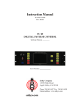
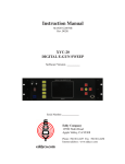
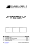
Instruction Manual
MANLM101070C
REV. D0202
LM-101
LIGHT MONITOR
Eddy Company
13590 Niabi Road
Apple Valley, CA 92308
Phone: 760-961-8457 Fax: 760-961-8458
Internet address: www.eddyco.com
TABLE OF CONTENTS
GENERAL INFORMATION:
Basic Description .....................................................................................
Limited Warranty .....................................................................................
Unpacking/User Responsibility ...............................................................
Operator Safety ........................................................................................
1
2
3
4
DESCRIPTION AND SPECIFICATIONS:
Front Panel Description ...........................................................................
Rear Panel Description ............................................................................
LM-101 Specifications ............................................................................
5
6
7
INSTALLATION:
Initial Startup ...........................................................................................
Initial Operation Checkout ......................................................................
8
8
CALIBRATION PARAMETERS:
Recorder Output ......................................................................................
Acc. Output Calibration ...........................................................................
Output Offset Calibration ........................................................................
Electronic Zero ........................................................................................
Meter Calibration .....................................................................................
Source Light Voltage Adjustment ............................................................
Filter Phase Adjustment ...........................................................................
Filter Tuning Procedure ...........................................................................
IR Power Supply ......................................................................................
IR Detector Adjustment ...........................................................................
9
9
9
9
9
10
10
10
10
10
ENGINEERING DRAWINGS:
Complete Schematic SChLM1010001 ...................................................
Main Board Layout LM101ASY060B ...................................................
IR Power Supply SCHLM1010004 ........................................................
IR Power Supply Layout LM101ASY0004 ...........................................
Monochromator SCHLM101MR05 .......................................................
IR Detector Amp SCHLM101CRO ........................................................
SI Detector SCHLMC10072B ................................................................
PMT 101-102 ...........................................................................................
A
B
C
D
E
F
G
H
BASIC DESCRIPTION
The LM-101 Optical Monitor provides the optimum in economical deposition control using
optical parameters. Automatic phase locking and zeroing simplify operation. Digital offset
and 10 to 1 scale expansion provide unparalleled resolution. Visible and
IR range are available. Available options include monochromators and PMT detectors from
180 nm to 850 nm with internal stable power sources and preamplifiers.
1
LIMITED WARRANTY
This LM-101 Light Monitor is warranted against defects in materials and workmanship for a
period of one year from the date of shipment to the original purchaser. This warranty will be
void if the instrument is not properly operated under conditions of normal use and if normal
and accepted maintenance protocols are not performed.
Defects resulting from, or repairs necessitated by, improper installation, misuse, negligence,
accident or corrosion of the equipment or any cause other than defective materials or
workmanship are not covered by this warranty. No other warranties are expressed or
implied, including but not limited to the implied warranties of merchantability and fitness for
a particular purpose. EDDY Company is not liable for consequential damages resulting from
the use of its equipment.
Purchaser’s sole and exclusive remedy under the above warranty is limited to EDDY
Company, at its option, repairing or replacing any item which proves to be defective during
the warranty period provided the item is returned to EDDY Company together with a written
statement of the problem encountered. Any such obligation on the sellers part is subject to
the following requirements: 1) defect must be promptly reported to the seller, 2) if so
advised by the seller, component must be returned to the seller, no later than seven (7) days
after the end of the warranty period, and 3) on examination by the seller the part or
component must be found to comply with the above warranty. Any item claimed to be
defective during the warranty period must be returned to the builder with the transportation
charges prepaid. Return trip transportation charges will be paid by the purchaser. In the
event that the seller elects to refund the purchase price, the instrument shall be the property
of the seller and shall be promptly shipped back to the seller at the sellers expense. EDDY
Company reserves the sole right to determine whether service is covered by the warranty.
If there are any questions about any of the equipment, parts or service call EDDY Company.
For all repairs, whether or not they are covered by the warranty, first call EDDY Company
service line or our Internet address.
Phone number: 760-961-8457
Internet:
www.eddyco.com
If the equipment needs to be returned for any reason you will be given a Return Material
Authorization (RMA) number.
2
UNPACKING
1. Completely unpack the instrument. Your LM-101 was released to the carrier in good
condition and properly packed. It is essential to examine the contents of the shipment
to ensure that no damage occurred during transit.
2. Compare the shipped materials to the packing list. Items included with your LM-101
are:
a. LM-101 Light Monitor
b. Operation and service manual
c. Power cord
d. Installation kit: Strip chart recorder cable; 1 – 2 amp SB fuse; 1 – 6 amp SB
fuse.
3. Call EDDY Company first if there are any problems.
Phone: 760-961-8457
FAX: 760-961-8458
USER RESPONSIBILITY
This equipment will perform in accordance with the instructions and information contained
in the user’s manual when the equipment is installed, operated, and maintained in compliance
with the instructions. Equipment should be checked periodically, routine maintenance
performed, and broken or non-working parts replaced immediately.
The user/purchaser shall have sole responsibility for any malfunctions resulting from their
improper use or lack of maintenance of the equipment.
3
OPERATOR SAFETY
DANGER:
Potentially lethal voltages may exist within this unit, even with the power shut
off. Only qualified personnel should attempt service. Failure to observe all
safety precautions may result in personal injury.
Observe the following precautions when servicing this instrument because of the potential
high voltage.
1. Make sure HIGH VOLTAGE WARNING signs are posted in the service area.
2. Remove rings, watches, bracelets, and any other metal jewelry before
working around high voltage.
3. DO NOT WORK ALONE.
4. Be sure all equipment is connected to a power source that has the correct
polarity and grounding, as prescribed by the local electrical codes.
5. Before servicing equipment be sure it is switched off at the main power switch
This switch should have a lock out feature.
6. Use a grounding hook to discharge any electrical parts that hold a lethal voltage
after shutoff. Be sure these parts are discharged before attempting any repairs.
7. Do not touch any high voltage leads unless the power is off and a grounding
hook is connected to the parts being serviced.
8. This instruments high-voltage components are equipped with electrical
interlocks to protect personnel from injury. DO NOT ATTEMPT TO DEFEAT,
OVERRIDE, OR BYPASS THESE PROTECTIVE DEVICES.
9. Never leave loose ends on high voltage devices.
4
FRONT PANEL
INTENSITY
GAIN
ZERO
MULTIPLIER
POWER
SOURCE
INTENSITY
DETECTOR
100
10
1K
A
HIGH
1
10K
TIME
CONSTANT
.2
.5
2
.1
.05
LOW
OFF
OFF
E
D
D
Y
B
LIGHT MONITOR
LM-101
1
1.0
METER
OUTPUT
OFF
OFF
5
10
POWER ON:
Turns on power to unit.
Red LED indicates power supplies are functional.
SOURCE:
Turns on lamp power supply and IR Detector power supply.
Green LED indicates source lamp and power supply are working.
INTENSITY:
Selects one of two pre-set power settings for the lamp.
Low 10.5 volts - 2000 hours life
High 11.5 volts - 100 hours life
DETECTOR:
In the up position this connects input A to monitor; down connects
input B to the monitor.
MULTIPLIER:
Decade gain switch for establishing optimal range.
GAIN:
Fine gain adjustment. The gain has a ten turn potentiometer with
gain from 10% to 100%.
TIME CONSTANT: Adjusts the dynamic response of the units in seconds.
INTENSITY:
3 1/2 digit linear display of light intensity.
OFFSET:
Shifts zero reference of light reading signal.
METER SWITCH:
In the up position it connects offset signal to digital display, reducing
the reading by the amount of the offset.
OUTPUT SWITCH: In the up position subtracts offset switch to recorder output.
ZERO:
Press to block light path and electronically zero unit.
RECORDER EXPANDER:
Multiplies intensity signal by the factor selected (scale expansion).
5
REAR PANEL
INPUT A
INPUT B
RECORDER
2A S.B.
POWER
SOURCE
6 AMP
105-125 V.A.C.
50/60 HZ
INPUT A:
Connects detector to monitor and provides preamp and gain changing power.
INPUT B:
Connects detector to monitor and provides preamp and gain changing power.
RECORDER: Provides 0 – 100 mv DC output signal proportional to display reading. It may
be changed to give 0-10 mv, 0-1 to 0-10V by changing 1 internal resistor.
SOURCE:
Provides lamp, chopper, beam flag, and sync power.
FUSE 1:
Primary fuse power.
FUSE 2:
Lamp power fuse.
POWER:
3 prong 105-125 VAC 50/60 HZ power input.
6
LM-101 LIGHT MONITOR SPECIFICATIONS
CABINET:
WEIGHT:
SHIPPING WEIGHT:
AC INPUT VOLTAGE RANGE:
LINEARITY:
LAMP STABILITY:
COMPENSATION RANGE (gain):
RECORDER OUTPUT:
3 1/2” X 19” X 9” deep
18 lbs.
22 lbs.
105 – 125 VAC 50/60 Hz, 2 amps.
Better than .05%
Voltage 0.1 % if input power is 105 – 125 VAC
Voltage 0.05%/C degrees of environmental
temperature.
5 times + ten-turn vernier potentiometer.
100 mv with expansion of 1x, 2x, 5x, and 10x.
DETECTORS
VISIBLE:
detector
INFRARED
SOURCE POWER:
UV enhanced, selected low noise silicon
and preamp. Range is 350 –1100 nm.
PBS detector with a range of 1000 to 3000 nm.
Includes a low noise power supply retrofitted in
the Light Monitor.
+ 47.5 VDC
- 47.5 VDC
10.5/11.5 VDC regulated to + - .01%
7
INITIAL STARTUP
1. Read the manual.
2. Connect all shipped parts.
3. After reading the manual, establish that all the connected instruments are working
properly.
INITIAL OPERATION CHECKOUT
1. Mount the Source and the Detector on a vibration free support.
2. Connect the Source to the Monitor and the Detector to INPUT A.
3. Position all toggles switches down, all selector switches CCW and set OFFSET to zero.
4. Turn on the power.
5. Red LED will light up and indicate power is on.
6. Turn on the SOURCE (up).
7. Green LED will light indicating the lamp and power supply are operating.
8. Place Detector switch in the A position.
9. Press ZERO and hold down. The light path will be blocked and the INTENSITY reading
will electronically zero.
10. Increase the MULTIPLIER (coarse adjustment) and the GAIN (fine adjustment) to get
the desired reading.
11. Block the beam and note the rate of INTENSITY reading change.
12. Set the maximum time constant (1).
13. Block the beam and note a slower response.
14. Set OFFSET to the same value as the INTENSITY reading.
15. With METER switch up the INTENSITY signal should be near zero.
8
RECORDER OUTPUT
1.
2.
3.
4.
5.
6.
Connect the recorder to RECORDER jack on the LM-101.
Set recorder for 100 mv full scale.
Turn on LM-101 and set GAIN to give a 1000 reading.
Adjust the recorder to read full scale.
Reduce the GAIN to give a reading of 50 on the display.
Change RECORDER EXPANDER setting and note the reading is multiplied by the
setting selected..
7. Return RECORDER EXPANDER to “1” and change the GAIN to give approximately a
550 reading.
8. Set OFFSET to 500 and turn on the OUTPUT (switch up), note the RECORDER reading
will be decreased by the value selected in the offset pot.
ACC. OUTPUT CALIBRATION
1. Connect DVM to ACC. pin 2.
2. With the METER offset on, the RECORDER EXPANDER at 2, and the OFFSET at 000,
adjust R67 to give zero output.
OUTPUT OFFSET CALIBRATION
1.
2.
3.
4.
Connect the DVM to IC-7 pin 6.
Set the OFFSET to 000 and the METER offset on.
Adjust R51 to give zero reading.
Set the OFFSET to 1000 and adjust R49 to give 10.00v reading.
ELECTRONIC ZERO
1.
2.
3.
4.
METER offset on.
Connect DVM to IC-8 pin 6
Press ZERO and adjust R31 to give zero output.
While holding ZERO in, adjust the PANEL meter pot, (right side behind front bezel), to
give 000 reading.
METER CALIBRATION
1.
2.
3.
4.
With no signal, check the INTENSITY meter for 000 reading.
Dial 1000 in the OFFSET pot and turn on METER offset.
Adjust R53 to give 1000 reading.
Turn off the OFFSET switch and check for zero reading.
9
SOURCE LIGHT VOLTAGE ADJUSTMENT
1. Connect DVM from the common of R57 and R58 to the common of R16 and R62. This
will give the source light’s voltage.
2. Connect the source to the monitor, set the INTENSITY to High and adjust R59 for the
desired voltage (factory value 11.5V). Change the INTENSITY to Low and adjust R60
for the desired voltage (factory value 10.5V).
FILTER PHASE ADJUSTMENT
1.
2.
3.
4.
5.
Connect the scope to the center terminal of T5.
Adjust the source and detector to give about 1000 signal on the INTENSITY meter.
Vary the settings of R28 and R29 to give the highest signal.
Remove the case on the source and bend the bracket to give the best-rectified sine wave.
Readjust R28 and R29 for maximum signal.
FILTER TUNING PROCEDURE
1. Connect the scope to IC2 output.
2. Adjust R29 and R10 to give the maximum signal (200 Hz sine wave).
3. Connect the scope to the center tap of T1 and “bend” the sync board on the source to give
the “best” rectified sine wave.
4. Fine-tune this sine wave with R9 and R10.
IR POWER SUPPLY
1.
2.
3.
4.
5.
Turn on the POWER and then the SOURCE switch of the LM-101.
Set R5 on the IR board to give maximum voltage across C10.
Set R12 to give 95.0 volts across C10.
Set R5 to give 108.0 volts across C10.
Set R15 to make + an – voltage out equal (about 47.5 volts).
IR
DETECTOR ADJUST
1.
2.
3.
4.
5.
Turn power on.
Block all light from the detector.
Set LM-101 GAIN to 1000.
Adjust R41 to give zero voltage out.
With normal signal into the detector, adjust R5 to give zero voltage at junction of C3, R5,
and the detector.
10
A
THE EDDY CO.
LM-101
APPLE VALLEY CA. 760-9618457
MAIN BOARD
A
WER
LM101ASY060B
A
-BA -
C
LM-101
WER
A
THE EDDY CO.
IR POWER SUPPLY LAYOUT
APPLE VALLEY CA. 760-9618457
D
A
LM101SERVI01
LM101MIQCBL1
MM1
MOTM1616C11
BLU1
+
RED1
-
J1
M-7 AMPHENOL CONN A
GRN
CCW
A
B
C
D
E
F
H
P4
F-14 PIN PLUG
1
BLACK
GREEN
BLUE
YELLOW
WHITE
RED
P1
F-7 AMPHENOL CONN
WHITE
RED
GREEN
YELLOW
BLACK
BLUE
2 RED#
R1
10K 10T
CW
YEL
BLA1
L1
SOLENOID
BLU
CBL1179-20'
1
1
1
J2
2 PIN CONN
2 P2
2 PIN CONN
ISA MONO
THE EDDY CO.
A
APPLE VALLEY CA. 92308
SCHLM101MR05
10/6/00
F
E
R3
2.4K 1/4W 5%
Q1
C2
.022UF 100V 230B
E111
G
D
# 1 PAD X100 BLACK
49.9K 1/4W 1%
S
R7
PCB P1
8 PIN CONN
1
R2
R1
5M 1% MOX
50M 1% MOX
SIGNAL YELLOW
GND SHEILD
X100 BLACK
+15 RED
-15 GREEN
+47.5 BLUE
-47.5 WHITE
220PF 160V SF
# 2 PAD SIGNAL YELLOW
C1
IC1
1
NULL
2
3
4
8
STRB
# 3 PAD +15 RED
7
V+
IN-
6
OUT 5
NULL
IN+
V-
3140
3
1
C5
.1UF 100V 230B
R4
10K
2
# 7 PAD -15 GREEN
C3
1UF 35V TA
C4
1UF 35V TA
# 4 PAD GND SHEILD
R6
100K
IR DET1
3
1
1
R5
499K 1/4W 1%
# 5 PAD +47.5 BLUE
2
# 6 PAD -47.5 WHITE
20' CBL
LM-101R
THE EDDY CO.
SANTA MONICA CA.
213-8284157
I.R. DET AMP
C
WER
SCHLM101CR0
11-30-90
A
F
C2
2.4K 1/4W 5%
R3
Q1
E111
G
D
# 1 PAD X100 BLACK
.022UF 100V 230B
#6
F-14 PIN PLUG
1
SIGNAL YELLOW
GND WHITE
X100 BLACK
GND WHITE
+15 RED
-15 GREEN
49.9K 1/4W 1%
S
R2
R1
5M 1% MOX
220PF 160V SF
C5
5UF 35V
C1
R5
121K 1/4W 1%
R4
121K 1/4W 1%
SD290-12-12-241
DET1
IC1
1
NULL
STRB
2
3
4
V+
ININ+
V-
8
7
# 3 PAD +15 RED
6
# 5 PAD SIGNAL YELLOW
OUT 5
NULL
# 2 PAD -15 GREEN
3140
C4
1UF 35V TA
C3
1UF 35V TA
# 4 PAD GND WHITE
CBL8786-2'
LMC-10
THE EDDY CO.
APPLE VALLEY CA. 92308
SI DET.
A
WER
SCHLMC10072B
4-30-92
B
G
PMT-101
PMT-102
THE EDDY CO.
SCHEMATIC
C
WER
SANTA MONICA CA.
SCHPMT10X003
10-25-90
213-8284157
H
C
SHIELD
SIGNAL
BLACK
RED
WHITE
BLUE
PS1
HC123-01
2
1
3
PAD
PAD
PAD
PAD
#1
#4
#3
#2
# 1 0 PAD
R8
10K
GAIN ADJUST
R6
2.4K 1/4W 5%
E111
Q1
G
C2
5UF 35V
R5
121K 1/4W 1%
4
3
2
1
3140
IN+
V-
IN-
NULL
IC1
8
6
7
OUT 5
NULL
V+
STRB
R1
5M 1% MOX
C1
2200PF 160V SF
R4
121K 1/4W 1%
C3
.022UF 100V 230B
R7
49.9K 1/4W 1%
C4
22OUF 16V ELECT
D
S
IC2
8
6
7
# 7 PAD GREEN -15
# 8 PAD WHITE GND
# 6 PAD RED +15
C5
OUT 5
NULL
V+
STRB
.1UF 35V TA
3140
IN+
V-
IN-
NULL
RED +15
GREEN -15
P1
8 PIN CONN
YELLOW SIGNAL 1
WHITE GND
BLACK X100
CBL8786-2'
PAD YELLOW SIGNAL
C6
4
3
2
1
#5
PAD BLACK X100
.1UF 35V TA
R2
10K 1/4W 1%
R3
10K 1/4W 1%
#9