1
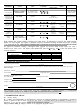
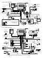
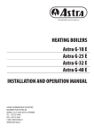
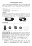
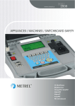
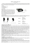
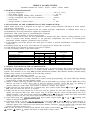
VEHICLE ALARM SYSTEM
Installation Manual for ‘GN5S’, ‘GN5G’, ‘GN5A’, ‘GN6A’ models
1. TECHNICAL SPECIFICATIONS:
P operating temperature ………………………………..….............. - 40° C to +85° C;
P rated supply voltage …………………………………….............. 9 – 15V DC;
P average consumption without sensor connected………............... <14mA;
P average consumption with US2 sensor connected.......…............ <20 mA;
P siren current ………………………………................................... 2A;
P average distance of remote control ……………………............. 5 – 10m.
2. INSTALLATION OF THE COMPONENTS OF THE ALARM SYSTEM.
Vehicle alarm system 'GN' is designed for all types of vehicles (except cabriolets) with petrol or diesel engines,
12V negative earth batteries.
Vehicle alarm system must be installed inside the vehicle passenger compartment, in difficult access area as
recommended by the wiring instructions supplied by manufacturer.
Manufacturer of the alarm system is recommending the following:
a) selecting a qualified installer of vehicle alarm systems;
b) mounting system unit in place free from penetration of moisture and other corrosion - causing materials, as far
away as possible from heating elements in the passenger compartment and sources of electromagnetic
interference (vehicle computer, conditioner, block of relays);
c) avoid mounting system unit directly onto metal parts of vehicle to prevent accumulation of condensate in the
system unit;
d) mounting system unit in a way wire connectors are going from the bottom side of the unit;
e) avoid placing wires adjacent to moving or hot parts of vehicle;
f) avoid overloading circuits of the alarm system:
CIRCUIT
lock impulse current
unlock impulse current
cut-off circuit /CC1
siren activation circuit
right direction indicator control circuit
left direction indicator control circuit
CIRCUIT MARK
'GN6'
'GN5'
6
4
7
3
4
6
/
1
1
5
5
2
2
8
MAX VALUE
0,13 A
0,13 A
0,13 A
2A
7A
7A
3. SETTING FUNCTIONS OF THE ALARM SYSTEM.
Depending on the program version, 'GN' can incorporate up to 49 system settings. Due to these settings 'GN' can
be adjusted to some particular vehicle or to country related traditions, or existing requirements for vehicle alarm
systems. 'GN' functions are set using PIN (personal identification number), FN (function number) and SN (setting
number) codes. Actions to be performed in the following sequence:
a) Open vehicle doors and leave it opened;
b) Enter PIN code (see User Manual 6.2.), close the doors;
c) Wait for approximately 12 seconds (intended for remote control pre-programing), till system LED stops flashing
in triple bursts of light and starts flashing rapidly;
d) Within 8 minutes following the PIN code entry enter the FN number (by analogy with the PIN code) of the
function you want to change. Short flash of direction indicators indicates correct FN entry. No flashing of
direction indicators, means either incorrect FN or dedicated 8 minutes have elapsed;
e) If FN code has not been entered due to elapsed time, press remote control button M or
or
, enter the
PIN code once more and wait for 12 seconds;
f) If FN code has not been entered due to the error, turn the ignition off, wait until system LED starts flashing
rapidly and repeat the FN code. After correct entry of the FN code the system ex tends control time for 8
minutes awaiting a code from remote control button I or
or
. Within this control time check current SN
settings or enter a new one. The system again extends control time to 8 minutes;
g) Check SN setting only with the ignition OFF. Press remote control button I or
or
counting short
flashes of direction indicators;
h) If function setting is not met, turn the ignition ON. Press button I or
or
with 1 second intervals as
many times as the desired number of SN. Wait for 3 seconds until short siren chirp and flash of direction
indicators appear. New setting has been entered into memory. Therefore, turn the ignition OFF and check SN
setting as described in article "3g".
Note: If icons are used for remote control buttons, then remote control button I matches button
, and button
M
matches
. Button
matches the button in single button remote control.
4. SUMMARY OF ALARM SYSTEM SETTING SEQUENCE.
CONDITION
ACTION
Doors opened
PIN ENTRY
REMOTE
CONTROL
-
CONTROL
TIME
-
PIN entered
REMOTE CONTROLS
PROGRAMMING
12 seconds, extended
for 12 seconds after
each remote control
programming
12 seconds after
PIN entry of
a remote control
programming
FN ENTRY
8 minutes
FN entered,
ignition OFF
SN CHECK
FN entered,
ignition ON
SN CHANGE
SN checked
or set
FOLLOWING FN
ENTRY
8 minutes
Following FN
entered,
ignition ON
SN CHANGE
8 minutes
END of
setting
FN=11 ENTERY
or using remote control
8 minutes
8 minutes
DIRECTION
INDICATORS
-
SYSTEM LED
-
Double flashing
-
-
Triple flashing,
1 second flash after
remote control
pre-programming
-
Indicates
correct FN entry
-
Double flashing
Short press of
or
or
Indicates
SN value
-
Frequent flashing
Short presses of
I
or
or
Indicates SN
change in 3
seconds
Indicates SN
change in 3
seconds
Double flashing
M
or
or
+
M
I
+
+
I
or
+
+
G
I
8 minutes
SIREN
Short presses of
I
or
or
Indicate
correct
FN entry
Indicates SN
change in
3 seconds
-
Double flashing
Indicates SN
change in 3
seconds
Double flashing
-
-
Double flashing /-
Short press of
or
or
M
5. OPERATION TESTS OF THE SYSTEM.
While operating the system performs self-testing on regular basis. If malfunction is detected, the system generates
audible 1.5 second signal. Such signal is generated only at the moment of turning the alarm ON or OFF. It differs
by its duration from the audible signals confirming that the protection has been turned ON or OFF. Do not confuse
this signal with external "warning" zone signal often triggered by incorrect tuning of the sensor. For ease of
installer's work, 'GN' saves 3 last alerts in the memory. By using the memory, causes of the false alarm can be
ascertained. To perform this enter FN=71, 72, or 73, press button I or
or
and count flashes of the
direction indicators:
REASON OF FALSE ALARM
Triggering of a sensor
Door opening
Engine bonnet opening
Luggage compartment opening
Turning ignition ON
NUMBER OF FLASHES FOR DIFFERENT MODELS
'GN5_S'
1
2
3
4
5
'GN5_G'
1
2
3
4
5
'GN5_A'
1
2
3
4
5
'GN6_A'
1
2
3
2
5
6. CERTIFICATE OF INSTALLATION .
I, undersigned qualified installer
(Name, Surname)
certify that installation of
the below described vehicle alarm system has been carried out by myself pursuant to installation manual supplied by the manufacturer of the system.
Vehicle description:
Manufacturer and model:
Serial number:
Registration number:
Description of vehicle alarm system:
Type: 'GN'. Model:
Official approval number:
Installation date:
Installing company:
SEAL
Installer:
(Position, signature)
After installation of the alarm system installer must fill in CERTIFICATE OF INSTALLATION! It is recommended
to mark selected settings in the TABLE OF ALARM SYSTEM SETTINGS (underline SN).
7. SUMMARY OF ALARM SYSTEM SETTINGS.
7.1. MARKED FIELD MEANS:
FS - factory setting;
EU - setting meets requirements of EU Directives. Selection of settings not meeting EU requirements is possible if
vehicle is operated in non EU state. In this case the system is considered having no conformity certificate, so it is
imperative to cross out the approval number in the installation certificate;
GN5_S, GN5_G, GN5_A, GN6_A - function is in appropriate program version.
FN=41 Function: ARMING WITHOUT A REMOTE CONTROL.
SN=1 Arming without a remote control function is turned OFF
SN=2 Arming without a remote control will be turned ON if, secret button is pressed twice with the ignition OFF, door opened and then closed. Central lock is locked.
FN=42 Function: WARMING-UP THE ENGINE.
SN=1 Warming-up the engine function is turned OFF
With ignition ON and secret button pressed twice in the later time, alarm is enabled and central locking is possible by pressing remote control button M or
or
. The
SN=2 system will not respond to shock or volume sensor, however in case of door opening, engine bonnet or luggage compartment, the siren starts sounding, direction indicators flashing. Depending on 'Anti-Carjack' function settings (FN=23) the engine is immobilized within 10 seconds and the system rearms or immediately after the ignition turn OFF the
engine is immobilized and alarm enabled. Alarm is disabled by pressing button I or
or
.
FN=44 Function: AUTO-REARM.
Auto - rearm with no central locking. The alarm will be activated automatically if vehicle doors, engine bonnet and luggage compartment remain unopened within 30 seconds
SN=1 after disarming. Central lock is not locked.
Auto-rearm with central locking. The alarm will be activated automatically if vehicle doors, engine bonnet and luggage compartment remain unopened within 30 seconds after disarming.
SN=2 Central lock is locked.
SN=3 Auto-rearm is disabled. Auto-rearm function is non-operational after the alarm disarming.
SN=4 Setting of a time, per which doors can be opened or closed after arlarm activated. Arming is on central lock is not locked.
SN=5 Setting of a time, per which doors can be opened or closed after arlarm activated. Arming is on central lock is locked.
FN=45
SN=1
SN=2
FN=51
SN=1
SN=2
Function: CENTRAL LOCK OPERATIONON WHEN TURNING IGNITION ON/OFF.
When ignition is turned ON, central lock is locked. When ignition is turned OFF, central lock is unlocked.
Central lock does not respond to turning ignition ON/OFF.
Function: PURPOSE OF CC1.
Additional disabling. CC1 controls relay (with normally closed contacts) that cuts off fuel pump.
Additional disabling. CC1 controls a relay (with normally opened contacts) that cuts off starter circuit
Engine bonnet or luggage compartment release impulse. Pressing remote control button
or I or
for more than 2 seconds generates negative polarity impulse in
SN=3 CC1 equal to the time of button pressing. (For model GN5.S it is necessary to turn ignition ON).
SN=4 40 seconds duration negative polarity pulse, generated on arming, is used to close the automatic windows or a sunroof
SN=5 If any door, engine bonnet or luggage compartment is opened with alarm enabled, inner zone of the sensor is triggered generating impulse for pager message.
SN=6 If any door, engine bonnet or luggage compartment is opened with alarm enabled, outer zone of the sensor is triggered generating impulse for pager message.
SN=7 CC1 designed for controlling GSM module GSW.
SN=8 Upon alarm turn ON CC1 generates negative polarity impulse which is terminated with alarm disabling.
FN=55
SN=1
SN=2
SN=3
SN=4
FN=65
SN=1
SN=2
SN=3
SN=4
SN=5
FN=66
SN=1
SN=2
SN=3
FN=71
SN=1
FN=72
SN=1
FN=73
SN=1
FN=77
SN=1
SN=2
SN=3
SN=4
SN=5
FN=88
FN=99
SN=1
Function: CENTRAL LOCK CONTROL.
Short impulse. Central lock is operated by 0.5 second impulse.
Long impulse. Central lock is operated by 4 second impulse.
Short impulse to lock, double impulse to unlock. Alarm arming generates 0.5 second pulse, disarming two 0.5 second impulses with 1 second intermission.
Double impulse. Central lock is operated by two 0.5 second impulses (with 1 second pause) generated by alarm arming and disarming.
Function: TYPE OF SIREN AND SOUND LEVEL.
Siren with no inner modulation (speaker with coil impedance at least 4 Ohm). Maximum sound level.
Siren with no inner modulation (speaker with coil impedance at least 4 Ohm). Sound level reduced 2 times.
Siren with no inner modulation (speaker with coil impedance at least 4 Ohm). Sound level reduced 4 times.
Siren with no inner modulation (speaker with coil impedance at least 4 Ohm). Sound level reduced 8 times.
Siren with inner modulation (standard) controlled by voltage.
Function: SIREN SIGNAL ON ARMING OR DISARMING.
Silent. Arming and disarming with no siren signal.
Loud/silent. Short press of remote buttons arms/disarms the system with sound signals, while long press (1 second) – without sound signals.
Silent/loud. Short press of remote buttons arms/disarms the system without sound signals, while long press (1 second) – with sound signals.
rd
Function: MEMORY OF THE 3 (recent) ALARM ZONE.
Number of flashes of direction indicators indicates number of the triggered alarm zone.
Function: MEMORY OF THE 2nd ALARM ZONE
Number of flashes of direction indicators indicates number of the triggered alarm zone.
Function: MEMORY OF THE 1st ALARM ZONE.
Number of flashes of direction indicators indicates number of the triggered alarm zone.
Function: SENSOR TYPE.
One-level.
One-level with no siren signal
Two-level.
Two-level with no warning zone siren signal.
Two-level with no siren signal
Function: CHANGING THE PIN CODE.
Function: FACTORY SETTINGS.
Restoring factory settings and the default PIN code.
GN6_A
GN5_A
GN6_G
GN5_G
ES
FUNCTION
FN=11 Function: END OF FN SETTING
FN=22 Function: ADDITIONAL ALARM FUNCTION.
SN=1 Additional alarm function is turned OFF.
Remote control-operated inner immobilizer. Immobilizer disables the engine after 40 seconds since the ignition or alarm disabling. Immobilizer can be switched OFF by
or
. Immobilizer function can be turned ON or OFF (only for version GN5.A, GN6.A) with ignition ON by pressing together buttons M and
SN=2 pressing button I or
I
or
and
and holding them down till short siren chirp.
Inner immobilizer operated by secret button. Immobilizer disables the engine after 40 seconds since the ignition or alarm disabling. Immobilizer can be turned OFF only by
SN=3 pressing a secret button. Immobilizer function can be turned ON or OFF (only for version GN5.A, GN6.A) by pressing a secret button and then pressing together button M and
I
or
and
and holding them down till short siren chirp.
'Anti-Carjack' triggered upon ignition turn ON or door opening with ignition ON. On triggering, a 40 second countdown begins and 'Anti-Carjack' is set in the final stage
SN=4 (FN=23). ‘Anti-Carjack' or engine immobilization can be disabled only by pressing secret button. 'Anti-Carjack' function cannot be turned OFF using remote control.
'Anti-Carjack' triggered upon ignition turn ON. On triggering, a 40 second countdown begins and 'Anti-Carjack' is set in the final stage (FN=23). 'Anti-Carjack' or engine immobiSN=5 lization can be disabled only by pressing secret button. 'Anti-Carjack' function cannot be turned OFF using remote control.
'Anti-Carjack' triggered upon ignition turn ON or door opening with ignition ON. On triggering, a 40 second countdown begins and 'Anti-Carjack' is set in the final stage
SN=6 (FN=23). 'Anti-Carjack' or engine immobilization can be disabled only by pressing secret button. 'Anti-Carjack' function can be turned OFF / ON with ignition OFF by pressing
secret button and afterwards pressing together remote control buttons M and I or
and
and holding them down till short siren chirp.
'Anti - Carjack' triggered upon ignition turn ON. On triggering, a 40 second countdown begins and 'Anti-Carjack' is set in the final stage (FN=23). 'Anti-Carjack' or engine immoSN=7 bilization can be disabled only by pressing secret button. 'Anti-Carjack' function can be turned OFF / ON with ignition OFF by pressing secret button and afterwards pressing
together remote control buttons M and I or
and
and holding them down till short siren chirp.
FN=23 Function: OPERATION OF 'ANTI-CARJACK'.
With 40 seconds elapsed since 'Anti-Carjack' triggering, the siren starts sounding and direction indicators flashing. After ignition turn - OFF, the engine is immobilized, the system
SN=1 rearms. If alarm is ON, cancelling of engine immobilization is possible only by disabling the alarm and pressing a secret button.
With 40 seconds elapsed since 'Anti-Carjack' triggering, the siren starts sounding and direction indicators flashing. 10 seconds after the engine is immobilized, the system rearms.
SN=2 If alarm is ON, engine immobilization can be cancelled only by disabling the alarm and pressing a secret button.
FN=32 Function: ENTRANCE 'DOOR+'.
SN=1 When voltage in the entrance is +12V, security system finds the door opened, and when voltage is 0V, or entrance is suspended security system finds it closed.
SN=2 When voltage in the entrance is +12V, security system finds the door closed, and when voltage is 0V, or entrance is suspended security system finds it opened.
FN=33 Function: UNRESPONSE TIME AFTER ARMING.
SN=1 Unresponsive time is 5 seconds. Engine bonnet, luggage compartment switches and sensors monitoring starts after 5 seconds of alarm enabling.
SN=2 Unresponsive time is 45 seconds. Engine bonnet, luggage compartment switches and sensors monitoring starts after 45 seconds of alarm enabling.
GN5_S
7.2. TABLE OF ALARM SYSTEM SETTINGS.
8. 'GN5' WIRING DIAGRAM
Aerial
System unit
Ultrasonic
sensor US2
Ultragarsinis jutiklis
Contacts of
relay K1
Engine bonnet
switch
Imax=7 A
Right direction
indicators
Imax=7 A
Left direction
indicators
Imax=2 A
12
1
3
Cut-off
Imax=130mA
1
4
+
5A
86
4
+12 V
+
30
85
-
87
87a
86
'Ground'
6
Vehicle battery
ACC
87
ON
87a
+12V
30
86
Use when the switch in the door
strut or the luggage compartment
switch commutates +12V
(e.g. in BMW vehicle)
85
30
87a
Engine ignition
switch
3A
Switch in the
door strut
87
5
3
86
or
7
85
Connect to link
2
15A
Unlocking pulse
0,5s/4s 130mA
Recomended
1N4004
-
+12V
for indci ators
15A
3
+12V
+12V
+12V for system
6
3A
85
30
87
87a
Cut-off circuit
2
System LED
-
Siren
5
2
Luggage compartment
or secret switch
+
-
123456
Grey
Yellow
Orange
Black
Yellow
Red
1234567
Black
Yellow
Blue
Grey
Brown
White
Red
Sensor signal '-'
'Ground'
+12 V
Switch in the
door strut
-
12 3
START
Central lock
motor
Locking pulse
0,5s/4s 130mA
9. 'GN6' WIRING DIAGRAM
Aerial
System unit
GSM
aerial
Two-level strike
tilt sensor
KSD
Sensor controled by
programator MBPR
(see documentation)
GSW
Contacts of
relay K1
Relay contact
K1
K2
12345 123 12
2
+12 V
7à
Right direction
indicators
Imax=7 A
5
2
3
4
86
87a
87
Central lock
motor
85
30
Unlock pulse
0,5s/4s 130mA
-
+
Lock pulse
0,5s/4s 130mA
3A
86
87a
6
85
30
Fuel pump
cut-off circuit
87
START
86
+12V for indicators
'Ground'
3
+
85
Vehicle battery
Siren/speaker
1
+12V
VK
-
Imax=130mA
3A
Imax=130mA
30
15A
Imax=7 A
+12V for system
5
ACC
87
6
15A
ON
87
87aa
System LED
86
87a
87
30
85
4
Engine ignition switch
Left direction
indicators
+12V
5A
+12V
Blue
GND
10
-
Blue
White
Pink
Brown
Black
Orange
Grey
Red
Green
Blue
Yellow
+12V
1
Orange
1 2 3 4 5 6 7 8 9 10 11 12 13
123456
Green
Green
Orange
1 2 3 4 5 6 7 8 9 10
Red
Black
Grey
12 3
'Sensor signal'/'Warning'
'Ground'
+12 V
Grey
Yellow
Orange
Black
Yellow
Red
Switch in the door strut,
luggage compartment or
engine bonnet
3A
8
Imax=2 A
5A
+
+12V
9
+12V
*Note: 1. 7à wire can be connected to the ground or to the 10 wire.
2. If 9 is conencted with a secret button, engine bonnet sensor must be connected to the
1
wire.
Engine bonnet switch
or secret button