1
Service Manual
autohumalyzer 900 S
Plus
!"#$%&'"(()**'"#"+,-)!
Cat.-No.: 17800/3
!
.#$)/
*)(0%!
12#
*345)(02$."6!"&*
1
*
2
EL0900.01
*
OVERALL BLOCK DIAGRAM
EL0900.01.SCH
3A
17810/12
POWER SUPPLY
EL0025.01.SCH
3B
17810/11
*
TRANSFORMER
EM0033.01.SCH
3C
17810/10
*
*
*
POWER SUPPLY BOARD
EB0080.11.SCH
EB0080.21.SCH
EB0080.31.SCH
EB0080.01.OPM
3D
18840/2
*
INCUBATION CHAMBER
A00505.01SCH
3E
17840/5
REAGENT REFRIGERATOR
EA0059.01.SCH
4A
18810/9
*
*
PHOTOMETER INTERFACE
EB0114.01.SCH
EB0114.01.APM
4B
18720/29
*
*
PREAMPLIFIER
A00513.01.SCH
A00513.01.APM
5
18720/7
*
*
*
ADC-DMA
A00749.11.SCH
A00749.21.SCH
A00749.02.PM
6A
18810/6
*
*
X-Y-Z Stepper Motor Interface Board
EB0083.01.SCH
A00766.01.PM
6B
18720/9
X-Y AXES STEP MOTOR DRIVE
A00747.01.SCH
A00747.01.APM
*
*
*
6C
18720/13
*
*
Service Manual Autohumalyzer 900S Plus
BUILT-IN SERVICE TEST PROGRAMS
X-Y AXES ENCODER
A00681.01.SCH
A00681.01.APM
1/84
7A
18810/7
*
*
X-Y-Z INTERFACE
EB0088.01.SCH
A00506.03.PM
7B
18810/11
*
*
Z-AXIS CONTROL BOARD
EB0145.01.SCH
EB0145.01.OPM
8
HY0021.01
*
HIDRAULIC LAYOUT DIAGRAM
HY0021.01
9
18810/10
*
*
TWO SPEEDS STEP MOTOR DRIVE
EB0121.01.SCH
EB0121.01.APM
10
18810/12
*
*
PUMPS & ALARM BOARD
A01077.03.SCH
A01077.02.APM
11
17840/3
*
*
DILUTER
EB0068.01.SCH
EB0068.01.PM
12
17810/50
*
*
*
*
*
I/O PORTS
EB0078.12.SCH
EB0078.22.SCH
EB0078.32.SCH
EB0078.42.SCH
A00512.02.PM
13
*
MAINTENANCE AND ADJUSTMENTS
14
*
TROUBLESHOOTING GUIDE
15
*
SPARE PARTS AND ACCESSORIES LIST
LEGEND: SCH = SCHEMATICAL DIAGRAM PM/APM/OPM = LAYOUT
Service Manual Autohumalyzer 900S Plus
2/84
78'49:;<=:>'*?@A:B?'0?C<'1@DE@FGC
#%0 )H' The service test programs allow the operator to check the perf ormances of the analyzer while f or
technician constitute a valid help in the maintenance and troubleshooting operations.
Each test will be described in detail and f urther documented with schematically and assembly drawings as well
as testing procedures.
In order to access the SERVICE TEST PROGRAM proceed as f ollows:
-Starting from the main menu, at the same time press the keys'I*J:K<IL'I(<@;IL'I";<IL'I$I8
At first is carried out the mechanical reset and the f ollowing errors message* will be displayed:
General Reset of the Instrument
At end of initialisation :
params.simulate = 0
params.dilerror = 0
params.xyerror = 0
params.zerror
=0
Press any key to continue
Pressing any key the list of available tests will be displayed.
"AF:;FM;?'0 ?C<CH
7
1JD<DG?<?@'F>N'O:;<?@C'0 ?C<
P
1@DM?C'F>N'+?A?;'*?>CD@'0 ?C<
Q
!?C?<'.>C<@9G?><'F>N'6?>?@F;'RDG:>E
S
0 ?GT?@F<9@?'0 ?C<
U
1JVC:BF;'"W:C'1DC:<:D>C
X
19GT'0 ?C<C
Y
$:;9<?@'0?C<
Z
&DA?'"@GC'0 ?C<
[
\9:<
*?;?B<'0 ?C<']'[888'8Z'^'_
!
For the explanation of the message see the chapter 1.3
787='1JD<DG?<?@'F>N'O:;<?@C'0?C<
This test allows the operator to check the lamp, the filters, the flow-cell and the stability of all photometric
system.
Service Manual Autohumalyzer 900S Plus
3/84
TEST PROCEDURE
=*?;?B<'0 ?C<'][888Z^'_'digit the number I7I
the probes move into the sample area over the position 45 and the below menu will be displayed
Test Photometer and Filters 13/5/1996
Select Filter
( 0
1
2
3
4
5
6
7
8 )
340 405 492 510 535 546 578 620 NUL
( ESC=quit; R=random; D=down probe;
U=up probe)
N. of Measures (340nm) = 6..7..8 *
First value = .....**
Mean value = ....***
- To select a new f ilter, digit a number between 0 and 7
- To lower or to raise the probes, press the keys "D" or "U"
- To carry out measurements with filters selected in random way, press the key "R"
- Press "Esc" to exit. It will be carried out the mechanical reset and displayed the errors message.
* Number of measurements carried out f rom the analyzer
** Value of the first measurement in milliabsorbance
*** Mean v alue in milliabsorbance calculated on the base of the measurements carried out.
78P'=''1@DM?C'F>N'+?A?;'*?>CD@'0?C<
This program allows the operator to check:
1) The up-down movement of Z-axis in every position of sample, reagent and reaction well area.
2) The up-down movement of Mixer and its mixing action.
3) The Sensor Lev el function.
Service Manual Autohumalyzer 900S Plus
4/84
TEST PROCEDURE
*?;?B<'0 ?C<'][888Z^'_'''digit the number'IPI
Af ter the mechanical reset the f ollowing menu will be displayed
Probes in W ash Position
Sampling Probe
Command : ' 0 '
:= 0 step
'1'
:= +1 step
'2'
:= -1 step
'3'
:= +10 steps
'4'
:= -10 steps
' <space>'
:= go to End
'L'
:= go to Level
'S'
:= status
'H'
:= home probes
'D'
:= set sampling probe
'M'
:= set mixing probe
'V'
:= set speed of probe
'Esc'
:= quit
Speed = 15
Step = 0
From the previous menu choose one of the f ollowing procedure:
1. Press "Esc" once to move the probes into the W ash Position
2. Press "Esc" twice and digit any number between 1 and 27 to move the probes into the reagent area.
3. Press "Esc" twice and "Space Bar" once then digit any number between 1 and 60 to move the probes
into the sample area.
4. Press "Esc" and "Space Bar" twice then digit any number
into the reaction well area.
between 1 and 120 to move the probes
5. Press "Esc" three times to exit. It will be carried out the mechanical reset and displayed the errors
message .
Service Manual Autohumalyzer 900S Plus
5/84
78Q'='!?C?<'.>C<@9G?><'F>N'6?>?@F;'RDG:>E
This test carries out a mechanical Reset of the analyzer. It includes the check of Dilutor, of X-Y axes and Z axis.
The reset is carried out moving each mechanical assembly outside own homing position and going back at once
to the original position. The check of the control signals will determine the errors message. The "0" number
means that the mechanical movement is regular; a number greater than zero means that one or more
misalignments happened during the check.
TEST PROCEDURE
*?;?B<'0 ?C<']'[8888Z^'_'digit the number'IQI
Af ter the mechanical reset the errors message will be displayed
At end of Initialisation:
params. simulate = 0
params. dilerror = 0
params. xyerror = 0
params. zerror = 0
Press any Key to Continue
78S'='0?GT?@F<9@?'0?C<
This test allows the operator to change the operating temperature of the analyzer. The selected temperature will
change both in the flow-cell that in the reaction well.
!TEST PROCEDURE
*?;?B<'0 ?C<']'[888Z'^'_' digit the number'ISI
the below menu will be displayed
Temperature Selection :
1
25 centigrade degrees
2
30 centigrade degrees
3
37 centigrade degrees
Select (1..3)
- digit the number correspondent to the temperature to select and the f ollowing writing will be displayed:
*?;?B<?N'<?GT?@F<9@?'F<'888'N?E@??C'B?><:E@FN?
after that will be carry out the mechanical reset and the errors message will be displayed.
Service Manual Autohumalyzer 900S Plus
6/84
78U'='1JVC:BF;'"W:C'1DC:<:D>C
This test allows the operator to check if the probes are perf ectly centred ov er the positions that they have to
enter. If misaligned it will be possible to align the probes and to sav e the new positions.
TEST PROCEDURE
=*?;?B<'0 ?C<'][888Z^_'digit the number'IUI
Af ter the mechanical reset the errors message will be displayed. Press any key to display the below menu.
Setting W aste Position.
Commands:' 8 ' := y-1 (rear 1 step)
'k'
:= y+1 (f orward 1 step)
'u'
:= x-1 (left 1 step)
'o'
:= x+1 (right 1 step)
<shif t> key
:= *10 (10 steps)
'S'
:= Save New Position
'O'
:= Restore Original Position
'H'
:= Homing & RePosition
'p'
:= test Probe Up/Down
'Esc' := skip Position (no Sav e)
'Q'
:= quit Setting Positions.
Co-ordinates
x
0
0
y
0
Old
x
0
y
-after entering new co-ordinates, press 'S' to sav e then 'Esc' to skip to the next position. W hen the alignment is
ov er and all the positions hav e been sav ed, press 'Q' to quit.
the below message will be displayed
ND'VD9'`F><'<D'*FA?'1DC:<:D>C'_'']V'2'>^
if yes then: a@:<:>E88%bc
next question:
$D'VD9'`F><'<D'@?BDA?@'%@:E:>F;'.>C<F;;F<:D>'1DC:<:D>C'_']V2>^
if yes then: @?`@:<:>E'D@:E:>F;'TDC:<:D>C8 (this will erase the positions you just entered).
if no then: B9@@?><'(new) C?<<:>EC'F@?'@?<F:>?N8
#%0 )H be sure to sav e, the new position bef ore next position.
The abov e procedure is repeated f or the f ollowing positions:
W ASH POSITION
REAGENT 1 POSITION
REAGENT 10 POSITION
REAGENT 18 POSITION
SAMPLE 1 POSITION
SAMPLE 16 POSITION
SAMPLE 31 POSITION
SAMPLE 46 POSITION
SAMPLE 60 POSITION
Service Manual Autohumalyzer 900S Plus
7/84
REACTION CHAMBER POSITION 1 OF RACK 1
REACTION CHAMBER POSITION 1 OF RACK 2
REACTION CHAMBER POSITION 1 OF RACK 3
REACTION CHAMBER POSITION 1 OF RACK 4
REACTION CHAMBER POSITION 30 OF RACK 4
78X'='19GT'0?C<
This test allows the operator to check the peristaltic pumps of the analyzer.
TEST PROCEDURE
=*?;?B<'0 ?C<']'[88Z'^'_'digit the number 'IXI
the below menu will be displayed
Pump Selection:
1
2
3
4
Cuv ette's Pump
Diluter's Probe W ash Pump
W ater Pump
Drain Pump
Select ( 1..4 )
-W hen "1" is entered the below writing will be displayed:
(9A?<<?dC'1?@:C<F;<:B'19GT'0 ?C<'H
.>C?@<'G:B@D;:<?@C'<D'GDA?']'['<D'?W:<'e'7U[[['GFW'^
-Digit a number between 1 and 15000, press <Enter> and the f ollowing writing will be displayed:
AD;9G?H888888888G:B@D;:<?@C
)*(fg9:<e'$fND`>'T@DM?e'3f9T'T@DM?e'F>V'D<J?@'h?VfC<F@<'T9GT8
-when "2" is entered the f ollowing writing will be displayed:
$:;9<?@dC'1@DM?'1?@:C<F;<:B'19GT'0 ?C<H
.>C?@<'G:;;:C?BD>NC'<D'FB<:AF<?']['<D'?W:<e'7U[[['GFW^
-Type a number between 1 and 15000 <Enter>
-W hen "3" or "4" are entered W ater pump or Drain pump will be selected.
Service Manual Autohumalyzer 900S Plus
8/84
78Y'='$:;9<?@'0?C<
This test allows the operator to check the Diluter module.
TEST PROCEDURE
*?;?B<'0 ?C<']'[888Z'^'_'digit the number'IYI
Af ter the mechanical reset, the below menu will be displayed
'
leg.
'.>C<@9G?><'0 ?C<
1)
2)
3)
------- Diluter Test
4)
5)
Homing
Run Test
Random
rel.4.0 13/05/1998 ------Manual Start
Quit
Select ? _
7^'RDG:>E
if the syringe is not in own start position (home), it will be automatically brought back to that
position
P^'!9>'0 ?C<
ask f or a volume* and then will move up and down. Press <Enter> to stop the mov ement.
Q^'!F>NDG
enables the diluter to move up and down aspirating casual volumes in order to check and
reproduce a real working condition.
S^'&F>9F;'*<F@< ask f or a volume* and will mov e up and down upon pressing any key.
U^'\9:<
carry out the mechanical reset and the errors message will be displayed.
* W ith the syringe N.4 the maximum volume to select is 550 µl
Service Manual Autohumalyzer 900S Plus
9/84
78Z8'&DA?'"@G'0?C<'/=,=-'"W?C
This program allows the operator to check the X-Y-Z axes.
TEST PROCEDURE
*?;?B<'0 ?C<']'[888Z'^'_ digit the number'IZI
Af ter the mechanical reset the below menu will be displayed
Instrument Test
--------------Test xyz Axis rel.4.0 13/05/1998 -------------leg.
1)
2)
3)
Homing Axis
Run Test Axis
Random Axis
4) Automatic Position Test
5) Exit
Select ? _
7^'RDG:>E'FW:C'
automatically bring the probes to the homing position over the washing well.
P^'!9>'<?C<'FW:C'
the below menu is displayed and will be possible to select different kinds of test.
Run Test Select :
1)
Run Test X Axis
2)
Run Test Y Axis
3)
Run Test X and Y Axis : ' rectangle '
4)
Run Test X and Y Axis : ' diagonal '
5)
Run Test X and Y Axis : ' mixed '
6)
Exit
Select Run Test ?
Q^'!F>NDG'"W:C'
Carries out casual movements of X-Y axes.
S^'"9<DGF<:B'TDC:<:D>'<?C<
moves and lowers the probes in any position of reagent and reaction well area.
U^')W:<
carry out the mechanical reset and the errors message will be displayed
Service Manual Autohumalyzer 900S Plus
10/84
P8'%i)!"++'4+%(b'$."6!"&
$:FE@FG')+[j[[8[78*(R
P878'0)(R#.("+'$)*(!.10.%#
The BLOCK DIAGRAM of the analyzer is basic f or any inf ormation necessary on any part of the system. It
includes all the interconnections between the v arious modules and PC boards that are indicated graphically in
this layout.
Service Manual Autohumalyzer 900S Plus
11/84
Q"8'1%a)!'*311+,'
7YZ7[27P
*BJ?GF<:BF;'N:FE@FG')+[[PU8[78*(R
Q"878'0)(R#.("+'$)*(!.10.%#
This circuit shows the interconnections between the diff erent modules inside the power supply assembly.
17820/2
17810/9
17810/11
17810/10
24V/65 W Power Supply
5V/12V Power Supply
Transf ormer 350 VA
Power Supply Board
Service Manual Autohumalyzer 900S Plus
12/84
Service Manual Autohumalyzer 900S Plus
13/84
Q48'0 !"#*O%!&)!
7YZ7[277
*BJ?GF<:BF;'N:FE@FG')&[[QQ8[78*(R
Q4878'0)(R#.("+'$)*(!.10.%#
This diagram shows the AC v oltages generated f rom the secondary coils of the transf ormer.
Service Manual Autohumalyzer 900S Plus
14/84
Q('1%a)!'*311+,'4%"!$
7YZ7[27[
*BJ?GF<:BF;C'N:FE@FGC')4[[Z[877=P7=Q78*(R
Q(878'0)(R#.("+'$)*(!.10.%#
THE FUNCTION OF THIS PC BOARD IS :
-to transf orm the AC v oltages of the transf ormer T1 into DC
voltages, filtered and/or stabilised, necessary to power the
electronic and electromechanical circuits of the analyzer.
-to control the temperature selection and stability of the flow -cell as
well as the incubation chamber and the ref rigerator module.
-to generate a very stable voltage to power the halogen lamp.
THIS PC BOARD SUPPLIES:
k7U' i$(2=7U'i$( stabilised voltages to f eed the analogical circuitry and to control the temperatures both in the
flow-cell as well as the incubation chamber.
kPU'i$(2=PU'i$( non stabilised voltages to generate the necessary +15VDC and
-15VDC f or the analogical circuits of ADC-DMA and PREAMPLIFIER PC boards
kU8j'i$( stabilised v oltage f or the photometer lamp.
kPS'i$('stabilised v oltage to f eed the f ollowing:
-step motor to drive the X-axis
-step motor to drive the Y-axis
-step motor to drive the Diluter
SZ'iFB Alternate voltage to f eed :
-the synchronous motors of the Pumps assembly
-the incubation chamber heater
The circuitry also includes kU'iNBL'k7PiNB'F>N'kPSiNB taken from
two switching power supplies.
Service Manual Autohumalyzer 900S Plus
15/84
Service Manual Autohumalyzer 900S Plus
16/84
Service Manual Autohumalyzer 900S Plus
17/84
Service Manual Autohumalyzer 900S Plus
18/84
Service Manual Autohumalyzer 900S Plus
19/84
Q$8'.#(34"0.%#'(R"&4)!
7ZZS[2P
*BJ?GF<:BF;'N:FE@FG'"[[U[U8[78*(R
Q$878'0)(R#.("+'$)*(!.10.%#
The f unction of this circuit is:
-To warm the incubation chamber by means an electrical heater
-To provide a voltage level proportional to the incubation chamber temperature
Service Manual Autohumalyzer 900S Plus
20/84
Q)8'!)"6)#0'!)O!.6)!"0 %!
7YZS[2U'BDGT;?<?'GDN9;
7YZS[2X'<J?@GDG?<?@'F>N'T?;<:?@
*BJ?GF<:BF;'N:FE@FG')"[[Uj8[7
Q)878'0)(R#.("+'$)*(!.10.%#
The f unction of this circuit is:
- to cool the ref rigerator module by means a Peltier dev ice.
- to provide a voltage level proportional to the ref rigerator module temperature.
Service Manual Autohumalyzer 900S Plus
21/84
S"8'1R%0 %&)0)!'.#0 )!O"()
7ZZ7[2j
*BJ?GF<:BF;'N:FE@FG')4[77S8[P8*(R
S"878'0)(R#.("+'$)*(!.10.%#
The f unction of this P.C. Board is:
-To control the interf erence filters selection
-To interf ace the photometer lamp
-To interf ace the flow-cell peristaltic pump
-To regulate the speed of the chopper wheel
-To supply the power to the analogical circuits of the ADC-DMA PC board
Service Manual Autohumalyzer 900S Plus
22/84
Service Manual Autohumalyzer 900S Plus
23/84
Service Manual Autohumalyzer 900S Plus
24/84
S4'1!)"&1+.O.)!'
7ZYP[2Pj
*BJ?GF<:BF;'N:FE@FG'"[[U7Q8[78*(R
S4878'0)(R#.("+'$)*(!.10.%#
The f unction of this P.C. Board is to convert the current generated by the photodiode, proportional to the light
intensity, into a sinusoidal wav ef orm of variable amplitude.
Service Manual Autohumalyzer 900S Plus
25/84
U8'"$(=$&"
7ZYP[2Y
''''*BJ?GF<:BF;C'N:FE@FGC'"[[YSj877=P78*(R
U878'0)(R#.("+'$)*(!.10.%#
The f unction of this PC board is:
-To amplif y the sinusoidal signal coming from the preamplifier
-To conv ert the sinusoidal signal into DC signal
-To calculate analogically the logarithm of the DC value
-To conv ert the analogical signal into digital
Service Manual Autohumalyzer 900S Plus
26/84
Service Manual Autohumalyzer 900S Plus
27/84
Service Manual Autohumalyzer 900S Plus
28/84
X"8'/=,=-'.#0 )!O"()'(%#0 !%+'4%"!$'
7ZZ7[2X
*BJ?GF<:BF;'N:FE@FG')4[[ZQ8[78*(R
X"878'0)(R#.("+'$)*(!.10.%#
The f unction of this PC board is:
-To interf ace the X-Y-Z axes movement with the I/O PC board
-To inf orm the computer that something has prev ented
the regular X-Y axes movement
Service Manual Autohumalyzer 900S Plus
29/84
Service Manual Autohumalyzer 900S Plus
30/84
X48'/=,'"/)*'*0)1'&%0%!'$!.i)
7ZYP[2j
*BJ?GF<:BF;'N:FE@FG'"[[YSY8[U8*(R
X4878'0)(R#.("+'$)*(!.10.%#
The f unction of this PCB is:
-To drive a step motor
-To maintain the motor restrained during stand still
-To change the sense of rotation
-To move the motor in:
1) W hole step
2) Half step
Service Manual Autohumalyzer 900S Plus
31/84
Service Manual Autohumalyzer 900S Plus
32/84
Service Manual Autohumalyzer 900S Plus
33/84
X(8'/=,'"/)*')#(%$)!'1('4%"!$*
7ZYP[27Q
*BJ?GF<:BF;'N:FE@FG'"[[XZ78[72[P8*(R
X(878'0)(R#.("+'$)*(!.10.%#
The f unction of these PC boards is:
-To generate a synchronisation impulse at ev ery turn of the step motor. The coincidence with the signal
"HOMING" determines the mechanical zero of the X and the Y axes.
-To generate two square wav es, out of phase between them by 90 degrees, consisting of 10 impulses f or each
turn of the step motor. These are needed to inf orm the computer if there has been and in which conditions a lost
of steps.
Service Manual Autohumalyzer 900S Plus
34/84
Y"8'/=,=-''.#0)!O"()
7ZZ7[2Y
'''''''''''''''*BJ?GF<:BF;'N:FE@FG )4[[ZZ8[78*(R
Y"878'0)(R#.("+'$)*(!.10.%#
The f unction of this PC board is:
-To interf ace the X-Y-Z movement with the PC board
EB0083.01
-To generate the x-axis homing signal
Service Manual Autohumalyzer 900S Plus
35/84
Service Manual Autohumalyzer 900S Plus
36/84
Service Manual Autohumalyzer 900S Plus
37/84
Y48'-="/.*'(%#0 !%+'4%"!$'
7ZZ7[277
*BJ?GF<:BF;'N:FE@FG')4[7SU8[78*(R
Y4878'0)(R#.("+'$)*(!.10.%#
The f unction of this PC board is :
-To drive the mixer motor
-To generate the probes position signal
-To generate the Y-axis HOMING signal
-To drive the Z-axis step motor
-To generate the level sensor signal
Service Manual Autohumalyzer 900S Plus
38/84
Service Manual Autohumalyzer 900S Plus
39/84
Z8'R.$!"3+.('+",%30 '$."6!"&
$:FE@FG'R,[[P78[7
Z878'$)*(!.10.%#
This diagram shows the hydraulic system present in the analyzer
Service Manual Autohumalyzer 900S Plus
40/84
j8'0 a%'*1))$*'*0 )1'&%0%!'$!.i)!
7ZZ7[27[
*BJ?GF<:BF;'N:FE@FG')4[7P78[78*(R
j878'0)(R#.("+'$)*(!.10.%#
The f unction of this PC board is :
-To drive a step motor
-To change the sense of rotation
-To select the double speed
Service Manual Autohumalyzer 900S Plus
41/84
Service Manual Autohumalyzer 900S Plus
42/84
7[8'13&1*'l'"+"!&'4%"!$'
7ZZ7[27P
*BJ?GF<:BF;'N:FE@FG'"%7[YY8[Q8*(R
7[878'0)(R#.("+''$)*(!.10.%#
The f unction of this PC board is:
-To drive the peristaltic pumps motors
-To generate an acoustic signal when the wash solution
volume is at its minimum.
-To generate an acoustic signal when the waste bottle is f ull.
Service Manual Autohumalyzer 900S Plus
43/84
Service Manual Autohumalyzer 900S Plus
44/84
Service Manual Autohumalyzer 900S Plus
45/84
778'$.+30)!
7YZS[2Q'BDGT;?<?'GDN9;
7YZQ[2X'GD<D@
*BJ?GF<:BF;'N:FE@FG')4[[XZ8[78*(R
77878'0)(R#.("+'$)*(!.10.%#
The f unction of this PC board is :
-To drive a step motor to move the syringe of the diluter.
-To generate the homing and sink signals used to control the diluter movement.
-To interf ace the diluter movement with I/O PC board.
Service Manual Autohumalyzer 900S Plus
46/84
Service Manual Autohumalyzer 900S Plus
47/84
Service Manual Autohumalyzer 900S Plus
48/84
7P8'.2%'1%!0*
7YZ7[2U[
*BJ?GF<:BF;C'N:FE@FGC')4[[YZ87P=PP=QP=SP8*(R
7P878
0)(R#.("+'$)*(!.10.%#
The f unction of this board is to interface the computer with the f ollowing modules:
/=,=-''FCC?GM;V'",[[ZY8[P
'''$:;9<?@'FCC?GM;V'",[[Xj8[P
'''1JD<DG?<?@'FCC?GM;V'",[[XZ8[7
'''19GTC'FCC?GM;V'",[[ZX8[P
Service Manual Autohumalyzer 900S Plus
49/84
Service Manual Autohumalyzer 900S Plus
50/84
Service Manual Autohumalyzer 900S Plus
51/84
Service Manual Autohumalyzer 900S Plus
52/84
Service Manual Autohumalyzer 900S Plus
53/84
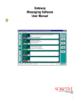
7Q8'&".#0)#"#()'"#$'"$53*0&)#0*
7Q878'='0"b.#6'%OO'0R)'("*.#6'(%i)!']C??'K:E9@?'7Q87^
Procedure:
- Disconnect the power cord of the analyzer and the possible printer interconnection cable
- Loosen the screws (1) and remove the casing cover. To open the maintenance door (2) remove only the
screws (10).
7Q8P8'='O+%a=()++
7YZQ[
The quartz-steel flow-cell (a patent) has been designed to heat quickly and to maintain with a high degree of
precision thermic equilibrium inside the cell.
The temperature is electronically controlled by a Peltier effect.
A solid state thermometer is incorporated inside the flow-cell, allowing the measurement of its temperature.
O+%a=()++''O)"0 3!)*
- volume: 50 µl
- optical path length: 10 mm
- optical axis (Z): 7.5 mm
- weight: 10 g
O:E87Q8P
1 flow-cell inlet
2 flow-cell outlet
3 thermometer probe
4 quartz window
5/6 temperature sensor 18720/22
7 clamping screw
Service Manual Autohumalyzer 900S Plus
54/84
7Q8P87'='(+)"#.#6'%O'0R)'O+%a=()++
At the end of a work-cycle, the flow-cell is automatically washed. To avoid the f ormation of bacterial growth
inside the flow-cell, it is advisable to wash the f low-cell at least once a week using a good laboratory glassware
detergent.
PROCEDURE
-Switch-on the instrument and dip the aspiration probe into the liquid detergent.
-Press the MANUAL PUMP pushbutton f or at least 10 seconds and leav e the solution in the flow-cell with
distilled water f or at least 15-20 minutes in order to remove any residues from the washing solution.
''O:E8'7Q8Q
1 flow-cell
17830
2 temperature sensor connector
3 Peltier
17820/20
4 Peltier connector
5 mounting screw
6 flow-cell clamping
7 stop pin
8 mounting block
9 preamplifier 18720/29
10 preamplifier connector
11 heat sink
Service Manual Autohumalyzer 900S Plus
18720/22
55/84
Service Manual Autohumalyzer 900S Plus
56/84
7Q8P8P'='O+%a=()++'!)1+"()&)#0'(see figure 13.3)
Procedure:
- Turn-off the analyzer and open the maintenance door (see par. 13.1)
- Remov e the inlet and outlet tubes f rom the flow-cell.
- Loosen the screw (6) and pull the cuvette upwards taking care not damage the thermometer wires.
- Loosen the clamping screw (7) and remove the thermometer (do it gently).
- Bef ore inserting the new flow-cell, spread a bit of thermal grease into the thermometer housing and secure it
(make sure that the thermometer fits perf ectly in its housing).
- Spread a bit of thermal grease on the side of the flow-cell that touches the Peltier device.
- Bef ore re-inserting the flow-cell, make sure that it is perf ectly clean inside, as well as the quartz windows on the
outside.
- Pull the screw (6) and re-insert the flow-cell (if correctly inserted the upper edge of the flow-cell is about at the
same height of the Peltier).
- Reconnect the tubes with their sleev es onto the flow-cell .
- Check the alignment by 'PHOTOMETER AND FILTER TEST' diagnostic program.
7Q8Q'='1R%0%&)0)!'+"&1*'!)1+"()&)#0'"#$'"+.6#&)#0''7YZP[2QP
(see figure 13.4)
Procedure:
- Turn-off the analyzer and open the maintenance door (see par. 13.1)
- Disconnect the lamp f rom the Photometer Interf ace PCB and loosen the clamping screw (5).
- Turn the vertical alignment screw (3) and remove the lamp (be caref ul not loose the spring).
- Carry out the same procedure to remove the second lamp.
- Insert the new lamps and the vertical alignment screws without tightening them (M?`F@?' ND' >D<' <D9BJ' <J?
E;FCC'TF@<'`:<J'VD9@'K:>E?@C, use the plastic envelope to hold the glass part of the lamps). Reconnect one lamp
to the Photometer Interf ace PCB.
- Turn-on the analyzer, set the service program and select the "Photometer and filters test".
- By means the manual pump fill the flow-cell with distilled water (make sure the flow-cell is free of air bubble).
- Select the filter 340nM (filter N° 0) and wait until the photometer starts measuring. It will show continuously the
mean absorbance between 7-8 readings.
- The monitor will be displaying continuously a number in mABS which must be minimised (the lamp must be
aligned both horizontally and vertically). Turn the screws f or the horizontal (4) and vertical (3) alignment until the
absorbance reaches the minimum value then tighten the clamping screw (5)
- Repeat the same procedure to align the second lamp.
- Select the lamp with the greater absorbance and adjust PR5 on A00749.01 board (ADC-DMA) to read an
absorbance around 130-150 mABS.
Service Manual Autohumalyzer 900S Plus
57/84
- Select the other filters, their absorbance must be between 100 and
300 mABS.
- Select the lamp with the smaller absorbance and turn the horizontal screw (4) to obtain the same value given
from the lamp previous aligned.
- Close the maintenance door.
7Q8Q87'='O.+0)!*')\3"+.-"0.%#']C??'K:E9@?'7Q8S^
#%0 )H bef ore to equalise the interf erence filters carry out the f ollowing maintenance operations
- cleaning of the optical system (lens, filters, quartz
windows)
- check of the flow through the flow-cell
- replacement of the lamps
- alignment of the lamps
Procedure:
- Fill the flow-cell with distilled water (make sure the flow-cell is f ree of air bubble).
- Adjust the 340 nm filter absorbance around 130-150 mABS (turn PR5 on ADC-DMA PCB).
- Select the other filters and note their absorbance. If one or more filters are outside the specified range it is
necessary to equalise them.
- Turn-off the analyzer and remove the cover panel (see par.3.1)
- Remov e the screw (10) and take the panel whit the chopper motor off.
- Loosen (half turn) the two Allen screws holding the filter wheel to the motor shaft and remove the filter wheel.
- One at a time remove those filters were the absorbance is outside the specified range (take care don't loose
the attenuators diskettes 17850/10).
- If the absorbance of the removed filter is below 100 mABS add one or more absorbance diskettes, if it is above
300 mABS subtract so many diskettes as necessary.
#%0 )H'HUMAN provides attenuators diskettes of 60,100 and 350 mABS. Take account that the real value of the
diskette change with the filter wav elength. For this reason a 100 mABS diskette added at the 405 nm filter will
increase the absorbance about 100 mABS while if added at the 620 nm filter will increase the absorbance about
50 mABS.
- Re-assembly the filter wheel and the chopper panel then switch-on the analyzer.
- Check the absorbance of each filter and if the test does not meet the specification repeat the procedure as
many times as necessary.
- Switch-off the analyzer and replace the cover panel.
Service Manual Autohumalyzer 900S Plus
58/84
7Q8S8'='1)!.*0"+0.('13&1*'034)'7ZZP[2U'!)1+"()&)#0'"#$'"$53*0&)#0
7Q8S878'='O+%a=()++'1)!.*0"+0.('13&1']C??'K:E9@?'7Q8U^
Procedure:
- Turn-off the analyzer and open the maintenance door (see par.13.1)
- Remov e the screws (4) and the tube holder (5).
- Replace the tube (3) with the new one having the same size and diameter (see note below).
- Replace the tube holder (5) and tighten the two screws (4) (take care don't pinch the tube)
- Turn-on the analyzer, set the service program and select the "Pump Test" Diagnostic Program (see par.1.6).
- Press key "1" to select the flow-cell peristaltic pump.
- Disconnect the aspiration tubing from the aspiration probe.
- Fill a graduate tube with 10ml of distilled water.
- Dip the photometer tubing into the graduate tube.
- Digit 10000 µl and press Enter twice.
- The pump has to aspirate10ml of water in about 40 seconds. If the test does not meet the specification, adjust
the volume
Service Manual Autohumalyzer 900S Plus
59/84
"$53*0 &)#0 H' Insert a small flat screwdriv er into the housing of the trimmer volume adjustment (6), turn it cw
to increase the v olume. After the adjustment check the volume again.
- Reconnect the photometer tubing to the aspiration probe and close the maintenance door.
7Q8S8P8'='a"*R'*,*0)&'1)!.*0"+0.('13&1*'7ZZS[2X
For these three peristaltic pumps used to draw in wash solution and waste, the procedure is identical to the
previous one. The three pumps are located under the keyboard. No adjustment is required.
#%0 )H THE SILICON TUBING USED IN THE PERISTALTIC PUMPS HAS TO BE OF THE PARTICULAR
TYPE, SUPPLIED BY CRONY. OTHER TUBING COULD ALTER VOLUMES ASPIRATED AND W ILL CAUSE
INCONVENIENCES IN THE PHOTOMETRIC MEASUREMENT.
O:E8'7Q8U
1
2
3
input
output
pump tube
Service Manual Autohumalyzer 900S Plus
4
5
6
screw
tubing holder
trimmer speed adjustment
60/84
7Q8U'='$.+30)!'
7YZS[2Q
7Q8U878'='*,!.#6)'!)1+"()&)#0']*??'K:E87Q8X^
Procedure:
- Loosen the syringe mounting screws (4) and (5).
- Remov e the syringe f rom the diluter panel and separate it (2) f rom the holder (6).
- Reconnect the new syringe and piston to the diluter panel (Make sure to fit the o'ring (3).
- Tighten the screws (4) and (5).
''''''''''''''''''''''''''''''''''''''''''''''''''''''O:E87Q8X
1
2
3
4
piston
syringe body
o'ring
syringe mounting screw
Service Manual Autohumalyzer 900S Plus
5
6
7
8
syringe holder mounting screw
syringe holder
tube fitting
tubing
61/84
7Q8U8P'='4)+0'!)1+"()&)#0'"#$'"$53*0&)#0']C??'K:E8'7Q8Y^
PROCEDURE:
- Open the maintenance door (see par. 13.1).
- Disconnect the tubes and remove the syringe.
- Remove the four screws that fix the assembly to the chassis.
- Loosen the Allen screw (22) and remove the encoder disk (14).
- Take the belt (13) off and place the new one.
- Replace the encoder disk (14).
- Tighten partially one of the two screws that hold the syringe in the upper hole.
- By means the diagnostic program carry out the homing of the diluter.
- By means a calliper check the distance between the screw and the mechanical part (17). The requirement is
106.5 mm +/- 0.1mm.
If the check does not meet the specification, loosen the Allen screw (22) and turn the encoder disk (14) cw to
increase the distance or ccw to reduce it then tight the screw (22).
- Re-assembly the syringe, connect the tubes and fix the module to the chassis.
- Close the maintenance door.
7Q8U8Q8'='$.+30)!'&".#0)#"#()
Ev ery 5 or 6 months place a bit of lubricating grease on the mechanical screw of the diluter. Have it done by your
service engineer during the periodic visits.
Service Manual Autohumalyzer 900S Plus
62/84
Service Manual Autohumalyzer 900S Plus
63/84
7Q8X'='a"*R.#6'a)++'7YZP[2Y'(+)"#.#6
Clean the washing well periodically (once a month) with a diluted bleach solution 1:5, by pouring some of that
bleach solution into the well. Leave the bleach solution inside f or 15 to 20 minutes. W ash well thereafter.
O:E8'7Q8Z
7Q8Y'=''/'=','='-'"/)*']C??'K:E87Q8j^
#%0 )H W hen there is not the right timing between the homing and the sync signals, a mechanical position error
takes place. This event may be caused f ollowing a hardware f ailure (motor, optical sensor, rubber belt, PC
board) or a mechanical misalignment. In any case it is necessary to carry out this adjustment to restore the
regular operating conditions.
7Q8Y87'='1!%4)*'()#0)!.#6
Procedure:
- Turn-off the analyzer and remove the casing cover (see par.13.1)
- Remov e the reagent and sample racks.
- Disconnect the two tubings f rom the liquid sensors.
- Remov e the work plane of the analyzer.
! Loosen the Allen screw (1) holding the rubber belt (2) in order to unclamp the
x-axis movement.
- Loosen the Allen screw (3) holding the rubber belt (4) in order to unclamp the y-axis movement.
- Manually mov e z-axis assembly (6) outside its standby position.
Service Manual Autohumalyzer 900S Plus
64/84
- Turn-on the analyzer; when the x-y stepper motors begin to run move the z-axis assembly (6) toward the
standby position. If the action is successf ul, the coincidence of the two signals Homing and Sync stops
immediately the stepper motors in the standby position.
- Tighten the Allen screws (1) and (3) W ithout moving the z-axis assembly.
- Make a mechanical reset of the analyzer and check the probes centring. Repeat the adjustment if necessary.
O:E87Q8j
1 x-axis set screw
2 x-axis rubber belt
3 y-axis set screw
4 y-axis rubber belt
5 z-axis set screw
6 z-axis assembly
7 encoder wheel
Service Manual Autohumalyzer 900S Plus
65/84
7Q8Y8P'='-''"/.*'"+.6#&)#0']*??'K:E87Q8j^
#%0 )H W hen the z-axis motor or the rubber belt or the EB0091.01 PC Board are replaced and every time the
wheel (7) is removed it is necessary to carry out this adjustment.
Procedure:
- Turn-off the analyzer and remove the casing cover (see par.13.1).
- Turn-on the analyzer and set the service program.
- check the crank (1) of the z-axis assembly (see fig 13.11),in standby condition it must be perpendicular respect
to the analyzer baseplane, if it is not , loosen the Allen set screw (5) half turn.
- If the crank is mov ed toward the mixer probe, turn the wheel (7) slightly ccw. Instead if the shaf t is moved
toward the sampling and aspiration probes turn the wheel slightly cw.
- Tighten the Allen set screw (5) then check the Z-axis assembly by means the diagnostic program (perf orm a
mechanical reset of the instrument).
- If the check is not satisf actory repeat the alignment.
- Turn-off the analyzer and re-assembly the casing cover.
O:E87Q87[
1 crank
2 probe slide
3 mixer
18820/10 mixer blade, 18820/30 mixer motor
4 sampling probe
18820/4
5 reading probe 18820/3
Service Manual Autohumalyzer 900S Plus
66/84
7Q8Z'='0)&1)!"03!)'(%#0!%+'"#$'"$53*0&)#0
7Q8Z87 -'.#(34"0.%#'(R"&4)!
- Turn-off the analyzer and remove the casing cover.
- Turn-on the analyzer and set the service program.
- Place a reaction plate on the reaction well and fill a cell with distilled water.
- Select 25°C temperature and dip the thermometer probe inside the cell.
- W ait f or 15-20 minutes and check the thermometer: The read temperature must be 26°C +/- 0.1°C.
- If the check does not meet the specification adjust PR8 on Power Supply PC Board (turn ccw to increase the
temperature).
- Check the temperature at 30°C and 37°C and adjust according to the below table.
0)&1)!"0 3!)
"$53*0 &)#0
*1)(.O.("0.%#
PUm(
Q[m(
QYm(
1!Z
1!Y
1!X
01P7'''P8jZ'i
01P['''Q8[Q'i
017j'''Q87P'i
PXm('k2=''7m(
Q7m('k2=''7m(
Qjm('k2=''7m(
7Q8Z8P'= O+%a=()++
- Insert the temperature probe inside the hole (3) (see figure 13.2)
- Select 25°C temperature and wait f or 30 seconds.
- Check the thermometer: the read temperature must be 25°C +/- 0.1.
- If the check does not meet the specification adjust PR5 on Power Supply PC Board (turn ccw to increase the
temperature).
- Check the temperature at 30°C and 37°C and adjust according to the below table.
0)&1)!"0 3!)
"$53*0 &)#0
*1)(.O.("0.%#
PUm(
Q[m(
QYm(
1!U
1!S
1!Q
01PS'''78[['i
01PQ'''P8[['i
01PP'''Q8S['i
PUm('k2='[87m(
Q[m('k2='[87m(
QYm('k2='[87m(
- Turn-off the analyzer and re-assemble the casing cover.
7Q8Z8Q - !)O!.6)!"0%!'']C??'K:E9@?'7Q87U^
#%0 )H'this check must be carried out at a room temperature not greater of 25 °. (maximum rating room
temperature minus 15 °C)
- Fill a reagent container with distilled water and leave it in the ref rigerator compartment for at least 20 minutes.
- Insert the temperature probe inside the container and wait for 1 minute.
- Check the thermometer: the required temperature must be between 10 and 15 °C.
- If the check does not meet the specification adjust PR2 on EB0080.01 PC Board.
Service Manual Autohumalyzer 900S Plus
67/84
7Q8j8'='1!)i)#0.i)'&".#0)#"#()
It is recommended to schedule the prev entiv e maintenance operations at least twice a year.
"#$%&%'(&)*+!,-,&('
!'(J?BhC'`:<J'F>F;Vn?@'<9@>?N=DKK
!'Cleaning of the optical lens
!'Cleaning of the interference filters
!'Flow-cell check
-check of the flow
-cleaning of the quartz windows
!'Replacement of the lamps
!'(J?BhC'`:<J'F>F;Vn?@'<9@>?N=D>
! Check the filters wheel homing signal(5V)
!'Check of the lamp voltage (5.9V)
!'Alignment of the lamps (340nM filter selected)
!'Check of the absorbance
!'Check of the flow-cell temperature
.#/-0)123*+!,-,&('
!'Replacement of peristaltic pumps tube
!'Check/adjustment of pump aspiration volume
(once year)
!'Full tubes replacement (every two years)
!'Check of liquid sensors (waste and wash)
!'Replacement of the syringe piston
!'Check of the sensor lev el
!'Cleaning of the washing and waste wells
!'Check of the flow through the probes
4#!5(+617*+13!,-,&('
!'Check of probes centring in the waste position
!'Check and cleaning of Z axis mechanism
-cleaning of the two sliding axes
-cleaning of PC board
-cleaning of the two sliding contacts
!'Check, cleaning and lubrication of Y axis
!'Check of Z axis alignment
mechanism
!'Check of the probes positions in the reagent,
!'Check and cleaning of X axis mechanism
sample and reaction area
!'Check, cleaning and lubrication of dilutor
screw
! Check of back-up battery voltage
Service Manual Autohumalyzer 900S Plus
8#!9%7&)%3!,-,&('
! Check of CPU f an
68/84
Service Manual Autohumalyzer 900S Plus
69/84
Service Manual Autohumalyzer 900S Plus
70/84
Service Manual Autohumalyzer 900S Plus
71/84
Service Manual Autohumalyzer 900S Plus
72/84
Service Manual Autohumalyzer 900S Plus
73/84
Service Manual Autohumalyzer 900S Plus
74/84
Service Manual Autohumalyzer 900S Plus
75/84
7S8'='0!%34+)*R%%0.#6
7S878'='0@D9M;?CJDD<:>E'E9:N?
:;5<=>5
9?@:A:!?BC!DA5ACEA:
"#"+,-)!'$%)*'#%0
0 3!#=%#
-CHECK POW ER SUPPLY CORD IF INSERTED
-CHECK FUSES
-CHECK FOR PROPER VOLTAGE
1R%0%&)0)!'+"&1'.*
%OO
-CHECK POW ER SUPPLY BEFORE CHANGING LAMP
-IF COMPUTER AND INSTRUMENT ARE "ON" CHANGE LAMP
1!%6!"&'$%)*'#%0
+%"$
-TURN.OFFTHE ANALYZER, W AIT FOR 10 SECONDS THEN
TURN-ON AGAIN
1!.#0 )!'$%)*'#%0
0 3!#=%#
-MAKE SURE THAT THE POW ER CORD IS PLUGGED-IN
-CHECK ON/OFF SW ITCH
-CHECK FUSES
1!.#0 )!'$%)*'#%0
1!.#0
-MAKE SURE IT IS SET "ON LINE"
a"*R.#6'a)++'$%)*
#%0 'O.++
-MAKE SURE THERE IS W ASHING SOLUTION IN THE
CONTAINER
-MAKE SURE THAT THE PERISTALTIC PUMP IS OPERATING
PROPERLY
-CHECK CONNECTING TUBING TO THE W ELL
O+%a'()++'$%)*'#%0
O.++'1!%1)!+,
-CHECK PERISTALTIC PUMP FOR PROPER OPERATION
-CLEAN FLOW -CELL IT MAY BE DIRTY
-CHANGE ASPIRATION TUBING IT MAY BE TORN
-ASPIRATION TUBING TOO LONG OR TOO SHORT
1R%0%&)0)!'$%)*'#%0
!)"$
-CHECK IF THE PHOTOMETER LAMP IS ON
-TRY TO READ ON ANOTHER W AW ELENGTH
-CHECK IF CHOPPER IS TURNING
-CLEAN FLOW -CELL, IT MAY BE DIRTY
-TRY TO LUBRICATE THE SCREW W ITH A BIT OF
LUBRICATING GREASE
-CLEAN SYRINGE W ITH A GOOD LABORATORY DETERGENT
-CHANGE SYRINGE
$.+30)!'&%$3+)'*0%1*
$.+30)!'$%)*'#%0
"*1.!"0 )'%!'$.*1)#*)
-PINCHED OR TORN SYRINGE TUBING
-LOOSE OR BADLY CONNECTED SAMPLING PROBE
-BLOCKED SAMPLING PROBE; CLEAN OR REPLACE
-CHECK W ASH SOLUTION CONTAINER, FILL IF EMPTY
-CHECK THE O'RING ON THE SYRINGE
*,!.#6)'R"*'$.OO.(3+0 ,
.#'O.++.#6'%!')&10,.#6
-CHECK IF W ASH SOLUTION IS ENOUGH
-CHECK FOR LEAKING PISTON OR BLOCKED TUBING
-REMOVE SYRINGE AND CLEAN IT
a"0 )!'4+"#b'R"*'0%%
R.6R'"4*%!4"#()
-AIR BUBBLE IN FLOW -CELL
-REPLACE THE PHOTOMETER LAMP
-CHECK PHOTOMETER LAMP ALIGNEMENT
-CHECK W ASH SOLUTION AND W ASH FLOW -CELL
-CHANGE W AW ELENGTH AND TRY AGAIN; MAY BE A DIRTY
FILTER
-DIRTY OR OLD W ASH SOLUTION; PREPARE FRESH
Service Manual Autohumalyzer 900S Plus
76/84
!)*3+0'"!)'#%0
!)1!%$3(.4+)
"1.!"0 .%#'.#0%'O+%a=
()++'.*'#%0'(%#*0 "#0
-DIRTY REACTION PLATES; USE NEW ONES
-SPORADIC AIR BUBBLES IN FLOW -CELL; CLEAN FLOW -CELL
-CHECK ASPIRATION INTO THE FLOW -CELL, MAY BE TOO
CRITICAL
-USING TOO SMALL REAGENT VOLUME; INCREASE IT
-CHANGE PHOTOMETER LAMP
-DIRTY OR OLD W ASH SOLUTION
-BAD CONNECTION OR TORN ASPIRATION TUBE
-CHECK ASPIRATION PROBE FOR BLOCKAGE OR DIRT
-CHECK PERISTALTIC PUMP TUBING; IT MAY NEED
CHANGING
-CHECK THAT THE BOTTOM OF THE REACTION PLATES IS
PERFECT AND NOT DEFORMED
".!'4344+)*')#0)!.#6
O+%a=()++
-TORN OR IMPROPERLY CONNECTED TUBING BETW EEN
ASPIRATION PROBE AND FLOW -CELL
-ASPIRATION TUBING TOO LONG OR TOO SHORT FOR THE
TOTAL VOLUME OF REAGENT USED IN THE TEST
-MAKE SURE TO USE THE CORRECT CONNECTING TUBING
*)!3&'(%#0!%+*'#%0
a.0 R.#')/1)(0)$
!"#6)
-CHECK CONTROLS FOR EXPIRATION DATE
-CHECK METHOD; IT MAY HAVE BEEN INADVERTENTLY
REPROGAMMED
-MAKE SURE THAT METHOD CONFORMS W ITH REAGENT
SUPPLIERS SPECIFICATION
-RE-ASSAY BY AN ALTERNATE SYSTEM OR METHOD
-CHECK TEMPERATURE BOTH INCUBATION AND ASPECIALLY
FLOW -CELL; TRY ANOTHER REAGENT OR CONTROL
$.+30)!'*,!.#6)'$%)*
#%0 '&%i)'31'"#$'$%a#
!)63+"!+,
-PLACE A BIT OF LUBRICATING GREASE ON THE SCREW AND
RESTART
-DIRTY SYRINGE: CLEAN OR REPLACE
-DIRTY PISTON: CLEAN OR REPLACE
*,!.#6)'+)"b*
-CHECK THE PISTON
-CHECK THE O'RING ON THE SYRINGE
-CHECK THE OUT-TUBING FOR BLOCKAGE
-MAKE SURE SAMPLING PROBE IS NOT BLOCKED
-CHANGE SYRINGE AND PISTON
-MAKE SURE THE PISTON IS TIGHT AND THERE ARE NO
LEAKS
-PUT SOME TW EEN 20 INTO THE W ASH SOLUTION (ONE
DROP PER 1 LITRE OF DISTILLED W ATER)
-MAKE SURE THAT THE INLET CONNECTION TO THE SYRINGE
IS TIGHT
-CHECK IF THE INLET TUBING IS TORN
0 R)!)'"!)'4344+)*
.#*.$)'0 R)'*,!.#6)
*"&1+)*'"!)'4).#6
(%#0 "&.#"0 )$
-SAMPLING PROBE IS LEAKING OR BADLY CONNECTED
-CHANGE PROBE OR CLEAN IT PROPERLY
-CLEAN W ASHING W ELL
-MAKE SURE THAT THE W ASTE IS PROPERLY ELIMINATED
-MAKE SURE THAT THE W ASH SOLUTION IS FRESHLY
PREPARED AND NOT DIRTY
-W ASH FLOW -CELL W ITH A DETERGENT SOLUTION
.#(34"0 .%#'4+%(b'.*
#%0 'R)"0.#6'1!%1)!+,
-CHECK THE PROGRAMMED TEMPERATURE, IS IT ACTUALLY
PROGRAMMED TO 37°C?
Service Manual Autohumalyzer 900S Plus
77/84
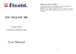
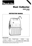
Check filter values displayed
to find out which filter is
above the value of 400
aF<?@'M;F>h'?@@D@
G?CCFE?
1. value =
340 nm
2. value =
405 nm
3. value =
492 nm
4. value =
510 nm
5. value =
535 nm
6. value =
546 nm
7. value =
578 nm
8. value =
620 nm
(J?Bh `J?<J?@ '`F<?@'`FC FCT:@F<?N '<D'<J?
K;D`'B?;; F>N'<J? ;FGT':C'D>
Go to the diagnostic program
(SHIFT & ALT & CTRL & D)
Select 1: Photometer test and check all filters,
the displayed absorbance value must be
between 100 and 400 for all filters with
destilled water in the flowcell
Replace lamp and adjust it at
340 nm to a value of 100 to 200,
use destilled water in the
flowcell
,)*
Exit the
diagnostic
All values in
range
(100 - 400)
#%
#%
Check lamp voltage at lamp
to be 6 V, adjust on power
supply PCB if wrong
All filters except 340 and
405 nm are below 100
Check whether the flow cell
is clean
Replace the 340 nm and / or
405 nm filter
Adjust PR5 on ADC/DMA
PCB until 340 nm is in range
Replace the filter which is
out of range
Service Manual Autohumalyzer 900S Plus
78/84
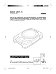
!"#$%&'()*(#!'$#+ "' ,'%-
#%
Air bubbles
in the flow
cell ?
,)*
Clean the washing well
Is the wash water
container full ?
Are the reaction plates
Check w hether the line
clean and new ?
to the dilutor syringe is
filled
Is the mixer working ?
Check heigth of
needles in reaction well
Use fresh reagent and
samples
Check for leakage in
the aspiration system
Verify the method
settings
Adjust speed of cuvette
pump
Check temperature of
flow cell
Check ADC/DMA PCB
Check preamplifier
Check position of filter
wheel (optical sensor)
Service Manual Autohumalyzer 900S Plus
79/84
7S8P'='RF@N`F@?')@@D@C
If during the analyzer working, a wrong position of the mechanical assembly takes place, on the screen will be
showed one of the f ollowing error code. On end there is the list of more common error codes with their meaning.
(DN? &?CCFE?
&?F>:>E
7[PS
ATTENTION: Positioning
error X during motion.
W rong positioning of X axis during the movement
7[ZZ
ATTENTION: Positioning
error X during motion to
home.
W rong positioning of X axis when back home
P[SZ
ATTENTION: Positioning
error Y during motion
W rong positioning of Y axis during the movement
P7YX
ATTENTION: Positioning
error Y during motion to
home
W rong positioning of Y axis when back home
QPXS
ATTENTION: Positioning
error X during motion to
home, Y during motion to
home.
W rong positioning of X-Y axes when back home
S[jX
ATTENTION: Z status:
10
Transmission error between the CPU Pentium and the micro
device of Z axis. This error is caused at 99% f rom the friction
between the two probes and the sliding axes. W ith less
probability, could be caused from the breaking of the flat cable
FC0010.01
S[jY
ATTENTION: Z status:
10
Transmission error between the CPU Pentium and the micro
device of Z axis.
S[jj
ATTENTION: Positioning
error Z status NO
response
Transmission error between the CPU Pentium and the micro
device of Z axis. This error is caused from the software stop of Z
axis micro device and very seldom f rom the breaking of the flat
cable FC0010.01
Service Manual Autohumalyzer 900S Plus
80/84
7U8'*1"!)'1"!0*'"#$'"(()**%!.)*
7U878'='"(()**%!.)*''R3&"#'(F<8=#D8'7YZ[[27
HUMAN Cat.-No
18720/50
18720/17
18270/3
18720/4
18720/27
17820/32
Description
SAMPLE CUPS (PKG OF 250 CUPS)
REACTION PLATES (PKG OF 25 FOR 750 TESTS)
CYLINDER & PISTON N°4
REAGENT CONTAINER (32ML)
ASPIRATION PROBE
SAMPLING PROBE
REAGENT CONTAINER (16ML)
PHOTOMETER LAMP
7U8P8'='*1"!)'1"!0*
HUMAN Cat.-No.
17800/2
17800/3
17800/4
17810/10
17810/11
17810/12
17810/13
17810/2
17810/20
17810/5
17810/6
17810/7
17810/8
17810/9
17820/1
17820/11
17820/12
17820/13
17820/14
17820/15
17820/16
17820/2
17830
17840/3
17840/4
17840/5
17840/6
17850/10
17850/13
17860
1820/29
Description
User Manual 900 S Plus
Service Manual 900 S Plus
Product Manual 900 S Plus
VOLTAGE REGULATOR
TRANSFORMER 350 VA
POW ERSUPPLY ASSEMBLY COMPLETE
PLUGS AND BRAKER ASSEMBLY COMPLETE
MICROPROCESSOR PENTIUM 100 Hz
MONITOR LCD 640 x 480
586 ISA BUS COMPUTER
SIMM 4Mb
6 SLOT ISA-BUS PASSIV BOARD
INVERTER FOR LCD
+5/+12V SW ITCHING POW ER SUPPLY
MICRO FAN
REAGENT SECTOR
SAMPLE RACK 1-30
SAMPLE RACK 31-60
UNDERFLOW PLUG
OVERFLOW PLUG
W ASTE W ELL
24V/65W SW ITCHING POW ER SUPPLY
FLOW -CELL 50 UL
DILUTER ASSEMBLY
PHOTOMETRIC ASSEMBLY
REFRIGERATOR MODULE
PELTIER AND THERMOMETER FOR REFRIGERATOR
ATTENUATORS DISKETTES SET
POW ER SUPPLY FILTER
FLAT CABLE SET
PREAMPLIFIER ASSEMBLY
HUMAN Cat.-No.
Description
Service Manual Autohumalyzer 900S Plus
81/84
18710/1
18710/10
18710/11
18710/12
18710/13
18710/3
18710/4
18720/13
18720/18
18720/20
18720/21
18720/22
18720/29
18720/30
18720/31
18720/50
18720/62
18720/7
18720/8
18720/9
18730/1
18730/3
18730/4
18740/1
18740/2
18740/3
18750/1
18750/14
18750/3
18750/4
18750/5
18750/6
18750/7
18750/8
18750/9
18760/2
17810/1
18810/10
18810/11
18810/12
18810/4
17810/50
18810/6
18810/7
18810/8
18810/9
18820/10
18820/14
KEYBOARD
PRINTER
PRINTER CABLE
PRINTER PAPER
Printer Ribbon
LOUDSPEAKER
FLOPPY DISK DRIVER 1,44Mb 3,5"
X-Y OPTORECOVER BOARD
HEATING RESISTANCE 48V/50W
PELTIER
TEMPERATURE SENSOR TS1(incubator)
TEMPERATURE SENSOR TS2 (flowcell)
Preamplifier Assembly
REACTION PLATE (100 pcs.)
SAMPLE CUPS (2000 pcs.)
Syringe & Piston for Dilutor
Piston for Syringe
ADC-DMA BOARD
PREAMPLIFIER BOARD
Driver & Control Stepper Motors
QUARTZ LENS F=24
Motor X - Axis
Motor Y - Axis
POW ER SUPPLY CABLE
Flat cable X-axis (W4)
Flat cable Y-axis (W11)
FILTER 340NM
FUSE
FILTER 405NM
FILTER 492NM
FILTER 510NM
FILTER 535NM
FILTER 546NM
FILTER 578NM
FILTER 620NM
O-Ring for Syringe
HARD DISK DRIVER 4.3 GB
STEP MOTOR DRIVER BOARD
Z-AXIS BOARD
Peristaltic Pump Board
Computer Power Supply
I/O PORTS Version 2
X-Y-Z AXES DRIVERS BOARD
X-Y-Z INTERFACE BOARD
Opto Dilutor Board
PHOTOMETER INTERFACE BOARD
Mixer Blade
Tubing Kit complete
HUMAN Cat.-No.
18820/15
18820/16
18820/17
Description
W ATER CONTAINER
W ASTE CONTAINER
Reagent Container 32ml
Service Manual Autohumalyzer 900S Plus
82/84
18820/22
18820/23
18820/27
18820/3
18820/30
18820/4
18820/5
18820/6
18820/7
18830/1
18830/10
18830/11
18830/2
18840/1
18840/10
18840/11
18840/12
18840/2
18840/4
18840/6
18840/6
18840/7
18840/8
18840/9
18850
18850/1
18850/2
18850/3
18850/4
18860/2
Sensor Wash Solution
Sensor Waste Container
Reagent Container 16ml
Aspiration Probe
Mixer Motor
Sampling Probe
Tubing Peristaltic Pump (4 pcs.)
Adapter for Sample Cups
W ASHING W ELL
Mixer holder
Mounting block for flowcell
Spring loaded screw for flowcell
Probes holder
X-Y-Z ASSEMBLY
Motor for Filterwheel
PERISTALTIC PUMP FOR W ASTE/W ATER
Motor Z - Axis
INCUBATION CHAMBER ASSEMBLY
Photometer Assembly
PERISTALTIC PUMP FOR DILUTER
Peristaltic Pump for Dilutor
Chopper Motor
PERISTALTIC PUMP FOR FLOW -CELL
Motor for Peristaltic Pump Flow Cell
Revolver with 8 filters
Flat Cable Set
Sensor Cable
Extension cable probes to Z-Board
Sliding contact for probes
Hinges for Cover (2 pcs.)
List of micro-programmable devices
HUMAN Cat.-No.
17850/1
17850/2
17850/3
17850/4
17850/5
Description
Photometer interf ace
Z-axis control
Power supply
XYZ interface control
Pump board
Service Manual Autohumalyzer 900S Plus
Device
ST62T10
ST62T10
16C711
PALCE22V10H
GAL16V8
Board
EB0114.02
EB0145.01
EB0080.01
EB0083.01
EB0121.01
Layo. Ref .
U2
U1
U9
U1-U2
U2
83/84
!"#$%"&!'()*+,-..,/,
0123
,0456,7863
R3&"#
7YZ[P
7
7YZ[7
7
&F:><?>F>B?'b:<
2 X Photometer Lamp
1 X Aspiration Probe
1 X Sampling Probe
1 X O-Ring for Syringe
1 X Piston for Syringe
1 X Syringe with Piston
1 X Mixer Blade
1 X Tubing Kit complet
1 X Grease & Oil
*<F@<?@'*TF@?'1F@<'b:<
1 X Service Manual
1 X User Manual
1 X Keyboard
1 X Peltier Element
1 X Temperature Sensor TS1
1 X Temperature Sensor TS2
1 X Flow Cell
1 X Fuse Box (10 pieces)
1 X Filter 340nm
1 X Filter 405nm
6 X Photometer Lamp
1 X Syringe with Piston
1 X Piston for Syringe
5 X O-Ring for Syringe
1 X Harddisk Drive with Software
1 X Peristaltic Pump Board
1 X Peristaltic Pump for Flow Cell
1 X Aspiration Probe
1 X Sampling Probe
5 X Mixer Blade
1 X Mixer Motor
1 X Sensor Wash Solution
1 X Sensor Waste Bottle
1 X Tubing Peristaltic Pump (4 pieces)
1 X Sensor Cable
1 X Flat Cable Set
#%0 )H'.#O%!&"0 .%#'(%#0 ".#)$'.#'0 R.*'&"#3"+'.*'0R)'1!%1)!0 ,'%O'R3&"#'6GMR'6?@GF>V8
!)1!%$3(0.%#'%O'"#,'1"!0'%O'aR%+)'&",'4)'$%#)'a.0R'a!.00)#'1)!&.**.%#'O!%&'R3&"#
6GMR8
Service Manual Autohumalyzer 900S Plus
84/84
Human
Gesellschaft für Biochemica
und Diagnostica mbH
Max-Planck-Ring 21 ! D-65205 Wiesbaden
Germany
Telefon:
+49 6122 9988 0
Telefax:
+49 6122 9988 100
eMail:
Internet:
01/2004-04
[email protected]
http://www.human.de