1
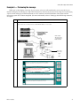
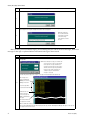
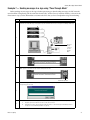
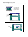
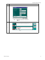
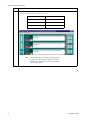
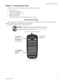
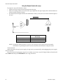
Gateway
Messaging Software
User Manual
Copyright © 2000 Adaptive Micro Systems
Form No. 9711-8808A
11/03/00
i
NOTE:
Due to continuing product innovation, specifications in this document are subject to change without
notice.
Copyright © 1999 - 2000 Adaptive Micro Systems, Inc. All rights reserved.
The distinctive appearance of this product is a Trade Dress of Adaptive Micro Systems, Inc.
BetaBrite, BETA-BRITE, BIG DOT, and SMART ALEC are trademarks of Adaptive Micro Systems, Inc. registered in the United States Patent and
Trademark Office.
ADAPTIVE, Alec, ALPHA, AlphaLert, AlphaNET, AlphaNET plus, AlphaNET plus II, ALPHAVISION, Automode, BetaBrite Director, EZ KEY II, EZ95,
PagerNET, PPD, PrintPak, Solar, and TimeNet are trademarks of Adaptive Micro Systems, Inc.
Visit our Internet World Wide Web site:
http://www.adaptivedisplays.com or e-mail us at [email protected]
ii
Gateway Messaging Software Manual
Table of Contents
General information
1
Purpose of the system ................................................................................... 1
Setting up the ALPHA sign network ................................................................2
Basic software setup .................................................................... 5
File usage ........................................................................................................5
Screen layout reference.................................................................................. 5
Setting the serial port ..................................................................................... 7
Setting message size and maximum messages ............................................. 8
Basic messaging ........................................................................ 10
Example 1 — Creating a simple message .................................................... 10
Example 2 — Making a message flash..........................................................15
Example 3 — Setting message priorities ..................................................... 17
Example 4 — Deleting messages................................................................. 18
Example 5 — Checking message syntax...................................................... 20
Example 6 — Previewing the message ........................................................ 23
Example 7 — Sending messages to a sign using “Pass-Through” Mode .... 25
Advanced messaging .................................................................. 28
Example 8 — Setting the background message........................................... 28
Example 9 — Inserting objects: date, time or special characters ..................30
Synchronizing your sign’s date and time with a PC .............................30
Adding a date to a message .................................................................31
Adding special characters from the extended character set .................32
Adding time to a message....................................................................33
Example 10 — Creating and inserting variables ...........................................34
Example 11 — Using the Remote Control ....................................................37
Appendices .............................................................................. 42
Appendix A: Sending priority messages from a PLC ....................................42
Appendix B: Frequently-Asked Questions .....................................................44
Table of Contents
iii
Gateway Messaging Software Manual
iv
Table of Contents
Gateway Messaging Software Manual
General information
Purpose of the system
An ALPHA Gateway interface connects Programmable Logic Controllers (PLCs) with ALPHA series signs
that have the Industrial Gateway firmware upgrade. It provides the ability to display user-defined real-time
messages. The Gateway Messaging Software allows you to create and edit messages on a computer and transfer them
as a group to the ALPHA signs. Messages can then be displayed on the signs when triggered by PLCs via the
Gateway device.
Gateway Messaging Software (up to version 1.5b) has been
used with ALPHA Gateway devices configured for serial
connection (see drawing, left).
Serial-connected
GATEWAY
Device
Gateway Messaging Software (versions after 1.5b) is used
with a different family of ALPHA Gateway interfaces (see
drawing below left), that feature DIN-rail mounting and several
different 3-module configurations, each specifically designed to
interface with a single type of network.
2 25-pin Serial
Connections
NOTE: Specific PLC
interface (such as
DN3000, PD3000,
or MB3000) needed.
These are marked
clearly on the front
of each unit.
NOTES:
1.
When Gateway Messaging Software is used with one of
the DIN-rail mounted interfaces (shown below, left) to
trigger and display messages on an ALPHA sign
network, through the local PLC network, you must
follow a device-specific install procedure.
•
NOTE—Refer to Form Number
97ø3-7øø4C if you have the serialconnected GATEWAY interface
shown above, the preceding edition
of this manual.
Communications Module
2.
For specific network set up and installation
procedures, refer to the Table of Gateway Network
Installation Instructions, Page 3.
To use Gateway Messaging Software to program
messages that will be displayed on your ALPHA sign
network, you do not have to be connected to the local
PLC network. Gateway Messaging Software can be used
before your ALPHA network has been completely
installed and fully integrated into the PLC network
since all messages are created through the software and
stored in each sign’s memory, whether or not the PLC
network interface has been installed (see step 1, above.)
Power Supply Module
Network Interface Module
DIN rail mounting
Typical 3-module ALPHA
Gateway Interface—for Gateway
Messaging Software versions
after1.5b. Specific connections
for the 3 individual modules, left
to right, may vary according to
network configuration and
installation environment. Refer to
the Table of Gateway Network
Installation Instructions on Page
3 for data on your particular
network.
General information
1
Gateway Messaging Software Manual
Setting up the ALPHA sign network
The following briefly describes the first step in setting up and installing required hardware in the PLC
network, configuring the signs for the ALPHA network and making required connections to begin using Gateway
Messaging Software. Configurations and specific components required will vary according to the specific ALPHA
Gateway Interface, which will be specific to the local PLC network.
Step
Description
Although you do not need to complete full installation of the Gateway interface on the PLC network to begin to use Gateway Messaging
Software, you should connect the sign network (or at least one “starter” sign) through an RS485 connection, to begin the process of
creating, storing, and sending messages:
•
Install Gateway Messaging Software on a PC
•
Connect the PC to the RS232 jack in the ALPHA Gateway interface CPU module
Refer to the Network Configurations manual (97ø8-8ø46)for additional info on sign network installations and routing RS485 cable.
ALPHA/Gateway RS485 serial network
G
F
E
1
NOTES: Gateway
Messaging Software
operates through an
RS232 connection..
D
A
C
B
See Related Documents (below) and Table of Gateway Network Installation Instructions (next page) for more information.
Item
2
Part Number
A
contact Adaptive
B
1088-9108/1088-8625
C
—
2
CD with Gateway Messaging Software installed on PC
DB9 to RJ11 adapter / RS232 25 foot cable w/2 RJ11 jacks (50 ft. cable opt.)
Specific Gateway network interface for local network
D
1088-8000
RS485 cable (bulk, 1000 foot)
E
1088-8624
8 foot RS485 cable (typical, or other standard length)
F
4331-0602
Modular network adapter (s)
G
1088-9107
End of line terminator for TTL plug of last sign in the network.
Related Documents
3
Description
Network Configurations
Part number
Description
9708-8046A
Explains how to network ALPHA signs.
NOTE: For specific information on routing long distance
RS-485 network connections, see Appendix G of the
Network Configurations manual.
General information
Gateway Messaging Software Manual
Step
Description
Connect the same color wires from each RS485 cable to the same screws on the adapter.
Modular network
adapter wiring
connections
+ RS485 (black) to BK screw
Shield wire to RD screw
–
4
RS485 (red) to YL screw
+
RS485 (black) to BK screw
–
RS485 (red) to YL screw
Shield wire to RD screw
In order to install the network-specific ALPHA Gateway interface on the local network and complete required PLC programming for the
Gateway network, refer to the table below for your specific Gateway interface.
Table of Gateway Network Installation Instructions
Part Number
5
Title
9711-88ø9
How to configure and connect the ALPHA Gateway II interface to a DeviceNet network.
9711-881ø
How to configure and connect the ALPHA Gateway II interface to a Profibus DP network.
9711-8811
How to configure and connect the ALPHA Gateway II interface to a Modbus Plus network.
9711-8812
How to configure and connect the ALPHA Gateway II interface to a DataHiway Plus network.
97ø8-8046*
Network Configurations (*For information on RS485 cabling see Appendix G)
NOTE: Additional installation documents, information and examples for programming the PLC may
be available on the Adaptive website,
www.adaptivedisplays.com
with Gateway firmware
6
It is not necessary to complete the previous step in order to setup the ALPHA network and begin to create, edit, preview and store
messages on the sign network. using the Gateway Messaging Software. If you’re setup of the ALPHA network is complete, you can skip
to the section on “Basic messaging” on page 10 and “Advanced messaging” on page 28 for more information.
NOTE: Perform this step (6a) after all signs in the network that will be receiving messages have been connected to the ALPHA network
and to the computer, through the ALPHA Gateway interface.
6a
General information
Once you have created your messages using the Gateway Messaging Software, you are ready to transmit those messages to all of the
signs in your network. If more than one sign is networked, all signs will receive the messages. (Please refer to “Example 1 — Creating a
simple message” on page 10 for information on completing this step.)
3
Gateway Messaging Software Manual
Step
Description
NOTE: Perform this step (6b) only if a sign is added to the sign network after the initial setup.
Connect the new sign to the network. Using a Remote Control, transmit the messages from one of the signs in the ALPHA network to the
newly-connected sign. (Refer to page 41, Remote Control Special + D option for more instructions.)
• Set Serial Address
• Use “Special + D”
command to transfer
messages.
• See page 41, Remote
Control Special + D
option
6b
RS485
PLC
Gateway II
Interface
NOTE: Remote control
will not work if the
Gateway network is
active! Disconnect the
PLC connection to the
Gateway II interface,
temporarily.
NOTE: Once all components of the ALPHA network have been connected and installed, the ALPHA Gateway interface has been installed
on the PLC network, and necessary setup programming for the PLC has been performed, the messaging system is operational.
)
7
Network inputs:
Sensors, relays,
switches, other
PLC’s, devices.
PLC
Industrial
Network
ALPHA
Gateway
interface
RS485
INFORMATION FLOW—In a Gateway network, a “device” is any point in the information pathway capable of sending or
receiving a data signal. In the most basic network configuration, above (one input, one PLC, one Gateway interface, one
sign), the PLC, Gateway interface, and sign are all directly capable of both sending and receiving data signals.
NOTE: Serial-connected (earlier) Gateway interface (see Page 1, top left) lacks output capability back to the PLC.
NOTE:
4
Currently, all ALPHA 4000 and ALPHA 7000 (except models 4080 & 7080) displays have the Gateway firmware option.
General information
Gateway Messaging Software Manual
Basic software setup
File usage
The Gateway Messaging Software uses a file to hold a set of messages to be sent to signs. Typically, there is only
one file for all messages, but you can create files of different messages based on varying circumstances if you wish.
Each file has a user-defined name. When a file is downloaded to ALPHA signs, all messages in that file are
downloaded to any attached sign(s.)
By default, each file is stored in the root directory of the computer. If you change the location when you save a
file, the Gateway Messaging Software will remember that location and select it whenever you want to save again.
Screen layout reference
Whenever you start the Gateway Messaging Software, your computer screen will appear as shown here. Refer to
the table below for descriptions.
NOTE: Items or features that are grayed out in the software are not available in the software.
A
N
B
M
C
L
D
E
K
F
J
I
Item
Name
G
Description
Message area
Area for message text, variables, etc., as well as controls for the message and its
contents.
Message Control button
Opens a window for message options such as: position on the sign, display mode, delay,
and justification.
C
Text Control button
Opens a window for text options such as: font, color, width, and flashing.
D
Insert Object button
Opens a window for options to insert date or time.
E
Insert Variable button
Opens a window for options to insert a variable.
F
Preview Message button
Allows you to send the current message to the sign.
A
B
Basic software setup
H
5
Gateway Messaging Software Manual
Screen Layout
Reference (Cont.)
Item
Name
Description
G
Message statistics
Indicates the current message number and the maximum number of messages. (See
“Setting message size and maximum messages” on page 8.)
H
Column number
Indicates the column number where the cursor is positioned in the current message.
I
Proprietary information
J
Down button
Advances the set of five messages shown in the window to the next set of five messages.
K
Goto button
Allows you to select a specific message number to start the set of five messages shown in
the window.
L
Up button
M
Priority level
N
Message number
Space available for copyright data, version, and name of the software.
Advances the set of five messages shown in the window to the previous set of five
messages.
Indicates the priority of that message, 1, 2 or 3 (1 = High, 2 = Medium, and 3 = :Low).
Indicates the number of the message.
A
N
B
M
C
L
D
E
K
F
J
I
6
H
G
Basic software setup
Gateway Messaging Software Manual
Setting the serial port
You need to identify which serial port will be used to download messages from your computer to any sign(s).
NOTE: Whichever serial port is selected, however, you must make sure that all programs using serial
communication are shut down before serial ports are set in Gateway Messaging Software, since the
software reserves for itself all of the serial ports on the PC, to make them available.
Step
Description
In the Gateway Messaging Editor, choose Tools > Setup > Serial Port. Select the appropriate serial port for your computer.
Setup is at the
bottom of the
window.
1
A check indicates the
currently-selected
serial COM port.
When you change the
COM port selection,
that setting is saved
automatically.
Basic software setup
7
Gateway Messaging Software Manual
Setting message size and maximum messages
Determining the number of characters available to use
Your ALPHA sign with the Gateway upgrade has 256K memory. You can specify how much of that memory to
allocate for each message. The default message size is 100 bytes. You can change that to any size as needed. The
range for message size is 50 to 450. The range for maximum number of available user-defined messages is 444 to
4000. (Signs can only accept up to 4000 messages maximum.)
NOTE: If the message size is set too small, messages may not be sent to the sign.
Step
Description
Choose Modules > ModBus > Message Size. Set the value as desired.
This is the value, in
decimal, for the
size to be allocated
for each message;
which includes text
and all attributes.
1
Determine the number of bytes taken for sending controls: add up the maximum bytes for each of the following if you use them in a
message. Some examples are listed below.
Message controls, maximum = 6 bytes
2
Text controls, maximum = 10 bytes
Object controls, maximum = 3 bytes
Variable controls, maximum = 9 bytes
So, if you use all of the above once in a message, the total maximum size used for sending controls is 28 bytes. Likewise, if you only
use one set of message controls and one set of text controls, the total maximum size used for sending controls is 16 bytes.
Calculate the number of characters available to use in a message
Message size set in Step 1 above
3
– the number you calculated in Step 2 above
= the number of alphanumeric characters available to use in a message
Determining the number of messages available to use
The formula for the maximum number of messages is:
200,000 / Message size = Maximum number of user-defined messages
Example 1: The default message size is 100, therefore:
200,000 / 100 = 2000
Example 2: If you change the message size to 50 bytes, you can create twice the number of messages as if you
had left it at the default of 100 bytes.
200,000 / 50 = 4000
Example 3: If you change the message size to 200 bytes, you can only create half the number of messages as if
you had left it at the default of 100 bytes.
200,000 / 200 = 1000
8
Basic software setup
Gateway Messaging Software Manual
Setting message size and maximum messages (continued):
Determining the number of messages available to use (Continued):
NOTE: You cannot use any message number greater than the maximum number of messages as
calculated above, even though you can access them in the Gateway Messaging Software. Doing so
either will cause erratic and incorrect results on the sign, or those messages will not show on the
sign.
NOTE: The table below shows the usage of the set of Gateway Messaging Software messages. It indicates
that, while the total number of system messages is 4100, you can only use those in the 0 to 4000
range plus the background message (4095.) Message 4095 is reserved for the background message,
regardless of the maximum number of messages. (See “Example 8 — Setting the background
message” on page 28 for use of the background message.)
Table 1: Usage of messages
Basic software setup
Start message
End message
Usage
1
4000
User-defined messages
4001
4094
Not used
4095
4095
Background message
4096
4100
Not used
9
Gateway Messaging Software Manual
Basic messaging
Example 1 — Creating a simple message
NOTE: Be sure your hardware is set up as in Step 1 of “Setting up the ALPHA sign network” on page 2.
This example shows how to create a simple message and display it on a sign.
The basic format of any message is:
[message controls]{text controls} message body
At least one set of message controls and one set of text controls are required. The basic format may be repeated
as many times as necessary.
Specify how to show the message on a sign.
The message controls determine certain settings for the entire message. This example introduces the message
control defaults.
Step
Description
Place the cursor at the start of the first message.
1
2
Message controls
are placed at the start
of any message.
Click on the Message Control button. The Message Control… window will appear. For now, leave the settings as they are. Click OK.
Position
These are the defaults for the message controls the first time you
Top: Places a message on the top
use the Gateway Messaging Software. After the first time, the
line of a sign, or above a prior
controls are set as you used them the last time in a message.
message for the bottom of the
sign.
Bottom: Places a message on the
bottom line of a sign, or below a
prior message for the top of the
sign.
Middle: Places a message in the
middle of the sign, regardless of
the number of lines available.
Fill: Uses all lines on a sign for
the message.
Message controls that will
be inserted and used in the
message are automatically
shown in this display box.
10
Justification
Center: Aligns the message
in the center of the sign.
Left: Aligns the message on
the left side of the sign.
Mode
Hold: Holds the message in one
place on the sign.
Rotate Left: Rotates a message
from the right to the left
horizontally across a sign.
Display Message
0 to 5 seconds: Refreshes and
redisplays the message after the
number of seconds specified.
Basic messaging
Gateway Messaging Software Manual
Step
Description
The message will look like this, with the message controls inserted within brackets, [].
3
NOTE
If message
controls are
not set in a
message, they
default to
those of the
prior message
in the sign.
Now we will add the Text Controls. Text Controls determine settings for how the message text will appear on
the sign (font, color, width, and flashing).
Step
Description
Place the cursor at the end of this message, after the message controls.
4
The text controls are placed
after the message controls
and anywhere thereafter
when you want to change
the look of the text.
You must put message
controls at the beginning
of the message to properly
send the message to the
sign.
Click on the Text Control button. The Text Control… window will appear.
These are the defaults for the text controls the first time you use
the Gateway Messaging Software. After the first time, the controls
are set as you used them the last time in a message.
Width/Height
Standard: Uses normal width
characters.
Wide: Number of pixels =
Standard + 1.
Double Wide: Number of
pixels = Standard x 2.
Double High: = Standard x 2
5
Text controls that will be
inserted and used in the
message are shown in this
display box.
Control Code
Not available.
Basic messaging
Font
5, 7, 10, or 16 pixel high:
Indicates the maximum
number of pixels to use for the
height of characters. Font is
sans-serif.
Fancy 7-or 16 pixel high:
Indicates the maximum
number of pixels to use for the
height of characters. Font is
serif.
Color
Choose red, green, or yellow.
Flash
On: Turns flashing on for the text
following the control, until
changed by another Flash control.
Off: Turns flashing off for the text
following the control, until
changed by another Flash control.
Text controls are
applied to the text
when that attribute
box is checked. See
the next step.
11
Gateway Messaging Software Manual
Step
Description
For now, leave the choices as they are, but use the check boxes to turn on Font, Color, and Width.
Click OK.
Text controls are
applied to the text
only when that
attribute is checked.
6
Text controls that will
be applied are
automatically shown
in this display box.
The message will look like this, with the text controls inserted within braces, {}.
7
Enter text.
Step
Description
Place the cursor in the Message area for the first message and type a message. Text in a message will be shown in red when the cursor
is in that message.
8
When the cursor is placed
in a message, that
message is “selected” and
the contents of the
message are shown in red.
Save the message file.
In this section, we will save the message that you just created.
12
Basic messaging
Gateway Messaging Software Manual
NOTE: You can choose any sub-directory for your files. The examples below are typical.
Step
Description
Choose File > Save. For a new file, you’ll see the Save As… window. The default in Gateway Messaging Software is to automatically
save this message as a *.gtw (gateway) file. NOTE: Messages that use the older *.ims file format can also be imported and read,
although you may lose some formatting..
9
Fill in the name of the file that you want to use. Choose Save.
10
Download messages
For messages to be displayed on the sign(s), you need to:
•
Temporarily disconnect the PLC from the Gateway interface module to put the ALPHA network
in “Pass-Through mode. See page 25, Sending messages to a sign using “Pass-Through Mode”.
•
Download them to the sign.
NOTE:
Basic messaging
Before downloading messages, verify all hardware connections as shown in “Setting up the
ALPHA sign network” on page 2. [Gateway Messaging Software does not perform a checksum to
verify that a message has actually been received, the software will only tell you that it has been
sent, whether or not you are actually connected to a sign. The screen display will always say
“Downloading messages completed”, to indicate the message was sent, even when you are not
connected to a sign.]
13
Gateway Messaging Software Manual
Step
Description
Choose Modules > ModBus > Download Messages. You can then select any sequence of messages to download. The default is 1
through 4100.
NOTE: Be sure that any messages you send have the
same message size as the messages already
in the sign. If the message size differs, the
message(s) sent may affect current messages:
either the current messages may be deleted or
longer messages may be truncated. (See
NOTE, page 13, under Download messages.)
NOTE: For an
example showing
how to send
multiple messages,
go to page 26,
Downloading a
number of
messages at once
Click OK. Any valid messages in the sequence of messages will be transmitted to the attached sign.
The message size is
shown in hexadecimal.
0064(H) is the same as
100 bytes in decimal.
11
Each message is
listed as it’s being
transferred.
Notification does not
mean message was
received. See page 13
NOTE, under Download
messages.
This indicates that the
message queue is
cleared.
When the download is finished, click OK to close that window.
The messages downloaded to the sign will be displayed on the sign, and then “No Background Message” will appear on the sign. The
message queue will now be cleared.
14
Basic messaging
Gateway Messaging Software Manual
Example 2 — Making a message flash
You can make portions, or all, of a message flash on and off.
Step
Description
This example will show how to make the first message flash.
1
First, highlight the text controls that are in the message currently.
2
Delete these text controls (with the Delete or Backspace key).
3
Click on the Text Controls button. Select and check the same options that were in the message before, and also select and check Flash
> Enable.
4
Basic messaging
15
Gateway Messaging Software Manual
Step
Description
All the selected options, including Flash will be included in the message.
5
NOTE: Flash will not work if Message
Pause is set to ø seconds,
it has to be at least 1 second.
This message shows how to make the first part of a message flash, while the second part does not.
6
NOTE: It’s a good idea to turn Flash off where you
want it to stop. Otherwise, the next message will
assume the Flash Mode also.
16
Basic messaging
Gateway Messaging Software Manual
Example 3 — Setting message priorities
The message priority specifies the importance of a message. Messages of a lower priority (in Step 1, below,
message 2) will not run if any message of a higher priority (in Step 1, below, message 1) is running.
Step
Description
Use the up/down arrows for each message to set its message priority.
1
Table 2 below illustrates sample messages with various priorities, and Table 3 following illustrates the results
of sending those messages to a sign in various combinations. (For a more elaborate example, showing activation
and deactivation registers for the PLC, see “Appendix A: Sending priority messages from a PLC” on page 42.)
Table 2: Sample priority messages
Message number
Priority Level
5
Low = 3
4
Low = 3
3
Medium = 2
2
High = 1
1
High = 1
Table 3: Results of sending sample priority messages
Message queue
Basic messaging
Message number of message
displayed on sign
Highest priority
message displayed
5
5
Low
4, 5
4, 5 (both messages “toggle”)
Low
5, 4, 3
3
Medium
5, 4, 3, 2,
2
High
5, 4, 3, 2, 1
1, 2
High
5, 4, 2, 1
1, 2
High
4, 3, 2, 1
1, 2
High
4, 3, 1
1
High
3, 4
3
Medium
4
4
Low
—
—
Background message
17
Gateway Messaging Software Manual
Example 4 — Deleting messages
You can delete the contents of any one message or delete the entire set of messages already downloaded to a
sign.
NOTE: There is no “undo” capability in the Gateway Messaging Software. Once a message is deleted from a
file or a set of messages is deleted from a sign, you can’t get it back without recreating it!
Deleting the contents of a message
Description
Place the cursor anywhere in the Message area for the message to be deleted.
1
From the menu bar, choose Edit > Clear Message. Everything in that message will be deleted.
NOTE 1: There is no “undo” capability in the Gateway Messaging Software. Once a message is deleted from a file, you can’t get it back
without recreating it!
NOTE 2: See question 1 in “Appendix B: Frequently-Asked Questions” on page 44 for an understanding of what happens when this file
of messages is downloaded to a sign.
2
Once a message has been deleted, it’s gone.
18
Basic messaging
Gateway Messaging Software Manual
Deleting all messages on a sign
NOTE: Before deleting messages, be sure that all the hardware is properly connected as shown in “Setting
up the ALPHA sign network” on page 2.
Step
Description
Choose Tools > Clear Sign Memory.
1
The Memory… prompt will ask for confirmation. Choose Send to send the command to delete all messages from the sign. NOTE: There
is no “undo” capability in the Gateway Messaging Software. Once a set of messages is deleted from a sign, you can’t get it back without
recreating it!
2
You will receive a notification that the command was transmitted. All signs connected to the PC will receive the transmission and will be
cleared.
NOTE: This notification
does not indicate that the
sign actually received the
command. It simply
means that the command
was sent.
3
Once this is complete, the following messages will appear on your sign:
NO BACKGROUND MESSAGE
4
NOTE: These messages on
the sign means that the
command was received
and processed by the sign.
No Network Activity
Basic messaging
19
Gateway Messaging Software Manual
Example 5 — Checking message syntax
“Syntax” refers to the construction of words, phrases, sentences, or messages according to established rules.
The construction must be correct for a message to be displayed correctly. The Gateway Messaging Editor can
check the syntax of messages for you. Follow the steps to determine and fix any errors.
Basic syntax check example
Step
Description
As an example, say you accidentally entered text controls twice, as shown here, with one set of controls embedded in another.
1
Choose Tools > Message Syntax Check. The syntax check will start automatically. All messages in the file will be checked. There is a
status bar at the bottom of the window.
2
Status bar
The Message Syntax Check processing indicates the message number, the starting position in the message of any syntax error, and
when the process is complete. Choose OK when the process is done.
3
20
NOTE: Only
messages with
errors will be
shown.
Basic messaging
Gateway Messaging Software Manual
Step
Description
Place the cursor in the message where indicated by the column number and message statistics.
error
4
This number indicates that this error
is in the phrase within the braces.
Determine and correct the error, in this case, by selecting and deleting the extraneous text.
5
Advanced syntax check example
An advanced syntax error is an error that appears somewhere other than in the brackets, or braces. However,
during the Message Syntax Check, the error will still be shown in the beginning position of where the error is
located. Shown below is this error.
Step
Description
As another example, say you again accidentally entered text controls twice, but this time with the wrong set of controls embedded at the
end of the other.
1
Basic messaging
21
Gateway Messaging Software Manual
Step
Description
Choose Tools > Message Syntax Check. The Message Syntax Check processing indicates the same starting position for the syntax error
as in the example above.
2
Determine and correct the error, again by selecting and deleting the extraneous text.
3
22
Basic messaging
Gateway Messaging Software Manual
Example 6 — Previewing the message
While you are developing a message, if you want to see how it will actually look, you can use the Preview
function to display the message on a sign. This function may also be necessary if you are using Gateway Messaging
Software while setting up an ALPHA network on a PLC network, and full installation of the entire network
messaging system has not been completed. (For more information, refer to “Setting up the ALPHA sign network”,
on Page 2.
Step
Description
Keep in mind that if all hardware installations have not been completed, unshielded connections may be
subject to interference. For wiring connections to Network Module Adapter, see step 3, page 3.
1
NOTES: Gateway
Messaging Software
operates through an
RS232 connection.
NOTE: Supply
input accepts
24VDC
or
24VAC
In the Gateway Messaging Software, with the cursor in the message to be previewed, choose the Preview Message button.
2
Basic messaging
23
Gateway Messaging Software Manual
Step
Description
This window will appear to confirm that you really want to send the current message to a sign for preview. Click on the Send button.
3
When the message is sent to the sign, you receive this notice. The message is displayed directly on the sign. Click Cancel if you decide
not to display the message; the message is deleted from the message queue.
NOTE: This notification
does not indicate that the
sign actually received the
command. It simply
means that the command
was sent.
4
5
If the message does not look the way you want it, make your changes and repeat Steps 2 through 4 as needed.
After you have previewed the message(s), and assuming that you want to use these messages, download
messages to the sign as explained below and reconnect the sign to the network:
Step
Description
Choose Modules > ModBus > Download Messages. You can then select any sequence of messages to download. The default is 1
through 4100.
NOTE: Be sure that any messages you send have the
same message size as the messages already
in the sign. If the message size differs, the
message(s) sent may affect current messages:
either the current messages may be deleted or
longer messages may be truncated. (See
“Setting message size and maximum
messages” on page 8.)
Click OK. Any valid messages in the sequence of messages will be transmitted to the attached sign.
11
The message size is
shown in hexadecimal.
0064(H) is the same as
100 bytes in decimal.
Each message will be
listed as it’s transferred.
Notification does not
mean message was
received. See page 13
NOTE, under Download
messages.
This indicates that the
message queue is cleared.
When the download is finished, click OK to close that window.
The messages downloaded to the sign will be displayed on the sign, and then “No Background Message” will appear on the sign. The
message queue will now be cleared.
24
Basic messaging
Gateway Messaging Software Manual
Example 7 — Sending messages to a sign using “Pass-Through Mode”
Before sending any messages to the sign, whether previewing or downloading messages, the PLC network
must be offline. Temporarily pull the connector from the PLC off the Gateway interface module, as shown in the
illustration in step 1, below. Remember to reconnect the PLC after you have completed message downloading.
Step
Description
Before downloading messages to the PLC network, put the Gateway ALPHA network in “Pass-Through Mode”. Disconnect PLC from the
network interface module. Messages are displayed, briefly, until the ALPHA network reverts to the programmed “Background Message”.
1
Disconnect
the PLC
connection
for “PassThrough”
Mode.
Place your cursor in the message to be triggered by the PLC. The message text will turn red to indicate that the message is active.
2
Click on the Preview Message button.
NOTE: “System on” and another message might be running at the same time.
2
Preview Message button
This window will appear to confirm that you really want to send the current message to a sign for preview. Click on the Send button. The
message will appear on the sign.
3
4
Basic messaging
If the sign does not return to normal running operation after previewing the message, complete one of the following two options:
A.
Unplug the sign from the network for at least 3 seconds, then reconnect it.
B.
Download all messages to the sign again. (For further information, see the following step “Downloading a number of
messages at once to an ALPHA sign network.” on page 26).
25
Gateway Messaging Software Manual
Downloading a number of messages at once to an ALPHA sign network.
You can send many messages at the same time, so long as the message size is consistent (as shown in step one,
below) and the numbers of all the messages being sent are consecutive integers (see step 3, below).
Step
Description
After you have completed your messages, choose Modules > ModBus > Download Messages. You can then select any sequence of
messages to download. The default is 1 through 4100.
NOTE: Be sure that any messages you send have the
same message size as the messages already
in the sign. If the message size differs, the
message(s) sent may affect current messages:
either the current messages may be deleted or
longer messages may be truncated. (See
“Setting message size and maximum
messages” on page 8.)
1
Click OK. Any valid messages in the sequence of messages will be transmitted to the attached sign.
However many messages are being sent, complete all message editing in all of the messages that you will be sending, first.
2
Message editing
must be completed
first, in every one of
the messages that
you are going to be
sending.
When you are prepared to download your messages, go to Modules, ModBus, Download Messages, as shown below.
3
26
click OK when you
are ready to
download.
Basic messaging
Gateway Messaging Software Manual
Step
Description
Each message will be
listed as it’s transferred.
4
Notification does not
mean message was
received. See page 13
NOTE, under Download
messages.
This indicates that the
message queue is
cleared.
After the message queue is cleared, the sign will revert to the background message (see next section following, for an explanation of
background messages) or the network activity indication, if you are downloading messages through a direct RS232 connection from
your PC (see NOTE in Step 1, page 2, Setting up the ALPHA sign network.)
5
Basic messaging
One of these two messages
may appear on your sign
once all the active messages
have been downloaded into
the sign.
NO BACKGROUND MESSAGE
No Network Activity
27
Gateway Messaging Software Manual
Advanced messaging
NOTE: Before you begin, make sure you’re familiar with the preceding examples in “Basic messaging”.
Example 8 — Setting the background message
The background message runs on a sign when there is network activity but none for that particular sign, and
there are no other messages. In that case, the background message is displayed on that sign. Using background
messages is recommended, since the sign displays “NO BACKGROUND MESSAGE” if you don’t. You can use the
background message to display a welcome to your company, motivational ideas, the date or time, safety data, or
anything you may want to emphasize when there is no network activity.
Step
Description
Choose Edit > Background Message.
1
This window for the background
message will appear.
2
Type your message and use the buttons
as needed. Click on OK to close this
screen.
3
28
Advanced messaging
Gateway Messaging Software Manual
Step
Description
You can also go directly to message #4095, the designated message number for the background message, to make your changes by
clicking on the GoTo button.
4
GoTo button
This screen will appear:
5
Type in the number of the message that you wish to review, in this case 4095. Click on the OK button. You will be taken to that message.
6
Click inside message #4095 to activate that message.
7
Click on the Preview Message button to preview the background message on the sign.
8
Click Send to complete the message previewing process.
Advanced messaging
29
Gateway Messaging Software Manual
Example 9 — Inserting objects: date, time or special characters
You can synchronize the sign’s time and date to those of your computer so that time and date included in a
message are as accurate as possible, and will also conform to your network settings. Several online services
(www.time.gov; the u.s. naval observatory) are always available to verify the correct time. The pull-down menu
used for this function also sets your preferences for time format (AM/PM or 24 hour “military time”). Once set, the
time format chosen affects any previously programmed message that has included the command, display “time”.
Synchronizing your sign’s date and time with a PC
NOTE: You can use the hand-held Remote Control to bring up for display the date and time currently
stored in the sign. (Please refer to “Using the Remote Control with a sign” on page 38.) The
Remote Control can also be used to set date and time, one sign at a time. This isn’t recommended
since settings made with the remote are unsynchronized to those of your PC, or any other sign.
NOTE: You must reset the time twice a year to accommodate changes for Daylight Savings Time.
Step
Description
Choose Tools > Send Date or, choose Tools > Send Time. If you are setting the time, select format and then click the Send button.
1
If you are setting the date you are not prompted to select format. Click “Send “. (9 different date formats are available from the menu list
shown in item 2, in the following section, “adding date to a message. This allows setting different formats for different messages.).
2
Transmission status is displayed in the screens shown below. After this has been completed, although ALPHA displays can only show
time in hours and minutes (no seconds), after the synchronization signal has been programmed, minute-by-minute changes to the time
display are updated as the second hand in your PC’s clock sweeps around from 59 to 60 seconds. (NOTE: To bring up your PC clock, go
to the START > Programs > Accessories list.)
3
4
30
NOTE: This notification
does not indicate that
the sign actually
received the command.
It simply means that
the command was sent.
You can verify the date/time in the sign with the hand-held Remote Control. Commands from the Remote Control bring up the date and
time currently programmed into the sign. (Please refer to “Using the Remote Control with a sign” on page 38, for more information.)
Advanced messaging
Gateway Messaging Software Manual
Adding a date to a message
Step
Description
Type text in a message, such as “Today’s date is: ”. Then click the Insert Object button.
1
Choose a format for the date from the drop down list, then click in the Date checkbox, as shown.
2
NOTE: You can insert
only one object at a
time. If you try to check
more than one box, data
will clear itself from the
first as you mark the
second.
NOTE: This date format
option lets you select
common 3-character
text abbreviations (Jan/
Feb/Mar, etc) for the
month, with the year
written out (all 4 digits).
Click OK to set the date format and it is inserted in the message. At message run time the selected date format is supplied through
the sign’s internal clock chip.
3
date format
You can add the correct time to the same message (or to any subsequent one to be displayed, as shown below), by typing in text, and
clicking on the Insert Object button. (See “Adding time to a message”, page 33.)
1
Insert Object button
Advanced messaging
31
Gateway Messaging Software Manual
Adding special characters from the extended character set
Step
Description
To enter special symbols or characters go to Insert Object, Miscellaneous and scroll through the list that is available.
1
Put a check mark in the box next to the Miscellaneous function to enter the selected symbol and click OK.
The cedilla, highlighted at left, is the
first of 65 special
symbols in the
extended character
set.
2
32
NOTE: Animation
is not available
with Gateway
Messaging
Software.
Advanced messaging
Gateway Messaging Software Manual
Adding time to a message
Step
Description
Choose a format for the time (24-hour or AM/PM) using the Tools drop-down list. In the example below, AM/PM is selected. Any
programmed message that includes the “object” {Time} from now on is displayed in AM/PM format.
2
Check the Time checkbox. Click OK.
3
NOTE: You can insert
only one object at a
time. Therefore, only
one checkbox can be
checked at a time.
The time format is inserted in the message and will be supplied through the sign’s internal clock at message run time.
4
Advanced messaging
33
Gateway Messaging Software Manual
Example 10 — Creating and inserting variables
This example shows how to create and insert the values of real-time data from other network devices, such as
PLC’s, sensors, etc.) into messages on signs.
Step
Description
Type text, such as “Vat temperature = “, in a message. Then click the Insert Variable button or press F5 on the keyboard.
1
Insert Variable button
This window will appear.
Variable Number
Specify a unique number
(1-100) for the variable.
Must be the same as the
number in the PLC.
Variable Name
Specify any unique name
for the variable.
Type
Not available.
IMPORTANT— The
Variable Name field
can not be left blank.
You have to enter at
least one character to
complete the field.
Size/width
Not available.
2
34
For more information
on variables/”sign
read-data”, refer to
Variable controls
the “ALPHA sign
Show the specifications for
memory map”
the variable as they will
section that is a part
appear in the message.
of the “How to
Format
connect and
No Padding: Does not insert any leading characters in front of the variable in the message.
configure” document
Leading 0: Inserts the appropriate number of zeros in front of the variable in a message to fill the
for your network, and
complete size allocated for the variable.
the “Configuration
Leading Space: Inserts the appropriate number of spaces in front of the variable in a message to
data for Gateway
fill the complete size allocated for the variable.
networks” Tech
+/– No Padding: Does not insert any leading characters in front of the variable in the message.
Memo.
Includes positive and negative denotation.
+/– Leading 0: Inserts the appropriate number of zeros in front of the variable in a message to fill
the complete size allocated for the variable. Includes positive and negative denotation.
+/– Leading Space: Inserts the appropriate number of spaces in front of the variable in a message
to fill the complete size allocated for the variable. Includes positive and negative denotation.
NOTE:
Default for Variables is 1 and No Padding.
NOTE:
Left justification is recommended for using variables in a message.
Advanced messaging
Gateway Messaging Software Manual
Step
Description
Type in the name of the variable. Click OK.
3
NOTE:
Do not skip this step. Otherwise, the variable will not
reach the sign.
The variable is inserted into the message.
4
Variable
Advanced messaging
35
Gateway Messaging Software Manual
Step
Description
(Optional) This window shows how similar messages, with different text controls, can be used and triggered under differing circumstances.
Notice that the only difference between the messages is the text color.
When Vat Two temperature is…
Its PLC will be set to trigger…
less than 190° C
Message 1
between 190° C and 200° C
Message 2
greater than 200° C
Message 3
5
NOTE:
After the variable name is created, and you change the name of
the variable, you must change all the variables in the program
file. Otherwise, each message will be a reflection of the variable
that you recently changed.
36
Advanced messaging
Gateway Messaging Software Manual
Example 11 – Using the Remote Control
A Remote Control can be used for the following functions on your sign:
•
•
Turning a sign on/off
Setting the sign’s serial address
•
•
Setting the Time and Day/Date in a sign
Clearing the Message Activation
•
•
Clearing the sign’s memory
Special + D option (Transfers one sign’s memory to another sign’s memory.)
Remote Control description
A Remote Control is a hand-held keyboard used to operate an ALPHA sign. These units emit infrared light
which can control many of the functions of an ALPHA sign.
The Remote Control operates on four AAA batteries.
IMPORTANT—The Remote Control can not be used while the Gateway network is operating, and the
Gateway interface is directly connected to the network PLC. You must go to the “Pass-Through” mode to
access Remote control function. Refer to page 25 for information on disconnecting the PLC from the
Gateway interface module in order to use the Remote Control.
Point the front of the Remote Control at a sign.
Press RUN twice to
exit programming
mode.
Press PROGRAM to put
the sign into
programming mode.
(This mode is used to
set the date and time,
type in messages, etc.)
To turn the sign off or
on, hold down SHIFT
and then press
PROGRAM.
Infrared (IR) Remote Control keyboard
Advanced messaging
37
Gateway Messaging Software Manual
Using the Remote Control with a sign
To program a sign with a Remote Control:
• Stand at least 5 feet and no more than 30 feet from the sign.
• Make sure nothing reflective is in front of the sign. (Light from the sign’s display that is reflected back can
interfere with the Remote Control.)
• If nearby fluorescent lights interfere with the Remote Control, you may have to relocate either the lights or
the sign.
If a sign is this far from the floor...
...then hold a Remote Control
this far away:
10 feet
from 10 to 30 feet
15 feet
from 19 to 30 feet
20 feet
from 25 to 30 feet
NOTE: See page 25, Sending messages to a sign in “Pass-Through” mode, if your Gateway network is
connected to an operating network. You must disconnect the PLC before using the remote.
Turning a sign on/off
When you plug in the sign’s power supply, the sign starts up automatically, and unplugging the power supply
turns the sign off.
However, instead of unplugging a sign, there is another way to turn a sign off: Using the Remote Control, hold
down SHIFT and then press PROGRAM to turn a sign off and on.
38
Advanced messaging
Gateway Messaging Software Manual
Using the Remote Control to Set a sign’s serial address
The serial address is a number that you can assign to a sign. Typically, this feature is used for a sign that is
connected to other signs on a network. Giving a unique serial address to a sign allows you to send messages to that
particular sign.
See the document Network Configurations (part number 9708-8046) for more detailed information on
networking signs.
Step
When you do this...
1
Press PROGRAM. SET SERIAL ADDRESS will appear on your
sign.
2
Press ADV.
You see this...
SET SERIAL
ADDRESS
SERIAL ADDRESS = 001
Type a number, like “100”.
NOTE: Valid address settings are from 001 to 254.
3
4
Advanced messaging
Refer to “Network/Gateway data pathway” in the “connect and
configure the ALPHA Gateway II interface” document
for your particular network, for more info.
SERIAL ADDRESS = 100
Press RUN twice to set the new serial address and return the sign to normal operation.
39
Gateway Messaging Software Manual
Using the Remote Control to Set the Time and Day/Date in a message
Once set, a sign will remember the time and date unless the sign is unplugged or interrupted by a power loss.
NOTE: If a sign is unplugged or interrupted by a power failure, you will have to manually reprogram
each sign.
To set the time and date into a message, complete the following steps using a Remote Control.
40
1.
Press PROGRAM.
2.
Press BACK until SET TIME AND DAY or SET TIME appears.
3.
Press ADV.
4.
Press D to set the day of the week.
Press H to set the hour.
Press M to set the minute.
5.
Press BACK until SET DATE appears.
6.
Press ADV.
7.
Press D to set the day of the month.
Press M to set the month.
Press Y to set the year.
8.
Press RUN twice to return the sign to normal operation.
Advanced messaging
Gateway Messaging Software Manual
Using the Remote Control to Clear Message Activation
Clear Message Activation is a way to clear the messages that you currently have running in the message
queue. Your messages that are currently stored will not be lost when you do this provided the messages were
previously downloaded to the sign, or you have previously saved them in your computer. (For further information
on downloading your messages to the sign see “Example 6 — Previewing the message” on page 23. For further
information on saving your messages in your PC, see “Save the message file.” on page 12.)
To clear the message activation using your Remote Control, complete the following:
1.
Press PROGRAM on your Remote Control.
2.
Press Back until “Clear Message Activation (Y/N)” appears on your sign.
3.
Press Y.
4.
Queue is cleared when “Queue Cleared” appears on the sign.
5.
Press RUN to return the sign to normal operation.
Clearing the Sign’s memory
Clearing the sign’s memory is a way to completely erase all messages from your sign. To clear your sign’s
memory, complete the following:
1.
Press PROGRAM on your Remote Control.
2.
Press Back until “Clear Memory” appears on your sign.
3.
Press ADV on the Remote Control. A warning will appear on the sign’s screen.
4.
Press Y to clear the sign’s memory. “Memory Cleared” will appear, and then “No Network Activity” will be
displayed.
5.
Press RUN to return the sign to normal operation.
Remote Control Special + D option: Transferring messages from one sign to another.
You can transfer the messages from the memory of one sign to the memory of any another signs by completing
the following steps.
NOTE: To complete the transfer of memory from one sign to other signs, all signs must be connected together
and all must be set to either RS232 or RS485 jumper. For further information on connecting signs and
the RS232 and RS485 jumper, see the Network Configurations Manual, p/n 9708-8046A.
1.
Point the Remote Control toward the infrared receptor of the sending sign.
2.
Press PROGRAM.
3.
Press SPECIAL.
4.
Press D.
5.
The sending sign will transmit all messages to the receiving sign(s).
Advanced messaging
41
Gateway Messaging Software Manual
Appendices
Appendix A: Sending priority messages from a PLC
The message priority specifies the importance of a message. Messages of a lower priority will not run if any
message of a higher priority is running.
Step
Description
Use the up/down arrows for each message to set its message priority.
1
arrow keys
select
priority
The two tables that follow show some sample messages that have been assigned varying priorities, and the
results of sending those messages to a sign in various combinations.
Table 4 shows 3 sets of 3 messages of low, medium and high priority, and the message numbers that have been
assigned to each.
Table 4: Sample priority messages
42
Message number
Priority
1
Low = 3
2
Low = 3
3
Low = 3
4
Medium = 2
5
Medium = 2
6
Medium = 2
7
High = 1
8
High = 1
9
High = 1
Appendices
Gateway Messaging Software Manual
Table 5 shows the effect of prioritization when the messages in the preceding table are combined in different
ways, in the message queue of your Gateway device.
Table 5: Results of sending sample priority messages
Message
number in
Activation
Register
Message
number in
Deactivation
Register
1
xx
1
1
Low
2
xx
1, 2
1, 2
Low
3
xx
1, 2, 3
1, 2, 3
Low
5
xx
1, 2, 3, 5
5
Medium
4
xx
1, 2, 3, 5, 4
5, 4
Medium
6
xx
1, 2, 3, 5, 4, 6
5, 4, 6
Medium
9
xx
1, 2, 3, 5, 4, 6, 9
9
High
8
xx
1, 2, 3, 5, 4, 6, 9, 8
9, 8
High
8
1
2, 3, 5, 4, 6, 9, 8
9, 8
High
7
1
2, 3, 5, 4, 6, 9, 8, 7
9, 8, 7
High
7
5
2, 3, 4, 6, 9, 8, 7
9, 8, 7
High
xx
7
2, 3, 4, 6, 9, 8
9, 8
High
xx
9
2, 3, 4, 6, 8
8
High
xx
8
2, 3, 4, 6
4, 6
Medium
xx
4
2, 3, 6
6
Medium
xx
6
2, 3
2, 3
Low
xx
2
3
3
Low
xx
3
–
–
Background
message
Message queue
Message number
of message
displayed on sign
Highest priority
message
displayed
xx = Doesn’t matter
Appendices
43
Gateway Messaging Software Manual
Appendix B: Frequently-Asked Questions
Q1. Why were my old messages deleted when I sent new messages?
A. Downloading messages transfers all messages in the Gateway Messaging Editor file to a sign. If any
messages had already been downloaded, they are replaced if there is a replacement message. Examples:
Message number
Initial set of messages in
the display
New set of messages
downloaded to display
Resulting set of messages
in the display
1
M1A
M1B
M1B
2
M2A
––
M2A
3
––
M3B
M3B
4
M4A
M4B
M4B
5
M5A
––
M5A
6
––
––
––
Q2. Why does my sign show only the message “No Network Activity”?
A. There are several possible causes:
1. Network wiring fault
2. PLC fault
3. Gateway device fault
4. ALPHA sign fault
5. ALPHA sign time-out because of no network activity for at least 3 seconds
Q4. What’s the difference between Center Justification and Left Justification when I’m using the Rotate mode?
A. None. The Rotate mode starts the message on the right side of the sign and moves it to the left side
across the sign.
Q5. What are the defaults for control codes?
A. When the system is first installed and setup, they are:
Control type
Setting
Default
Position
Top
Mode
Hold
Display Message
Zero seconds
Justification
Center
Font
5 pixel high
Color
Red
Width
Standard
Flash
Enable
Control Code
(none)
Message Controls
Text Controls
After you change settings, they remain as set until you change them again. So, if you change the settings
for Message 1, and then go to Message 2, the defaults will be the same settings as you had for Message 1.
Q6. When I download messages to the sign, it responds with either “No Background Message” or “No Network
Activity”. Why aren’t the messages displayed?
A. The PC may not be connected to the Gateway Network, or to the sign itself.
44
Appendices
Gateway Messaging Software Manual
Q7.
A.
A.
A.
A.
One of my signs only displays the “No Network Activity” message.
There may be a problem with the connection or wiring.
The sign may be set to RS232 communications instead of RS485.
No information is being sent or routed to the sign.
The Gateway connection to the sign (and/or the ALPHA network) may be disconnected.
Q8. All signs display a “No Network Activity” message.
A. The network PLC may not be in “RUN” mode, or it may not be connected to the ALPHA Gateway II
network interface module. Check the documentation for your PLC network for other variables,
especially if you have more than one PLC connected to the network.
Q9. One of my sign(s) only displays “No Background Message”
A. The sign detects some type of network activity, but none of the information is for that particular sign.
This may be due to the wrong protocol being sent to the sign, incorrect settings in the Gateway, or the
sign in question has never been sent information to trigger a message in that sign. See “Example 8 —
Setting the background message” on page 28.
Q10. How do I trigger messages in the sign?
A. Send the message number you want to trigger into register 101 in the sign. You may also need to refer to
the specific Installation manual for your Gateway network. Additional installation documents,
information and examples for programming the PLC may be available on the Adaptive website,
www.adaptivedisplays.com (under Support, Technical Documentation) or in the Gateway Forum section, (under
Support, Discussion Forums.
Q11. How many messages can be displayed at one time?
A. 64. They are stored in registers 103-166, which is the message queue.
Q12. Can the sign read information from another device that has Modbus protocol?
A. No. The signs act as slaves on the network and cannot initiate communications.
Q13. What are the different types of networks that I can connect up to?
• DeviceNet
• Profibus DP
• Modbus Plus
• Modbus ASCII
• Data Highway Plus
• Contact Adaptive or check our website (see response to Question 10, above) for more information.
Q14. What ASCII formats does your sign support?
A. This table shows the ASCII format:
Format 1
Mode
Baud Rate
9600
Data Bits
7
Parity
Stop Bits
RTS Control
Appendices
ASCII
Even
2
None
45
Gateway Messaging Software Manual
Q15. I am sending variable data to the sign, but it skips or misses data.
A. You may be sending information too quickly to the sign. Space out the time between transmissions to
greater than 250 milliseconds (ms).
A. Change the ‘Pause time’ in the message to ø seconds.
Q16. How many variables does the sign allow?
A. 100. These are in registers 001-100 in the sign.
Q17. What if I want to add or change a message that I have downloaded to the sign?
A. You can add or change a message in the Gateway Messaging software, then download the new
information to the sign. See “Example 1 — Creating a simple message” on page 10.
Q18. I downloaded my messages, and one message did not show up.
A. Your message may be longer than the message size selected. Check the message. Change the message
size if needed.
Q19. I download messages to the sign and some of the message attributes are displayed.
A. Check the message attributes within the message. They may be missing a {} or [].
Q20. Why is a question mark showing up in the middle of my message even though there’s no question at all?
A. The firmware in your sign may need to be upgraded. Contact your authorized distributor for assistance.
46
Appendices