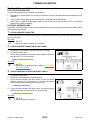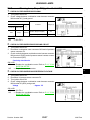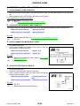
1
K ELECTRICAL
A
B
SECTION
DRIVER INFORMATION SYSTEM
C
D
E
CONTENTS
PRECAUTION ............................................................ 3
Precautions for Supplemental Restraint System
(SRS) “AIR BAG” and “SEAT BELT PRE-TENSIONER” .................................................................. 3
Wiring Diagrams and Trouble Diagnosis .................. 3
PREPARATION ........................................................... 4
Commercial Service Tool ......................................... 4
COMBINATION METERS ........................................... 5
System Description .................................................. 5
UNIFIED METER CONTROL UNIT ...................... 5
POWER SUPPLY AND GROUND CIRCUIT ........ 6
WATER TEMPERATURE GAUGE ........................ 6
ENGINE OIL PRESSURE GAUGE ....................... 6
A/T OIL TEMPERATURE GAUGE ........................ 6
VOLTAGE GAUGE ................................................ 6
TACHOMETER ..................................................... 6
FUEL GAUGE ....................................................... 6
SPEEDOMETER ................................................... 6
CAN Communication System Description ................ 7
Component Parts and Harness Connector Location..... 7
Combination Meter ................................................... 8
CHECK .................................................................. 8
Circuit Diagram ........................................................ 9
Wiring Diagram — METER — ................................ 10
Terminals and Reference Value for Combination
Meter ...................................................................... 12
Meter/Gauge Operation and Odo/Trip Meter ......... 13
SELF-DIAGNOSIS FUNCTION .......................... 13
HOW TO INITIATE COMBINATION METER
SELF- DIAGNOSIS MODE ................................. 13
COMBINATION METER SELF-DIAGNOSIS
MODE FUNCTIONS ........................................... 13
How to Proceed With Trouble Diagnosis ................ 17
Diagnosis Flow ....................................................... 17
Power Supply and Ground Circuit Inspection ........ 18
Symptom Chart ...................................................... 19
Vehicle Speed Signal Inspection ............................ 19
Water Temperature Signal Inspection .................... 19
Engine Speed Signal Inspection ............................ 19
Engine Oil Pressure Signal Inspection ................... 20
Revision: October 2005
Fuel Level Sensor Unit Inspection .......................... 22
FUEL LEVEL SENSOR UNIT ............................. 22
LOW-FUEL WARNING LAMP ............................. 22
Fuel Gauge Fluctuates, Indicates Wrong Value, or
Varies ...................................................................... 24
Fuel Gauge Does Not Move to Full-position ........... 24
Electrical Components Inspection .......................... 25
FUEL LEVEL SENSOR UNIT CHECK ................ 25
Removal and Installation of Combination Meter ..... 25
COMPASS AND THERMOMETER ........................... 26
System Description ................................................. 26
OUTSIDE TEMPERATURE DISPLAY ................. 26
DIRECTION DISPLAY ......................................... 26
Wiring Diagram — COMPAS — ............................. 27
Trouble Diagnoses ................................................. 28
PRELIMINARY CHECK FOR THERMOMETER... 28
INSPECTION/COMPASS AND THERMOMETER ..................................................................... 28
Calibration Procedure for Compass ....................... 29
CORRECTION FUNCTIONS OF COMPASS ...... 29
INITIAL CORRECTION PROCEDURE FOR
COMPASS ........................................................... 29
WARNING LAMPS .................................................... 30
Schematic ............................................................... 30
Wiring Diagram — WARN — .................................. 31
Oil Pressure Warning Lamp Stays Off (Ignition
Switch ON) ............................................................. 37
Oil Pressure Warning Lamp Does Not Turn Off (Oil
Pressure Is Normal) ................................................ 39
A/T INDICATOR ........................................................ 40
Wiring Diagram — AT/IND — ................................. 40
A/T Indicator Does Not Illuminate ........................... 41
WARNING CHIME ..................................................... 42
Component Parts and Harness Connector Location... 42
System Description ................................................. 42
FUNCTION .......................................................... 42
IGNITION KEY WARNING CHIME ..................... 43
LIGHT WARNING CHIME ................................... 43
SEAT BELT WARNING CHIME ........................... 43
CAN Communication System Description .............. 43
DI-1
2005 Titan
F
G
H
I
J
DI
L
M
Wiring Diagram — CHIME — ................................. 44
Terminals and Reference Value for BCM ................ 46
Terminals and Reference Value for Combination
Meter ...................................................................... 47
How to Proceed With Trouble Diagnosis ................ 47
Preliminary Check .................................................. 47
INSPECTION FOR POWER SUPPLY AND
GROUND CIRCUIT ............................................. 47
CONSULT-II Function (BCM) .................................. 49
CONSULT-II BASIC OPERATION PROCEDURE
... 49
DATA MONITOR .................................................. 50
ACTIVE TEST ..................................................... 50
SELF-DIAGNOSTIC RESULTS ........................... 51
All Warning Chimes Do Not Operate ...................... 51
Key Warning Chime and Light Warning Chime Do
Not Operate (Seat Belt Warning Chime Does Operate) ......................................................................... 52
Key Warning Chime Does Not Operate .................. 53
Light Warning Chime Does Not Operate ................ 55
Seat Belt Warning Chime Does Not Operate ......... 56
REAR SONAR SYSTEM ........................................... 58
Component Parts and Harness Connector Location... 58
System Description ................................................. 59
FUNCTION .......................................................... 59
REAR SONAR SYSTEM OFF SWITCH .............. 59
Revision: October 2005
DI-2
SONAR BUZZER .................................................59
REAR SONAR SENSOR .....................................60
Wiring Diagram — SONAR — ................................61
Terminals And Reference Value For Sonar Control
Unit ..........................................................................63
How to Proceed With Trouble Diagnosis ................63
Pre-diagnosis Inspection .........................................64
SENSOR STATUS CHECK .................................64
Self-diagnosis Function ...........................................64
ENTERING DIAGNOSTICS MODE .....................64
REQUESTING NUMBER OF FAULT CODES
MODE ..................................................................64
REQUESTING FAULT CODES MODE ................65
IDLING OR CLEARING FAULT CODES MODE...65
Preliminary Check ...................................................66
INSPECTION FOR POWER SUPPLY AND
GROUND CIRCUIT .............................................66
Symptom Chart .......................................................67
Component Inspection ............................................68
SONAR BUZZER .................................................68
REAR SONAR SYSTEM OFF SWITCH ..............68
REAR SONAR SYSTEM OFF INDICATOR .........69
Removal and Installation of Rear Sonar System ...69
REAR SONAR SENSORS ...................................69
SONAR CONTROL UNIT ....................................69
2005 Titan
PRECAUTION
PRECAUTION
PFP:00011
Precautions for Supplemental Restraint System (SRS) “AIR BAG” and “SEAT
BELT PRE-TENSIONER”
A
EKS00ACO
The Supplemental Restraint System such as “AIR BAG” and “SEAT BELT PRE-TENSIONER”, used along
with a front seat belt, helps to reduce the risk or severity of injury to the driver and front passenger for certain
types of collision. This system includes seat belt switch inputs and dual stage front air bag modules. The SRS
system uses the seat belt switches to determine the front air bag deployment, and may only deploy one front
air bag, depending on the severity of a collision and whether the front occupants are belted or unbelted.
Information necessary to service the system safely is included in the SRS and SB section of this Service Manual.
WARNING:
●
To avoid rendering the SRS inoperative, which could increase the risk of personal injury or death
in the event of a collision which would result in air bag inflation, all maintenance must be performed by an authorized NISSAN/INFINITI dealer.
●
Improper maintenance, including incorrect removal and installation of the SRS, can lead to personal injury caused by unintentional activation of the system. For removal of Spiral Cable and Air
Bag Module, see the SRS section.
●
Do not use electrical test equipment on any circuit related to the SRS unless instructed to in this
Service Manual. SRS wiring harnesses can be identified by yellow and/or orange harnesses or
harness connectors.
Wiring Diagrams and Trouble Diagnosis
B
C
D
E
F
G
EKS00ACP
When you read wiring diagrams, refer to the following:
●
Refer to GI-15, "How to Read Wiring Diagrams" .
●
Refer to PG-4, "POWER SUPPLY ROUTING CIRCUIT" for power distribution circuit.
When you perform trouble diagnosis, refer to the following:
●
Refer to GI-11, "HOW TO FOLLOW TEST GROUPS IN TROUBLE DIAGNOSES" .
●
Refer to GI-27, "How to Perform Efficient Diagnosis for an Electrical Incident" .
H
I
J
DI
L
M
Revision: October 2005
DI-3
2005 Titan
PREPARATION
PREPARATION
Commercial Service Tool
PFP:00002
EKS00ACQ
Tool name
Description
Power tool
Loosening bolts and nuts.
PBIC0191E
Revision: October 2005
DI-4
2005 Titan
COMBINATION METERS
COMBINATION METERS
System Description
PFP:24814
A
EKS00ACR
UNIFIED METER CONTROL UNIT
●
●
●
●
●
Speedometer, odometer, tachometer, fuel gauge, oil pressure gauge, voltage gauge, A/T oil temperature
gauge, and water temperature gauge are controlled by the unified meter control unit, which is built into the
combination meter.
Warning indicators are controlled by signals drawn from the CAN communication system, and components connected directly to the combination meter.
Digital meter is adopted for odometer/trip meters*, as well as the A/T position indicator display.
*The record of the odometer is kept even if the battery cable is disconnected.
Odometer/trip meters and A/T indicator segments can be checked in diagnosis mode.
Meters/gauges can be checked in diagnosis mode.
Illumination control
B
C
D
E
The unified meter control unit outputs the speedometer, odometer/trip meters, tachometer, engine oil pressure
gauge, voltage gauge, A/T indicator, A/T oil temperature gauge, fuel and temperature gauge lighting when the
ignition switch is turned on. When the headlamp (combination) switch is turned on, the illumination control
switch can be used to adjust the brightness of the combination meter illumination and the odometer/trip meters
and meter illumination. When the ignition switch is turned from the OFF to the ON position, the combination
meter dial lighting will remain off for 0.7 seconds. For additional combination meter illumination control information, refer to LT-152, "System Description" .
F
G
H
I
J
DI
L
M
Revision: October 2005
DI-5
2005 Titan
COMBINATION METERS
POWER SUPPLY AND GROUND CIRCUIT
Power is supplied at all times
●
through 10A fuse [No.19, located in the fuse block (J/B)]
●
to combination meter terminal 8.
With the ignition switch in the ON or START position, power is supplied
●
through 10A fuse [No.14, located in the fuse block (J/B)]
●
to combination meter terminal 24.
With the ignition switch in the ACC or ON position, power is supplied
●
through 10A fuse [No.4, located in the fuse block (J/B)]
●
to combination meter terminal 1.
Ground is supplied
●
to combination meter terminal 17
●
through body grounds M57, M61 and M79.
WATER TEMPERATURE GAUGE
The water temperature gauge indicates the engine coolant temperature.
ECM provides an engine coolant temperature signal to combination meter via CAN communication lines.
ENGINE OIL PRESSURE GAUGE
The engine oil pressure gauge indicates the engine oil pressure.
With the ignition switch in the ON or START position, power is supplied
●
through combination meter terminal 22
●
to oil pressure sensor terminal 1.
Ground is supplied
●
through combination meter terminal 16
●
to oil pressure sensor terminal 3.
The combination meter receives the oil pressure signal from oil pressure sensor
●
through oil pressure sensor terminal 2
●
to combination meter terminal 20.
NOTE:
This gauge is not designed to indicate low oil level. Use the oil level gauge to check the oil level.
A/T OIL TEMPERATURE GAUGE
The A/T oil temperature gauge indicates the A/T fluid temperature.
TCM provides a A/T oil temperature signal to combination meter via CAN communication lines.
VOLTAGE GAUGE
The voltage gauge indicates the battery/charging system voltage.
The voltage gauge is regulated by the unified meter control unit.
TACHOMETER
The tachometer indicates engine speed in revolutions per minute (rpm).
ECM provides an engine speed signal to combination meter via CAN communication lines.
FUEL GAUGE
The fuel gauge indicates the approximate fuel level in the fuel tank.
The fuel gauge is regulated by the unified meter control unit and a variable resistor signal supplied
●
to combination meter terminal 15
●
through fuel level sensor unit and fuel pump terminal 2
●
through fuel level sensor unit and fuel pump terminal 5
●
from combination meter terminal 16.
SPEEDOMETER
ABS actuator and electric unit (control unit) provides a vehicle speed signal to the combination meter via CAN
communication lines.
Revision: October 2005
DI-6
2005 Titan
COMBINATION METERS
CAN Communication System Description
EKS00ACS
A
Refer to LAN-7, "CAN COMMUNICATION" .
Component Parts and Harness Connector Location
EKS00ACT
B
C
D
E
F
G
H
I
WKIA4400E
1.
Fuse block (J/B)
2.
Combination meter M24
3.
Fuel level sensor unit and fuel pump
C5 (view with fuel tank removed)
4.
ECM E16
(view with battery removed)
5.
ABS actuator and electric unit (control unit) E125
6.
Oil pressure sensor F4
A. Oil pan (upper)
7.
A/T assembly F9
J
DI
L
M
Revision: October 2005
DI-7
2005 Titan
COMBINATION METERS
Combination Meter
EKS00ACU
CHECK
WKIA3855E
Revision: October 2005
DI-8
2005 Titan
COMBINATION METERS
Circuit Diagram
EKS00ACV
A
B
C
D
E
F
G
H
I
J
DI
L
M
WKWA4563E
Revision: October 2005
DI-9
2005 Titan
COMBINATION METERS
Wiring Diagram — METER —
EKS00ACW
WKWA4556E
Revision: October 2005
DI-10
2005 Titan
COMBINATION METERS
A
B
C
D
E
F
G
H
I
J
DI
L
M
WKWA4557E
Revision: October 2005
DI-11
2005 Titan
COMBINATION METERS
Terminals and Reference Value for Combination Meter
Terminal
No.
Wire
color
1
O
Condition
EKS00ACX
Ignition
switch
Operation or condition
Reference value (V)
(Approx.)
Ignition switch ACC or
ON
ACC
—
Battery voltage
Battery power supply
Item
8
Y/R
OFF
—
Battery voltage
11
L
CAN-H
—
—
—
12
P
CAN-L
—
—
—
15
Y/L
Fuel level sensor signal
—
—
Refer to DI-22, "Fuel Level Sensor
Unit Inspection" .
16
B/P
Fuel level sensor and oil
pressure sensor ground
ON
—
Refer to DI-22, "Fuel Level Sensor
Unit Inspection" .
17
B
Ground
—
—
18
BR
Illumination control switch
—
20
Y
Oil pressure sensor signal
ON
—
0 - 5V
22
GR/L
Oil pressure sensor
power supply
ON
—
5V
24
O/L
Ignition switch ON or
START
ON
—
Battery voltage
Revision: October 2005
Lighting switch ON
DI-12
0V
Refer to LT-153, "ILLUMINATION
OPERATION BY LIGHTING
SWITCH" .
2005 Titan
COMBINATION METERS
Meter/Gauge Operation and Odo/Trip Meter
EKS00ACY
A
SELF-DIAGNOSIS FUNCTION
The following items can be checked during Combination Meter Self-Diagnosis Mode.
●
Gauge sweep and present gauge values.
●
Illuminates all odometer, fuel, and engine temperature segments.
●
Illuminates all micro controlled lamps/LEDs regardless of switch configuration.
●
Displays estimated present battery voltage.
●
Displays seat belt buckle switch LH status.
B
C
HOW TO INITIATE COMBINATION METER SELF- DIAGNOSIS MODE
NOTE:
Once entered, Combination Meter Self-Diagnosis Mode will function with the ignition switch in ON or START.
Combination Meter Self-Diagnosis Mode will exit upon turning the ignition switch to OFF or ACC.
To initiate Combination Meter Self-Diagnosis Mode, refer to the following procedure.
1. Turn the ignition switch ON, while holding the odometer/trip meter switch for 5 - 8 seconds.
NOTE:
If the diagnosis function is activated the odometer/trip meter will display tESt.
D
E
F
COMBINATION METER SELF-DIAGNOSIS MODE FUNCTIONS
To interpret Combination Meter Self-Diagnosis Mode functions, refer to the following table.
G
Event
Odometer/trip meter A/B
switch held from 5 to 8
seconds (or until
released)
Odometer Display
Description of Test/Data
tESt
Notes:
Return to normal operation of all lamps/LEDs and
displays hex ROM rev. If
a ROM checksum fault
exists, display alternates
between "r XXXX" and
"FAIL".
I
Odometer/trip meter A/B
switch engaged and
released = next test
requested
rXXXX, FAIL
Next test requested
nrXXXX
Displays hex ROM rev as
stored in NVM.
GAGE
Performs sweep of all
gauges, then displays
present gauge values.
Performs checksum tests
on ROM and EE.
Gauges sweep within 10 seconds
Next test requested
(All segments illuminated)
Lights all odometer/trip
meter, fuel, and engine
temperature display segments.
Initiating self-diagnosis mode
complete
Next test requested
bulb
Illuminates all micro-controlled lamps/LEDs
regardless of SW configuration.
Next test requested
EE XX, FAIL
Hex EE level. If EE
checksum fault exists,
display alternates
between "EE XX" and
"FAIL".
Next test requested
dtXXXX
Hex coding of final manufacturing test date.
Next test requested
Revision: October 2005
H
Initiating self-diagnosis mode
DI-13
J
DI
L
M
2005 Titan
COMBINATION METERS
Event
Odometer Display
Description of Test/Data
Notes:
Next test requested
Sc1XX
Displays 8-bit software
configuration value in Hex
format.
Bit Coding
7-3 = reserved for future use
2 = TCS/VDC 0 = not present
1 = present
1 = Shift type 0 = Column shift
1 = Floor shift
0 = ICC
0 = not present
1 = present
Next test requested
Sc2XX
Displays 8-bit software
configuration value in Hex
format.
Bit coding
7-0 = Reserved for future use
Next test requested
EprXX
Displays 8-bit software
configuration value in Hex
format.
Bit Coding
7-2 = reserved for future use
1 = A/T Oil Temp (gauge)
0 = not present
1 = present
1 = Odo Units 0 = kilometers
1 = miles
Next test requested
1nFXX
Displays 8-bit market info
value in Hex format.
$31 = USA
$2A = Canada
$0E = GCC
Next test requested
cYLXX
Displays 8-bit engine configuration value in Hex
format.
$08 = 8 cylinder
$06 = 6 cylinder
Next test requested
FFXXXX
Displays 16-bit fuel flow
constant "Q" in tenths of
cc/min in Hex format.
$0000 - $FFFF
Next test requested
tF
Displays 16-bit tire factor
"A" in hundredths in Hex
format.
$0000 - $FFFF
Next test requested
ot1XX
Displays oil pressure telltale "on" threshold in A/D
counts in Hex format.
$00 - $FF
Next test requested
ot0XX
Displays oil pressure telltale "off" threshold in A/D
counts in Hex format.
$00 - $FF
XXXXX
Raw uncompensated
english speed value in
hundredths of MPH.
Speedometer indicates
present speed.
Will display "-----" if message is
not received. Will display
"99999" if data received is
invalid
Next test requested
XXXXX
Raw uncompensated
metric speed value in
hundredths of KPH.
Speedometer indicates
present speed.
Will display "-----" if message is
not received. Will display
"99999" if data received is
invalid
Next test requested
tXXXX
Tachometer value in
RPM. Tachometer indicates present RPM.
Will display "-----" if message is
not received.
F1 XXXX
Present ratioed fuel level
A/D input 1 in decimal format. Fuel gauge indicates
present filtered level.
000-009 = Short circuit
010-254 = Normal range
255 = Open circuit
--- = Missing 5 seconds
XXXC
Last temperature gauge
input value in degrees C.
Temperature gauge indicates present filtered temperature.
Will display "---"C if message is
not received.
Will display "999" if data
received is invalid.
Next test requested
Next test requested
Next test requested
Revision: October 2005
DI-14
2005 Titan
COMBINATION METERS
Event
Odometer Display
Description of Test/Data
Notes:
A
Next test requested
BAtXX.X
Estimated present battery voltage.
Next test requested
rES -X
Seat belt buckle switch
LH status.
Next test requested
PA -XX
Hex value port A.
Next test requested
Pb -XX
Hex value port B.
Next test requested
PE -XX
Hex value port E.
Next test requested
PL -XX
Hex value port L.
Next test requested
P6 -XX
Hex value port K.
Next test requested
Pn -XX
Hex value port M.
Next test requested
PP -XX
Hex value port P.
Next test requested
PS -XX
Hex value port S.
Next test requested
Pt -XX
Hex value port T.
Next test requested
Pu -XX
Hex value port U.
Next test requested
P4 -XX
Hex value port V.
Next test requested
Puu -XX
Hex value port W.
Next test requested
A01XXX
A/D port A/D value (nonratioed).
0-255
Next test requested
A02XXX
A/D port A/D value (nonratioed).
0-255
Next test requested
A03XXX
A/D port A/D value (nonratioed).
0-255
Next test requested
A04XXX
A/D port A/D value (nonratioed).
0-255
Next test requested
A05XXX
A/D port A/D value (nonratioed).
0-255
Next test requested
A06XXX
A/D port A/D value (nonratioed).
0-255
Next test requested
A07XXX
A/D port A/D value (nonratioed).
0-255
Next test requested
A08XXX
A/D port A/D value (nonratioed).
0-255
Next test requested
A09XXX
A/D port A/D value (nonratioed).
0-255
Next test requested
A10XXX
A/D port A/D value (nonratioed).
0-255
Next test requested
A11XXX
A/D port A/D value (nonratioed).
0-255
Next test requested
A12XXX
A/D port A/D value (nonratioed).
0-255
Next test requested
A13XXX
A/D port A/D value (nonratioed).
0-255
Next test requested
A14XXX
A/D port A/D value (nonratioed).
0-255
Next test requested
A15XXX
A/D port A/D value (nonratioed).
0-255
Next test requested
PA0-XX
Hex value representing
state of A/D ports 0-7.
Next test requested
PA1-XX
Hex value representing
state of A/D ports 0-7.
Revision: October 2005
DI-15
1= Buckled
0 = Unbuckled
B
C
D
E
F
G
H
I
J
DI
L
M
2005 Titan
COMBINATION METERS
Event
Odometer Display
Description of Test/Data
Notes:
Next test requested
Thr-XXX
Decimal value of thermistor A/D reading.
0-255
Next test requested
D-HI
Meter/LCD Illumination.
Full daytime brightness all
LCD segments active
Next test requested
N-HI
Meter/LCD Illumination.
Full nighttime brightness all
LCD segments active
Next test requested
N-LO
Meter/LCD Illumination.
Min. nighttime brightness all
LCD segments active
Next test requested
GAGE
Revision: October 2005
Return to beginning of selfdiagnosis.
DI-16
2005 Titan
COMBINATION METERS
How to Proceed With Trouble Diagnosis
1.
2.
3.
4.
5.
EKS00ACZ
A
Confirm the symptom or customer complaint.
Perform diagnosis according to diagnosis flow. Refer to DI-17, "Diagnosis Flow" .
According to the symptom chart, repair or replace the cause of the symptom.
Does the meter operate normally? If so, go to 5. If not, go to 2.
Inspection End.
Diagnosis Flow
B
EKS00AD0
C
1. CHECK WARNING INDICATOR ILLUMINATION
1.
2.
Turn ignition switch ON.
Make sure warning indicators (such as malfunction indicator lamp and oil pressure low/coolant temperature high warning indicator) illuminate.
Do warning indicators illuminate?
YES >> GO TO 2.
NO
>> Check ignition power supply system of combination meter. Refer to DI-18, "Power Supply and
Ground Circuit Inspection" .
D
E
F
2. CHECK SELF-DIAGNOSIS OPERATION OF COMBINATION METER
Perform combination meter self-diagnosis. Refer to DI-13, "SELF-DIAGNOSIS FUNCTION" .
Does self-diagnosis function operate?
YES >> GO TO 3.
NO
>> Check combination meter power supply and ground circuit. Refer to DI-18, "Power Supply and
Ground Circuit Inspection" .
3. CHECK ODOMETER OPERATION
G
H
I
Check segment display status of odometer.
Is the display normal?
YES >> GO TO 4.
NO
>> Replace the combination meter. Refer to IP-13, "COMBINATION METER" .
J
DI
L
WKIA1531E
4. CHECK COMBINATION METER CIRCUIT
M
Check indication of each meter/gauge in self-diagnosis mode.
OK or NG
OK
>> Go to DI-19, "Symptom Chart" .
NG
>> Replace the combination meter. Refer to IP-13, "COMBINATION METER" .
WKIA1532E
Revision: October 2005
DI-17
2005 Titan
COMBINATION METERS
Power Supply and Ground Circuit Inspection
EKS00AD1
1. CHECK FUSES
Check for blown combination meter fuses.
Unit
Power source
Combination meter
Fuse No.
Battery
19
Ignition switch ON or START
14
Ignition switch ACC or ON
4
Refer to DI-10, "Wiring Diagram — METER —" .
OK or NG
OK
>> GO TO 2.
NG
>> If fuse is blown, be sure to eliminate cause of malfunction before installing new fuse. Refer to PG4, "POWER SUPPLY ROUTING CIRCUIT" .
2. CHECK POWER SUPPLY CIRCUIT
1.
2.
Disconnect combination meter connector.
Check voltage between combination meter harness connector
terminals and ground.
Terminals
Ignition switch position
(+)
Connector
Terminal
(Wire color)
(–)
1 (O)
M24
8 (Y/R)
Ground
24 (O/L)
OFF
ACC
ON
0V
Battery
voltage
Battery
voltage
Battery
voltage
Battery
voltage
Battery
voltage
0V
0V
Battery
voltage
WKIA1815E
OK or NG
OK
>> GO TO 3.
NG
>> Check the harness for open between combination meter and fuse.
3. CHECK GROUND CIRCUIT
1.
2.
Turn ignition switch OFF.
Check continuity between combination meter harness connector
terminal and ground.
Terminals
(+)
(–)
Connector
Terminal
(Wire color)
M24
17 (B)
Ground
Continuity
Yes
WKIA1526E
OK or NG
OK
>> Inspection End.
NG
>> Repair harness or connector.
Revision: October 2005
DI-18
2005 Titan
COMBINATION METERS
Symptom Chart
EKS00AD2
A
Trouble phenomenon
Possible cause
Improper tachometer indication.
Refer to DI-19, "Engine Speed Signal Inspection" .
Improper water temperature gauge indication.
Refer to DI-19, "Water Temperature Signal Inspection" .
Improper speedometer or odometer.
Refer to DI-19, "Vehicle Speed Signal Inspection" .
Improper engine oil pressure gauge indication.
Refer to DI-20, "Engine Oil Pressure Signal Inspection" .
Improper A/T oil temperature gauge indication.
Refer to AT-128, "DTC P1710 A/T FLUID TEMPERATURE SENSOR CIRCUIT" .
Improper voltage meter indication.
Refer to IP-13, "COMBINATION METER" .
B
C
D
Improper fuel gauge indication.
Fuel warning lamp indication is irregular.
Refer to DI-22, "Fuel Level Sensor Unit Inspection" .
More than one gauge does not give proper indication.
Replace the combination meter. Refer to IP-13, "COMBINATION
METER" .
Improper A/T position indication.
Refer to DI-40, "A/T INDICATOR" .
Illumination control does not operate properly.
Refer to LT-152, "ILLUMINATION" .
E
F
Vehicle Speed Signal Inspection
EKS00AD3
1. CHECK ABS ACTUATOR AND ELECTRIC UNIT (CONTROL UNIT) SELF-DIAGNOSIS
G
Perform ABS actuator and electric unit (control unit) self-diagnosis. Refer to BRC-24, "SELF-DIAGNOSIS" .
Self-diagnostic result content
No malfunction detected>>Replace the combination meter. Refer to IP-13, "COMBINATION METER" .
Malfunction detected>>Perform the "Diagnostic Procedure" for displayed DTC.
H
Water Temperature Signal Inspection
I
EKS00AD4
1. CHECK ECM SELF-DIAGNOSIS
1. Perform ECM self-diagnosis. Refer to EC-131, "SELF-DIAG RESULTS MODE" .
Self-diagnostic result content
No malfunction detected>>Replace the combination meter. Refer to IP-13, "COMBINATION METER" .
Malfunction detected>>Perform "Diagnostic procedure" for displayed DTC.
Engine Speed Signal Inspection
J
DI
EKS00AD5
1. CHECK ECM SELF-DIAGNOSIS
L
1. Perform ECM self-diagnosis. Refer to EC-131, "SELF-DIAG RESULTS MODE" .
Self-diagnostic result content
No malfunction detected>>Replace the combination meter. Refer to IP-13, "COMBINATION METER" .
Malfunction detected>>Perform "Diagnostic procedure" for displayed DTC.
M
Revision: October 2005
DI-19
2005 Titan
COMBINATION METERS
Engine Oil Pressure Signal Inspection
EKS00AD6
1. CHECK OIL PRESSURE SENSOR SIGNAL
1.
2.
Turn ignition switch ON.
Check voltage between combination meter harness connector
M24 terminal 20 (Y) and ground.
Terminals
(+)
Connector
Terminal
(Wire color)
(–)
M24
20 (Y)
Ground
Condition
Voltage (V)
When ignition switch is in ON
position. (Engine stopped.)
Yes
Engine running. (Idle speed)
Yes
WKIA1833E
OK or NG
OK
>> Replace combination meter. Refer to IP-13, "COMBINATION METER" .
NG
>> GO TO 2.
2. CHECK OIL PRESSURE SENSOR SIGNAL
1.
2.
3.
4.
Turn ignition switch OFF.
Disconnect oil pressure sensor connector F4.
Turn ignition switch ON.
Check voltage between combination meter harness connector
M24 terminal 22 (GR/L) and ground.
Voltage
: Approx. 5V
OK or NG
OK
>> GO TO 3.
NG
>> Replace combination meter. Refer to IP-13, "COMBINATION METER" .
WKIA1834E
3. CHECK OIL PRESSURE SENSOR POWER SUPPLY CIRCUIT
1.
2.
3.
Turn ignition switch OFF.
Disconnect combination connector M24.
Check continuity between combination meter harness connector M24 terminal 22 (GR/L) and oil pressure
sensor harness connector F4 terminal 1 (GR/L).
Continuity should exist.
4.
Check continuity between combination meter harness connector
M24 terminal 22 (GR/L) and ground.
Continuity should not exist.
OK or NG
OK
>> GO TO 4.
NG
>> Repair harness or connector.
WKIA1835E
Revision: October 2005
DI-20
2005 Titan
COMBINATION METERS
4. CHECK OIL PRESSURE SENSOR SIGNAL CIRCUIT
1.
A
Check continuity between combination meter harness connector M24 terminal 20 (Y) and oil pressure
sensor harness connector F4 terminal 2 (Y).
B
Continuity should exist.
2.
Check continuity between combination meter harness connector
M24 terminal 20 (Y) and ground.
C
Continuity should not exist.
OK or NG
OK
>> GO TO 5.
NG
>> Repair harness or connector.
D
E
WKIA1836E
5. CHECK OIL PRESSURE SENSOR GROUND CIRCUIT
F
Check continuity between combination meter harness connector
M24 terminal 16 (B/P) and oil pressure sensor harness connector F4
terminal 3 (B/P).
G
Continuity should exist.
H
OK or NG
OK
>> Replace oil pressure sensor.
NG
>> Repair harness or connector.
I
WKIA1837E
J
DI
L
M
Revision: October 2005
DI-21
2005 Titan
COMBINATION METERS
Fuel Level Sensor Unit Inspection
EKS00AD7
FUEL LEVEL SENSOR UNIT
The following symptoms do not indicate a malfunction.
●
Depending on vehicle position or driving circumstance, the fuel in the tank shifts and the indication may
fluctuate.
●
If the vehicle is fueled with the ignition switch ON, the indication will update slowly.
●
If the vehicle is tilted when the ignition switch is turned ON, fuel in the tank may flow to one direction
resulting in a change of reading.
LOW-FUEL WARNING LAMP
Depending on vehicle posture or driving circumstances, the fuel level in the tank varies, and the warning lamp
ON timing may be changed.
1. CHECK HARNESS CONNECTOR
Check combination meter and fuel level sensor unit and fuel pump terminals (meter-side, and harness-side)
for poor connection.
OK or NG
OK
>> GO TO 2.
NG
>> Repair or replace terminals or connectors.
2. CHECK HARNESS CONNECTOR OUTPUT SIGNAL
1.
2.
3.
Disconnect fuel level sensor unit and fuel pump connector.
Turn ignition switch ON.
Check voltage between combination meter harness connector
M24 terminal 15 (Y/L) and ground.
Battery voltage should exist.
OK or NG
OK
>> GO TO 3.
NG
>> Replace the combination meter. Refer to IP-13, "COMBINATION METER" .
WKIA1816E
3. CHECK HARNESS FOR OPEN OR SHORT CIRCUIT
1.
2.
3.
Turn ignition switch OFF.
Disconnect combination meter connector M24.
Check continuity between fuel level sensor unit and fuel pump
harness connector C5 (A) terminal 2 (Y/L) and combination
meter harness connector M24 (B) terminal 15 (Y/L).
Continuity should exist.
4.
Check continuity between fuel level sensor unit and fuel pump
harness connector C5 (A) terminal 2 (Y/L) and ground.
Continuity should not exist.
OK or NG
OK
>> GO TO 4.
NG
>> Repair harness or connector.
Revision: October 2005
WKIA4617E
DI-22
2005 Titan
COMBINATION METERS
4. CHECK FUEL LEVEL SENSOR CIRCUIT
1.
A
Check continuity between combination meter harness connector
M24 terminal 16 (B/P) and fuel level sensor unit and fuel pump
harness connector C5 terminal 5 (B/P).
B
Continuity should exist.
2.
Check continuity between fuel level sensor unit and fuel pump
harness connector C5 terminal 5 (B/P) and ground.
C
Continuity should not exist.
D
OK or NG
OK
>> GO TO 5.
NG
>> Repair harness or connector.
WKIA2071E
E
5. CHECK FUEL LEVEL SENSOR UNIT
Check the fuel level sensor unit. Refer to DI-25, "FUEL LEVEL SENSOR UNIT CHECK" .
OK or NG
OK
>> GO TO 6.
NG
>> Replace the fuel level sensor unit. Refer to FL-5, "Removal and Installation" .
F
G
6. CHECK INSTALLATION CONDITION
Check fuel level sensor unit installation, and determine whether the float arm interferes or binds with any of the
internal components in the fuel tank.
OK or NG
OK
>> Replace the combination meter. Refer to IP-13, "COMBINATION METER" .
NG
>> Install the fuel level sensor unit properly.
H
I
J
DI
L
M
Revision: October 2005
DI-23
2005 Titan
COMBINATION METERS
Fuel Gauge Fluctuates, Indicates Wrong Value, or Varies
EKS00AD8
1. CHECK FUEL GAUGE FLUCTUATION
Test drive vehicle to see if gauge fluctuates only during driving or just before or just after stopping.
Does the indication value vary only during driving or just before or just after stopping?
YES >> The fluctuation may be caused by fuel level change in the fuel tank. Condition is normal.
NO
>> Ask the customer about the situation when the symptom occurs in detail, Refer to DI-22, "Fuel
Level Sensor Unit Inspection" .
Fuel Gauge Does Not Move to Full-position
EKS00AD9
1. CHECK POINTER MOVEMENT TO FULL-POSITION
Does it take a long time for the pointer to move to full-position?
YES or NO
YES >> GO TO 2.
NO
>> GO TO 3.
2. CHECK IGNITION SWITCH POSITION
Was the vehicle fueled with the ignition switch ON?
YES or NO
YES >> Be sure to fuel the vehicle with the ignition switch OFF. Otherwise, it will take a long time for the
pointer to move to full-position because of the characteristic of the fuel gauge.
NO
>> GO TO 3.
3. OBSERVE VEHICLE POSITION
Is the vehicle parked on an incline?
YES or NO
YES >> Check the fuel level indication with vehicle on a level surface.
NO
>> GO TO 4.
4. CHECK POINTER MOVEMENT TO EMPTY-POSITION
During driving, does the fuel gauge move gradually toward empty-position?
YES or NO
YES >> Check the fuel level sensor unit. Refer to DI-25, "FUEL LEVEL SENSOR UNIT CHECK" .
NO
>> Check fuel level sensor unit installation, and determine whether the float arm interferes or binds
with any of the internal components in the fuel tank.
Revision: October 2005
DI-24
2005 Titan
COMBINATION METERS
Electrical Components Inspection
EKS00ADA
A
FUEL LEVEL SENSOR UNIT CHECK
For removal, refer to FL-5, "Removal and Installation" .
Check Fuel Level Sensor Unit and Fuel Pump
B
Check resistance between fuel level sensor unit and fuel pump connector terminals 2 and 5.
Terminals
2
5
Float position
mm (in)
Resistance
value Ω
(Approx.)
C
D
*1
Empty
25.86 (1.02)
81.66
*2
Full
254.6 (10.02)
6.98
*1 and *2: When float rod is in contact with stopper.
E
LKIA0402E
Removal and Installation of Combination Meter
EKS00ADB
F
Refer to IP-13, "COMBINATION METER" .
G
H
I
J
DI
L
M
Revision: October 2005
DI-25
2005 Titan
COMPASS AND THERMOMETER
COMPASS AND THERMOMETER
System Description
PFP:24835
EKS00D78
This unit displays the following items:
●
Earth magnetism and heading direction of vehicle.
●
Outside air temperature.
●
Caution for frozen road surfaces.
WKIA1817E
OUTSIDE TEMPERATURE DISPLAY
Push the mode switch when the ignition switch is in the ON position. The outside temperature will be displayed
in “°F”.
●
Selecting the indication range
Push the mode switch to change from °F → °C → OFF → °F.
●
The indicated temperature on the thermometer is not readily affected by engine heat. It changes only
when one of the following conditions is present.
–
The temperature detected by the ambient sensor is lower than the indicated temperature on the thermometer.
–
The vehicle speed is greater than 20 km/h (13 MPH).
(This is to prevent the indicated temperature from being affected by engine heat during low-speed driving.)
–
The ignition switch has been turned to the OFF position for more than 2 hours. (The engine is cold.)
DIRECTION DISPLAY
Push the mode switch when the ignition switch is in the ON position. The direction will be displayed.
Revision: October 2005
DI-26
2005 Titan
COMPASS AND THERMOMETER
Wiring Diagram — COMPAS —
EKS00D79
A
B
C
D
E
F
G
H
I
J
DI
L
M
WKWA4558E
Revision: October 2005
DI-27
2005 Titan
COMPASS AND THERMOMETER
Trouble Diagnoses
EKS00D7A
PRELIMINARY CHECK FOR THERMOMETER
1. COOL DOWN CHECK
1. Turn the ignition switch to the ON position.
2. Cool down the ambient sensor 2 with water or ice.
Does the indicated temperature drop?
YES >> GO TO 2.
NO
>> The system is malfunctioning. Refer to DI-28, "INSPECTION/COMPASS AND THERMOMETER"
.
2. WARM UP CHECK
1. Leave the vehicle for 10 minutes.
2. With the ignition switch in the ON position, disconnect and reconnect the ambient sensor 2 connector.
Does the indicated temperature rise?
YES >> The system is OK.
NO
>> The system is malfunctioning. Refer to DI-28, "INSPECTION/COMPASS AND THERMOMETER"
.
NOTE:
The indicated temperature on the thermometer is not readily affected by engine heat. It changes only when
one of the following conditions is present.
●
The temperature detected by the ambient sensor is lower than the indicated temperature on the thermometer.
●
The vehicle speed is greater than 20 km/h (13 MPH).
(This is to prevent the indicated temperature from being affected by engine heat during low-speed driving.)
●
The ignition switch has been turned to the OFF position for more than 2 hours. (The engine is cold.)
INSPECTION/COMPASS AND THERMOMETER
Symptom
No display at all
Possible causes
Repair order
1. 10A fuse
1. Check 10A fuse [No. 12, located in fuse block (J/B)].
Turn the ignition switch ON and verify that battery positive voltage is at terminal 2 of compass and thermometer.
2. Ground circuit
3. Compass and thermometer
2. Check ground circuit for compass and thermometer.
3. Replace compass and thermometer.
Forward direction indication slips off the mark
or incorrect
1. In manual correction mode (Bar and
display vanish)
1. Drive the vehicle and turn at an angle of 90°.
Compass reading
remains unchanged
1. Vehicle speed signal is not entered
Displays wrong temperature when ambient
temperature is between
−40°C (−40°F) and
55°C (130°F) (See
NOTE above)
1. Check operation
1. Perform preliminary check shown above.
2. Ambient sensor circuit
2. Check harness for open or short between ambient sensor 2 and
compass and thermometer.
2. Perform the zone variation change.
2. Zone variation change is not done
2. Compass and thermometer
1. Check harness for open or short between combination meter
terminal 29 and compass and thermometer terminal 8.
2. Replace compass and thermometer.
3. Vehicle speed signal is not entered
4. Ambient sensor 2
5. Compass and thermometer
3. Check harness for open or short between combination meter
terminal 29 and compass and thermometer terminal 8.
4. Replace ambient sensor 2.
5. Replace compass and thermometer.
Displays SC or OC
1. Ambient sensor circuit
2. Ambient sensor 2
1. Check harness for open or short between ambient sensor 2 and
compass and thermometer.
3. Compass and thermometer
2. Replace ambient sensor 2.
3. Replace compass and thermometer.
Revision: October 2005
DI-28
2005 Titan
COMPASS AND THERMOMETER
Calibration Procedure for Compass
EKS00D7B
The difference between magnetic North and geographical North can sometimes be great enough to cause
false compass readings. In order for the compass to operate accurately in a particular zone, it must be calibrated using the following procedure.
A
B
C
D
E
F
G
H
I
WKIA3604E
J
CORRECTION FUNCTIONS OF COMPASS
The direction display is equipped with automatic correction function.
If the direction is not shown correctly, carry out initial correction.
DI
L
M
WKIA1817E
INITIAL CORRECTION PROCEDURE FOR COMPASS
1.
Pushing the mode switch for about 10 seconds will enter the initial correction mode. The compass display
will begin to flash.
2. Turn the vehicle slowly in an open, safe place. The initial correction is completed in approximately one
and a half turns.
NOTE:
In places where the terrestrial magnetism is extremely disturbed, the initial correction may start automatically.
Revision: October 2005
DI-29
2005 Titan
WARNING LAMPS
WARNING LAMPS
Schematic
PFP:24814
EKS00ADG
WKWA4559E
Revision: October 2005
DI-30
2005 Titan
WARNING LAMPS
Wiring Diagram — WARN —
EKS00ADH
A
B
C
D
E
F
G
H
I
J
DI
L
M
WKWA4564E
Revision: October 2005
DI-31
2005 Titan
WARNING LAMPS
WKWA4560E
Revision: October 2005
DI-32
2005 Titan
WARNING LAMPS
A
B
C
D
E
F
G
H
I
J
DI
L
M
WKWA4561E
Revision: October 2005
DI-33
2005 Titan
WARNING LAMPS
WKWA2369E
Revision: October 2005
DI-34
2005 Titan
WARNING LAMPS
A
B
C
D
E
F
G
H
I
J
DI
L
M
WKWA2388E
Revision: October 2005
DI-35
2005 Titan
WARNING LAMPS
4WD Models
WKWA4565E
Revision: October 2005
DI-36
2005 Titan
WARNING LAMPS
Oil Pressure Warning Lamp Stays Off (Ignition Switch ON)
EKS00D7C
1. CHECK OIL PRESSURE SENSOR SIGNAL
1.
2.
A
Turn ignition switch ON.
Check voltage between combination meter harness connector
M24 terminal 20 (Y) and ground.
B
Terminals
C
(+)
Connector
M24
Condition
Terminal
(Wire color)
20 (Y)
Voltage (V)
(–)
D
Ground
When ignition switch is in ON
position. (Engine stopped)
Yes
Engine running. (Idle speed)
Yes
WKIA1833E
OK or NG
OK
>> GO TO 2.
NG
>> GO TO 3.
E
F
2. CHECK OIL PRESSURE SENSOR GROUND CIRCUIT
1.
2.
3.
G
Turn ignition switch OFF.
Disconnect combination meter connector M24 and oil pressure
sensor connector F4.
Check continuity between combination meter harness connector
M24 terminal 16 (B/P) and oil pressure sensor harness connector F4 terminal 3 (B/P).
H
I
Continuity should exist.
OK or NG
OK
>> Replace the combination meter. Refer to IP-13, "COMBINATION METER" .
NG
>> Repair harness or connector.
J
WKIA1837E
DI
3. CHECK OIL PRESSURE SENSOR REFERENCE VOLTAGE
1.
2.
3.
4.
Turn ignition switch OFF.
Disconnect oil pressure sensor connector F4.
Turn ignition switch ON.
Check voltage between combination meter harness connector
M24 terminal 22 (GR/L) and ground.
Voltage
L
M
: Approx. 5V
OK or NG
OK
>> GO TO 4.
NG
>> Replace the combination meter. Refer to IP-13, "COMBINATION METER" .
WKIA1834E
Revision: October 2005
DI-37
2005 Titan
WARNING LAMPS
4. CHECK OIL PRESSURE SENSOR POWER SUPPLY CIRCUIT
1.
2.
3.
Turn ignition switch OFF.
Disconnect combination meter connector M24.
Check continuity between combination meter harness connector M24 terminal 22 (GR/L) and oil pressure
sensor harness connector F4 terminal 1 (GR/L).
Continuity should exist.
4.
Check continuity between combination meter harness connector
M24 terminal 22 (GR/L) and ground.
Continuity should not exist.
OK or NG
OK
>> GO TO 5.
NG
>> Repair harness or connector.
WKIA1835E
5. CHECK OIL PRESSURE SENSOR SIGNAL CIRCUIT
1.
Check continuity between combination meter harness connector M24 terminal 20 (Y) and oil pressure
sensor harness connector F4 terminal 2 (Y).
Continuity should exist.
2.
Check continuity between combination meter harness connector
M24 terminal 20 (Y) and ground.
Continuity should not exist.
OK or NG
OK
>> GO TO 6.
NG
>> Repair harness or connector.
WKIA1836E
6. CHECK OIL PRESSURE SENSOR GROUND CIRCUIT
Check continuity between combination meter harness connector
M24 terminal 16 (B/P) and ground.
Continuity should not exist.
OK or NG
OK
>> Replace oil pressure sensor.
NG
>> Repair harness or connector.
WKIA2685E
Revision: October 2005
DI-38
2005 Titan
WARNING LAMPS
Oil Pressure Warning Lamp Does Not Turn Off (Oil Pressure Is Normal)
EKS00D7D
A
NOTE:
For oil pressure inspection, refer to LU-7, "OIL PRESSURE CHECK" .
1. CHECK ENGINE OIL PRESSURE GAUGE OPERATION
B
Observe operation of engine oil pressure gauge.
Does engine oil pressure gauge function properly?
YES >> Replace the combination meter. Refer to IP-13, "COMBINATION METER" .
NO
>> Go to DI-20, "Engine Oil Pressure Signal Inspection" .
C
D
E
F
G
H
I
J
DI
L
M
Revision: October 2005
DI-39
2005 Titan
A/T INDICATOR
A/T INDICATOR
Wiring Diagram — AT/IND —
PFP:24814
EKS00ADI
WKWA2390E
Revision: October 2005
DI-40
2005 Titan
A/T INDICATOR
A/T Indicator Does Not Illuminate
EKS00ADJ
1. CHECK SELF-DIAGNOSIS OF COMBINATION METER
A
Perform combination meter self-diagnosis. Refer to DI-13, "SELF-DIAGNOSIS FUNCTION" .
OK or NG
OK
>> GO TO 2.
NG
>> Replace combination meter. Refer to IP-13, "COMBINATION METER" .
B
C
2. CHECK TCM
Perform self-diagnosis of TCM. Refer to AT-88, "SELF-DIAGNOSTIC RESULT MODE" .
OK or NG
OK
>> Replace combination meter. Refer to IP-13, "COMBINATION METER" .
NG
>> Refer to DI-13, "SELF-DIAGNOSIS FUNCTION" .
D
E
F
G
H
I
J
DI
L
M
Revision: October 2005
DI-41
2005 Titan
WARNING CHIME
WARNING CHIME
Component Parts and Harness Connector Location
PFP:24814
EKS00ADK
LKIA0688E
1.
Combination meter M24
2.
Combination switch (lighting switch) 3.
M28
Steering column
4.
BCM M18, M20 (view with instrument lower panel LH removed)
5.
Front door switch LH B8
Key switch and key lock solenoid
M27 (floor shift)
Key switch M80 (column shift)
7.
Seat belt buckle switch LH B12
System Description
6.
EKS00ADL
FUNCTION
Power is supplied at all times
●
through 50A fusible link (letter f , located in the fuse and fusible link box)
●
to BCM terminal 70, and
●
through 10A fuse [No. 19, located in the fuse block (J/B)]
●
to key switch and key lock solenoid terminal 3 (floor shift) or key switch terminal 3 (console shift).
With ignition switch in ON or START position, power is supplied
●
through 10A fuse (No. 59, located in the fuse and relay box)
●
to BCM terminal 38.
Ground is supplied
●
to BCM terminal 67
●
through body grounds M57, M61, and M79.
NOTE:
When ignition key warning chime, light warning chime, and seat belt warning chime are required at the same
time, the priorities for each chime are the following.
1. Light warning chime
2. Ignition key warning chime
Revision: October 2005
DI-42
2005 Titan
WARNING CHIME
3.
Seat belt warning chime
A
IGNITION KEY WARNING CHIME
With the key inserted in the ignition switch, the ignition switch in OFF position, and the driver's door open, the
warning chime will sound.
Power is supplied
●
through key switch and key lock solenoid terminal 4 (floor shift) or key switch terminal 4 (column shift)
●
to BCM terminal 37.
Ground is supplied
●
to BCM terminal 47
●
through front door switch LH terminal 2
●
through body grounds B7 and B19 (king cab) or through front door switch LH case ground (crew cab).
BCM detects key inserted into the ignition switch, and sends key warning signal to combination meter via CAN
communication lines. When the combination meter receives key warning signal, it sounds warning chime.
B
C
D
E
LIGHT WARNING CHIME
With the key removed from the ignition switch, the driver's door open, and the lighting switch (part of the combination switch) in 1st or 2nd position, the warning chime will sound. [Except when headlamp battery saver
control operates (5 minutes after ignition switch is turned to OFF or ACC position) and headlamps do not illuminate.]
Signal is supplied
●
from combination switch (lighting switch) terminals 1, 2, 3, 4, 5, 6, 7, 8, 9 and 10
●
to BCM terminals 2, 3, 4, 5, 6, 32, 33, 34, 35 and 36.
NOTE:
BCM detected lighting switch in 1st or 2nd position. Refer to BCS-3, "COMBINATION SWITCH READING
FUNCTION" .
Ground is supplied
●
to BCM terminal 47
●
through front door switch LH terminal 2.
●
through body grounds B7 and B19 (king cab) or through front door switch LH case ground (crew cab).
BCM detects headlamps are illuminated, and sends light warning signal to combination meter CAN communication lines. When the combination meter receives light warning signal, it sounds warning chime.
G
H
I
J
DI
SEAT BELT WARNING CHIME
When the ignition switch is turned ON with the seat belt unfastened (seat belt buckle switch LH unfastened),
warning chime will sound for approximately 6 seconds.
Ground is supplied
●
to combination meter terminal 27
●
through seat belt buckle switch LH terminal 1.
Seat belt buckle switch LH terminal 2 is grounded through body grounds B7 and B19.
The combination meter sends seat belt buckle switch LH unfastened signal to BCM via CAN communication
line.
BCM receives seat belt buckle switch LH unfastened signal from combination meter via CAN communication
line, and sends seat belt warning signal to the combination meter via CAN communication line. When the
combination meter receives the seat belt warning signal, it sounds the warning chime. The BCM controls the
(6 second) duration of the seat belt warning chime.
CAN Communication System Description
EKS00ADM
Refer to LAN-7, "CAN COMMUNICATION" .
Revision: October 2005
F
DI-43
2005 Titan
L
M
WARNING CHIME
Wiring Diagram — CHIME —
EKS00ADN
WKWA2391E
Revision: October 2005
DI-44
2005 Titan
WARNING CHIME
A
B
C
D
E
F
G
H
I
J
DI
L
M
WKWA1131E
Revision: October 2005
DI-45
2005 Titan
WARNING CHIME
Terminals and Reference Value for BCM
Terminal
No.
Wire
color
2
SB
EKS00ADO
Condition
Item
Combination switch input 5
Ignition
switch
Measurement method
●
Light switch and wiper switch
OFF
●
Wiper dial position 4
ON
Reference value (V)
(Approx.)
SKIA5291E
3
G/Y
Combination switch input 4
●
Light switch and wiper switch
OFF
●
Wiper dial position 4
ON
SKIA5292E
4
Y
Combination switch input 3
●
Light switch and wiper switch
OFF
●
Wiper dial position 4
ON
SKIA5291E
5
G/B
Combination switch input 2
●
Light switch and wiper switch
OFF
●
Wiper dial position 4
ON
6
V
Combination switch input 1
SKIA5292E
32
R/G
Combination switch output 5
●
Light switch and wiper switch
OFF
●
Wiper dial position 4
ON
SKIA5291E
33
R/Y
Combination switch output 4
●
Light switch and wiper switch
OFF
●
Wiper dial position 4
ON
SKIA5292E
34
L
Combination switch output 3
●
Light switch and wiper switch
OFF
●
Wiper dial position 4
ON
SKIA5291E
Revision: October 2005
DI-46
2005 Titan
WARNING CHIME
Terminal
No.
Wire
color
35
O/B
36
R/W
Condition
Item
Ignition
switch
Measurement method
Reference value (V)
(Approx.)
A
Combination switch output 2
Combination switch output 1
B
●
Light switch and wiper switch
OFF
●
Wiper dial position 4
ON
C
SKIA5292E
D
Key is removed
0
Key is inserted
Battery voltage
37
B/R
Key switch signal
OFF
38
W/L
Ignition switch ON or START
ON
—
Battery voltage
39
L
CAN-H
—
—
—
40
P
CAN-L
—
—
—
47
SB
67
B
70
W/B
Front door switch LH signal
OFF
ON (open)
0
OFF (closed)
5
F
Ground
ON
—
0
Battery power supply
OFF
—
Battery voltage
Terminals and Reference Value for Combination Meter
Terminal
No.
Wire
color
11
L
12
P
27
O/B
Condition
H
Measurement method
Reference value (V)
(Approx.)
CAN-H
—
—
—
CAN-L
—
—
—
Unfastened (ON)
0
Seat belt buckle switch LH
ON
Fastened (OFF)
Battery voltage
I
J
How to Proceed With Trouble Diagnosis
1.
2.
3.
4.
5.
6.
G
EKS00ADP
Ignition
switch
Item
E
EKS00ADQ
Confirm the symptom or customer complaint.
Understand operation description and function description. Refer to DI-42, "System Description" .
Perform the preliminary check. Refer to DI-47, "Preliminary Check" .
Check symptom and repair or replace the cause of malfunction.
Does the warning chime operate properly? If so, go to 6. If not, go to 3.
Inspection End.
Preliminary Check
L
M
EKS00ADR
INSPECTION FOR POWER SUPPLY AND GROUND CIRCUIT
1. CHECK FUSE AND FUSIBLE LINK
Check for blown BCM fuse or fusible link.
Unit
BCM
Power source
Fuse or fusible link No.
Battery
f
Ignition switch ON or START
59
Refer to DI-44, "Wiring Diagram — CHIME —" .
OK or NG
OK
>> GO TO 2.
NG
>> If fuse is blown, be sure to eliminate cause of malfunction before installing new fuse. Refer to PG4, "POWER SUPPLY ROUTING CIRCUIT" .
Revision: October 2005
DI-47
DI
2005 Titan
WARNING CHIME
2. CHECK POWER SUPPLY CIRCUIT
1.
2.
Disconnect BCM connectors M18 and M20.
Check voltage between BCM harness connector terminals and
ground.
Terminals
Ignition switch position
(+)
Connector
Terminal
(Wire color)
M20
70 (W/B)
M18
38 (W/L)
OFF
ON
Battery voltage
Battery voltage
0V
Battery voltage
(–)
Ground
OK or NG
OK
>> GO TO 3.
NG
>> Check harness for open between BCM and fuse.
WKIA1840E
3. CHECK GROUND CIRCUIT
1.
2.
Turn ignition switch OFF.
Check continuity between BCM harness connector M20 terminal
67 (B) and ground.
Continuity should exist.
OK or NG
OK
>> Inspection End.
NG
>> Repair harness or connector.
LIIA0915E
Revision: October 2005
DI-48
2005 Titan
WARNING CHIME
CONSULT-II Function (BCM)
EKS00ADS
A
CONSULT-II can display each diagnostic item using the diagnostic test modes shown following.
BCM
diagnostic test item
Diagnostic mode
Description
WORK SUPPORT
Supports inspections and adjustments. Commands are transmitted to the BCM
for setting the status suitable for required operation, input/output signals are
received from the BCM and received data is displayed.
B
DATA MONITOR
ACTIVE TEST
Inspection by part
SELF-DIAG RESULTS
CAN DIAG SUPPORT MNTR
ECU PART NUMBER
CONFIGURATION
C
Displays BCM input/output data in real time.
Operation of electrical loads can be checked by sending drive signal to them.
Displays BCM self-diagnosis results.
D
The result of transmit/receive diagnosis of CAN communication can be read.
BCM part number can be read.
E
Performs BCM configuration read/write functions.
CONSULT-II BASIC OPERATION PROCEDURE
CAUTION:
If CONSULT-II is used with no connection of CONSULT-II CONVERTER, malfunctions might be
detected in self-diagnosis depending on control unit which carries out CAN communication.
1. With the ignition switch OFF, connect “CONSULT-II” and “CONSULT-II CONVERTER” to the data link connector, and turn ignition switch ON.
F
G
H
I
BBIA0369E
2.
J
Touch “START (NISSAN BASED VHCL)”.
DI
L
M
BCIA0029E
3.
Touch “BCM” on “SELECT SYSTEM” screen. If “BCM” is not
indicated, go to BCS-11, "CONSULT-II INSPECTION PROCEDURE" .
BCIA0030E
Revision: October 2005
DI-49
2005 Titan
WARNING CHIME
4.
Touch “BUZZER” in “BCM”.
SKIA5788E
5.
Select “DATA MONITOR” or “SELF-DIAG RESULTS”.
BCIA0031E
DATA MONITOR
Operation Procedure
1.
2.
3.
Touch “BUZZER” on “SELECT TEST ITEM” screen.
Touch “DATA MONITOR” on “SELECT DIAG MODE” screen.
Touch “ALL SIGNALS” or “SELECTION FROM MENU” on “DATA MONITOR” screen.
ALL SIGNALS
Monitors main items.
SELECTION FROM MENU
Selects and monitors items.
4.
5.
6.
If “SELECTION FROM MENU” is selected, touch the item you desire to monitor. If “ALL SIGNALS” is
selected, all control items are monitored.
Touch “START”.
During monitoring, touching “RECORD” can start recording the monitored item status.
Display Item List
Monitored item
Description
IGN ON SW
Indicates [ON/OFF] condition of ignition switch.
KEY ON SW
Indicates [ON/OFF] condition of key switch.
DOOR SW-DR
Indicates [ON/OFF] condition of front door switch (driver side).
LIGHT SW 1ST
Indicates [ON/OFF] condition of lighting switch.
BUCKLE SW
Indicates [ON/OFF] condition of seat belt buckle switch LH.
ACTIVE TEST
Operation Procedure
1.
2.
3.
4.
Touch “BUZZER” on “SELECT TEST ITEM” screen.
Touch “ACTIVE TEST” on “SELECT DIAG MODE” screen.
Touch the item to be tested, and check the operation.
During the operation check, touching “OFF” deactivates the operation.
Revision: October 2005
DI-50
2005 Titan
WARNING CHIME
Display Item List
Test item
A
Malfunction is detected when···
LIGHT WARN ALM
This test is able to check light warning chime operation. Light warning chime sounds for 2 seconds after touching “ON” on CONSULT-II screen.
IGN KEY WARN ALM
This test is able to check key warning chime operation. Key warning chime sounds for 2 seconds
after touching “ON” on CONSULT-II screen.
SEAT BELT WARN TEST
This test is able to check seat belt warning chime operation. Seat belt warning chime sounds for 2
seconds after touching “ON” on CONSULT-II screen.
B
C
SELF-DIAGNOSTIC RESULTS
Operation Procedure
D
1.
2.
3.
E
Touch “BCM” on "SELECT TEST ITEM” screen.
Touch “SELF-DIAG RESULTS” on “SELECT DIAG MODE” screen.
Self-diagnostic results are displayed.
Display Item List
Monitored Item
CAN communication
CONSULT-II display
CAN communication [U1000]
Description
F
Malfunction is detected in CAN communication.
NOTE:
If "CAN communication [U1000]" is displayed, after printing the monitor item, go to "CAN System". Refer to
LAN-7, "CAN COMMUNICATION" .
All Warning Chimes Do Not Operate
G
EKS00ADT
H
1. CHECK BCM CHIME OPERATION
Select "BUZZER" on CONSULT-II, and perform "LIGHT WARN
ALM", "IGN KEY WARN ALM", OR "SEAT BELT WARN TEST"
active test.
Does chime sound?
YES >> Replace the BCM. Refer to BCS-20, "Removal and
Installation of BCM" .
NO
>> Replace the combination meter. Refer to IP-13, "COMBINATION METER" .
I
J
DI
SKIA6331E
L
M
Revision: October 2005
DI-51
2005 Titan
WARNING CHIME
Key Warning Chime and Light Warning Chime Do Not Operate (Seat Belt Warning Chime Does Operate)
EKS00ADU
1. CHECK BCM INPUT SIGNAL
With CONSULT-II
1. Select "BCM" on CONSULT-II.
2. With "DATA MONITOR" of "BUZZER", confirm "DOOR SW-DR"
changes with the status of front door LH.
When front door LH is
opened
When front door LH is
closed
: DOOR SW-DR ON
: DOOR SW-DR OFF
LKIA0335E
Without CONSULT-II
Check voltage between BCM harness connector M19 terminal 47
(SB) and ground.
When front door LH is
opened
When front door LH is
closed
: Approx. 0V
: Approx. 5V
OK or NG
OK
>> Replace the BCM. Refer to BCS-20, "Removal and
Installation of BCM" .
NG
>> GO TO 2.
WKIA1515E
2. CHECK FRONT DOOR SWITCH LH CIRCUIT
1.
2.
3.
Turn ignition switch OFF.
Disconnect BCM connector M19 and front door switch LH connector B8.
Check continuity between BCM harness connector M19 terminal
47 (SB) and front door switch LH harness connector B8 terminal
2 (SB).
Continuity should exist.
4.
Check continuity between BCM harness connector M19 terminal
47 (SB) and ground.
Continuity should not exist.
OK or NG
OK
>> GO TO 3.
NG
>> Repair harness or connector.
Revision: October 2005
WKIA1516E
DI-52
2005 Titan
WARNING CHIME
3. CHECK FRONT DOOR SWITCH LH
A
CREW CAB MODELS
Check continuity between front door switch LH connector B8 terminal 2 and exposed metal of switch while pushing and releasing
switch.
B
C
D
WKIA2023E
E
KING CAB MODELS
Check continuity between front door switch LH connector B8 terminal 2 and terminal 3 of switch while pushing and releasing switch.
When front door switch
LH is released
When front door switch
LH is pushed
F
: Continuity should exist.
G
: Continuity should not
exist.
OK or NG
OK
>> Replace the BCM. Refer to BCS-20, "Removal and
Installation of BCM" .
NG
>> Replace the front door switch LH.
Key Warning Chime Does Not Operate
H
WKIA2804E
I
EKS00ADV
1. CHECK FUSE
J
Check if the key switch fuse [No. 19, located in the fuse block (J/B)] is blown. Refer to DI-44, "Wiring Diagram
— CHIME —" .
Is the fuse blown?
DI
YES >> Replace the fuse. Be sure to repair the cause of malfunction before installing new fuse.
NO
>> GO TO 2.
2. CHECK WARNING CHIME OPERATION
L
With key removed from the ignition and the front door LH open, turn the lighting switch to 1st or 2nd position.
Does warning chime sound?
YES >> GO TO 3.
NO
>> Go to DI-51, "All Warning Chimes Do Not Operate" or DI-52, "Key Warning Chime and Light
Warning Chime Do Not Operate (Seat Belt Warning Chime Does Operate)" .
Revision: October 2005
DI-53
2005 Titan
M
WARNING CHIME
3. CHECK BCM INPUT SIGNAL
With CONSULT-II
With "DATA MONITOR" of "BUZZER", confirm "KEY ON SW"
changes when the key is inserted/removed from the ignition key cylinder.
When key is inserted in ignition
key cylinder
When key is removed from
ignition key cylinder
: KEY ON SW ON
: KEY ON SW OFF
SKIA1960E
Without CONSULT-II
Check voltage between BCM harness connector M18 terminal 37 (B/
R) and ground.
When key is inserted in ignition
key cylinder
When key is removed from
ignition key cylinder
: Approx. 12V
: Approx. 0V
OK or NG
OK
>> Replace the BCM. Refer to BCS-20, "Removal and
Installation of BCM" .
NG
>> GO TO 4.
LKIA0255E
4. CHECK KEY SWITCH
1.
2.
3.
Turn ignition switch OFF.
Disconnect key switch and key lock solenoid connector (floor shift) or key switch connector (column shift).
Check continuity between key switch and key lock solenoid harness connector M27 (floor shift) or key switch harness connector M80 (column shift) terminals 3 and 4.
When key is inserted in
ignition key cylinder
When key is removed
from ignition key cylinder
: Continuity should exist.
: Continuity should not exist.
OK or NG
OK
>> GO TO 5.
NG
>> Replace the key switch and key lock solenoid (floor
shift) or key switch (column shift).
Revision: October 2005
DI-54
WKIA1830E
2005 Titan
WARNING CHIME
5. CHECK KEY SWITCH CIRCUIT
1.
2.
A
Disconnect BCM.
Check continuity between BCM harness connector M18 terminal
37 (B/R) and key switch and key lock solenoid harness connector M80 (floor shift) or key switch harness connector M27 (column shift) terminal 4 (B/R).
B
C
Continuity should exist.
3.
Check continuity between BCM harness connector M18 terminal
37 (B/R) and ground.
D
Continuity should not exist.
OK or NG
OK
>> GO TO 6.
NG
>> Repair harness or connector.
WKIA1841E
E
6. CHECK KEY SWITCH POWER SUPPLY CIRCUIT
F
Check voltage between key switch and key lock solenoid harness
connector M27 (A) (floor shift) or key switch harness connector M80
(B) (column shift) terminal 3 (Y/R) and ground.
G
Battery voltage should exist.
OK or NG
OK
>> Replace the BCM. Refer to BCS-20, "Removal and
Installation of BCM" .
NG
>> Check harness for open or short between fuse and key
switch and key lock solenoid connector (floor shift) or
key switch connector (column shift).
Light Warning Chime Does Not Operate
H
I
WKIA4620E
EKS00ADW
J
1. CHECK WARNING CHIME OPERATION
Check key warning chime and seat belt warning chime functions.
Do key warning chime and seat belt warning chime sound?
YES >> GO TO 2.
NO
>> Go to DI-51, "All Warning Chimes Do Not Operate" .
DI
L
2. CHECK BCM INPUT SIGNAL
M
With CONSULT-II
1. Select "BCM".
2. With "DATA MONITOR" of "BUZZER", confirm "LIGHT SW 1ST"
status changes when the lighting switch is moved from ON (1st
position) to OFF.
Lighting switch ON (1st position)
Lighting switch OFF
: LIGHT SW 1ST ON
: LIGHT SW 1ST OFF
Without CONSULT-II
Check combination switch. Refer to LT-94, "Combination Switch
Reading Function" .
OK or NG
OK
>> Replace the BCM. Refer to BCS-20, "Removal and
Installation of BCM" .
NG
>> Check lighting switch. Refer to LT-94, "Combination Switch Reading Function" .
Revision: October 2005
DI-55
WKIA1877E
2005 Titan
WARNING CHIME
Seat Belt Warning Chime Does Not Operate
EKS00ADX
1. CHECK WARNING CHIME OPERATION
1.
With key removed from the ignition and the front door LH open, turn the lighting switch to 1st or 2nd position.
2. Return lighting switch to OFF position, and insert key into ignition.
Does warning chime sound for both steps?
YES >> GO TO 2.
NO
>> Go to DI-51, "All Warning Chimes Do Not Operate" .
2. CHECK SEAT BELT WARNING LAMP OPERATION
Turn ignition switch ON. Buckle and unbuckle the driver seat belt while watching seat belt warning lamp.
When seat belt is fastened
When seat belt is unfastened
: Warning lamp OFF
: Warning lamp ON
OK or NG
OK
>> Replace the BCM. Refer to BCS-20, "Removal and Installation of BCM" .
NG
>> GO TO 3.
3. CHECK COMBINATION METER INPUT SIGNAL
1.
2.
Turn ignition switch ON.
Check voltage between combination meter harness connector
M24 terminal 27 (O/B) and ground.
When seat belt is fastened
When seat belt is unfastened
: Approx. 12V
: Approx. 0V
OK or NG
OK
>> Replace the combination meter. Refer to IP-13, "COMBINATION METER" .
NG
>> GO TO 4.
WKIA1843E
4. CHECK SEAT BELT BUCKLE SWITCH
1.
2.
3.
Turn ignition switch OFF.
Disconnect seat belt buckle switch LH connector.
Check continuity between seat belt buckle switch LH harness
connector B12 terminals 1 and 2.
When seat belt is fastened
When seat belt is unfastened
: Continuity should not
exist.
: Continuity should exist.
OK or NG
OK
>> GO TO 5.
NG
>> Replace the seat belt buckle switch LH.
WKIA1522E
Revision: October 2005
DI-56
2005 Titan
WARNING CHIME
5. CHECK SEAT BELT BUCKLE SWITCH CIRCUIT
1.
2.
A
Disconnect combination meter connector.
Check continuity between combination meter harness connector
M24 terminal 27 (O/B) and seat belt buckle switch LH harness
connector B12 terminal 1 (O/B).
B
Continuity should exist.
3.
C
Check continuity between seat belt buckle switch LH harness
connector B12 terminal 1 (O/B) and ground.
D
Continuity should not exist.
OK or NG
OK
>> GO TO 6.
NG
>> Repair harness or connector.
WKIA1831E
E
6. CHECK SEAT BELT BUCKLE SWITCH GROUND CIRCUIT
F
Check continuity between seat belt buckle switch LH harness connector B12 terminal 2 (B) and ground.
Continuity should exist.
G
OK or NG
OK
>> Replace combination meter. Refer to IP-13, "COMBINATION METER" .
NG
>> Repair harness or connector.
H
I
WKIA1844E
J
DI
L
M
Revision: October 2005
DI-57
2005 Titan
REAR SONAR SYSTEM
REAR SONAR SYSTEM
Component Parts and Harness Connector Location
PFP:28532
EKS00ADY
LKIA0689E
1.
Back-up lamp relay E45
2.
Sonar buzzer M117
3.
Rear sonar system OFF switch
M116
4.
Rear cab center (crew cab)
(view of rear cab)
5.
Sonar control unit B56 (crew cab)
6.
Sonar control unit B56 (king cab)
(view of rear cab)
Rear sonar sensor LH inner C103
9.
Rear sonar sensor RH inner C104
7.
Rear sonar sensor LH outer C102
8.
10.
Rear sonar sensor RH outer C105
11. A/T assembly F9
Revision: October 2005
DI-58
2005 Titan
REAR SONAR SYSTEM
System Description
EKS00ADZ
A
FUNCTION
With the ignition switch in the ON or START position, power is supplied
●
through 10A fuse [No. 12 , located in the fuse block (J/B)]
●
to sonar control unit terminal 8, and
●
through 10A fuse (No. 51, located in the IPDM E/R)
●
to back-up lamp relay terminals 1 and 3.
Ground is supplied
●
to sonar control unit terminal 6
●
through body grounds B7 and B19.
With the ignition switch in the ON or START position, and the transmission gear selector lever in the R position, power is supplied
●
to sonar control unit terminal 5
●
from back-up lamp relay terminal 5.
With power and ground supplied, transmission gear selector lever in R position, and the rear sonar system
OFF switch ON, the rear sonar system will detect obstacles within 1.8 m (5.9 ft.) of the rear sonar sensors.
The vehicle operator is notified of obstacles by varied rate of tone from the sonar buzzer depending on distance of obstacle being sensed.
REAR SONAR SYSTEM OFF SWITCH
B
C
D
E
F
G
With power and ground supplied to the sonar control unit, transmission gear selector lever in R position, the
sonar system can be disabled and the sonar buzzer silenced by momentarily pressing the rear sonar system
OFF switch. The rear sonar system OFF indicator lamp will be illuminated in the rear sonar system OFF H
switch.
To disable the rear sonar system, ground is supplied
●
to sonar control unit terminal 13
I
●
through rear sonar system OFF switch terminal 1
●
through rear sonar system OFF switch terminal 2
J
●
from body grounds M57, M61, and M79.
To light the rear sonar system OFF indicator, power is supplied
●
from sonar control unit terminal 4
DI
●
to the rear sonar system OFF switch terminal 5.
Ground is supplied
●
to the rear sonar system OFF switch terminal 6
L
●
from body grounds M57, M61, and M79.
The rear sonar system and buzzer will be disabled and the rear sonar system OFF indicator will be illuminated
until the ignition switch is turned OFF. When the ignition is turned ON, the rear sonar system will be enabled.
M
Depressing the rear sonar system OFF switch momentarily will enable the rear sonar system also. Enabling
the rear sonar system will cause the rear sonar system OFF indicator to go out.
SONAR BUZZER
With the power supplied to the sonar control unit and the transmission gear selector lever in R position, a stationary object that is at least 7.0 cm (2.8 in.) wide and 1.0 m (39.0 in.) tall and that is closer than 1.8 meters
(5.9 ft.) will be detected by the rear sonar sensors, causing the sonar buzzer to sound a tone. As the vehicle
moves closer to the object, the rate of the tone will increase. When the object is less than 25.0 cm (10 in.) from
the rear bumper, the tone will sound continuously.
Power is supplied
●
to sonar buzzer terminal +
●
from sonar control unit terminal 7.
Ground is supplied
●
to sonar buzzer terminal ●
from sonar control unit terminal 3.
Revision: October 2005
DI-59
2005 Titan
REAR SONAR SYSTEM
REAR SONAR SENSOR
With power and ground supplied to the rear sonar sensors, the sonar sensors transmit a 38.4 kHz ultrasonic
signal. This signal is reflected back to the sensor by objects large enough and close enough to be detected.
The rear sonar sensors measure the time from the transmitted signal to the time the signal is reflected back
and sends this information to the sonar control unit.
Power is supplied
●
to each rear sonar sensor terminal 1
●
from sonar control unit terminal 16.
Ground is supplied
●
to each rear sonar sensor terminal 3
●
from sonar control unit terminal 15.
Signal is supplied
●
to sonar control unit terminals 9, 10, 11 and 12.
●
from each rear sonar sensor terminal 2
Revision: October 2005
DI-60
2005 Titan
REAR SONAR SYSTEM
Wiring Diagram — SONAR —
EKS00AE0
A
B
C
D
E
F
G
H
I
J
DI
L
M
WKWA4562E
Revision: October 2005
DI-61
2005 Titan
REAR SONAR SYSTEM
WKWA1177E
Revision: October 2005
DI-62
2005 Titan
REAR SONAR SYSTEM
Terminals And Reference Value For Sonar Control Unit
EKS00AE1
A
CONDITION
TERMINAL
(COLOR)
ITEM
IGNITION
SWITCH
OPERATION
Reference value (V)
(Approx.)
—
0 - 12 (variable)
3 (R)
Sonar buzzer return
ON
4 (BR/Y)
Rear sonar system
OFF indicator output
ON
5 (G/W)
Reverse signal
ON
ON
0
OFF
Battery voltage
Transmission gear
selector lever
R position
Battery voltage
Transmission gear
selector lever
Not R position
0
Rear sonar system OFF
switch
Sonar control unit
ground
—
—
0
7 (L)
Sonar buzzer drive
signal
ON
—
Battery voltage
8 (G/R)
Sonar control unit
power
ON
—
Battery voltage
10 (P)
11 (O)
12 (LG)
Rear sonar sensor
signal - RH outer
Rear sonar sensor
signal - LH outer
Rear sonar sensor
signal - LH inner
Rear sonar sensor
signal - RH inner
E
F
ON
ON
ON
ON
13 (LG)
Rear sonar system
OFF switch signal
ON
15 (Y)
Rear sonar sensor
ground
ON
16 (LG/B)
Rear sonar sensor
power
ON
●
Rear sonar system OFF switch ON
●
Transmission gear selector lever in R
position
●
Distant or no obstacles
●
Rear sonar system OFF switch ON
●
Transmission gear selector lever in R
position
●
Distant or no obstacles
●
Rear sonar system OFF switch ON
●
Transmission gear selector lever in R
position
●
Distant or no obstacles
●
Rear sonar system OFF switch ON
●
Transmission gear selector lever in R
position
●
Distant or no obstacles
Rear sonar system OFF
switch
—
Ignition switch ON
G
Battery voltage
H
Battery voltage
I
Battery voltage
J
DI
Battery voltage
L
ON
0
OFF
Battery voltage
M
0
Battery voltage
How to Proceed With Trouble Diagnosis
1.
2.
3.
4.
5.
6.
7.
8.
9.
C
D
6 (B)
9 (GR)
B
EKS00AE2
Confirm the symptom or customer complaint.
Understand operation description and function description. Refer to DI-59, "System Description" .
Perform pre-diagnosis inspection. Refer to DI-64, "Pre-diagnosis Inspection" .
Perform self-diagnosis. Refer to DI-64, "Self-diagnosis Function" .
Perform the preliminary check. Refer to DI-66, "Preliminary Check" .
Check symptom and repair or replace the cause of malfunction. Refer to DI-67, "Symptom Chart" .
Clear fault codes. Refer to DI-65, "IDLING OR CLEARING FAULT CODES MODE" .
Does the rear sonar system operate properly? If so, go to 9. If not, go to 3.
Inspection End.
Revision: October 2005
DI-63
2005 Titan
REAR SONAR SYSTEM
Pre-diagnosis Inspection
EKS00AE3
SENSOR STATUS CHECK
Check that the rear sonar sensors are properly aligned (bumper is not misaligned, no deformation in sensor mounting area.
●
Check that snow, mud, or other foreign objects are not adhering to the rear sonar sensors.
●
Check that there is no deformation, scratches, or other damage to the rear sonar sensors.
●
Check that water has not accumulated in the rear sonar sensors.
CAUTION:
Use water, cotton swab, or other soft material for cleaning the sensors.
1. Check that there are no obstacles within each rear sonar sensor's detection range.
●
Detection range
Rear sonar sensors
2.
3.
Approx. 1.8 m (5.9 ft.) maximum
Check that there are no nearby ultrasound sources (such as the sounds of vehicle horns, motorcycle
engines, or truck air brakes).
Check that the vehicle is on a level surface.
Self-diagnosis Function
EKS00AE4
There are four modes of self-diagnosis; entering diagnostics, requesting number of fault codes, requesting
fault codes, and idling or clearing fault codes. These steps must be followed in order. Self-diagnosis can be
manually exited by turning the ignition OFF, or selecting reverse gear. Self-diagnosis will exit unless a fault
code request occurs before a message is repeated five times without acknowledgement.
ENTERING DIAGNOSTICS MODE
1.
2.
3.
Turn ignition switch ON. Rear sonar system OFF switch indicator lamp illuminates for three seconds and then turns off.
Immediately push rear sonar system OFF switch ten times
within five seconds.
The sonar buzzer will sound once and the rear sonar system
OFF indicator will flash once.
LKIA0389E
REQUESTING NUMBER OF FAULT CODES MODE
1.
2.
3.
4.
5.
While in diagnostic mode, push rear sonar system OFF switch
once.
The sonar buzzer will sound once.
Rear sonar system OFF indicator will flash once and sonar
buzzer will sound once for each fault code detected.
There will be a four second pause.
The number of fault codes will repeat five times then pause.
NOTE:
Self-diagnosis will exit unless requesting fault codes occurs
before five repeats ends.
Revision: October 2005
DI-64
LKIA0388E
2005 Titan
REAR SONAR SYSTEM
REQUESTING FAULT CODES MODE
1.
2.
3.
4.
5.
While in "requesting number of fault codes" mode, push rear
sonar system OFF switch once.
The sonar buzzer will sound once.
Rear sonar system OFF indicator will flash and sonar buzzer will
sound the first digit of the fault code followed by a one second
pause.
Rear sonar system OFF indicator will flash and sonar buzzer will
sound the second digit of the fault code followed by a four second pause.
The fault codes will repeat five times then pause.
LKIA0390E
NOTE:
Requesting fault codes will exit unless the fault code is acknowledged before five repeats ends.
The fault code is acknowledged by pushing the rear sonar system OFF switch once (the sonar buzzer
may sound). When all fault codes have been indicated, idle mode will be entered. See the following table
for fault code identification.
Fault Code
Malfunction
11
Rear sonar sensor LH
outer
12
Rear sonar sensor LH
inner
13
Rear sonar sensor RH
inner
14
Rear sonar sensor RH
outer
21
22
23
24
A
B
C
D
E
F
Page Reference
Check harness for open
or short. If NG repair or
replace harness. If OK
replace sensor. Refer to
DI-69, "REAR SONAR
SENSORS" .
G
Sonar buzzer
DI-68, "SONAR BUZZER"
I
Rear sonar system OFF
indicator
DI-69, "REAR SONAR
SYSTEM OFF INDICATOR"
J
Rear sonar system OFF
switch
DI-68, "REAR SONAR
SYSTEM OFF SWITCH"
Sonar control unit
Replace sonar control
unit. Refer to DI-69,
"SONAR CONTROL
UNIT" .
H
DI
L
IDLING OR CLEARING FAULT CODES MODE
NOTE:
While in idle mode, self-diagnosis will automatically exit if no activity occurs for thirty seconds.
1. Push and hold rear sonar system OFF switch for three seconds
to reset time-out counter.
2. Push and hold rear sonar system OFF switch for three seconds
to clear codes.
LKIA0391E
Revision: October 2005
DI-65
2005 Titan
M
REAR SONAR SYSTEM
Preliminary Check
EKS00AE5
INSPECTION FOR POWER SUPPLY AND GROUND CIRCUIT
1. CHECK FUSES
Check for blown rear sonar system fuses.
Unit
Power Source
Fuse
Sonar control unit
ON or START
12
Refer to DI-61, "Wiring Diagram — SONAR —" .
OK or NG
OK
>> GO TO 2.
NG
>> If fuse is blown, be sure to eliminate cause of problem before installing new fuse. Refer to PG-4,
"POWER SUPPLY ROUTING CIRCUIT" .
2. CHECK POWER SUPPLY CIRCUIT
1.
2.
Disconnect sonar control unit connector.
Check voltage between sonar control unit connector B56 terminal 8 (G/R) and ground.
Terminals
Ignition switch position
(+)
Connector
Terminal
(Wire color)
(-)
ON or START
B56
8 (G/R)
Ground
Battery voltage
OK or NG
OK
>> GO TO 3.
NG
>> Check harness for open between sonar control unit and
fuse.
WKIA1145E
3. CHECK GROUND CIRCUIT
1.
2.
Turn ignition switch OFF.
Check continuity between sonar control unit B56 terminal 6 and
ground.
Terminals
(+)
(–)
Connector
Terminal
(Wire color)
B56
6 (B)
Ground
Continuity
Yes
OK or NG
OK
>> Inspection End.
NG
>> Check harness ground circuit.
Revision: October 2005
WKIA1146E
DI-66
2005 Titan
REAR SONAR SYSTEM
Symptom Chart
EKS00AE6
A
Symptom
Repair order
1. Check rear sonar system OFF switch for malfunction. Refer to
DI-68, "REAR SONAR SYSTEM OFF SWITCH" .
When the rear sonar system OFF switch is OFF, the indicator
lamp does not light and the buzzer does not sound.
3. Check harness and connections between rear sonar system
OFF switch and sonar control unit.
4. Replace sonar control unit. Refer to DI-69, "SONAR CONTROL UNIT" .
1. Check rear sonar system OFF indicator for malfunction. Refer
to DI-69, "REAR SONAR SYSTEM OFF INDICATOR" .
When the rear sonar system OFF switch is OFF, the indicator
lamp does not light but buzzer sounds.
B
2. Check rear sonar system OFF switch ground circuit.
C
D
2. Check harness and connections between rear sonar system
OFF indicator and sonar control unit.
3. Replace sonar control unit. Refer to DI-69, "SONAR CONTROL UNIT" .
E
1. Check sonar buzzer. Refer to DI-68, "SONAR BUZZER" .
2. Check harness and connections between sonar buzzer and
sonar control unit.
When the rear sonar system OFF switch is OFF, the sonar
buzzer does not sound but indicator lamp illuminates.
3. Replace sonar control unit. Refer to DI-69, "SONAR CONTROL UNIT" .
When rear sonar system OFF switch is ON, the rear sonar system OFF indicator lamp lights up and the sonar buzzer sounds
intermittently (for about 4 seconds).
G
1. Check harness between rear sonar sensors and sonar control
unit for an open condition.
2. Check rear sonar sensors for malfunction.
H
3. Replace sonar control unit. Refer to DI-69, "SONAR CONTROL UNIT" .
1. Check rear sonar system OFF switch for malfunction. Refer to
DI-68, "REAR SONAR SYSTEM OFF SWITCH" .
The rear sonar system operates with the rear sonar system OFF
switch OFF.
F
I
2. Check rear sonar system OFF switch ground circuit.
3. Check harness and connections between rear sonar system
OFF switch and sonar control unit.
J
4. Replace sonar control unit. Refer to DI-69, "SONAR CONTROL UNIT" .
1. Check for PNP switch failure. Refer to AT-88, "SELF-DIAGNOSTIC RESULT MODE" .
When the transmission gear selector lever is in the R position
and the rear sonar system OFF switch is OFF, the sonar system
does not operate.
2. Check harness and connections between sonar control unit
and PNP/reverse lamp circuits.
DI
L
3. Replace sonar control unit. Refer to DI-69, "SONAR CONTROL UNIT" .
M
Revision: October 2005
DI-67
2005 Titan
REAR SONAR SYSTEM
Symptom
Repair order
1. Check for adhesion of snow, mud, or other foreign objects to
rear sonar sensors; dew condensation; etc. Refer to DI-64,
"Pre-diagnosis Inspection" .
2. Check that the rear sonar sensors are properly aligned
(bumper is not misaligned, no deformation in sensor mounting
area).
When the rear sonar system OFF switch is OFF, the indicator
lamp lights up and buzzer sounds although there is no obstacle
within the detection range.
3. Check harness and connections between rear sonar sensors
and sonar control unit.
4. Check rear sonar sensors for malfunction.
5. Replace sonar control unit. Refer to DI-69, "SONAR CONTROL UNIT" .
1. Check rear sonar sensors for malfunction.
2. Replace sonar control unit. Refer to DI-69, "SONAR CONTROL UNIT" .
The rear sonar sensors do not operate according to the distance
between each sensor and the obstacle (There is a large error in
the obstacle detection distance).
3. Check for adhesion of snow, mud, or other foreign objects to
rear sonar sensors; dew condensation; etc. Refer to DI-64,
"Pre-diagnosis Inspection" .
4. Check that the rear sonar sensors are properly aligned
(bumper is not misaligned, no deformation in sensor mounting
area).
Component Inspection
EKS00AE7
SONAR BUZZER
1.
2.
Disconnect the sonar buzzer connector.
Check continuity between buzzer connector M117 terminal (+)
and terminal (-)
(+) - (-)
: Continuity should exist
WKIA1534E
REAR SONAR SYSTEM OFF SWITCH
Disconnect the rear sonar system OFF switch M116. Check the continuity between following terminals.
Rear sonar system OFF
switch
Terminal to be inspected
Depressed
Released
Continuity
Yes
1-2
No
WKIA1540E
Revision: October 2005
DI-68
2005 Titan
REAR SONAR SYSTEM
REAR SONAR SYSTEM OFF INDICATOR
A
Disconnect the rear sonar system OFF switch connector M116, and
apply battery voltage (approx. 12V) to terminal 5. Check the rear
sonar system OFF indicator operation when terminal 6 is connected
to battery ground.
Terminal to be
inspected
Condition
Operation
5
Approx. 12V
6
Ground
Rear sonar
system OFF
indicator lights
Rear sonar system OFF switch
B
C
WKIA1541E
Removal and Installation of Rear Sonar System
EKS00AE8
REAR SONAR SENSORS
E
Refer to EI-18, "Removal and Installation" .
SONAR CONTROL UNIT
Removal
1.
2.
3.
4.
5.
D
F
Remove both rear seats. Refer to SE-100, "REAR SEAT" .
Remove the rear finisher. Refer to EI-39, "REAR" .
For king cab models only, pull up the carpet to gain access to the sonar control unit.
Disconnect the sonar control unit connector. Refer to DI-58, "Component Parts and Harness Connector
Location" .
Remove the sonar control unit bolts, then remove sonar control unit.
G
H
Installation
Installation is in the reverse order of removal.
Sonar control unit bolts
I
: 3.5 N·m (0.36 kg-m, 31 in-lb)
J
DI
L
M
Revision: October 2005
DI-69
2005 Titan
REAR SONAR SYSTEM
Revision: October 2005
DI-70
2005 Titan