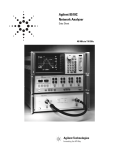
1
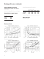
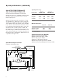
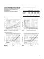
Agilent 8719D, 8720D, and 8722D
Network Analyzers
Data Sheet
50 MHZ – 20 GHZ
NETWORK ANALYZER
8720D
ACTIVE CHANNEL
ENTRY
RESPONSE
STIMULUS
PORT 1
INSTRUMENT STATE
R CHANNEL
PORT 2
8719D 50 MHz to 13.5 GHz
8720D 50 MHz to 20 GHz
8722D 50 MHz to 40 GHz
Table of Contents
2
3
3, 4, 5
6, 7, 8
9
10
11
12
13
15
22
24
Definitions and test conditions
System performance
Instruments with multiple options
Standard (no options)
Standard Instrument Performance
Option 400 (four samplers for TRL)
Also includes these configurations combined with
Options 089 and/or 012
Option 007 (mechanical switch)
Option 007/085 Performance
Option 085 (high power)
Also includes these configurations combined with
Options 089 and/or 012
Option 012
Option 089
Specifications and characteristics
Measurement throughput summary
Analyzer options
Capabilities
Software
Accessories
Definitions and Test Conditions
This data sheet provides two types of performance
information:
• System Specifications
• Supplemental Characteristics
System specifications describe the instrument’s warranted performance over the temperature range of
23 °C ± 3 °C (except where noted).
Supplemental characteristics describe the instrument’s
non-warranted performance parameters.
Reflection measurement uncertainty is plotted as a
function of S11 (reflection coefficient). Based on a
one-port calibration, using specified calibration kit,
with 10 Hz IF bandwidth and no averaging.
Assumes a one-port device (S21=S12=0).
Transmission measurement uncertainty is plotted
as a function of S21 (transmission gain/loss, in dB
from reference level). Assumes a well-matched
device (S11=S22=0). Based on a full two-port ShortOpen-Load-Thru calibration (including isolation
with averaging factor of 8), using specified calibration kit, with 10 Hz IF bandwidth and no averaging.
System dynamic range
These specifications apply to transmission measurements in the full frequency range at 10 Hz IF
BW with response and isolation correction or full
two-port calibration. Dynamic range is limited by
maximum receiver input level and the receiver’s
noise floor.
Measurement uncertainty
Curves show the worst-case magnitude and
phase uncertainty for reflection and transmission
measurements, after calibration. Calibration is the
process of measuring known standards from a calibration kit to characterize a network analyzer’s
systematic (repeatable) errors.
2
Measurement port characteristics
The characteristics indicate performance after
error-correction (full two-port calibration). The
performance accuracy is determined by the quality
of calibration standards and how well “known”
they are, plus system repeatability, stability, and
noise. Crosstalk is not shown, since isolation calibration will reduce crosstalk to the noise floor.
System performance
Agilent 8719D, 8720D with 3.5 mm test ports
Corrected measurement port characteristics
Standard, Options 400, 012, 089, or any combination of
these options
Calibration kit: Agilent 85052B, 3.5 mm with sliding loads
Cables: Agilent 85131F 3.5 mm flexible cable set
IF bandwidth: 10 Hz
Averaging: None (8 during isolation calibration)
System dynamic range
0.05 to 2 GHz
2 to 8 GHz
8 to 20 GHz
100 dB1
100 dB
100 dB
Frequency Range (GHz)
Directivity
Source Match
Load Match
Reflection Tracking
Transmission Tracking
0.05 to 0.5
0.5 to 2
2 to 8
8 to 20
48 dB
40 dB
48 dB
±0.006 dB
±0.017 dB
48 dB
40 dB
48 dB
±0.006 dB
±0.018 dB
44 dB
33 dB
44 dB
±0.006 dB
±0.066 dB
44 dB
31 dB
44 dB
±0.008 dB
±0.099 dB
Maximum output power
+5 dBm
1. Rolls off below 840 MHz to 77 dB at 50 MHz
Measurement uncertainty
Reflection measurements
Magnitude
Phase
Transmission measurements
Magnitude
Phase
3
System performance (continued)
Agilent 8722D with 2.4 mm test ports
Corrected measurement port characteristics
Standard, Options 400, 012, 089, or any combination
of these options.
Calibration kit: Agilent 85056A, 2.4 mm with sliding loads
Cables: Agilent 85133F 2.4 mm flexible cable set
IF bandwidth: 10 Hz
Averaging: None (8 during isolation calibration)
System dynamic range
0.05 to 2 GHz
2 to 8 GHz
8 to 20 GHz
20 to 40 GHz
93 dB1
93 dB
91 dB
80 dB
Frequency Range (GHz)
Directivity
Source Match
Load Match
Reflection Tracking
Transmission Tracking
Measurement uncertainty
Reflection measurements
Phase
Transmission measurements
Magnitude
4
2 to 8
8 to 20
20 to 40
42 dB
41 dB
42 dB
±0.005 dB
±0.020 dB
42 dB
38 dB
42 dB
±0.010 dB
±0.038 dB
42 dB
38 dB
42 dB
±0.010 dB
±0.048 dB
38 dB
33 dB
38 dB
±0.021 dB
±0.110 dB
Maximum output power
0.05 to 20 GHz: -5 dBm
20 to 40 GHz: -10 dBm
1. Rolls off below 840 MHz to 72 dB at 50 MHz
Magnitude
0.05 to 2
Phase
Agilent 8719D Option 400
Agilent 8720D Option 400
Agilent 8722D Option 400
Corrected measurement port characteristics
8719D/8720D Option 400
Frequency Range (GHz)
0.05 to 0.5 0.5 to 2
2 to 8
(with 3.5 mm test ports using TRL)
Includes instruments with Options 012 and/or 089
Calibration kit: Agilent 85052C, 3.5 mm for TRL
Cables: Agilent 85131F 3.5 mm flexible cable set
IF bandwidth: 10 Hz
Averaging: None (8 during isolation calibration)
Directivity
Source Match
Load Match
Reflection Tracking
Transmission Tracking
48 dB
40 dB
48 dB
±0.006 dB
±0.020 dB
48 dB
40 dB
48 dB
±0.006 dB
±0.026 dB
50 dB
50 dB
50 dB
±0.005 dB
±0.015 dB
8 to 20
50 dB
50 dB
50 dB
±0.005 dB
±0.019 dB
System dynamic range
Frequency Range
8719D/8720D
8722D
0.05 to 2 GHz
2 to 8 GHz
8 to 20 GHz
20 to 40 GHz
100 dB1
100 dB
100 dB
—
93 dB2
93 dB
91 dB
80 dB
1. Rolls off below 840 MHz to 77 dB at 50 MHz
2. Rolls off below 840 MHz to 67 dB at 50 MHz
Measurement uncertainty
Reflection measurements
Magnitude
8722D Option 400
Directivity
Source Match
Load Match
Reflection Tracking
Transmission Tracking
Frequency Range (GHz)
0.05 to 2
2 to 8
8 to 20
20 to 26.5
48 dB
40 dB
48 dB
±0.006 dB
±0.017 dB
50 dB
50 dB
50 dB
±0.005 dB
±0.023 dB
50 dB
50 dB
50 dB
±0.005 dB
±0.013 dB
50 dB
50 dB
50 dB
±0.005 dB
±0.016 dB
Maximum output power
8719D/8720D: +5 dBm
8722D (0.05 to 20 GHz): –5 dBm
(20 to 40 GHz): –10 dBm
Phase
Transmission measurements
Magnitude
Phase
5
System performance (continued)
Agilent 8719D, 8720D, 8722D Option 007
Agilent 8719D, 8720D, 8722D Option 085
System dynamic r ange
1
Includes instruments with Options 012 and/or 089
Frequency Range
Option 007
8719D/20D 8722D
Option 085
8719D/20D 8722D
Option 007 replaces the standard solid-state transfer switch with a mechanical switch to provide
higher output power.
0.05 GHz
0.05 to 2 GHz1
2 to 8 GHz
8 to 20 GHz
20 to 40 GHz
82 dB
105 dB
105 dB
105 dB
—
77 dB
100 dB
100 dB
100 dB
—
Option 085 adds internally controlled 0 to 55 dB
step attenuators (5 dB steps) in the receiver path
of both ports, an RF loop that allows the addition
of an amplifier before the transfer switch, and RF
loops after the switch that allow insertion of isolators, required for measurements above 1 watt. An
internal reference channel switch is added and
internal bias tees are deleted. This system is capable of full two-port calibrated measurements to 20
watts. Measurements up to 100 watts may be possible using specific configurations. Option 085 is not
compatible with Option 400.
Maximum output power
8719D/8720D
8722D (0.05 to 20 GHz)
8722D (20 to 40 GHz)
Source
Mechanical
transfer switch
Reference
switch
R
–55 dB
B
Samplers
+43 dBm max output
(20 watts)
Customer-supplied isolation
(for output above +30 dBm)
6
+43 dBm max input
(20 watts)
Amplifier
under test
Option 0852
+10 dBm
0 dBm
–5 dBm
+5 dBm
–5 dBm
–10 dBm
Supplemental characteristics (Option 085)
Maximum R-channel input level: 0 dBm
Minimum R-channel input level: –34 dBm
Maximum RF port input: +43 dBm
Attenuators: 55 dB maximum, 5 dB steps
Maximum test port power (no isolators): +30 dBm
Maximum test port power (with high power isolators): +43 dBm
RF in +43 dBm max
A
Option 007
2. With jumper cable installed between RF out and RF in ports,
i.e. no external amplification.
Customer-supplied
booster amplifier and coupler
–55 dB
67 dB
93 dB
93 dB
91 dB
77 dB
1. Rolls off below 840 MHz to specified value at 50 MHz
Option 085 block diagram and example
high power measurement setup
RF out
72 dB
98 dB
98 dB
96 dB
85 dB
Ref input
0 dBm max
Agilent 8719D or 8720D with Option 007 or 085
Calibration kit: Agilent 85052B 3.5 mm with sliding loads
Cables: Agilent 85131F 3.5 mm flexible cable set
IF bandwidth: 10 Hz
Averaging: None (8 during isolation calibration)
Corrected measurement port characteristics
Frequency Range (GHz)
Directivity
Source Match
Load Match
Reflection Tracking
Transmission Tracking
0.05 to 0.5
0.5 to 2
2 to 8
8 to 20
48 dB
40 dB
48 dB
±0.006 dB
±0.011 dB
48 dB
39 dB
45 dB
±0.010 dB
±0.016 dB
44 dB
32 dB
38 dB
±0.030 dB
±0.070 dB
44 dB
30 dB
37 dB
±0.031 dB
±0.122 dB
Measurement uncertainty
Reflection measurements
Magnitude
Phase
Transmission measurements
Magnitude
Phase
7
System performance (continued)
Agilent 8722D with Option 007 or 085
Corrected measurement port characteristics
Calibration kit: Agilent 85052A 2.4 mm with sliding loads
Cables: Agilent 85131F 2.4 mm flexible cable set
IF bandwidth: 10 Hz
Averaging: None (8 during isolation calibration)
Frequency Range (GHz)
Directivity
Source Match
Load Match
Reflection Tracking
Transmission Tracking
Measurement uncertainty
Reflection measurements
Magnitude
Phase
Transmission measurements
Magnitude
8
Phase
0.05 to 2
2 to 8
8 to 20
20 to 40
42 dB
40 dB
41 dB
±0.011 dB
±0.019 dB
42 dB
35 dB
48 dB
±0.037 dB
±0.054 dB
42 dB
34 dB
37 dB
±0.039 dB
±0.082 dB
38 dB
31 dB
35 dB
±0.047 dB
±0.145 dB
Option 012
Supplemental characteristics (Option 012)
Option 012 adds RF loops that provide direct
access to the A and B samplers in the port 1 and
port 2 receivers. This allows transmission measurements that bypass the receiver coupler for
improved signal-to-noise and sensitivity. The system
is capable of antenna measurements to –110 dBm at
40 GHz, and filter rejection measurements to 120 dB.
Use of multiple antennae provides improved signalto-noise for free space transmission and reflection
measurements. The RF loops can also be used to
integrate components into the test set. Adding a
20 dB attenuator increases the test port 0.1 dB
compression level to +30 dBm. With front panel
jumpers installed, the system operates as a standard system and meets standard instrument specifications.
Frequency Range (GHz)
0.05 to 0.5 0.5 to 2
2 to 8
8 to 20
20 to 40
Compression1
Test Port 1,2
20 dB
16 dB
15 dB
8 dB
3 dB
Compression1
Direct
Sampler Input
2 dBm
1 dBm
0 dBm
-7 dBm
-12 dBm
Average
Noise Floor2
-125 dBm
-125 dBm -125 dBm -123 dBm -120 dBm
Receiver
Dynamic Range
127 dB
126 dB
125 dB
116 dB
108 dB
1. Input power level that causes 0.1 dB compression in the receiver
2. 10 Hz IF BW
Option 012 test set block diagram
Measure filter rejection to –120 dB
Source
A
Transfer
Switch
B
Samplers
R
A
B
Measure amplifier output to +43 dBm
Samplers
Port 2 R channel
jumper
Port 1
A
Option 400 and 012 test set block diagram
B
Samplers
Source
Switch
Splitter
16 dB more sensitivity for antenna test. Improved
signal to noise for free space materials test.
R
A
A
B
B
Samplers
R2
Samplers
Port 1
Port 2 R channel
jumper
9
System performance (continued)
Option 089
Analyzer’s guided test setup display
Option 089 adds frequency offset mode, allowing
the receiver to be offset from the source frequency.
This allows direct conversion loss measurement of
mixers without need for a reference mixer. RF and
IF frequencies must be within the specified operating range of the instrument. This test set modification adds an internal reference channel switch and
deletes the reference channel output. Firmware
guides the user through test setup. When not in
frequency offset mode, the system operates as a
standard system and meets standard instrument
specifications.
Supplemental characteristics (Option 089)
Reference (R) Input Level
Minimum
Maximum (for 0.1 dB compression)
Maximum (damage level)
8719D/8720D
8722D
-34 dBm
-7 dBm
0 dBm
-34 dBm
-12 dBm
0 dBm
Note: To utilize full instrument receiver dynamic range, measure test signal
at port 2. This configuration requires a power splitter and reference mixer
to provide a phase lock signal to the R channel input.
Option 089 test set block diagram
Source
Mechanical
transfer switch
Reference
switch
R
A
B
Samplers
R channel
input
Filter
RF IF
Mixer
LO
under test
LO source
10
Specifications and characteristics
Description
Frequency Characteristics
Range
8719D
8720D
8722D
Accuracy (at 23 °C ± 3 °C)
Stability
0 °C to 55 °C
Option 1D5
Per year (aging)
Option 1D5
Resolution
System Characteristics
Maximum Input Level
Damage Level (test port)
Reference (F) Input Level (Option 089)
Maximum
8719D/8720D
8722D
Minimum
8719D/8720D/8722D
High Level Trace Noise2
Magnitude (zero-peak)
0.05 to 13.5 GHz
13.5 to 20 GHz
20 to 40 GHz
Phase (zero-peak)
0.05 to 13.5 GHz
13.5 to 20 GHz
20 to 40 GHz
Spectral Purity Characteristics
Harmonics at maximum output level
Phase Noise
to 60 kHz from carrier at 2 GHz
to 60 kHz from carrier at 20 GHz
Nonharmonic Spurious Signals
at 100 kHz offset
at 200 kHz offset
at >200 kHz offset
Specification
Code
0.05 to 13.51 GHz
0.05 to 20.05 GHz
0.05 to 40 GHz
±10 ppm
S-1
S-1
S-1
S-1
±7.5 ppm
±0.05 ppm
±3 ppm
±0.5 ppm
1 Hz
C
C
C
C
S-3
30 dBm
C
–7 dBm
–12 dBm
C
C
–34 dBm
C
0.03 dB
0.04 dB
0.15 dB
C
C
C
0.3°
0.4°
1.5°
C
C
C
<–15 dBc
C
<–55 dBc
<–35 dBc
C
C
<–40 dBc
<–45 dBc
<–65 dBc
C
C
C
Description
Power Characteristics
Power Range
8719D/8720D
8722D
0.05 to 20 GHz
20 to 40 GHz
Maximum Output Power
8719D/8720D (Standard, Options. 085, 400)
8719D/8720D (Option 007)
8722D (Standard, Options 085, 400)
0.05 to 20 GHz
20 to 40 GHz
8722D (Option 007)
0.05 to 20 GHz
20 to 40 GHz
Resolution
Flatness (at 5 dB below maximum output power)
8719D/8720D
8722D
Power Sweep Range
8719D
8720D
8722D
Power Linearity
±5 dB from reference
–10 dB from reference
+10 dB1 from reference
Test Reference Power
8719D/8720D (Standard, Options 085, 400)
8719D/8720D (Option 007)
8722D (Standard, Options 085, 400)
8722D (Option 007)
Specification
Code
75 dB
C
70 dB
65 dB
C
C
+5 dBm
+10 dBm
C
C
–5 dBm
–10 dBm
C
C
0 dBm
–5 dBm
0.01 dB
C
C
S-3
±2 dB
±3 dB
S-1
S-1
20 dB
20 dB
15 dB
S-3
S-3
S-3
±0.35 dB
±0.6 dB
±1 dB
S-1
S-1
S-1
–5 dBm
0 dBm
–10 dBm
S-3
S-3
S-3
Frequency Range (GHz)
Description
0.055
0.05 to 25 2 to 8
8 to 20
System Characteristics
Dynamic Range3
8719D/8720D
(Standard, Options 085, 400)
8719D/8720D (Option 007)
8722D (Standard4, Options 085, 400)
8722D (Option 007)
Receiver 0.1 dB Compression Input Level7
77 dB
82 dB
67 dB
72 dB
20 dBm
100 dB
105 dB
93 dB
98 dB
16 dBm
100 dB
105 dB
91 dB
96 dB
8 dBm
100 dB
105 dB
93 dB
98 dB
15 dBm
1. Does not apply to 8722D.
2. Trace noise is defined as variation of a high signal level trace due to noise. The
value given represents a noise variation that is three standard deviations away
from the trace’s mean value as measured in a 3 kHz IF bandwidth in th fast
sweep mode (STEP SWP OFF).
3. The dynamic range specifications apply to transmission measurements using
10 Hz IF BW and response and isolation correction or full two-port correction.
Dynamic range is limited by the maximum test port power and the receiver’s
noise floor.
4. With 85133E flexible cable on test port.
5. Rolls off below 840 MHz to specified value at 50 MHz.
6. 77 dB for Option 085.
7. For Option 012 direct sampler input compression levels, refer to page 9.
20 to 40
Code
80 dB6
85 dB
3 dBm
S-1
S-1
S-1
S-1
C
S-1: This performance parameter is verifiable using performance tests documented in
the service manual.
S-2: Due to limitations on available industry standards, the guaranteed performance
of the instrument cannot be verified outside the factory. Field procedures can
verify performance with a confidence prescribed by available standards.
S-3: These specifications are generally digital functions or are mathematically
derived from tested specifications, and can therefore be verified by functional
pass/fail testing.
C: Non-warranted performance characteristics are intended to provide information
useful in applying the instrument. Performance characteristics are representative of most instruments, though not necessarily tested in each unit. Not field
tested.
11
Measurement throughput summary
Full frequency band sweep time (ms)1
Number of Points
Measurement
51
201
401
1601
(Stepped mode/Swept mode)
Single Band Sweep (10 to 12 GHz)
Uncorrected
170/56
One-port calibration2
170/56
Two-port calibration3
331/100
523/93
523/93
1053/173
999/143
999/143
2024/272
3866/443
3866/443
7880/872
Agilent 8719D Full Sweep (0.05 to 13.5 GHz)
Uncorrected
612/496
1055/589 1539/651 4371/951
One-port calibration2
612/496
1055/589 1539/651 4371/951
Two-port calibration3
1217/977 2118/1166 3100/1287 8911/1892
Agilent 8720D Full Sweep (0.05 to 20 GHz)
Uncorrected
585/447
1068/580 1548/637 4386/939
One-port calibration2
585/447
1068/580 1548/637 4386/939
Two-port calibration3
1162/880 2144/1147 3123/1263 8942/1865
Agilent 8722D Full Sweep (0.05 to 40 GHz)
Uncorrected
760/581
1281/696 1733/713 4649/995
One-port calibration2
760/581
1281/696 1733/713 4649/995
Two-port calibration3
1510/1144 2572/1376 3497/1414 9478/1976
Time Domain Conversion4 13
44
90
387
GPIB Data Transfer5
Binary (Internal)
18
25
61
21
30
181
31
48
355
89
153
1391
13
IEEE754 floating point format
32 bit
14
64 bit
16
ASCII
52
1. All values are typical.
2. S11 one-port calibration, with a 6 kHz IF bandwidth. Includes system retrace time.
Time domain gating is assumed off.
3. S21 measurement with full two-port calibration, using a 6 kHz IF bandwidth.
Includes system retrace time and RF switching time. Time domain gating is
assumed off.
4. Option 010 only, gating and error-correction are off. Does not include sweep time.
5. Measured with an HP Omnibook 5500 133 Pentium computer.
12
Analyzer options
Option 010 time domain
With the time domain option, data from transmission or reflection measurements in the frequency
domain are converted to the time domain using a
Fourier transformation technique (chirp Z) and
presented on the display. The time domain response
shows the measured parameter value versus time.
Markers may also be displayed in electrical length
(or physical length if the relative propagation
velocity is entered).
Time stimulus modes
Standard stimulus
Two types of time excitation stimulus waveforms
can be simulated during the transformations, a
step and an impulse.
External stimulus
Other time excitation stimulus waveforms can be
accomplished using an external controller.
Low pass step
This stimulus, similar to a traditional time domain
reflectometer (TDR) stimulus waveform, is used to
measure low pass devices. The frequency domain
data should extend from DC (extrapolated value) to
a higher value, the upper limit being defined by the
test configuration used. The time domain response
shows the parameter value versus time (multiply
by the speed of light, c, to obtain electrical length
or by c and Vrel to obtain physical length). The step
response is typically used for reflection measurements only.
Low pass impulse
This stimulus is also used to measure low pass
devices. The frequency domain data should extend
from DC (extrapolated value) to a higher value, the
maximum frequency determined by the test configuration. The time domain response shows changes
in the parameter value versus time. The impulse
response can be used for reflection or transmission
measurements.
shows changes in the parameter values versus
time. Bandpass time domain responses are useful
for both reflection and transmission measurements.
Time domain range
The “alias-free” range over which the display is
free of response repetition, depends on the frequency span and the number of points. Range, in
nanoseconds, is determined by:
Range = 1/∆F = (Number of points in Frequency
Domain –1)/Frequency Span (GHz)
Range resolution
Time resolution of a time domain response (for example, 0.3 nanoseconds versus 0.307 nanoseconds).
Range –resolution = time span/(number of points –1)
Distance
Related to time by speed of light and relative velocity; in space, Vrel =1; for distance to response in
reflection measurement, multiply by 1/2.
Distance = 3 x 10⁸ m/sec x Vrel x Time
Windows
The windowing function can be used to modify (filter) the frequency domain data and thereby reduce
overshoot and ringing in the time domain response.
Three types of windows are available—minimum,
normal, and maximum.
Gating
The gating function can be used to selectively
remove reflection or transmission time domain
responses. In converting back to the frequency
domain the effects of the responses outside the
gate are removed. The location and span of the
gate can be controlled by either setting the center
position and time span of the gate, or by setting
the start and stop time of the gate.
Bandpass impulse
The bandpass impulse simulates a pulsed RF signal
(with an impulse envelope) and is used to measure
the time domain response of band-limited devices.
The start and stop frequencies are selectable by
the user to any values within the limits of the test
set used. The bandpass time domain response also
13
Analyzer options (continued)
Option 085, high power system
Option lD5, high stability frequency reference
This option is designed to permit the measurement
of high power amplifiers at RF levels up to 20 Watts
(+43 dBm), with full two-port calibration. A switch
is added to the reference path so that booster
amplifier response can be ratioed out. To protect
the analyzer from high power levels, this option
allows the addition of isolators at both test ports
and includes internally controlled step attenuators
between couplers and samplers. Bias tees, isolators
and booster amplifiers are not included. Network
analyzers with option 085 can also be configured
to operate as standard instruments with degraded
power accuracy or as instruments capable of making single connection multiple measurements.
This option provides the analyzer with ±0.05 ppm
temperature stability from 0 °C to 60 °C (referenced to 25 °C).
Option 007, mechanical transfer switch
This option replaces the solid state transfer switch
with a mechanical switch in the test set, increasing
the test port power and dynamic range.
Option 089, frequency offset mode
This option adds the ability to offset the source
and receiver frequencies for frequency translated
measurements. This provides the instrument with
mixer measurement capability. It also provides a
graphical setup that allows easy configuration of
your measurement.
14
Option 012, direct access receiver configuration
This option provides front panel access to the A
and B samplers for improved receiver sensitivity.
Option 012 improves signal-to-noise in free space
materials measurements with the use of multiple
antennas. Direct connection of the reflection
antennas to the A and B samplers eliminates internal reflections of the transmitted signal in the
reflection path, improving the signal to noise ratio.
Option 012 also allows you to add attenuators
between the couplers and samplers, increasing the
power handling capability of the instrument.
Option 400, fourth sampler
and TRL calibration firmware
This option converts the built-in test set to a foursampler configuration, allowing TRL calibration.
This provides the highest accuracy for non-coaxial
environments, such as on-wafer probing, in-fixture
or waveguide measurements.
Capabilities
Measurement capabilities
Number of measurement channels
2; each fully independent
Parameters
S11: Forward reflection (input match)
S21: Forward transmission (insertion loss/gain/phase)
S12: Reverse transmission (reverse isolation)
S22: Reverse reflection (output match)
A, B, R: Receiver signal level
A/R, B/R, A/B: Ratioed receiver signals
Auxiliary Input: DC voltage on AUX INPUT
Parameter conversion
Z – Reflection: equivalent parallel impedance
Y – Reflection: equivalent parallel admittance
Z – Transmission: equivalent series impedance
Y – Transmission: equivalent series admittance
1/S: complex inverse of S-parameters
Display formats
Cartesian
Log/linear magnitude, phase, group delay, SWR,
real and imaginary
Smith chart
Log/linear magnitude and phase, R+jX, G+jB, or real/imaginary markers
Polar
Linear/log magnitude, phase, or real and
imaginary markers
Markers
Number of markers
5 per channel; 1 “active” per channel; can be coupled
(same stimulus in both channels) or uncoupled
(independent stimulus in each channel).
Displayed marker values
All activated markers with both stimulus and
response values are displayed; with dual-channel
uncoupled, can display up to 10 markers; all but
active marker replaced by bandwidths or statistics,
when enabled.
Stimulus resolution
Discrete (actual measurement points) or continuous (linearly interpolated between points, with 1 Hz
resolution).
Delta markers
Displays difference in both stimulus (e.g. frequency)
and response (e.g. dB) between active marker and
reference marker; reference marker may be any of
five markers, or a sixth fixed marker given any
arbitrary position on display.
Polar format markers
Linear magnitude and phase; log magnitude (dB)
and phase; real and imaginary.
Smith chart format markers
Linear magnitude and phase; log magnitude (dB)
and phase; real and imaginary (R+jI); complex
impedance (R+jX); complex admittance (G+jB).
Search
Finds maximum, minimum, or target value.
Bandwidth
Finds and displays center frequency, bandwidth at
a user-defined level (for example, –3 dB), Q factor,
and shape factor (ratio of 60 dB and 6 dB bandwidths); updates while tuning with tracking enabled;
valid for band-pass or band-reject (notch) filters.
Statistics
Calculates and displays mean, standard deviation,
and peak-to-peak deviation of trace; active between
two markers or over entire trace.
Tracking
Performs new search (min/max/target) at end of
each sweep; if disabled, occurs once on demand.
Marker-to functions
Set start, stop or center to active marker stimulus
values; set span to active and delta marker stimulus values; set reference to active marker response
value; set electrical delay to active marker phase
response value.
Group delay characteristics
Group delay is computed by measuring the phase
change within a specified frequency step (determined by the frequency span, and the number of
points per sweep).
Aperture
Selectable. Maximum aperture: 20% of frequency
span. Minimum aperture: (frequency span)/(number of points–1).
Range
The maximum delay is limited to measuring no
more than 180° of phase change within the minimum aperture. Range= 1/(2 x minimum aperture).
Accuracy
In general, the following formula can be used to
determine the accuracy, in seconds, of a specific
group delay measurement:
±(0.003 x Phase accuracy(deg))/Aperture(Hz).
15
Capabilities (continued)
Source control
Sweep limits
Set start/stop or center/span of the stimulus
parameter (frequency, power, time) directly
through the source control keys and the control
knob, the step keys, or the data entry keyboard.
Sweep type
Set a linear or logarithmic sweep, an arbitrarily
defined frequency list, a power sweep, or a CW
(single frequency) type of sweep.
Fast swept list
Define up to 30 different subsweep frequency
ranges in any combination of CW, CW-delta F, or
start-stop sweep modes. Set test-port power levels
and IF bandwidth independently for each segment.
Measured number of points per sweep
Linear frequency: choose 3, 11, 21, 51, 101, 201,
401, 801, 1601 points.
Source coupling
Set a coupled channel sweep (same stimulus conditions on both channels) or an uncoupled channel
sweep (ind ependent stimulus conditions).
Chop/alternate sweeps
Select whether to alternately or simultaneously
(chop) measure channels when measuring with
two-port calibration. Chop mode is faster, while
alternate mode optimizes dynamic range. The
default is chop mode.
Sweep time
Set sweep time in seconds, minutes, or hours.
Minimum sweep time is dependent on number of
data points per sweep and selected IF bandwidth.
Auto sweep time
Select auto sweep time by entering zero seconds
sweep time. The analyzer will sweep at the minimum sweep time for any subsequently selected
stimulus conditions. Auto sweep time is the default
condition.
Sweep trigger
Set to either continuous, hold, single, group sweep,
or external trigger. Set external trigger to take a
complete sweep or to measure individual points in
a frequency, power, or list sweep.
Power
Control the test port signal by setting the internal
attenuator over a 70 dB range. Power trip automatically reduces source power to its minimum value
when excessive signal levels are incident on the
16
receiver test port. A caution message is also displayed.
Source power range differs depending on the selected
options. Power slope can be set in dBm/GHz.
Continuous switching
Continuously switches the RF output between port
1 and port 2; enables simultaneous active display
of forward and reverse parameters.
Power meter calibration
Description
Use a power meter to set leveled input or output
power at the device under test at a single point or
an entire sweep. With an Agilent 436A, 437B, or
438A power meter connected, the calibration
sweep measures the actual test port power. After
the calibration is enabled, the internal RF source
power is adjusted (within the range of –85 to +10 dBm)
to achieve the selected power at the input of the
device under test rather than at the test port output. GPIB control of the power meter for normalization or leveling is built-in. Logarithmic, linear,
CW, and list sweeps can be calibrated.
Update Calibration
Select continuous leveling (requires a power splitter)
by measuring and updating source power on each
sweep or use a correction table (to modify source
power) which is created with an initial single sweep.
Number of readings
Make single or multiple power meter readings at
each frequency.
Data accuracy enhancement
Description
Measurement calibration is the process that significantly reduces measurement uncertainty due to
system directivity, source and load match, tracking
and crosstalk. A wide range of calibrations are
available for the Agilent 8719D/20D/22D. Full twoport calibration removes all the systematic errors,
resulting in the most accurate measurements.
Frequency response
Simultaneous magnitude and phase correction of
frequency response errors for either reflection or
transmission measurements. Requires a short or
open circuit termination (reflection), or a through
connection (transmission).
Response and isolation
Compensates for frequency response and directivity
(reflection) or frequency response and crosstalk
errors. Requires an open, short, and load circuit
termination (reflection) and a through connection
and load termination (transmission).
One-port calibration
Uses test set port 1, or port 2, or both to correct
for directivity, frequency response, and source
match errors. Requires open, short, and load.
Two-port calibration
Compensates for directivity, source match, reflection frequency response, load match, transmission
frequency response, and crosstalk. Crosstalk calibration can be eliminated. Requires open, short,
and load terminations for both ports plus a
through connection.
TRL*/LRM* calibration
Compensates for directivity, reflection and transmission frequency response, and crosstalk in both
the forward and reverse directions. Especially suitable for calibrating non-coaxial environments, such
as in test fixtures. Requires through, reflect, and
line or match standards. TRL*/LRM* is a special
implementation of TRL/LRM calibration modified
for the three-sampler receiver in the standard
Agilent 8719D/20D/22D.
TRL/LRM calibration
With Option 400 (four-sampler receiver). TRL/LRM
provides the highest accuracy for non-coaxial test
environments such as in fixture, on-wafer or in
waveguide. Compensates for directivity, reflection
and transmission frequency response, and
crosstalk in both forward and reverse directions.
One-path, two-port calibration
Provides a full two-port error corrected measurement when the device under test is turned around
and measured in both directions.
Calibration Features
Fast two-port
Compensates for 12-terms, similar to full two-port,
except that 2 of 4 raw parameters (forward or reverse)
are continuously re-measured while the remaining 2
are periodically updated at a user-selectable rate.
Improves update rate for tuning, and reduces unnecessary wear on transfer switch in Option 007. [Meas] key
or contact closure at rear panel foot switch connector
causes full two-port update.
Interpolated error correction
With any type of accuracy enhancement applied,
interpolated mode recalculates the error coefficients when the test frequencies are changed. The
number of points can be increased or decreased
and the start/stop frequencies can be changed, but
the resulting frequency range must be within the
original calibration frequency range. System performance is not specified for measurements with
interpolated error correction applied.
Set Zo
Redefine the characteristic impedance of a measurement to a value other than 50 or 75 ohms.
Velocity factor
Enter the velocity factor of your propagation medium to
convert equivalent electrical length to physical length.
Electrical delay
Add or subtract delay (linear phase slope), up to
+10 µs, similar to “line stretchers,” both coax or
wave-guide (dispersive) modes. Secondary readout
in distance computed from velocity factor.
Reference plane extension
Redefine the reference plane after calibration. A
new reference plane is defined in seconds of delay
from the test port and ranges between ±l seconds.
Similar to electrical delay, but applied appropriately to each of four parameters.
Select default calibration kit
Select from a list of standard calibration kits: 7 mm,
3.5 mm, Type-N 50 ohm, Type-N 75 ohm, 2.4 mm,
2.92 mm, and 3.5 mm TRL. You can also define the
standards (for example, open circuit capacitance
coefficients, offset short length, or fixed loads) of a
user-defined kit.
Segmented calibration
Calibration remains valid for any frequency segment (in frequency list mode), after calibrating all
segments with a single calibration.
Receiver power calibration
Adjusts nonratioed receiver inputs to absolute (nonratioed) power level. Displays absolute power in dBm.
Requires reference sweep of known source power.
Data averaging
IF bandwidth
The IF bandwidth is selectable from 6 kHz to 10 Hz
bandwidth to reduce the effective displayed noise
floor of the instrument.
Weighted sweep-to-sweep averaging
Averages vector data on each successive sweep.
A(n) = S(n)/F + (1–1/F) x A(N–1) where A(n) is the
current average, S(n) is the current input signal
and F is the averaging factor. Averaging factors
range from 1 to 999.
Trace smoothing
Similar to video filtering, this function computes
the moving average of adjacent data points.
Smoothing aperture defines the trace width (number of points) to be averaged, and ranges from
0.25% to 20% of the trace width. This function also
sets the aperture for group delay measurements.
17
Capabilities (continued)
Display control
Save/Recall storage
Display formats
Single channel dual channel overlay (both traces
on one graticule), dual channel split (each trace on
separate graticules).
Instrument state
Up to 31 instrument states can be stored internally
or recalled via the SAVE/RECALL menu. Instrument
states include all control settings, active limit lines,
active list frequency tables, memory trace data,
active calibration coefficients, and custom display
titles. Storage is in non-volatile memory.
Trace functions
Display data
Display current measurement data, memory data, or
current measurement and memory data simultaneously.
Trace math
Vector division or subtraction of current linear
measurement values and memory data.
Display annotations
Start/stop, center/span, CW frequency, source
level, scale/div, reference level, marker data, softkey functions, warning and caution messages, trace
identification, and pass/fail indication.
Reference position
Ranges from the 0 (bottom) to 10 (top) graticule
position.
Autoscale
Automatically selects scale resolution and reference value to center the trace on the display graticules for easy viewing.
Electrical delay
Offset measured phase or group delay by a defined
amount of electrical delay, in seconds. Operates
similarly to an electronic line stretcher. Amount of
electrical delay can range between ±l seconds.
Frequency blanking
Blank out all frequency information on the display.
Requires an instrument preset to re-enable frequency information on the display.
Title
Add custom titles (49 characters maximum) to the
displayed measurement. Titles will be plotted when
making hardcopies. Titles can also be used to display operator messages or prompts for a manual
adjustment during a test sequence.
Adjust display
Control the intensity and background intensity values of the display. Also, customize the color, value,
and brightness of the data traces, memory traces,
reference lines, graticules, text, and warning messages. Default colors can be recalled along with
one set of user-defined display values. Control is in
% of full range.
18
Test sequences
Six measurement sequences can be stored or
recalled via the sequencing menu. Sequences may
also be recalled from Preset menu. Sequence register 6 is part of non-volatile storage and is not erased
during a power cycle. If sequence 6 is titled AUTO, it
will be executed when power is switched on.
Disk drive
Data, instrument states (including calibration
data), user graphics, data plots (HP-GL commands),
and test sequences can be stored on disk, using the
analyzer’s built-in disk drive or any external disk
drive with command subset CS/80. Data files can
be stored in MS-DOS format or Hewlett-Packard’s
standard LIF format in binary or ASCII formats
(compatible with the Agilent 85150A microwave
design system). A disk to be used for data storage
can be initialized directly by the analyzer.
Data hardcopy
Data plotting
Hard copy plots are automatically produced with
HP-GL compatible graphics printers such as the HP
DeskJet or LaserJet (in single color or multi-color
format). The analyzer provides Centronics, RS-232C,
and GPIB interfaces.
Configure plots
Configure plots completely from the network analyzer by defining pen color and line type for data,
text markers, graticules, and memory traces.
Functions
Plot trace(s), graticule(s), markers(s), or text
including operating and system parameters.
Quadrants
Plot entire display fullpage sized or in one of four
different quadrants of the plotter paper.
Data listings
Printouts of instrument data are directly produced
with a printer such as the HP DeskJet 520, LaserJet,
or 560C or PaintJet 3630A. Select a standard (single color) or color print. Printouts can include
either the graphical display image (excluding softkey label), or lists of numeric data; one line per
stimulus point, with up to five columns defined by
currently active parameters.
System Capabilities
Test sequences
Limit lines
Define test limit lines that appear on the display
for go/no go testing. Lines may be any combination
of horizontal, sloping lines, or discrete data points.
Limit test TTL output available for external control
or indication.
Description
Create, edit, save, or recall a series of front-panel
keystrokes to automate a measurement. Each of
the six sequence registers can hold approximately
200 instructions. Create or edit a sequence by
selecting the sequence menu and then simply performing the front-panel keystrokes that would normally be used to make a manual measurement.
Test sequences may contain basic stimulus and
measurement functions (frequency, power, parameter, format, scale) advanced operations (time
domain, limit testing, display marker values), and
basic logical branching (for example, IF limit test
fails DO sequence 5). Completed sequences are
then saved and can be executed when you are
ready to repeat the test.
Operating parameters
Display, print or plot current instrument operating
parameters.
Transform
When time domain (Option 010) is present, selects
the time domain transform menu.
Instrument mode
Select external source, tuned receiver, or frequency
offset mode.
External source mode
The receiver (input R) detects and phase-locks to
any externally generated CW signal. Receiver
inputs A and B will measure this same frequency
for comparison or tracking measurements.
Auto
The input signal frequency is counted and displayed.
Manual
Measures the input signal closest to the frequency
specified by the user (within –0.5 to +5 MHz).
Tuned receiver
Tunes the receiver for a synthesized CW input signal at a precisely specified frequency. The time
bases of the external RF source or sources must be
tied to the external reference input of the network
analyzer (rear panel BNC). The built-in RF source
is not used.
Frequency offset on/off
Sets the RF source to be swept at a frequency that
is offset from the receiver as required in a swept
RF/IF, fixed LO, mixer test. The maximum delay
between the RF source and the R channel input is
0.3 microseconds. Frequency offset mode requires
RF and IF frequencies to be in the specific range of
the instrument.
Storage
Test sequences can be stored internally in RAM, to
an internal or external disk drive, or loaded from a
computer over the GPIB interface. Sequence 6 is
saved in non-volatile storage and can be used as an
autostart routine when titled AUTO.
Branching
Branch to another sequence on limit test pass/fail
or the loop counter value. Subroutines are also
possible via GOSUB.
Other GPIB instruments
Send simple commands to GPIB instruments via
the title string.
Test sequence BNC output
Set TTL high or low on the analyzer rear panel output.
General purpose input/output
Read or write bits to the output port to control
external devices such as part handlers. Eight output and five input TTL lines are available on the
parallel port of the analyzer.
Other functions
Pause/continue, wait, title sequence, print
sequence, duplicate sequence, pause, and select.
Offset value
Set the offset frequency value.
Service menu
Select the desired service test, service diagnostic,
service, or verification mode.
19
Capabilities (continued)
GPIB (remote) programming
General characteristics
Interface
GPIB interface operates to IEEE 488-1978 and IEC
625 standards and IEEE 728-1982 recommended
practices.
Front panel connectors
Connector type
Agilent 8719D/8720D: 3.5 mm precision
Agilent 8722D: 2.4 mm precision
Addressing
The GPIB address of the analyzer can be verified
or set from the front panel via the local menu and
can range from 0 to 30 decimal (factory set at 16).
Impedance
50 ohms (nominal)
Pass control
Allows the analyzer to request control of the GPIB
(when an active controller is present) whenever it
needs to output to a plotter or printer.
System controller
Allows the analyzer to become a controller on the
GPIB to directly control a plotter or a printer.
Talker/listener
Allows the analyzer to become a GPIB talker/ listener when an external controller is present.
Transfer formats
Binary (internal 48-bit floating point complex format), ASCII and 32- or 64-bit IEEE 754 floating
point format.
User-accessible graphics
Using a subset of HP graphics language (HP-GL),
vector or text graphics may be written on the analyzer via GPIB. Up to 5 kbytes of data can be
stored at one time (4 bytes per vector, 2 bytes per
character).
Interface function codes
SHI, AHI, T6, L4, SRI, RLI, PPO, DC1, DT1, Cl, C2, C3, CIO, E2
Upgrades
Refer to Configuration Guide.
Security
Frequency blank
Blanks all frequency information from display,
including markers; requires FACTORY PRESET to
re-enable.
Reset memory
Writes binary zeros to all non-volatile memory registers, erasing all instrument state and calibration
data; used with PRESET.
20
Rear panel connectors
External reference frequency input (EXT REF INPUT)
Frequency: 1, 2, 5, and 10 MHz (±200 Hz at 10 MHz)
Level: –10 dBm to +20 dBm, characteristically
Impedance: 50 ohms
High-stability frequency reference output (Option 1D5)
Frequency: 10.0000 MHz
Frequency stability (0 °C to 55 °C): ±0.05 ppm
Daily aging rate (after 30 days): <3 x 10⁻⁹/day
Yearly aging rate: 0.5 ppm/year
Output: 0 dBm minimum
Nominal output impedance: 50 ohms
External auxiliary input (AUX INPUT)
Input voltage limits: –10 V to +10 V
External AM input (EXT AM)
±l volt into a 5 kΩ resistor, 1 kHz maximum, resulting
in approximately 8 dB/volt amplitude modulation.
External trigger (EXT TRIGGER)
Triggers on a negative TTL transition or contact
closure to ground.
Test sequence output (TEST SEQ)
This connector outputs a TTL signal which can be
programmed by the user in a test sequence to be
high or low. By default, this output provides an endof-sweep TTL signal. (For use with part handlers.)
Limit test output (LIMIT TEST)
This connector outputs a TTL signal of the limit
test results. Pass: TTL high; Fail: TTL low.
Test port bias input (except Option 085)
Maximum voltage: +30 Vdc
Maximum current (no degradation in RF specifications):
±200 mA
Maximum current: ±lA
External monitor: VGA video output
This connector drives external VGA monitors.
GPIB
This connector allows communication with compatible devices including external controllers,
printers, plotters, disk drives, and power meters.
Environmental Characteristics
Parallel port
This connector is used with parallel (or Centronics
interface) peripherals such as printers and plotters. It can also be used as a general purpose I/O
port, with control provided by test sequencing
functions.
General Conditions
RFI and EMI susceptibility
Defined by VADE 0730, CISPR Publication 11, and
FCC Class B Standards.
RS-232
This connector is used with serial peripherals such
as printers and plotters.
ESD (electrostatic discharge)
Must be eliminated by use of static-safe work procedures and an anti-static bench mat (such as
Agilent 92175T).
DIN keyboard
This connector is used for the optional AT compatible
keyboard for titles and remote front-panel operation.
Dust
The environment should be as dust-free as possible.
Internal memory
Typical data retention time with 3 V, 1.2 Ah battery:
At 25 °C: 11,904 days (32.6 years)
At 40 °C: 1244 days (3.4 years)
At 70 °C: 250 days (0.68 year)
Operating conditions
Operating temperature: 0 °C to 55 °C
Error-corrected temperature Range: ±1 °C of calibration
temperature
Humidity: 5% to 95% at 40 °C (noncondensing)
Altitude: 0 to 4500 meters (15,000 feet)
Line power
48 to 66 Hz, 115 V nominal (90 V to 132 V) or 230 V nominal
(198 V to 264 V), 280 VA maximum
Weight
Net: 25 kg (54 lb)
Shipping: 28 kg (61 lb)
Non-operating storage conditions
Temperature: –40 °C to +70 °C
Humidity: 0 to 90% relative at +65 IC (noncondensing)
Altitude: 0 to 15,240 meters (50,000 feet)
Cabinet dimensions
222 mm (H) x 425 mm (W) x 457 mm (D) (8.75 x 16.75 x 18 in)
(These dimensions exclude front and rear panel protrusions.)
Ventilation
Allow 100 mm (4 in.) around rear and sides.
TOP
457 mm
(18 inches)
425 mm
(16.75 inches)
REAR
222 mm
(8.75 inches)
SIDE
21
Software
Agilent 85071B Materials Measurement Software
Agilent 85070B Dielectric Probe Kit
Description
The 85071B software uses broadband S-parameter
measurements to determine the electromagnetic
properties of dielectric and magnetic materials.
The software calculates both the complex permittivity εr (or dielectric constant) and permeability
µ r, including loss factors. Depending on the network analyzer and fixtures used, measurements
can extend from 100 MHz to 110 GHz. The software
offers the choice of four algorithms, each designed
to address specific measurement needs.
Description
The 85070B dielectric probe kit allows convenient
non-destructive testing of materials using the
open-ended coaxial probe method. The probe,
together with its own dedicated software, determines the complex permittivity of a wide variety of
liquids, semi-solids, and solids. Since the probe kit
measures only permittivity, only non-magnetic
materials should be measured. Measurements are
efficient and cost-effective because the testing is
non-destructive and there is no need for sample
preparation or special fixtures.
Operating requirements
Standard: Requires MS-DOS on an HP Vectra (or any 100%compatible PC-AT computer) compatible with Microsoft
Windows 3.0 or higher with mouse. Requires >20 Mbyte
hard disk and >640 Kbytes RAM.
Option 300: Substitutes HP BASIC Software for the standard version for operation with HP 9000 series 300 controllers. Requires BASIC 5.0 or higher and 2 Mbytes of
RAM.
Performance summary
Frequency range: 100 MHz to 110 GHz (characteristically,
depending on network analyzer, fixture, and material).
Format: εr’, εr”, µ r’, µ r”, tan δ, tan δm, or Cole-Cole plots;
tabular listings of data.
Operating requirements
Standard: Requires MS-DOS on an HP Vectra (or any 100%compatible PC-AT computer) compatible with Microsoft
Windows 3.0 or higher with mouse. Requires >20 Mbyte
hard disk and >640 Kbytes RAM.
Option 300: Substitutes HP BASIC Software for the standard version for operation with HP 9000 series 300 controllers. Requires BASIC 5.0 or higher and 2 Mbytes of
RAM.
Performance summary
Frequency range: 200 MHz to 20 GHz (typical, depending on
network analyzer, fixture, and material).
Stimulus control: Frequency range, number-of-points, and
linear or log sweep.
Probe Temperature
Range: –40 °C to +200 °C
Rate: <10°C per minute
Calibration: The software can use any calibration including
a calibrated response gated in the time domain.
Format: εr’, εr”, tan δ, or Cole-Cole diagram in
linear format.
Accuracy: 1 to 2%
Stimulus control: Frequency range, number-of-points, and
linear or log sweep.
Fixture: The software works with simple transmission lines:
coaxial airlines, or rectangular waveguide containing a
cross-sectional sample of the material-under-test.
Data display: Displays current measurement data, and can
save/display 3 memory traces for comparison.
Data storage: Save/recall/export data via disk in
MS-DOS® ASCII format or HP BASIC BDAT format (HP LIF
binary).
Calibration: Guided, using open, short (included), and deionized water. Supports user-defined standards.
Accuracy
Dielectric constant, εr’: ±5%
Loss tangent, tan δ, εr”/εr’: ±0.05
Data display: Displays current measurement data, and can
save/display up to three memory traces for comparison.
Data storage: Save/recall/export data via disk in
MS-DOS® ASCII format or HP BASIC BDAT format (HP LIF
binary).
22
Accessories
A wide range of accessories support the Agilent
8720 family of network analyzers, including calibration kits, verification kits, cables and adapters
in both 7 mm, 3.5 mm, Type-N, and 2.4 mm coax
and in the standard waveguide bands. The standards used in the 3.5 mm, Type-N, and 2.4 mm calibration and verification kits use precision slotless
connectors (PSC-3.5, PSC-N, and PSC-2.4).
Calibration kits
Vector accuracy enhancement procedures require
that the systematic errors of the measurement system be characterized by measuring known devices
(standards) on the system over the frequency
range of interest. Agilent Technologies offers the
following types of calibration kits:
Standard calibration kits
Contain open circuits, short circuits, and both
fixed and sliding terminations in both sexes for all
connector types (except 7 mm, a sexless connector). Connector gauges are included in these kits
for maintaining each standard’s connector interface. Standard calibration kits that include RTL
adapters and devices are also available in 7 mm
and 3.5 mm connectors.
Precision calibration kits
Have precision 50Ω airline(s) for performing the
Thru-Reflect-Line (TRL) calibration. These kits also
contain the open circuit, short circuit, and fixed
terminations used for traditional open-short-load
calibration techniques.
Calibration kits
Cal Kit Type
and Name
Frequency
Range (GHz)
fmin–fmax
Connector
Type
Return Loss,
Fixed Load
Return Loss,
Sliding Load
Return
ResiduaI
Loss, Airline Directivity2
at fmax
at fmax
ResiduaI
Source Match2
at fmax
Precision
85052C
0.045 to 26.5
3.5 mm
≥46 dB, DC to 2 GHz
—
50 dB
50 dB
50 dB
Standard
85050B
85052B
85054B
85056A
0.045 to 18
0.045 to 26.5
0.045 to 18
0.045 to 50
7 mm
3.5 mm
Type-N
2.4 mm
≥52 dB, DC to 2 GHz
≥44 dB, DC to 3 GHz
≥48 dB, DC to 2 GHz
≥42 dB, DC to 4 GHz
≥52 dB, 2 to 18 GHz
≥44 dB, 3 to 26.5 GHz
≥42 dB, 2 to 18 GHz
≥36 dB at 50 GHz
—
—
—
—
45 dB
44 dB
42 dB
38 dB
30 dB
30 dB
30 dB
31 dB
Economy
85050D
85052D
85054D
85056D
85056K
0.045 to 18
0.045 to 26.5
0.045 to 18
0.045 to 50
0.045 to 40
7 mm
3.5 mm
Type-N
2.4 mm
2.92 mm
≥38 dB, DC to 18 GHz
≥30 dB at 26.5 GHz
≥34 dB at 18 GHz
≥26 dB at 50 GHz
≥26 dB at 40 GHz
—
—
—
—
—
—
—
—
—
—
36 dB
36 dB
34 dB
26 dB
25 dB
30 dB
29 dB
28 dB
23 dB
22 dB
Waveguide
X11644A1
P11644A1
K11644A1
R11644A
8.2 to 12.4
12.4 to 18
18 to 26.5
26.5 to 40
WR-90
WR-62
WR-42
WR-28
≥42 dB,8.2 to 12.4 GHz
≥42 dB,12.4 to 18 GHz
≥42 dB,18 to 26.5 GHz
—
50 dB
46 dB
40 dB
50 dB
50 dB
50 dB
30 dB
40 dB
40 dB
40 dB
30 dB
30 dB
30 dB
Electronic
85060A3
Option 001
85062A3
Option 001
85064A3
Option 001
1 to 18
0.45 to 2
1 to 26.5
0.45 to 2
1 to 18
0.45 to 2
7 mm
7 mm
3.5 mm
3.5 mm
Type-N
Type-N
—
—
—
—
—
—
—
—
—
—
—
—
—
—
—
—
—
—
44.5 dB
51 dB
41.5 dB
50.5 dB
44.5 dB
50 dB
39.5 dB
44.5 dB
35.5 dB
43.5 dB
39.5 dB
43.5 dB
1. Airline return loss, directivity, and source match are typical values for these calibration kits.
2. Residuals based on Agilent 8720D at fmax =20 GHz for 3.5 mm kits or on Agilent 8722D at fmax= 40 GHz for 2.4 mm kits.
3. Requires an Agilent 85060C control unit.
23
Economy calibration kits
Include the open circuit, short circuit, and fixed
termination standards but not sliding terminations
or gauges. Gauges can be ordered separately.
Waveguide calibration kits
Contain two coax-to-waveguide adapters with precision flanges, a flush short circuit, a precision
waveguide line section, and either sliding or fixed
terminations. They support calibration based on
TRL*, offset load, or short/offset-short/load/thru
methods.
Electronic calibration kits
Require an Agilent 85060C control unit for operation and Agilent 85060 series calibration modules
of the appropriate connector type. The calibration
modules is programmed by a control unit to present many different impedances to the test ports. A
full two-port calibration can be done with a single
connection. Each standard calibration kit contains
the two-port calibration module and a torque
wrench for proper connection. Options are available to add a lowband module to the kit, and to
change the sex of the connectors of the module.
Test port return cables
Test port cables are available in the 7 mm, 3.5 mm,
Type-N, and 2.4 mm connectors types. All cables
connect directly to the special ruggedized test port
of the network analyzer test port (NMD connector).
Agilent offers the following cable choices:
• Single cables in semi-rigid and flexible
• Cable set in semi-rigid and flexible
A single long cable with an appropriate test port
adapter is best for applications where the test
device requires a connection next to the test port
for mechanical rigidity. A set of cables offers the
flexibility required to position the test devices
away from the test set.
Semi-rigid cables offer excellent performance and
are suitable for applications where the connectors
of the test device are “in-line” or parallel. Flexible
cables are ideal for manufacturing environments
since they are more rugged and have a tighter
bending radius than semi-rigid cables. Semi-rigid
cables are warranted for 90 days; flexible cables
are warranted for 1 year.
Verification kits
Measuring known devices, other than the standards used in calibration, is an easy way to verify
the correct operation of an Agilent 8719D/20D/22D
network analyzer system. Agilent offers the following verification kits which contain precision
devices, with data traceable to NIST used to verify
the analyzer’s error-corrected measurement performance.
•
•
•
•
24
85051B 7 mm verification kit; 0.045 to 18 GHz
85055A Type-N verification kit; 0.045 to 18 GHz
85053B 3.5 mm verification kit; 0.045 to 26.5 GHz
85057B 2.4 mm verification kit; 0.045 to 50 GHz
Network Analyzer
Test Set
Device
Under
Test
Network Analyzer
Test Set
Test Port
Adapter
Cable Set
Single Cable
Device
Under
Test
Accessories (continued)
Test port return cable specifications
Connector Type
Frequency
(Test Port to Device) (GHz)
Length2
cm (inch)
Return
Loss
Insertion Loss
(dB) (f in GHz)
Stabillty1, 2
±Phase
±Magnitude (degrees)
DC to 26.5
81 (32)
≥17 dB
0.16 (f) +0.5
DC to 26.5
96.5 (38)
≥16 dB
<0.22 dB
0.16 (f) +0.8
DC to 18
81 (32)
≥17 dB
<0.06 dB
0.16 (f) +0.5
85132E Flexible Cable
3.5 mm3 to 7 mm
DC to 18
97.2 (38.25)
≥17 dB
0.43 √f +0.3
(2.5 dB at fmax)
0.35 √f +0.3
(2.1 dB at fmax)
0.35 √f +0.3
(1.8 dB at fmax)
0 35 √f +0.3
(1.8 dB at fmax)
<0.06 dB
85132C Semi-rigid Cable
3.5 mm3 to
PSC-3.5 mm (f)
3.5 mm3 to
PSC-3.5 mm (f)
3.5 mm3 to 7 mm
<0.22 dB
0.16 (f) +0.8
DC to 26.5
53 (21)
≥16 dB
0.30 √f +0.2
(1.8 dB at fmax)
<0.06 dB
0.16 (f) +0.5
DC to 26.5
62.2 (24.5)
≥16 dB
0.25 √f +0.2
(1.5 dB at fmax)
<0.12 dB
0.13 (f) +0.5
85132D Semi-rigid Cable Set
3.5 mm3 to
PSC-3.5 mm (f) or
3.5 mm3 (m)
3.5 mm3 to
PSC-3.5 mm (f) or
3.5 mm3 (m)
3.5 mm3 to 7 mm
DC to 18
53 (21 )
≥17 dB
<0.06 dB
0.16 (f) +0.5
85132F Flexible Cable Set
3.5 mm3 to 7 mm
DC to 18
62.9 (24.75)
≥17 dB
0.25 √f +0.2
(1.3 dB at fmax)
0.25 √f +0.2
(1.3 dB at fmax)
<0.12 dB
0.13 (f) +0.5
DC to 50
81 (32)
≥15 dB
0.18 (f)
DC to 50
113 (44)
≥12.5 dB
<0.25 dB
0.8 +0.16 (f)
DC to 26.5
81 (32)
≥16 dB
<0.06 dB
0.18 (f)
DC to 26.5
97.2 (38.25)
≥16 dB
<0.22 dB
0.16 (f) +0.8
DC to 18
81 (32)
≥17 dB
<0.06 dB
0.18 (f)
85135E Flexible Cable
2.4 mm3 to 7 mm
DC to 18
97.2 (38.25)
≥17 dB
0.84 √f +0.3
(5.6 dB at fmax)
0.58 √f +0.35
(4.45 dB at fmax)
0.46 √f +0.3
(2.7 dB at fmax)
0.46 √f +0.3
(2.7 dB at fmax)
0.46 √f +0.3
(2.25 dB at fmax)
0.46 √f +0.3
(2.25 dB at fmax)
<0.06 dB
85135C Semi-rigid Cable
2.4 mm3 to
PSC-2.4 mm (f)
2.4 mm3 to
PSC-2.4 mm (f)
2.4 mm3 to
PSC-3.5 mm (f)
2.4 mm3 to
PSC-3.5 mm (f)
2.4 mm3 to 7 mm
<0.22 dB
0.16 (f) +0.8
DC to 50
53 (21 )
≥15 dB
0.55 √f +0.2
(3.7 dB at fmax)
<0.06 dB
0.16 (f)
DC to 50
72 (28)
≥12.5 dB
0.48 √f +0.25
(3.64 dB at fmax)
<0.17 dB
0.8 +0.16 (f)
DC to 26.5
53 (21)
≥16 dB
0.31 √f +0.2
(1.8 dB at fmax)
<0.06 dB
0.18 (f)
DC to 26.5
62.9 (24.75)
≥16 dB
0.31 √f +0.2
(1.8B dB at fmax)
<0.12 dB
0.13 (f) +0.5
85135D Semi-rigid Cable Set
2.4 mm3 to
PSC-2.4 mm (f) or
2.4 mm3 (m)
2.4 mm3 to
PCS-2.4 mm(f) or
2.4 mm3 (m)
2.4 mm3 to
PSC-3.5 mm (f) or
3.5 mm3 (m)
2.4 mm3 to
PSC-3.5 mm (f) or
3.5 mm3 (m)
2.4 mm3 to 7 mm
DC to 18
53 (21)
≥17 dB
<0.06 dB
0.18 (f)
85135F Flexible Cable Set
2.4 mm3 to 7 mm
DC to 18
62.9 (24.75)
≥17 dB
0.31 √f +0.2
(1.5 dB at fmax)
0.31 √f +0.2
(1.5 dB at fmax)
<0.12 dB
0.13 (f) +0.5
Single cables for
8719D and 8720D (3.6 mm)
85131C Semi-rigid Cable
86131E Flexible Cable
Cable set for
8719D and 8720D (3.5 mm)
85131D Semi-rigid Cable Set
85131F Flexible Cable Set
Single cables for
8722D (2.4 mm)
85133C Semi-rigid Cable
85133E Flexible Cable
85134C Semi-rigid Cable
85134E Flexible Cable
Cable set for
8722D (2.4 mm)
85133D Semi-rigid Cable Set
85133F Flexible Cable Set
85134D Semi-rigid Cable Set
85134F Fiexibie Cable Set
1. Phase stability of semi-rigid/flexible cables is specified with a 90 degree bend and a 4"/3" radius.
2. Cable length and stability are supplemental characteristics.
3. Special rugged female connector specifically for connecting to the network analyzer test port, but does not mate with a standard male connector.
25
Test port adapter sets
The Agilent 85130 series test port adapter sets protect the test set port when connecting devices to
the test port. These adapters, listed below with the
single cables, convert the ruggedized test set port
to a connection mateable with the device under
test. Each set contains a male and a female
adapter.
Adapter sets
Adapter
Set
Connector Type
(Test Port to Device)
Frequency
(DC–fmax)
Return Loss
at fmax
85130C
85130D
3.5 mm1 to Type–N
3.5 mm1 to PSC-3.5 mm (f)
or 3.5 mm1 (m)
2.4 mm1 to 7 mm
2.4 mm1 to PSC-3.5 mm (f)
or 3.5 mm1 (m)
2.4 mm1 to PSC-2.4 mm (f)
or 2.4 mm1 (m)
DC to 18 GHz
DC to 26.5 GHz
≥28 dB
≥28 dB
DC to 18 GHz
DC to 26.5 GHz
≥26 dB
≥26 dB
DC to 50 GHz
≥23 dB
85130E
85130F
85130G
1. Special rugged female connector specifically for connecting to the network analyzer
test port, but does not mate with a standard male connector.
Equipment rack systems
Agilent 85043D Racked System Kit
The 85043D racked system kit is a rack standing
128 cm (50.5 in) high, with a width of 60 cm (24 in)
and a depth of 80 cm (32 in). Complete with support rails and AC power distribution (suitable for
50 to 60 Hz, 100 to 240 VAC), the kit includes rack
mounting hardware for all instruments. Thermal
design is such that no rack fan is needed.
Agilent 1181A System Testmobile
The 1181A system testmobile is a unit that provides mobility for instruments, test systems, and
workstations. It holds units up to 610 mm (24 in)
deep. The load capacity is up to 90 kg (200 lbs) on
the tilt tray and 227 kg (500 lb) total. The following
accessories are available for the test mobile:
•
•
•
•
•
•
•
•
35181A top mounted printer/plotter stand
35181B keyboard holder
35181C 3.5 inch high storage drawer
35181D work surface
35181E anti-static work mat
3518IG 5.25 inch high storage drawer
92199B power strip for US and Canada
92199E international power strip (IEC-320)
Agilent Technologies’ Test and Measurement Support, Services, and
Assistance
Agilent Technologies aims to maximize
the value you receive, while minimizing your risk and problems.
We strive to ensure that you get the test and measurement capabilities you paid for and obtain the support you need. Our extensive support resources and services can help you choose the
right Agilent products for your applications and apply them
successfully. Every instrument and system we sell has
a global warranty. Support is available
for at least five years beyond the production life of the product.
Two concepts underlie Agilent’s overall support policy: “Our
Promise” and “Your Advantage.”
Our Promise
“Our Promise” means your Agilent test and measurement equipment will meet its advertised performance and functionality.
When you are choosing new equipment, we will help you with
product information, including realistic performance specifications and practical recommendations from experienced test
engineers. When you use Agilent equipment, we can verify that
it works properly, help with product operation, and provide
basic measurement assistance for the use of specified capabilities, at no extra cost upon request. Many self-help tools are
available.
Your Advantage
“Your Advantage” means that Agilent offers a wide range of
additional expert test and measurement services, which you can
purchase according to your unique technical and business
needs. Solve problems efficiently and gain a competitive edge by
contracting with us for calibration, extra- cost upgrades, out-ofwarranty repairs, and on-site education and training, as well
as design, system integration, project management, and other
professional services. Experienced Agilent engineers and technicians worldwide can help you maximize your productivity, optimize the return on investment of your Agilent instruments and
systems, and obtain dependable measurement accuracy for the
life of those products.
Get assistance with all your
test and measurement needs at:
www.agilent.com/find/assist
Product specifications and descriptions in
this document subject to change without notice.
Copyright © 1998, 2000 Agilent Technologies
Printed in U.S.A. 5/00
5964-9133E