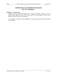
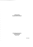
1
MODEL 3000
DIGITAL CAPACITANCE METER
Instruction and Service Manual
C LKINSTRUMENTS
MODEL 3000
DIGITAL CAPACITANCE METER
Operation and Calibration Manual
Serial Numbers
This manual applies directly to instruments with serial
numbers 10003 and up.
Serial Number: ___________
For technical assistance, contact
GLK INSTRUMENTS
Email: [email protected]
Website: www.glkinst.com
TABLE OF CONTENTS
Page
Section
I. Warranty
3
II.
Product Use Restrictions
3
III.
Return Material Authorization
3
IV.
Specifications
4
V.
Description
5
VI.
Initial Preparation
6
VII.
Operating Instructions
7
VIII.
Servicing Information
9
IX.
Calibration
9
X.
Revisions
10
XI.
Schematics and Parts Lists
10
I. WARRANTY
GLK Instruments products are warranted against defects in workmanship and materials under normal use
and service for one year from date of their shipment by GLK Instruments, except that components obtained from others are warranted only to the extent of the original manufacturers' warranties, if any. This
warranty does not extend to any products which have been repaired or altered by others. GLK Instruments' sole liability and the Purchaser's sole remedy under this warranty is limited to repairing or replacing defective products. The repair or replacement of defective products does not extend the warranty
period. This warranty does not apply to components or products which by the nature of the applications
are consumed in operation or which have a normal life inherently shorter than one year. Examples of
this are batteries, components or products exposed to nuclear radiation, or used in the measurement of
detection of explosions.
GLK Instruments shall not be liable for consequential damages under any
circumstances.
THE FOREGOING WARRANTY AND REMEDY ARE IN LIEU OF ALL OTHER REMEDIES AND ALL
OTHER WARRANTIES, WRITTEN OR ORAL, STATUTORY, EXPRESS, OR IMPLIED, INCLUDING
ANY WARRANTY OF MERCHANTABILITY OR FITNESS FOR A PARTICULAR PURPOSE.
II. PRODUCT USE RESTRICTIONS
GLK Instruments does not recommend the use of any of its products or the incorporation of any of its
products by second parties in their products in (a) life support applications where failure or malfunction of
the product can be reasonably expected to cause failure of the life support device or to significantly affect its safety or effectiveness, (b) any nuclear facility applications which including nuclear reactors and
devices designed or used in connection with the handling, processing packaging, preparation, utilization,
fabricating, alloying, storing, or disposal of fissionable material or waste products, (c) consumer applications where failure or malfunction of the product can be reasonably expected to cause injury, and (d) applications where failure or malfunction of the product can reasonably be expected to place the health and
safety of the general public in jeopardy. GLK Instruments will not knowingly sell its products for use in
such applications unless GLK Instruments receives in writing satisfactory assurances that (a) the risks of
injury or damage have been minimized, (b) the customer assumes all such risks, and (c) the liability of
GLK Instruments is adequately protected under the circumstances.
III. RETURN MATERIAL AUTHORIZATION
In the unlikely event that any of the products of GLK Instruments need repair, contact GLK Instruments
for a return material authorization (RMA) number.
3
IV. SPECIFICATIONS
(25°C unless specified otherwise)
Electrical
Capacitance range:
2.000 pF to 200.0 nF
Resolution:
0.001 pF to 0.1 nF
Display:
3 1/2 digit LCD
Accuracy with or without probes:
±(0.1 % of rdg. + 2 digits)
Measurement frequencies:
24 kHz (2 pF, 20 pF, 200 pF, 2 nF)
2.4 kHz (20 nF)
240 Hz (200 nF)
Offset adjustment:
1.5 pF
Signal output voltage:
0- 200 mV dc
Source resistance:
1000 ohms (1%)
Reference output voltage:
5.000 V dc
Source resistance:
1000 ohms (1%)
Battery:
9 V alkaline (NEDA 1604A)
Auxiliary power:
7 - 28 V de, 50 mA supply
with 2.1 mm DC power jack
Envi ronmental
o °C to +50 °C
Operating Temperature:
Storage Temperature:
-20°C to +70 °C
Operating relative humidity:
80% (noncondensing)
Mechanical
Package:
Bench top, portable
instrument case with handle
Dimensions:
8.50 x 9.52 x2.44 inches
Weight:
21bs
Accessories Supplied
Two miniature, shielded probes and probe accessories
(PN 2110112), 9 V battery, instruction manual
Optional Accessories
Battery eliminator (pN 4001200)
9 V de, 50 mA, 2.1 mm Plug
120 V ac, 60Hz, 6 W
4
v.
DESCRIPTION
The Model 3000 Digital Capacitance Meter is the first commercially available low cost,
high accuracy instrument designed exclusively for the measurement of very small value
capacitors and capacitors whose size and shape are not conveniently handled by conventional sockets, clamp fixtures, or alligator clip leads. This instrument is particularly
useful for the measurement of hybrid circuit and surface mount chip capacitors whose
small size precludes the use of identifying marks.
The Model 3000 employs a unique, patented* switched capacitor circuit and a ratiometric measurement technique to eliminate errors due to stray capacitance-to-ground, to
provide high common-mode rejection, and to eliminate errors due to changes in the reference voltage from temperature, aging, etc. This unique circuit allows the capacitor
under measurement to be remotely connected to the meter via two, miniature, shielded
probes without affecting the accuracy or resolution of the instrument.
The convenience of using miniature probes solves the costly problem of constructing
special test fixtures and shielded boxes for the determination of the capacitance of a
variety of objects. For example, the Model 3000 with its standard probes can easily determine the capacitance between the pins of a connector, the large signal gate capacitance of power MOSFETs, the capacitance between the traces on a printed circuit
board, or even the static capacitance of microstrip or stripline microwave circuits. Using ultraminiature, shielded probes, very accurate wafer level large signal measurements of MOS capacitors are easily obtained.
Miniature, shielded probes are normally supplied with the instrument; however, the
Model 3000, due to its unique circuitry, can accommodate a large variety of custom
built shielded probes, special shielded connectors, or test fixtures. An offset adjustment potentiometer is provided on the rear of the instrument to compensate for fixed
capacitances up to 1.5 pF between the unshielded electrodes of custom test fixtures.
The Model 3000 maintains its accuracy and resolution with or without probes.
The Model 3000 provides auxiliary analog outputs of the meter reading and of the reference voltage for ratiometric measurements. These outputs can be connected to digital voltmeters, plotters, data loggers, computer data acquisition systems, etc.
The Model 3000 is powered by a 9 V alkaline battery which will last approximately 200
hours. An auxiliary DC power jack is provided for powering the instrument from the optional battery eliminator (PN 4001200).
* U.S. Patent No. 4806846
5
VI. INITIAL PREPARATION
The Model 3000 (PN 2903000-112) is supplied ready for use with a battery, two
probes, and probe accessories. The 9 V battery, however, is not installed. To install
the battery, open the battery compartment cover on the rear of the instrument and connect the 9 V battery to the polarized snap lead. If the instrument is to be stored for an
extended period, remove the battery to prevent leakage damage.
*********************************************************
ALWA YS DISCONNECT THE SA TTERY ELIMINATOR AND
ANY TEST FIXTURES OR PROBES FROM THE INSTRUMENT
WHEN REPLACING THE BA TTERY
*********************************************************
The instrument is now ready for use; however, it is recommended to perform the following initial checkout to become more familiar with the instrument before use.
Select the 2.000 pF range by depressing the respective front panel switch. Turn on the
instrument by pressing the ON switch. The LCD display should appear and settle to a
stable reading of ±0.001 within a few seconds. The instrument was adjusted at the factory to read ±0.001 pF. If the display is not within ±0.001 pF, then adjust the OFFSET
potentiometer on the rear of the instrument. Now unpack the two probes are fully, and
connect each probe to the front panel BNC connectors. Hold probes about 6 inches
apart and observe the display. The display should read ±0.001 pF provided the probes
are held stationary. Hold the probes tips approximately 1/8 inch apart. You should observe a reading of approximately 0.030 pF or 30 femto-farads. Place the probes at
least 6 inches apart again and check the zero on the other ranges by depressing each
range switch while observing the display. Next measure the 100 pF chip capacitor supplied with the instrument. First select the 200.0 pF range; second touch each of the
metalized ends of the chip capacitor with the probes; and third read the display.
*******************************************************
CAUTION - ALWAYS DISCHARGE HIGH VOLTAGE CAPACITORS
BEFORE MEASURING TO A VOID DAMAGE TO INSTRUMENT
*******************************************************
You should now be familiar with the general use of the Model 3000 Digital Capacitance
Meter. For a more detailed discussion of the operation of the Model 3000 refer to the
following section.
6
VII. OPERATING INSTRUCTIONS
A detailed description of the operation of each function of the instrument is given in this
section. The basic functions of the Model 3000 are listed below.
Front Panel:
1) Display, 3 1/2 digit LCD
2) Range switch, 2.000 pF to 200.0 nF, push-to-select
3) Power switch, push-ON, push-OFF
4) Cx HIGH input BNC (positive connection)
5) Cx LOW input BNC (negative connection)
Rear panel:
6) OFFSET potentiometer
7) 9 V battery compartment
8) Auxiliary DC power jack
9) Analog output jacks, 0 - 200 mV dc
10) Reference voltage output jacks, 5.000 V dc
1) The display is a self-contained 3 1/2 digit LCD digital voltmeter with polarity and
decimal point indication. The decimal point is automatically selected when the desired
range switch is pushed.
2) The range switch is a push-to-select interlocking assembly with only 300 gram-force
required to actuate any switch.
3) The power switch is a push-ON and push-OFF type with also only 300 gram-force
required for actuation.
4,5) Connection to the Model 3000 is via the BNC's on the front panel. Normally the
probes supplied with the instrument will be connected to these terminals. However,
custom-built shielded probes, connectors, or other special test fixtures can be connected to these terminals without effecting the accuracy of the instrument. The terminal
7
marked (+) or HIGH is the positive input terminal and should be connected to the positive terminal of polarized capacitors. Likewise, the negative terminal (-) or LOW input
should be connected to the negative terminal of polarized capacitors. The HIGH terminal should always be connected to the outer foil, plate, or larger electrode of the capacitor under measurement and the LOW terminal to its other electrode to minimize
noise pickup. In the case of 3-terminal capacitors such as those used as standards for
calibration, the shield of the capacitor (i.e. its third electrode) should be connected to
the ground shield of the probes. An alternative is to connect a 3-terminal capacitor to
the instrument using coaxial cables.
Although the Model 3000 has excellent common-mode rejection, in electrically noisy
environments the capacitor under measurement may require shielding to obtain a stable reading. To maintain accuracy and low noise readings, connect the shielding to
both probe shields.
All capacitors, but specifically high voltage, high capacitance capacitors must be discharged first before measurement to avoid damage to the instrument. The Model 3000
uses a combination of CMOS and JFET devices to drive and sense the capacitor under
measurement, consequently, voltage transients can damage these devices which will
cause the instrument to malfunction.
**********************************************************
DISCHARGE ALL CAPACITORS BEFORE MEASUREMENT
TO PREVENT DAMAGE TO THE INSTRUMENT AND TO PREVENT
PERSONAL INJURY
**********************************************************
The drive level which is presented to the capacitor under measurement from the HIGH
connection is +5.0 V peak with respect to the shield and is current limited to 5 mA.
Thus, a wide range of capacitors with breakdown voltages as low as 5 V can be measured with the Model 3000 without damage to the capacitor under measurement.
6) The OFFSET potentiometer located on the rear of the instrument is used primarily
to compensate for the capacitance between the unshielded terminals of test fixtures
used to measure axial and radial leaded capacitors. The OFFSET potentiometer can
subtract up to 1.5 pF of test fixture capacitance. The OFFSET potentiometer is used
also to zero the instrument which may be required due to component aging, to component replacement, or to operation at elevated temperatures.
7) The 9 V battery is housed in a compartment on the rear of the instrument.
Model 3000 will operate for approximately 200 hours on a 9 V alkaline battery.
8
The
8) The auxiliary DC power jack provides the capability of operating the instrument continuously from an external power source such as the optional battery eliminator (PN
4001200). The internal 9 V battery is disconnected when the battery eliminator is
connected.
9) The analog output provides a 0 - 200 mV dc signal proportional to the capacitor under measurement and also to the instrument's internal reference voltage. The source
resistance is 1000 ohms.
10) The instrument's internal 5.000 V dc reference voltage is available at the reference
output jacks. Its source resistance is 1000 ohms. The reference output voltage is used
to provide external ratiometric capability to remove errors in the analog output signal
due to changes in the reference voltage from temperature and long term drift. The reference output is connected to the external reference input on digital voltmeters, data
loggers, etc. which provide for this option. Alternatively, errors from variations in the
reference voltage can be removed from the analog output signal by calculating the ratio
of analog output to reference output and multiplying by the appropriate scale factor
from separate measurements of each voltage. Using the external outputs of the Model
3000 with precision digital voltmeters or data acquisition systems, capacitors can be
measured to 0.01 % accuracy.
VIII. SERVICING INFORMATION
For service on your Model 3000 Digital Capacitance Meter contact your local GLK
Instruments representative or contact the factory directly. Complete repair and calibration services are maintained at the factory; however, minor repair and calibration can
generally be performed in the field if you have access to a precision 3-terminal capacitor standard.
IX. CALIBRATION
Field calibration of the Model 3000 Digital Capacitance Meter can be accomplished using only a single 100.00 pF, 3-terminal standard capacitor such as General Radio
Model 1403-D. To calibrate the Model 3000, first remove the top half of the instrument
case by removing the four screws located in the bottom half of the case. Check the
battery voltage at J2. If its voltage is below 7 V, replace the battery with a new 9 V alkaline cell. Turn on the instrument, measure the voltage at TP1, and adjust the 5 V
ADJ potentiometer R2 (labeled REF ADJ, R1 on assembly 8503000-0-0) to set the voltage at TP1 to +5.000±0.002 V. Select the 2.000 pF range and adjust the OFFSET
9
potentiometer on the rear of the instrument to zero the display. The display should read
±0.001 pF after zero adjustment. Select the 200.0 pF range and connect the 100.0 pF
standard capacitor to the instrument using coaxial cables. Adjust the CAL ADJ potentiometer R19 for a display reading of 100.0 pF ±0.1 pF. Connect a high impedance
voltmeter to the ANALOG OUTPUT terminals on the back of the instrument. Adjust the
AUX CAL potentiometer R31 for a reading of 0.1000 V ±0.0001 V. Calibration of the
instrument is completed at this point. All of the other ranges will track the calibration on
the 200.0 pF range to within ±0.1 %. Remove the standard capacitor and replace the
cover. The Model 3000 is now ready for use as precision instrument for the measurement of capacitance.
X. REVISIONS
The following changes are effective for instruments with serial numbers 10004 and up
(Assembly 8503000-0-2 Rev 2):
1) R3, REF ADJ, potentiometer has been replaced with R2 labeled 5 V ADJ. R2 is
used to set the reference voltage at TP1 to 5.000 Vdc (see Calibration section).
2) Potentiometer R31, AUX CAL, has been added to the analog output circuit to allow
precise setting of the output voltage. During calibration R31 is adjusted to set the
ANALOG OUTPUT to precisely 100.00 mV (see Calibration section).
3) The DC power jack is 2.1 mm.
4) Average battery life has been extended to about 250 hours for 9 V alkaline and 650
hours for 9 V lithium batteries.
XI. SCHEMATICS AND PARTS LISTS
This section contains the schematics and parts lists for the MODEL 3000 Digital
Capacitance Meter. We recommend that repairs whenever possible be performed at
the factory. In the event that repairs are needed in the field, replacement parts can be
obtained from GLK Instruments. When ordering replacement parts, refer to the parts list
for that instrument and specify the circuit number (Ckt. No.), description, and manufactures' part number. For instruments with serial numbers up to 10003, use parts list for
assembly 8503000-0-0 Rev O. For instruments with serial numbers 10004 and up, use
parts list for assembly 8503000-0-2 Rev 2.
glk0193
10
'~6~~'ti" '~
"
: ':
D~~
0
4--
~
I
-!'Ii
~~~~~-
l
~?-
,
.,
,,,
r
-*
~1.2'
L
S
5V
_
~~414~
*-&
T
9 ;;"'V
ID.I
CAL
.,
."
5 .,.
A'OJ ~
15.U
1. eel<.
.0
'''.0K
:~
R22t!
~
aUT
~"-'.2
.,.
.
!ZIK
39.
~~4140
1
T
T
~~
."
I
R22C
a . 0".1<.
,
1II1J1I1<.
."fS
1.4111I1<.
H.
I
R27
12. <It(
sr
AU)(
A220
'iiI.e .•
D.
1.
!
T
T
0
IIII
0
l
IIII
0
j)
~
II
J
1
1
.r:
z.
i:
L
== I
!
I
0
j)
21l1K,
.z:
L
__ ~r
- - -(>
39.21<.
"
21t ••••••
r
.r:
L
1
1
~
-sv
." ~
>
e»
39,21<.
e. ,
~,
I
1
~ J
j
'1,22
If
:2K
eo
111II11II11I1"
__
ce
."
ls .,.
511I...
0
0
1~
0
1
I
OUT
"
.,
~~4146
0
1I1I.IH!lK
3'ii1.21<.
,'
-*-:
~
Rl:"
till.
r _
L
'"
L
,!,JJ
I I I • z:
j
==1 <1- - _~_I
eev
~~4146
.
ADJ
., ~cW
-&
36'5K
';'5.
I'l' I· IS I'
!'!uw
I
~r)¢
!
36'51<.
!!
0'
U1336-2.
"
2N2222A
I
"'
1"1"1"1" 1"
CP-28
'"
J2
II
u,
DISPLAY
•
R22F1
1i0&. &K
'"';;'-"
e"
."
12.71<.
It!1/25\1
-2.
~
sv
R23
UIM
U,
'U117
e.
1
OTI
24e"'h
40S1
L;
.•.••.••.
ellS
IGH
R2'5
.,'
20.IIIK
'"
;:
75p"
en
7'5p"
'u~o
•
~~tr:
;~p~~~:g~i
'5~R~ N~ ~
52
52
_
_
uec .
PIN5
57
5t!
A'lt:
A'lt:
UgO.
.,.
g.
11.
U5t:O
cis.
RNO
AND
uar
13
INFORMATION
1',.••
TI-I,.
d ••c •.•••••.•
, c •••.•
, ••,"s
,"' •.••,.•••
.", ••••
1:1'",., ••,. ••• I.
GLK
1 •• ,. ~,.. ••••••••••, J
•••• d
I)'" •••• ' •• d
I •• 1'., ,."'.,
I....
I)"" 1 _ c , _d
•.•••
d.,.. ~.... I)" ~••••,
I ••••,. ., f' , •.••• U••I , ••d S,., _,. .
rs
5HOO/I<.I 5CLt:CTt:O.
15
U5CD.
05.
AND
DC5ICNAToA'5
I'U.
1:11. Q3111.
COVERS
UP
TO
SERIAL
NUMBERS
10003
ASSEMBLY
8503000-0-0
REV
T'" I.
doc ••••••••••1
I.
''''0 v I dad
on I ~ 10
• Id
I,..
•.••••
I r
.t •• d c.tllb,..t110"
o-r , •.•• MOOCL
~000 OICOITI'IL
CI'II'ICRTRNCe;
/'ICTCR.
T"',.
doc"",.,,'
10 cOI' ••••.•,.,1.d
.,.,d
10
"'0'
1.
ba
d"p'
I c.l1.d
0"
".p,.od
•••cad
• n .t,.,~
-ro,.",
'-'11 ho ••• 1 1 h ••
.WP" •• 1 •.•,. ,,,."
1'."""10'"''
o-r
GLI< 1""'''''''''.'''0.
RAt: NOT U5CD.
ON us AAC GROU"'OC 0
L/'I33t!-'5
••
RT 0" AND
RC"[Rt:NC[
o i r . .Jll11.
PROPRIETARY
~O,. FlRRD '5
INTt:'lLOCott:D.
!!o7
51'10 ••••
1'1I
Ot:5t:LCCTt:D
uae .
ALTt:R"'ATt:1
If"
Rt:MOVt:
JUHPt:R5
c r noe a lN41"1I
LA5r
IU.
c:~~
RCHOVC
U'5.
~~l
ue • U"'.
UO;.
UU
PROTECTED
NO.
4805845
BY
U.S.
PATENT
Tlt'_
110DEL
3131311IOIGITAL
CAPACITANCE
METER
0
PARTS LIST FOR ASSEMBLY 8503000-0-0 REV 0
Ckt No.
B1
C1
C2
C3
C4
C5
C6
C7
C8
C9
C10
C11
C12
C13
C14
C15
C16
C17
C18
C19
D1
D2
D3
D4
D5
D6
D7
D8
D9
D10
D11
J1
J2
J3
J4
J5
J6
J7
J8
J9
J10
M1
Q1
Q2
Q3
Q4
Q5
Q6
Q7
R1
R2
R3
R4
R5
Description
Battery, 9 V, alkaline
Capacitor, 0.1 mfd, 50 V
Capacitor, 0.1 mfd, 50 V
Capacitor, 10 mfd, 25 V
Capacitor, 0.22 mfd, 50 V
Capacitor, 1.0 mfd, 50 V
Capacitor, 0.22 mfd, 50 V
Capacitor, 1.0 mfd, 50 V
Capacitor, 1.0 mfd, 50 V
Capacitor, 1000 pF, 50 V
Capacitor, 0.1 mfd, 50 V
Capacitor, 0.1 mfd, 50 V
Capacitor, 0.1 mfd, 50 V
Capacitor, 10 mfd, 25 V
Capacitor, 10 mfd, 25 V
Capacitor, 0.1 mfd, 50 V
Capacitor, 75 pF, 50 V .
Capacitor, 22 pF, 50 V
Capacitor, 10 mfd, 25 V
Capacitor, 0.1 mfd, 50 V
Diode, 1N4934, 100 PIV, 1 A
Diode, 1N4753A, 36 V, 1 W
Diode, 1N4148
Diode, 1N4138
Diode, 1N4138
Diode,1N4138
Voltage ref, LM336, 2.5 V
Volt. ref., LM385-1.2 V
Volt. ref., LM385-1.2 V
Diode, 1N4138
Diode,1N4138
Jack, 2.1 mm, DC power
Plug, 9 V battery
BNC, bulkhead mount, crimp
BNC, bulkhead mount, crimp
Pins, strip, 15 terminal
Sockets, strip, 15 terminal
Jack, Bananna, Red
Jack, Bananna, Black
Jack, Bananna, Red
Jack, Bananna, Black
Meter, LCD, 0 - 200 mV
Transistor, FET, 2N4416A
Transistor, 2N2222A
Transistor, FET, 2N5116
Transistor, FET, 2N5116
Transistor, 2N2222A
Transistor, 2N2907 A
Transistor, FET 2N4416A
Resistor, RN55D, 1.50 K 1%
Resistor, RN55D, 10.0 K 1% (select)
Potentiometer,S K, 10%
Resistor, RN55D, 10.0 K, 1% (select)
Resistor, RN55D, 182 K, 1%
Manufacturer
Mfr Part Number
Duracell
Panasonic
Panasonic
Panasonic
Panasonic
Panasonic
Panasonic
Panasonic
Panasonic
Kemet
Panasonic
Panasonic
Panasonic
Panasonic
Panasonic
Panasonic
Kemet
Kemet
Panasonic
Panasonic
Diodes Inc
Motorola
Diodes Inc
Diodes Inc
Diodes Inc
Diodes Inc
National
National
National
Diodes Inc
Diodes Inc
Shogyo
Mouser
Amphenol
Amphenol
Samtec
Samtec
Mouser
Mouser
Mouser
Mouser
PCI
National
SGS
National
National
SGS
SGS
National
Dale
Dale
Panasonic
Dale
Dale
MN1604
ECQ-V1H104JZ
ECQ-V1H104JZ
ECS-F1 EE1 06K
ECQ-V1 H224JZ
ECQ-V1 H1 05JZ
ECQ-V1 H224JZ
ECQ-V1 H1 05JZ
ECQ-V1 H1 05JZ
C320C102J2G5CA
ECQ-V1 H1 04JZ
ECQ-V1 H1 04JZ
ECQ-V1 H1 04JZ
ECS-F1 EE1 06K
ECS-F1 EE1 06K
ECQ-V1H104JZ
CC05CG750J
C312C220J2G5CA
ECS-F1 EE1 06K
ECQ-V1 H1 04JZ
1N4934
1N4753A
1N4148
1N4148
1N4148
1N4148
LM336Z-2.5
LM385Z-1.2
LM385Z-1.2
1N4148
1N4148
SJ-200-2.5MM
12BC106
31-318
31-318
TSW-115-09-G-S-RA
SSW-115-01-G-S
530-108-0902-1
530-108-0903-1
530-108-0902-1
530-108-0903-1
PCIM-176J
2N4416A
2N2222A
2N5116
2N5116
2N2222A
2N2907A
2N4416A
RN55D1501F
RN55D1002F
EVM-CEGA01 B53
RN55D1002F
RN55D1823F
PARTS LIST FOR ASSEMBLY 8503000-0-0 REV 0
Ckt No.
R6
R7
R8
R9
R10
R11
R12
R13
R14
R15
R16
R17
R18
R19
R20
R21
R22-R25
R26
R27
R28
R29
R30
S1-S7
U1
U2
U3
U4
U5
U6
U7
U8
U9
U10
U11
Y1
PCB1
CASE
FP1
BP1
BC1
BS1-7
BEZEL
SCREW
PROBE
PROBE
MAN-1
Description
Resistor, RN55D, 365 K, 1%
Resistor, RN55D, 365 K, 1%
Resistor, RN55D, 1.00 K, 1%
Resistor, RN55D, 39.2 K, 1%
Resistor, RN55D, 39.2 K, 1%
Resistor, RN55D, 1.00 M, 1%
Potentiometer, 20 K, 10%
Resistor, RN55D, 39.2 K, 1%
Resistor, RN55D, 12.7 K, 1%
Resistor, RN55D, 100 K, 1%
Resistor, RN55D, 100 K, 1%
Resistor, RN55D, 909, 1%
Resistor, RN55D, 806 K, 1%
Potentiometer, 5 K, 10%
Resistor, RN55D, 15.0 K, 1%
Resistor, RN55D, 100 K, 1%
Resistor assembly, 0.1 %
Resistor, carbon, 10 M, 5%
Resistor, RN55D, 68.1 K, 1%
Resistor, RN55D, 1.00 K, 1%
Resistor, RN55D, 12.4 K, 1%
Resistor, carbon, 100 K, 5%
Switch assembly
Amplifier, OP-20
Amplifier, MAX422
Amplifier, OP-77, alternate OP-20
Logic, CMOS, 4049UB
Logic, CMOS, 4027B
Logic, CMOS, 4017B
Logic, CMOS, 4051 B
Logic, CMOS, 4532B
Logic, CMOS, 401 06B
Logic, CMOS, 4017B
Logic, CMOS, 4017B
Crystal, 240.00 kHz
Printed circuit board
Instrument case, grey, w/handle
Front Panel, aluminum
Back panel, aluminum
Battery cover w/clip
Buttons, switch assembly, grey, 7ea.
Bezel, LCD
4-40, pan head, self tapping, 16ea.
Probe, X1, 2 meter
Probe, X1, 2 meter
Manual, operating, Model 3000
Manufacturer
Mfr Part Number
Dale
Dale
Dale
Dale
Dale
Dale
Panasonic
Dale
Dale
Dale
Dale
Dale
Dale
Panasonic
Dale
Dale
Caddock
Mouser
Dale
Dale
Dale
Mouser
ECG
PMI
Maxim
PMI
RCA
RCA
RCA
RCA
RCA
RCA
RCA
RCA
NEL
GLK Instruments
Pactec
GLK Instruments
GLK Instruments
GLK Instruments
ECG
PCI
RN55D3653F
RN55D3653F
RN55D1001F
RN55D3922F
RN55D3922F
RN55D1004F
EVM-C7GA01 B24
RN55D3922F
RN55D1272F
RN55D1003F
RN55D1003F
RN55D9090F
RN55D8063F
EVM-CEGA01 B53
RN55D1502F
RN55D1003F
1776-C53
29SJ250-10M
RN55D6812F
RN55D1001F
RN55D1242F
29SJ250-100K
7XMTA101 D9154UGR2UEE/P
OP-20GP
MAX422CPA
OP-77FP,OP-20GP
CD4049UBE
CD4027BE
CD4017BE
CD4051BE
CD4532B
CD40106BE
CD4017BE
CD4017BE
NE33PD/240.000
8403000-0-0
CH-200-001, grey
2503000-1-0
2503000-2-0
2503000-3-0
Probe Master
Probe Master
GLK Instruments
2903-1X or equivalent
2903-1X or equivalent
MB-10
DISPLAY
,
H'
13jl2j"!'!triuI 1'15j4
.3
I
"
:~~:
I" j'·I
~J)~
~
'"
1
I
0'
L""3e~~t.
2
~
y~
lIUDK
"
5V
•2
ll11K
-C~2
~
I 'J;;""
I
"'HU(
.,
ADJ
~
¢
00
:39.2K
R22C
.21
Q.
ee«
1.
R29
11.
"
i-r
~U){
31<.
211I11I "'
R"OUT
OUT
v r .•
'lie".
Jill
,.-eo"
----',
-----i>==
II
~lYII
~.,-",
AUX
CAL
I
:,,~,-:
C'
09
:39.21<.
11.22
111111p(,
I
,
I
a.
I
j
L
j
i>-
I ~
1
.3e
u»
.12
2i1K
1
1
c.
.
i>==
'"
0"
CO;
w' ..."
-----i>~
""ilK
R220
JO
04
>---i
.r
I
J
se. "eK
11111111<
JQ
.
R2210
15 .• K
ROlf!
/
~
I
== <J- - - - -
I ~ __J ~
t
tm=l:! r:t
Itm=l:! r:':
~~
"<,
i . tllII}(
L--:
,!,Jj'r
R2e
lADJ~
CAL
r-i"
S
Rig
L
j
R2:o!A
gee.IIIK
1""11.
41i11?
10041'1'"
0"
~
39.2K
ClO
.~
C»
e. ,
M'
2
vz
06
"'~X422
CI2
I
e. ,
024
I ,r----:'2C.
411II4<;1
IGI-t
0'
1»~~,'2 """~
39.2K
~"·rll-'~-_C.
1 N.o4)4e
.11 C13
~
R23
4(111
~
C14
<IT/lev
lN41'UI
~
~
~
.s>
41Z149~
411S1
'21
D~
-ev
24t1KHZ
•
'U-40
ALL CAPACITOR~
AR!: IN I'IICRorlUHI05
UNL[55
OTH!:RWI5!:
INOICAH:C
:52
:52
UOC.
PIN~
-
:57
:5r.
ARC
ARC
AND uor
11
AND
INTCRLOCKCD.
:57
~HOWN
DC~CLCCTCD
ARC
NOT
13
ON UO
1:5
PROPRIETARY
:5HOIIN
:5CLCCTCO.
U~CD.
ARC GROUNDCD
CRV~TAL
VI.
DCLeTC
C17.
22pr
AND R27
TO 1411(
RcrCRCNCC
D1' • .l18.
DC:5IGNATOR~
,.,1.
001.
1<131.
ue ,
UI5. U1'.
UBI. Ul1
.,.0,. "'41 10'"
p,-o pr I • t .,,...
~.
•• d In1'O •..•••,j" Ion
P •...
o' ••c' ••d
.k •• U" I ••• d 5.0 •••.
:~~.
c=~~~;:~~o~·
o~"~~~d~~D~~l~,,~~
~~~lT~~
MCTCR.
T",.
doc ••••••• ".
,.
cop~w"
I •• d
I.
d •••p " co,.d
0'" "'.p"O d •••c.d
,,,
.• ,,~
",0 "'"
..p"
••••••..
",."
p."""
•• ' a"
C:;LK I" •••••••••••
0",
SERIAL
AND
10004
ASSEMBLY
.J
I'
en
77!5p'
NUMBERS
UP
8503000-0-2
REV
~~~~b~TANC:C
b"
""d
"0'
,.
wi.""",
, ".
",
••
TI,l.
PROTECTED
~1'.
•••
7 "51'"
COVERS
INFORMATION
Tk I:J do 0: ••••• ., ••• 1 c:0,.,' II I,."
1
GLK
I",~
•..•.•
,.,.""
<I"d P<l1."
""d •••.. ,k •• P<I''''''
1 <I"" 01'
U~.
rOR
ALTCRNATC
CHI'INGC
c i e TD
LA:5T
U~CD
e a • C21.
'1'
c re
1
411611
BY
U,S,
PATENT
MDDEL
3008
DIGITAL
CAPACITANCE
U12.
NO,
4806846
e2Q13Q1Q1Q1-Ql-2
METER
2
PARTS LIST FOR ASSEMBLY 8503000-0-2 REV 02
Ckt No.
B1
C1
C2
C3
C4
C5
C6
C7
C8
C9
C10
C11
C12
C13
C14
C15
C16
C16
C17
C18
C19
C20
C21
01
02
03
04
05
06
07
J1
J2
J3
J4
J5
J6
J7
J8
J9
J10
M1
Q1
Q2
Q3
Q4
R1
R2
R3
R4
R5
R6
R7
Description
Battery, 9 V, alkaline
Capacitor, 0.1 mfd, 50 V
Capacitor, 0.1 mfd, 50 V
Capacitor, 10 mfd, 25 V
Capacitor, 0.22 mfd, 50 V
Capacitor, 1.0 mfd, 50 V
Capacitor, 0.22 mfd, 50 V
Capacitor, 1.0 mfd, 50 V
Capacitor, 1.0 mfd, 50 V
Capacitor, 1000 pF, 50 V
Capacitor, 1000 pF, 50 V
Capacitor, 0.1 mfd, 50 V
Capacitor, 0.1 mfd, 50 V
Capacitor, 10 mfd, 25 V
Capacitor, 68 mfd, 10 V
Capacitor, 0.1 mfd, 50 V
Capacitor, 75 pF, 50 V
Capacitor, 22 pF, 50 V, alternate
Capacitor, 75 pF, 50 V
Capacitor, 68 mfd, 10 V
Capacitor, 0.1 mfd, 50 V
Capacitor, 0.1 mfd, 50 V
Capacitor, 10 mfd, 25 V
Diode, 1N4934, 100 PIV, 1 A
Diode, 1N4753A, 36 V, 1 W
Volt. ref., LM385-1.2 V
Volt. ref., LM385-1.2 V
Volt. ref., LM385-1.2 V
Diode, 1N4148
Diode, 1N4148
Jack, 2.1 mm, DC power
Plug, 9 V battery
BNC, bulkhead mount, crimp
BNC, bulkhead mount, crimp
Pins, strip, 15 terminal
Sockets, strip, 15 terminal
Jack, Bananna, Red
Jack, Bananna, Black
Jack, Bananna, Red
Jack, Bananna, Black
Meter, LCD, 0 - 200 mV
Transistor, FET, 2N4416A
Transistor, 2N2222A
Transistor, FET, 2N5116
Transistor, FET, 2N5116
Resistor, RN55D, 100 K, 1%
Potentiometer, 10K, 10%
Resistor, RN55D, 49.9, 1%
Resistor, RN55D, 76.8 K, 1%
Resistor, RN55D, 100 K, 1%
Resistor, RN55, 316 K, 1%
Resistor, RN55D, 1.00 K, 1%
Manufacturer
Mfr Part Number
Duraceli
Panasonic
Panasonic
Panasonic
Panasonic
Panasonic
Panasonic
Panasonic
Panasonic
Kemet
Kemet
Panasonic
Panasonic
Panasonic
Panasonic
Panasonic
Kemet
Kemet
Kemet
Panasonic
Panasonic
Panasonic
Panasonic
Diodes Inc
Motorola
National
National
National
Diodes Inc
Diodes Inc
Shogyo
Mouser
Amphenol
Amphenol
Samtec
Samtec
Mouser
Mouser
Mouser
Mouser
PCI
National
SGS
National
National
Dale
Panasonic
Dale
Dale
Dale
Dale
Dale
MN1604
ECQ-V1H104JZ
ECQ-V1H104JZ
ECS-F1 EE1 06K
ECQ-V1 H224JZ
ECQ-V1H105JZ
ECQ-V1 H224JZ
ECQ-V1H105JZ
ECQ-V1H105JZ
C320C102J2G5CA
C320C102J2G5CA
ECQ-V1H104JZ
ECQ-V1H104JZ
ECS-F1 EE1 06K
ECS-F1AE686
ECQ-V1H104JZ
CC05CG750J
CC05CG220J
CC05CG750J
ECS-F1 AE686
ECQ-V1H104JZ
ECQ-V1 H1 04JZ
ECS-F1 EE 106K
1N4934
1N4753A
LM385Z-1.2
LM385Z-1.2
LM385Z-1.2
1N4148
1N4148
SJ-200-2.1 MM
12BC106
31-318
31-318
TSW-115-09-G-S-RA
SSW-115-01-G-S
530-108-0902-1
530-108-0903-1
530-108-0902-1
530-108-0903-1
PCIM-176J
2N4416A
2N2222A
2N5116
2N5116
RN55D1003F
EVM-CEGA01B14
RN60D49R9F
RN55D7682F
RN55D1003F
RN55D3163F
RN55D1001F
PARTS LIST FOR ASSEMBLY 8503000-0-2 REV 02
Ckt No.
R8
R9
R10
R11
R12
R13
R14
R15
R16
R17
R18
R19
R20
R21
R22
R23
R24
R25
R26
R27
R27
R28
R29
R30
R31
S1-S7
U1
U2
U3
U4
U5
U6
U7
U8
U9
U10
U11
U12
Y1
Y1
PCB1
CASE
FPl
BP1
BCl
BS1-7
BEZEL
SCREW
PROBE
PROBE
MAN-1
Description
Resistor, RN55D, 39.2 K, 1%
Resistor, RN55D, 39.2 K, 1%
Resistor, RN55D, 100 K, 1%
Resistor, RN55D, 1.50 M, 1%
Potentiometer, 20 K, 10%
Resistor, RN55D, 2.00 K, 1%
Resistor, RN55D, 39.2 K, 1%
Resistor, RN55D, 100 K, 1%
Resistor, RN55D, 100 K, 1%
Resistor, RN55D, 909, 1%
Resistor, RN55D, 806 K, 1%
Potentiometer, 10K, 10%
Resistor, RN55D, 15.0 K, 1%
Resistor, RN55D, 100 K, 1%
Resistor assembly, 0.1 %
Resistor, RN55D, 121, 1%
Resistor, RN55D, 39.2 K, 1%
Resistor, RN55D, 100 K, 1%
Resistor, carbon, 10M, 5%
Resistor, RN55D, 10.0 K, 1%
Resistor, RN55D, 121 K, 1%, alternat
Resistor, RN55D, 1.00 K, 1%
Resistor, RN55D, 11.7 K, 1%
Resistor, carbon, 100 K, 5%
Potentiometer, 2 K, 10%
Switch assembly
Amplifier, OP-90
Amplifier, MAX422
Amplifier, LF441
Logic, CMOS, 4049UB
Logic, CMOS, 4027B
Logic, CMOS, 4017B
Logic, CMOS, 4051 B
Logic, CMOS, 4532B
Logic, CMOS, 4069B
Logic, CMOS, 4017B
Logic, CMOS, 4017B
Logic, CMOS, 4049UB
Crystal, 240 kHz
Crystal, 240 kHz, alternate
Printed circuit board
Instrument case, grey, w/handle
Front Panel, aluminum
Back panel, aluminum
Battery cover w/clip
Buttons, switch assembly, grey, 7ea
Bezel, LCD
4-40, pan head, self tapping, 16ea
Probe, Xl, 2 meter
Probe, Xl, 2 meter
Manual, Model 3000
Manufacturer
Mfr Part Number
Dale
Dale
Dale
Dale
Panasonic
Dale
Dale
Dale
Dale
Dale
Dale
Panasonic
Dale
Dale
Caddock
Dale
Dale
Dale
Mouser
Dale
Dale
Dale
Dale
Mouser
Panasonic
ECG
PMI
Maxim
National
RCA
RCA
RCA
RCA
RCA
RCA
RCA
RCA
RCA
NEL
Statek
GLK Instruments
Pactec
GLK Instruments
GLK Instruments
GLK Instruments
ECG
PCI
RN55D3922F
RN55D3922F
RN55D1003F
RN55D1504F
EVM-C7GA01 B24
RN55D2001F
RN55D3922F
RN55Dl003F
RN55Dl003F
RN55D9090F
RN55D8063F
EVM-CEGA01B14
RN55D1502F
RN55Dl003F
1776-C53
RN55D1210F
RN55D3922F
RN55D1003F
29SJ250-10M
RN55D1002F
RN55D1213F
RN55D1001F
RN55D1172F
29SJ250-100K
EVM-CEGA01 B23
7XMTA 101 D9154UGR2UEEIP
OP-90GP
MAX422CPA
LF441N
CD4049UBE
CD4027BE
CD4017BE
CD4051BE
CD4532B
CD4069BE
CD4017BE
CD4017BE
CD4049BE
NE33PD/240.000
CX-1V-03 240 kHz CI
8403000-0-0
CH-200-001, grey
2503000-1-0
2503000-2-0
2503000-3-0
Probe Master
Probe Master
GLK Instruments
2903-1 X or equivalent
2903-1X or equivalent
MB-10