1
AMBIFLEX focus - USER GUIDE
CONTENTS
focus Overview
1
Page No
2
focus Connection Details
3
focus Features
4
Standby Display
5
User Facilities
6
Status Display Mode
7
User Display – Measured Temperatures
8
User Display – Time Channel Info
9
User Display – What is happening now?
10
User Display – Any problems?
11
User Adjusts
12
Override Actions – Dedicated Pushbuttons
13
Override Actions – Keypad
16
Alarms/Event list
17
Unlocking & Locking the focus
19
Further User Information
21
Time Scheduling - Time Tables
22
Calendar Scheduling - Diary
27
Time (Clocktime) Setting
29
British Summer Time
30
focus Menu Map
31
focus PRODUCT OVERVIEW
The focus is an intelligent standalone or networking building management
system with features normally available only in much more expensive
systems.
It has been designed with override and adjustment facilities for the non
technical user.
The front panel has a Keypad/LCD display which can show temperatures,
alarms and generally what is happening with the system at the two ‘User’
levels and can be used for commissioning at the two ‘Engineer’ levels. All
levels except the lowest user level are password protected. This guide
introduces the two User levels
A modem may be plugged directly into the RS232 port of the PSU
allowing automatic dial-out of alarm messages to a PC or standard off the
shelf fax machine.
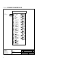
The focus has: 8 Analog Inputs for temperature sensors; 4 digital inputs
for remote overrides and plant fault; 4 black pushbuttons for local
extensions and overrides; 1 alarm / event review pushbutton; 6 digital
outputs for control of heating and hot water services; 2 analog outputs for
optional control of a boiler sequencer and a mixing valve.
For systems requiring greater input/output capacity than that provided by
the focus, the MF820 from Ambiflex offers a fully expandable system.
2
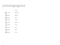
focus CONNECTION DETAILS
focus Address - 1
1
24 V AC
Power Supply
L
2 N
35
AI 1
240V AC
Supply
36
3 E
37
4 L
5 N
6 E
38
AI 2
Auxiliary
Supply
39
40
6A screen
7
8
DO
1
11
43
44
DO
2
45
46
47
AI 5
11A
12
42
AI 4
9
10
41
AI 3
DO
3
48
49
13
14
15
DO
4
AI 6
DO
5
AI 7
50
51
52
16
17
18
19
20
53
54
DO
6
55
56
AI 8
57
21 Voltage Enable
58
22
23
DI 1
24
AO
1
59
60
25
26
DI 2
27
61
AO
2
62
63
28 Voltage Enable
64
29
30
DI 3
31
32
33
DI 4
34
Ambiflex Ltd
5 Vale View
Vicarage Lane
Bowdon, Cheshire
WA14 3BD
Tel : 0161 941 1122
Fax : 0161 941 1188
3
Project
Rev
Description
Date
Customer
focus
Sheet No 1 of 1
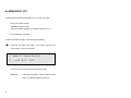
focus FEATURES
3 Time Channels for heating, an independent time channel and hot water.
fixed start/stop time
optimum start/stop time - heating
each day of the week independently programmable
Weather compensation available through boiler control and valve control,
room influenced control if required. Sophisticated boiler control through
strategies including: pre-programmed minimum on/off/step time delays,
integrated demand, variable minimum off time, equalised run time.
Pump run on and pump/valve exercise.
Multiple stage frost protection, economy settings including high limits for
room and outside air temperature.
4 Logs
one energy log with degree days.
two temperature logs, 8 temperatures/calculated temperatures
plus time/date
one optimised start/stop log
Event (alarm) recording, including optional plant fault and sensor faults.
Automatic BST/GMT changeover.
Capable of communications to a remote P.C. and networking.
4
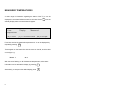
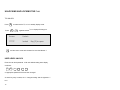
STANDBY DISPLAY
With the focus in its normal ‘locked’ mode, the display reverts to standby
mode whenever the ‘escape’ key is pressed )
or approximately 20
minutes after the last keystroke by the user. The following information is
shown in the standby mode.
Machine Type
Time, Date & Day
)focus HT620)
[0] = Info
10:14 15/07/02 Monday
[#0] = Adjust
[1}..{3] = Override
Quick Keys
Machine Type
Machine type and revision number.
Time, Date, Day
Time is in 24 hour format.
The date is always displayed in the
Day/Month/Year format.
Quick Keys
The keys to press (shown in brackets) which will
take the user directly to that part of the program.
5
USER FACILITIES
In addition to the standby display three additional facilities are available to
the focus User in the locked mode. These are:
Display
Where temperature values and system status
conditions may be displayed.
User Adjusts
Where preprogrammed controlled temperature
adjustments may be made.
Override Actions
Where pre-programmed override actions may be
selectively implemented.
These are carried out by pressing any of the four
black user override buttons:
cdef
Or by pressing the Quick Keys 1, 2 or 3 from the
Standby Display.
Words describing the specific override function will
appear in the display window.
6
STATUS DISPLAY MODE
With the focus locked
0 takes the user into User Display mode.
The user can go directly to any of the status display pages from the
standby display, in the locked mode by pressing0
which goes to the
first page, i.e.
7
:
Measured temperatures
Time channel info.
5
goes to
:
5
again to :
What is happening now?
5
again to
:
5
again to :
Measured temperatures
Any problems?
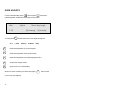
MEASURED TEMPERATURES
A wider range of information regarding the status of the focus can be
displayed in more detail whilst the machine is locked. Press
0
from the
standby display and the screen below will appear.
User
temperatures
[#] = view
Display
Measured
[5] = Channel status [)] = escape
From here each of the measured temperatures in °C can be displayed by
repeatedly pressing
#
These appear on the bottom line with the name on the left, and the value
on the right, e.g.:
Room 1
21.3
With the cursor flashing on ‘M’ of Measured temperatures, other status
information can be selected for display by pressing
5
Alternatively, to escape to the default display press
)
8
TIME CHANNEL INFORMATION
Key
5 and the display will change to:
User
[#] = view
Display
Time channel info
[)] = escape
[5] = Current status
From here information concerning each of the time channels can be
displayed by repeatedly pressing
#
These appear on the display and tell the user which time channel it is,
whether it is on or off and whether it is in an occupancy period. Eg:
Heating
On
Occupancy
[#]=nxtChn
With the cursor flashing on ‘T’ of Time channel info., other status
information can be selected for display by pressing 5 . Alternatively, to
escape to the default display press ) .
9
WHAT IS HAPPENING NOW?
5
The display will change to:
User
now?
[#] = view
Display
What is happening
[5] = Fault reports [)] = escape
From here the user can see anything which may be affecting the normal
control status by repeatedly pressing
# .
These appear on the bottom line e.g:
Heating OFF hi room
If there is nothing happening the display reads ‘no news’.
With the cursor flashing on ‘W’ of What is happening now?, other status
information can be selected for display by pressing 5 . Alternatively, to
escape to the default display press
10
).
ANY PROBLEMS?
5
The display will change to:
User
[#] = view
Display
Any problems?
[5] = Temperatures [)] = escape
From here the user can see whether there are any problems that should
be reported by repeatedly pressing # .
These appear on the bottom line e.g.:
Room 1 sensor FAULT
If there is nothing within this menu the display reads ‘no probs’.
With the cursor flashing on ‘A’ of Any problems?, other status information
can be selected for display by pressing 5 .
the default display press ) .
11
Alternatively, to escape to
USER ADJUSTS
From the default display press
# hold and press 0 . These keys
pressed together will take the user directly to this screen.
User
Adjust
21.0
Room day target
[9]=change
{5}=nxtAdj
To change this 9 and the bottom line of the display changes to:
21.0
2
5
[ 2=Up
5=Down
0=Reset
#ok ]
takes the temperature up by half a degree.
takes the temperature down by half degree.
0
takes the temperature to the default programmed in.
#
accepts the changes made.
#
again to return to normal display.
When the cursor is flashing over Room day target,
cursor to the next setpoint.
12
5
will move the
OVERRIDE ACTIONS – DEDICATED
PUSHBUTTONS
These override actions are accessed via black pushbuttons. The four
pushbuttons are normally used for:
Heating day extension
PB Switch c
Hot water day extension
PB Switch d
Summer mode
PB Switch e
Holiday mode
PB Switch f
The name of the programmed override function will be shown in the top
left hand side of the display screen.
Assuming the four buttons have been programmed as printed, they will
work as follows; at any time when the focus is locked ( ) does not need
to be pushed first).
c
The display will show:
override name
Extend heating by
exb 00:30 now/No
current override status
13
user action required
Switch 1 to action
Where ‘Switch 1 to action’ means press pushbutton c to increment day
heating extension times by 30 min.
When c is pressed once, ‘now No’ will change to ‘now Yes’
and ‘Switch 1 to action’ changes to ‘Switch 1 steptime’
c again and ‘+00:30’ changes to ‘+01:00’
c again and ‘+01:00’ changes to ‘+01:30’
Once the extension has been programmed the green LED will come on,
this will then start to flash when the timer has started to ‘run back’ at the
end of normal occupancy.
Repeatedly
pressing c
increases the extension time until the
preprogrammed limit is reached and with the next press, the display
changes to ’00:30 now No’ and the LED stops flashing, i.e. the override
action has been cancelled.
Alternatively, the override action can be cancelled at any time by holding
c down for a minimum of 3 seconds.
The maximum extension time available is four and a half hours and the
timer is programmed to time out after the end of the current time channel
ON time.
d
Is normally used to extend the Hot Water On time and the
operation is identical to c.
14
e
The display will normally show:
Summer - heating OFF
Switch 3 to action
now NO
e
Again and ‘nowNO’ changes to ‘nowYES’ and the green light
alongside flashes. All heating will be switched off but not hot
water.
e
Again will cancel the summer condition and the display bottom
line will change to ‘nowNO’.
f
Is normally used as a Holiday – all OFF switch and the operation
is identical to
N.B.
e.
During summer and holiday shutdown frost protection remains
active. Also the other pushbutton switches will remain functional; i.e. it is
possible to bring the heating and/or hot water on for whatever extension
time has been set at the same time.
15
OVERRIDE ACTIONS – KEYPAD
Holiday Shutdown
From the standby display press key
User
Action
(#=Yes
9=date)
1 . The following display appears:
Shutdown til dd/mm
end26/11
now NO
Follow the instructions on the screen: if the default date is required simply
press
# to accept, if a different end date is required key
to change
9
the date which is entered in a DD/MM format.
Press
# to accept. To cancel the override press #
Heating Off
From the standby display press key
2 . This override works identically
to the one described above except the hot water will continue to work on
its usual times.
Maintenance Override
Key
3 for emergency maintenance use – when activated the controller
is
will force everything on for a maximum of thirty minutes as a default
setting.
16
ALARMS/EVENT LIST
If critical alarms are being monitored by the focus they may either:
Bring on the alarm red light
Operate the inbuilt sounder
Send out an alarm message via a modem built into the focus
or any combination of all three.
To silence the alarm sounder, or stop the red light flashing:
Α
Press the red alarm push button.
The display will show the
current alarm or event, for example:
1] Node # 35 General Plant fault
A _ on @ 09:12
16/03
A maximum of 24 alarms/events can be stored on the list.
Node # nn
is the internal condition number assigned to that
alarm, for Ambiflex engineering use only.
17
If the alarm condition had cleared, the bottom line would read:
A _ on @ 11:15 21/07 clr @ 14:10 23/07
Where clr @ hh:mm dd/mm indicates the time and date at which the
alarm condition cleared.
Repeat Α and the display will step through the alarm list until the last
event has been displayed and the screen will show:
Alarm review
− No more incidents
Press [Alarm] to accept
You must now
Α
again to accept and return to the default display.
Once accepted the sounder will mute and the red flashing light will
become steady. The red light itself will not disappear until the alarm has
not only been reviewed but has also cleared.
18
UNLOCKING AND LOCKING THE focus
TO UNLOCK
Press
Press
9
to make sure the focus is in standby display mode.
)
# +
together and the focus display will change to:
)
Access
Unlock
??????
locked
Key [9] to open
and the cursor moves to the bottom line over the leftmost ‘?’
USER LEVEL UNLOCK
Enter the user level password. If left at its default setting enter display
as follows:
1
2
1
2
1
2
or appropriate password if this has been changed.
As each key entry is made, the ‘?’ changes starting with the rightmost ‘?’
to #.
19
# +
When all six digits have been entered:
0 twice to accept.
If entered correctly, the display will change to:
)
Access
Unlock
??????
open, user
to return to standby display, or key
1 then
5 to get to Time
Scheduling.
LOCKING THE focus
The focus will lock itself automatically 20 minutes after the last keystroke.
To lock it before this from the standby display:
#
)
20
+
)
then
3
9
to revert to standby display.
5
then
#+
0
FURTHER USER INFORMATION
When the controller has been unlocked to the User level there is more
information available in the User Display menu. From the standby display
key 0 to reach User Display Measured temperatures, from there use the
down cursor key 5 to see the options available. After the
‘Any problems?’ menu there are two new menus: ‘Info for engineers.’ and
‘Accumulator values’.
User
[#] = view
Display
Info for engineers.
[5] = Accumulators [)] = escape
From here the user can see whether there is any information for engineers
by repeatedly pressing
. These#appear on the bottom line.
If there is nothing within this menu the display reads ‘no info’.
The ‘Accumulator values’ menu can be reached by pressing key
5 from
the ‘Info for engineers.’ menu. This menu shows the accumulated run
hours for each boiler and pump.
There is also another menu available, this is ‘Optimes’ and can be found
0 from the standby display to reach the ‘Measured
temperatures’ menu, keying 1 to move the cursor to Display and then
by pressing
keying
5 twice. This menu shows a log of when the controller optimised
the heating on and off.
21
TIME SCHEDULING
For most day to day operations it is not necessary to make changes to the
Time Schedule settings. This is because override facilities are provided
by the 4 black pushbuttons.
For details of what override facilities have been provided for use when the
focus is ‘locked’ see Page 13-16 of this Guide.
If however, it is necessary to modify time switching commands
programmed at the commissioning stage, this can be done by the user,
but first the focus has to be unlocked by entering a password.
This
procedure was explained earlier (see Page 19-20).
USER LEVEL
At this level the user is allowed access to:
1.
Change any existing switching times for days already programmed.
It does not allow the user to:
a.
Add new switching times.
b.
Delete existing time switching commands.
Please ask your service engineer about adding and deleting time
commands.
22
MAKING TIME TABLE CHANGES
From USER Level Access
Reviewing Existing Time Tables
Unlock focus as explained in ‘focus Lock/Unlock’. The time table menu is
one below the Access menu. Therefore with the cursor flashing over the A
for Access key
and5 the TimeTabl menu will be reached. Alternatively,
from the standby display position press
+
2 and the
# together
display changes to:
TimeTabl Review
Heating
chnl 1
Any day
[#] = view [5] = nxt chn
# View the time table for channel 1 on for every day of the week e.g.
TimeTabl
Chn 1
23
[time ch: Channel 1
Opsrt
12345 . .
]
08:30
A cursor appears on the bottom line and this can be moved by using the
cursor keys on the keypad,
3
2 is up,
5 is down,
1
is left and
is right. As the cursor is moved an expanded description appears
on the top line. For example, if the cursor is under the command section
Opsrt, the upper line will read:
TimeTabl [command: Optimised START ]
Where a dot ‘.’ appears it means that the same command is set for the
same time for the day where the dot is positioned, i.e. a dot in position 3
would mean the same command is set for Wednesday. A dash ‘_’ means
the command is not set for that day.
Repeat pressing
#
to view all command lines for channel 1.
Then 5 to move the cursor from Chnl 1 to Chnl 2 to view other existing
time channels.
The focus has three channels, i.e. Heating, an Independent Channel and
Hot Water but the number used will vary for different applications.
24
To change the day on which the time schedule is viewed move the cursor
from Chnl 1 to Anyday by pressing 3 . Then
5
i.e:
Any Day
25
5
Goes to:
Week Days
5
Goes to:
Weekend
5
Goes to:
Mon (1)
5
Goes to:
Tues (2)
5
Goes to:
Wed (3)
5
Goes to:
Thu (4)
5
Goes to:
Fri (5)
5
Goes to:
Sat (6)
5
Goes to:
Sun (7)
to change this value
Changing Existing Switching Times
Once the required Time Channel has been selected, carry out the review
procedure for that channel for ‘Any day’ by pressing
# until the line to be
changed appears on the bottom line of the display, move the cursor over
the time by pressing key
9
then:
3
And the cursor will move to the left hand digit of the time currently
set.
h
e.g.
h
0
m
7
m
4
to enter the new switching time.
5
would set a time of 07:45 (24 hour format).
Once the correct time has been set, it can be entered into the system by
#
+
0 once. Then
# to move to the next command line.
To make changes to other time channels, select the required channel by
scrolling (
26
5 or
2 ) whilst the cursor is on the top line next to ‘chnl’.
CALENDAR SCHEDULING - DIARY
At USER level access, existing dates for suspending and restoring daily
time schedules may be changed.
CHANGING EXISTING DIARY DATES
As a standard convention, all
focus controllers are set where:
Holiday makes all channels inactive i.e. suspend all daily time
programmes starting on this date i.e. the first day of holiday
and the final date of the holiday i.e. normal operation
resumes the day after.
Return to the standby display by pressing ) . Then by pressing:
#
+
3
the display will show typically:
Diary Review
[#]=view
27
[5]=D.Logs
After reviewing existing dates, review again until the first date to be
changed is displayed then:
9
then select event required ie. Holiday
# +
0
to accept. Then key in the start date, this is in
Date/Month/Year format. If only the Date and Month are
entered then this event will occur every year, otherwise if
a specific year is entered, the event will be deleted once it
has occurred.
#
0
+
to accept. Then key in the date for the last day of holiday
operation.
E.g
A holiday like Christmas Day and Boxing Day
occurring every year could be entered as:
Holiday cal: all OFF 25/12/xx to 26/12
#
+
#
0
to accept.
to move to the next event to be edited.
Carry on until all dates have been reviewed, changed and
accepted.
N.B.
CALENDAR
DATES
IN
THE
DAIRY
CAN
ROLL
ON
CONTINOUSLY OR BE YEAR SPECIFIC.
Inserting and deleting calendar dates can only be done at Service and
Installer levels of access, please see those guides for further information.
28
TIME (CLOCKTIME) SETTING
The focus controller is battery backed and will retain its settings even if
power is lost.
Clock Adjustment
Changing clock times can be done at the USER Level of access (see
Pages 19 and 20 for unlock instructions) in the Timekeep Clockset Menu.
This menu can be reached by pressing
# and
7 together from the
default display.
9
and the cursor moves to the time at the bottom left hand side of
the display.
h
h
d
d
#
m
m
+
to enter correct time, then
m
0
m
y
y
0
to enter date including year.
and then the clock will update the ‘Day’ and ‘BST’
automatically.
29
# +
BRITISH SUMMER TIME (BST)
The default for the BST start date is set with the month only, e.g. 00/03 for
March the focus will change from Winter to Summer Time automatically at
02:00 on the last Sunday in March, every year. The GMT start date is
also set with the month only, e.g. 00/10
Occasionally this will be wrong for a period of 1 week only in some years
when the time change takes place on the Sunday before the last Sunday
in the month.
Specific dates can be entered into the controller if required from Service
level access and above.
For further information please see the Service Manual and Installation
Manual otherwise please contact us (contact details are on the back cover
of this manual).
30
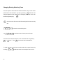
Focus Menu Map
User
Action
Shutdown til dd/mm etc.
Display
Measured temperatures
Time channel info.
What is happening now?
Any problems?
Info for engineers.
Accumulator Values
Adjust
Room day target etc
OpTimes
Access
Lock
Unlock
TimeTabl
Review
Heating
DLinkStat
CalSched
Review
Status
Datalogs
View
Timekeep
Clockset
#1 Daily etc
The above is for free access and
USER level access.
31
Anyday
USER NOTES
32