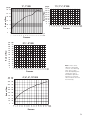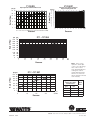
1
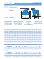
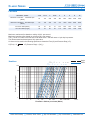
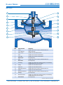
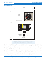
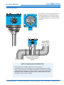
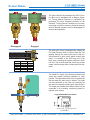
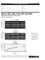
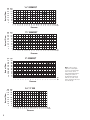
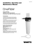
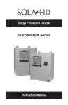
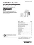
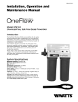
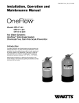
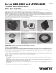
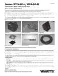
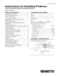
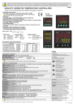
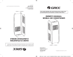
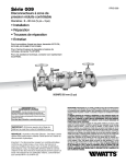
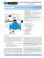
FLOOD PROTECTION SHUT DOWN VALVE
(3” and smaller)
01/10
F113-12RFP (Globe)
F1113-12RFP (Angle)
To lassic
Atmosphere Series
C
3
4
To Floor
Drain
JB113
L
6
5
FS99
X
2
X
• Installed upstream of Reduced Pressure Zone
Backflow Preventer.
• Normally Open Valve - Closes when discharge from
RPZ Relief Valve is sensed or by engaging Solenoid
Manual Operator.
• Limit Switch provides local visual and remote
electrical indication of valve closure.
• Valve must be manually reset. Pressure gauge
(provided) indicates valve reset for automatic service
• Anti-Scale Coated Main Valve Stem for added
protection.
• Fail Safe operation - Valve closes upon Main Valve
or Pilot Diaphragm failure.
Standard Components
X
FC
1
FLOW
CLOSES VALVE
OPENS VALVE
1 - Main Valve (Single Chamber)
2 - 3-Way Solenoid
3 - Manual Reset Ball Valve
Port 1 - Valve Cover
Port 2 - Pressure
Port 3 - Atmosphere
4 - JB113 Junction Box
5 - FS99 Flow Sensor
6 - Pressure Gauge
L - Limit Switch
X - Isolation Cocks
FC - Flo-Clean Strainer
Operations
The Watts Flood Protection Shutdown Valve system
prevents catastrophic property damage that can occur due to Relief Valve discharge and/or a blocked or
overwhelmed floor drain during normal relief valve operation. Typical conditions which can cause continuous
relief valve discharge are:
•
•
•
•
Fouled First Check Seat due to dirt, debris or rocks
Failed First Check Spring
Clogged or blocked Relief Valve Sensing Line
Relief Valve Diaphragm failure
The Watts 113-12RFP Flood Protection Shutdown
Valve is a normally open valve designed to be installed
upstream of a Reduced Pressure Zone (RPZ) Backflow
Prevention device. It is normally open and closes driptight when continuous relief valve discharge through the
drain pipe is sensed by the FS99 Flow Sensor, energiz12541 Gulf Freeway
ing the Solenoid Pilot. The Solenoid Pilot is equipped
with a Manual Operator which simulates power when
manually engaged. The valve mounted JB113 Junction
Box is equipped with an adjustable time delay to avoid
valve closure due to intermittent or nuisance relief valve
discharge. The Limit Switch provides local visual and
remote electrical indication of valve closure. The valve
remains closed and cannot re-open if flow stops or electrical service is interrupted, and must be manually reset
after the RPZ is diagnosed and/or repaired.
The valve comes complete with the valve mounted JB113
Junction Box with adjustable time delay, pre-wired Solenoid Valve, Manual Reset with Pressure Gauge, Limit
Switch and FS99 Flow Sensor (field installed). Fail-safe
operation is assured by closing valve upon Main Valve
or Pilot Diaphragm failure and a specially coated Main
Valve Stem for added protection.
• Houston, Texas 77034 • (Ph) 713.943.0688 • (Fx) 713.944.9445 • www.watts.com
F113-12RFP (Globe)
F1113-12RFP (Angle)
Classic Series
Globe
Materials
Angle
Body & Cover: Ductile Iron ASTM A536
L
Coating: NSF Listed Fusion
Bonded Epoxy Lined
and Coated
M
Trim: 316 Stainless Steel
D
K
Elastomers: Buna-N (standard)
EPDM (optional)
Viton (optional)
Stem, Nut & Spring:
Stainless Steel
H
A
E
B
C
F
G
I
J
Operating Pressure
Operating Temperature
Pilot System
Tubing & Fittings
Threaded = 400 psi
150 Flanged = 250 psi
300 Flanged = 400 psi
Buna-N: 160°F Maximum
EPDM: 300°F Maximum
Viton: 250°F Maximum
Solenoid
Brass
NEMA 4 General Purpose
110-VAC
Copper / Brass (Standard)
Stainless Steel (Optional)
Dimensions
A
B
C
D
E
F
G
H
I
J
K
VALVE GLOBE GLOBE GLOBE COVER TO ANGLE ANGLE ANGLE ANGLE ANGLE ANGLE PORT
SIZE THRD. 150#
300#
CENTER THRD.
150#
300#
THRD. 150#
300#
SIZE
1-1/4
7-1/4
-
-
3-1/2
3-1/4
1-1/2
7-1/4
8-1/2
2
9-3/8
9-3/8
2-1/2
11
11
11-5/8
3
10-1/2
12
4
-
15
-
9
3-1/2
3-1/4
10
4-15/16
4
7
5-1/2
5-1/2
13-1/4
7
5-1/4
15-5/8
8-5/8
-
-
-
L
M
PORT
SIZE
PORT
SIZE
SHIPPING
WEIGHTS*
1/2
1/8
15
-
1-7/8
1/4
4
-
1-7/8
4
-
1/4
1/2
1/8
15
4
4-1/4
4
4
4-1/4
1/2
1/2
1/4
35
5-13/16
4
4
4-5/16
1/2
1/2
3/8
65
5-3/4
6-1/8
5-1/4
5-3/4
6-1/8
1/2
1/2
3/8
95
6-3/4
7-1/8
-
6-3/4
7-1/8
1/2
1/2
3/8
190
6
-
20
21
11-3/4
-
8-1/2
8-7/8
-
8-1/2
8-7/8
1/2
1/2
1/2
320
8
-
25-3/8
26-3/8
15-3/4
-
11
11-1/2
-
11
11-1/2
1/2
1
1/2
650
10
-
29-3/4
31-1/8
18-3/4
-
14-7/8
15-5/8
-
14-7/8
15-5/8
1
1
1
940
For larger sizes consult factory
Valve Cover Chamber Capacity
Valve Size (in)
1-1/4
1-1/2
2
2-1/2
3
4
6
8
10
fl.oz.
4
4
4
10
10
22
70
-
-
U.S. Gal
-
-
-
-
-
-
-
1-1/4
2-1/2
Valve Size (in)
1-1/4
1-1/2
2
2-1/2
3
4
6
8
10
Travel (in)
3/8
3/8
1/2
5/8
3/4
1
1-1/2
2
2-1/2
Valve Travel
12541 Gulf Freeway
• Houston, Texas 77034 • (Ph) 713.943.0688 • (Fx) 713.944.9445 • www.watts.com
F113-12RFP (Globe)
F1113-12RFP (Angle)
Classic Series
Flow Data
Valve Size - Inches
1-1/4
1-1/2
2
2-1/2
3
4
6
8
10
Maximum Continuous Flow Rate Gpm
(Water)
93
125
208
300
460
800
1800
3100
4900
Maximum Intermittent Flow Rate Gpm
(Water)
115
158
260
370
570
1000
2300
3900
6000
CV Factor GPM (Globe)
29
34
55
75
125
220
460
775
1200
CV Factor GPM (Angle)
39
53
66
99
170
280
650
1100
1600
Maximum continuous flow based on velocity of 20 ft. per second.
Maximum intermittent flow based on velocity of 25 ft. per second.
The Cv Factor of a value is the flow rate in US GPM at 60° F that will cause a 1 psi drop in pressure.
The factors stated are based upon a fully open valve.
Cv factor can be used in the following equations to determine Flow (Q) and Pressure Drop (∆ P):
Angle
Globe
10
10 8
4
6
8
100
6
1 1/4
1 1/2
2 1 1/4
1 1/2
2 1/2 2
2 1/2
3
Headloss
3
∆ P (Pressure Drop) = (Q/CV)2
4
Q (Flow) = Cv ∆ P
Pressure Difference psi
50
10
5
1
1
5
10
50
100
500
1000
5000 10000 20000
100000
Flow Rate - Gallons per minute (Water)
12541 Gulf Freeway
• Houston, Texas 77034 • (Ph) 713.943.0688 • (Fx) 713.944.9445 • www.watts.com
F113-12RFP (Globe)
F1113-12RFP (Angle)
Classic Series
Main Valve
1
10
2
11
3
12
4
13
5
14
6
7
15
8
16
9
17
ITEM
DESCRIPTION
MATERIAL
1
Cover
ASTM A536 65-45-12 Epoxy Coated Ductile Iron
2
Cover Bearing
SAE 841 Bronze
3
Shaft / Stem
ASTM A276 304 Stainless Steel
4
Stud
ASTM A570 Gr.33 Zinc Plated Steel
5
Cover Nut
ASTM A570 Gr.33 Zinc Plated Steel
6
Diaphragm*
Buna-N (Nitrile)
7
Body
ASTM A536 65-45-12 Epoxy Coated Ductile Iron
8
Quad Seal*
Buna-N (Nitrile)
9
Seat Ring
ASTM A743 CF8M (316) Stainless Steel (8” and Smaller)
ASTM B62 Bronze (10” and Larger)
10
Spring
ASTM A276 302 Stainless Steel
11
Stem Nut
ASTM A276 304 Stainless Steel
12
Diaphragm Washer
ASTM A536 65-45-12 Epoxy Coated Ductile Iron
13
Spacer
ASTM A276 304 Stainless Steel
14
Quad Seal Retainer
ASTM A536 65-45-12 Epoxy Coated Ductile Iron
15
O-Ring*
Buna-N (Nitrile)
16
Quad Seal Plate
ASTM A743 CF8M (316) Stainless Steel (8” and Smaller)
ASTM B62 Bronze (10” and Larger)
17
Seat Gasket*
Buna-N (Nitrile)
* Contained in Main Valve Repair Kit
12541 Gulf Freeway
• Houston, Texas 77034 • (Ph) 713.943.0688 • (Fx) 713.944.9445 • www.watts.com
F113-12RFP (Globe)
F1113-12RFP (Angle)
Classic Series
JB113 Junction Box
6.00
Power
UP
15
Relay with
Red LED
Indicator
10
20
5
25
0
SEC
30
8.00
LNG 1 2 3 4 5 6
Incoming Power
120V, 1 PH
(Field Terminated)
Solenoid
( by factory)
FS-99
Flow Sensor
(Field Terminated)
3/4 “ Conduit Connections (x 3)
CERTIFIED ELECTRICIAN TO CONNECT MAIN POWER
AND FS99 FLOW SENSOR TO JB113 JUNCTION BOX
The valve mounted JB113 Junction Box is a lockable NEMA 4 enclosure equipped with an adjustable time delay,
electrical relay and terminal strip. There are three 3/4 inch conduit connections. The valve solenoid is prewired.
The valve is normally open and closes drip-tight when continuous relief valve discharge through the drain pipe is
sensed by the FS99 Flow Sensor.
The valve mounted JB113 Junction Box is equipped with an adjustable time delay to avoid valve closure due to
intermittent or nuisance relief valve discharge. The time delay is adjusable from 0-30 seconds.
Adjusting the dial clockwise increases the time delay for valve closure. Adjusting the dial counterclockwise decreases the time delay for valve closure.
12541 Gulf Freeway
• Houston, Texas 77034 • (Ph) 713.943.0688 • (Fx) 713.944.9445 • www.watts.com
F113-12RFP (Globe)
F1113-12RFP (Angle)
Classic Series
FS-99 Flow Sensor
The FS99 Flow Sensor is field installed in the
discharge piping from the RPZ Relief Valve.
The FS99 senses water in the discharge piping signaling the JB113 Junction Box to close
the valve.
From RPZ
Relief Valve
(with Air Gap)
To Floor Drain
Sensor Probes installed
1/4 inch above pipe
bottom
NOTE TO INSTALLING CONTRACTOR
•
•
•
•
•
Client/Contractor to provide installation Tee for Flow Sensor.
Install Flow Sensor in RPZ discharge line in HORIZONTAL position as shown.
Sensor Probes should be cut to length and installed 1/4 inch above pipe bottom.
ENSURE SENSOR PROBES DO NOT CONTACT PIPE BOTTOM OR SIDES.
CERTIFIED ELECTRICIAN TO CONNECT MAIN POWER AND FS99 FLOW
SENSOR TO JB113 JUNCTION BOX
12541 Gulf Freeway
• Houston, Texas 77034 • (Ph) 713.943.0688 • (Fx) 713.944.9445 • www.watts.com
F113-12RFP (Globe)
F1113-12RFP (Angle)
Classic Series
The valve Solenoid is prewired to the JB113 Junction Box and is equipped with a Manual Operator. Turning Manual Operator in (clockwise) approximatly 5-6 turns simulates electricity to the
Solenoid. Turning Manual Operator out (counterclockwise) returns the valve to electrical stand-by
service. Manual operator must be disengaged for
normal valve operation.
B
Engaged
Disengaged
A
A
A
B
A
Male Pipe
Thread (in)
1/4
3/8
1/2
A
Male Pipe
Thread (in)
1/4
3/8
1/2
B
C
Female Pipe
Length
Thread (in) Thread (in)
1/8
11/16
1/4
7/8
3/8
7/8
B
C
Female Pipe
Length
Thread (in) Thread (in)
1/8
11/16
1/4
7/8
3/8
7/8
The valve pilot circuit is equipped with a Model 60
Flo-Clean Strainer which is used to filter the fluid
passing through the control pilot circuit, and provide protection to pilot circuit speed controls and
pilots. It is installed in the inlet body port of the
main valve, exposing the strainer element to main
line flow. The currents and flow across the screen
create a self-scouring effect, cleaning the filter element.
The Model 51 Single Limit Switch provides local
visual and remote electrical indication of valve
position. The adjustable collar is set to contact the
trip arm when the main valve is closed. The collar
can be positioned on the stem by loosening the
set-screw to actuate the switch upon valve closure.
The single pole double throw Micro-Switch can be
connected to the building monitoring system to
indicate valve closure.
Single Pole Double Throw Switch
Normally Closed
Common Lug
Normally Open
12541 Gulf Freeway
• Houston, Texas 77034 • (Ph) 713.943.0688 • (Fx) 713.944.9445 • www.watts.com
F113-12RFP (Globe)
F1113-12RFP (Angle)
Classic Series
1
3
4
5
6
7
8
9
10
11
12
13
2
14
15
1
Limit Switch
9
Guide
2
Bracket
10
O-Ring*
3
Stem
11
Polypak*
4
Trip collar
12
Locknut
5
Set Screw
13
Body
6
Cap
14
Pin
7
Wiper Ring*
15
Coupling
8
O-Ring*
12541 Gulf Freeway
• Houston, Texas 77034 • (Ph) 713.943.0688 • (Fx) 713.944.9445 • www.watts.com
Classic Series
F113-12RFP (Globe)
F1113-12RFP (Angle)
Installation
Control Valve
•
•
•
•
•
•
•
•
•
Fully read all technical information provided.
Prior to installation flush line to remove debris.
Install valve upstream of the RPZ Backflow Assembly.
For ease of valve service and electrical connections do not install valve vertically. Install
valve horizontally “in line” (valve cover facing UP), so flow arrow matches flow through the
line. Consult factory prior to ordering if installation requirements are other than described.
Vertical installation of valves larger than 6” is not recommended and may result in poor valve
performance and increased maintenance requirements.
Install inlet and outlet isolation valves. NOTE: When using butterfly valves, insure disc does
not contact control valve. Damage or improper valve seating may occur.
Provide adequate clearance for valve servicing and maintenance.
Install pressure gauges to monitor valve inlet and outlet pressure.
Connect cover discharge control tubing to floor drain. Consult “Valve Cover Capacity” chart
on page 2 to determine volume of cover fluid displaced when valve is operated.
FS99 Flow Sensor
• Install FS99 Flow Sensor HORIZONTALLY in RPZ Relief Valve discharge line for proper
operation. Do not install vertically. Consult factory if flow sensor other than FS99 is used.
• Client / Contractor to provide 2” FNPT installation Tee for Flow Sensor. Sensor Probes must
be field cut to length and installed 1/4” above pipe bottom for proper operation
• Insure sensor probes do not contact installation Tee bottom or sidewalls.
• Line Voltage to FS99 Flow Sensor is 10 volts maximum.
Electrical Connections
• Certified Electrician to connect JB113 Junction Box and FS99 Flow Sensor according to
factory schematic to appropriate power source and terminal strip locations.
• Line Voltage to FS99 Flow Sensor is 10 volts.
• Power supply to JB113 Junction Box is 120 VAC 60HZ Single Phase.
• Connect Limit Switch (if equipped) to remote alarm or auxiliary connection as required by
project specifications.
• Pre-set Time Delay to 15 seconds.
• Insure Solenoid is disengaged by turning Manual Operator counterclockwise (out / left).
12541 Gulf Freeway
• Houston, Texas 77034 • (Ph) 713.943.0688 • (Fx) 713.944.9445 • www.watts.com
Classic Series
F113-12RFP (Globe)
F1113-12RFP (Angle)
Start-Up
Proper Automatic Control Valve start‑up requires bringing the valve into service in a controlled manner.
All adjustments to control pilots and speed controls should be made slowly, allowing the valve to respond
and the system to stabilize. NOTE: Control Valves should be set‑up in a dynamic (flowing) condition
for proper start‑up. Provisions for flow must be made to insure proper settings.
1. Refer to valve schematic. Disengage Solenoid by turning Manual Operator counterclockwise (out).
Locate and open Manual Reset Ball Valve. Open upstream and downstream isolation valves to
allow controlled filling of the Valve and Backflow Assembly. Open all Isolation Ball Valves.
2. Inlet pressure will open the valve fully. Close Manual Reset Ball Valve.
3. Engage Solenoid by turning (red) Manual Operator clockwise (in) to simulate electrical shutdown
signal. Inlet pressure will be indicated on Pressure Gauge and valve will begin to close. Due to
low / no flow condition, valve closure may be slower than normal operation. When valve is fully
closed adjust Limit Switch trip arm and trip collar to actuate Limit Switch.
4. Disengage Solenoid by returning Manual Operator out (counterclockwise) and open Manual Reset
Ball Valve. Pilot System Pressure Gauge will drop to zero. Valve will open fully and is ready for
electrical activation. Allow for cover volume to discharge to floor drain. Refer to chart on Page 2
for Cover Chamber Volume. Close Manual Reset Ball Valve.
5. Open JB113 Junction Box. Apply power and observe the clear Electric Relay Control.
6. Pour adequate amount of water into RPZ Relief Valve Air Gap until the RED LED indicator light on
the Electrical Relay illuminates / flashes. This indicates the FS99 Flow Sensor is properly installed
and is sensing water in the discharge piping.
7. Trap water in discharge piping and observe RED LED on Electrical Relay. Solenoid will energize
when duration of Adjust Time Delay elapses. Valve will go closed and must be manually reset.
Adjust Time Delay to Customer / Project specifications. To manually reset valve refer to Step 4.
8. For final test simulate actual RPZ Relief Valve discharge and observe floor drain for excessive
pooling or flooding. Re-adjust time delay and valve speed controls as needed to achieve desired
valve closure time.
12541 Gulf Freeway
• Houston, Texas 77034 • (Ph) 713.943.0688 • (Fx) 713.944.9445 • www.watts.com
Classic Series
F113-12RFP (Globe)
F1113-12RFP (Angle)
Specifications
The Flood Protection Shutdown Valve shall be a normally open Diaphragm Valve installed upstream of the
Reduced Pressure Zone Backflow Assembly, and automatically close if the RPZ relief valve begins to discharge.
A Time Delay supplied in the JB113 Junction Box shall prevent the valve from closing on intermittent discharges
from the RPZ relief valve. If continuous Relief Valve discharge occurs, the FS99 Flow Sensor installed horizontally
in the RPZ Relief Valve discharge piping shall send a signal to the JB113 Junction Box energizing Solenoid to
close the main valve. Once closed the Flood Protection Shutdown Valve must be manually reset.
The JB113 Junction Box shall be valve mounted with the Solenoid pre-wired. The FS99 Flow Sensor shall
be provided with the valve package and shall be field installed in a horizontal position in the RPZ Relief Valve
discharge piping. Vertical installation of the Flow Sensor shall not be acceptable. The valve shall be equipped
with a Limit Switch to provide local visual and remote electrical indication of valve closure.
The Reduced Pressure Zone Backflow Assembly, Flood Protection Shutdown Valve, JB113 Junction Box and
FS99 Flow Sensor shall be provided by the same manufacturer and be covered by a single warranty policy.
The main valve shall be a hydraulically operated, single diaphragm actuated, globe or angle pattern valve.
Y-pattern valves shall not be permitted. The valve shall contain a disc and diaphragm assembly that forms a
sealed chamber below the valve cover, separating operating pressure from line pressure. The diaphragm shall
be constructed of nylon reinforced Buna-N, and shall not seal directly against the valve seat and shall be fully
supported by the valve body and cover. Rolling diaphragm construction will not be allowed and there shall be no
pistons operating the main valve or any pilot controls.
The main valve body and cover shall be Ductile Iron ASTM A536, and all internal cast components shall be
Ductile Iron or CF8M (316) Stainless Steel. All Ductile Iron components, including the body and cover, shall be
lined and coated with an NSF 61 Certified Epoxy Coating applied by the electrostatic heat fusion process. All
main valve throttling components (valve seat and disc guide) shall be Stainless Steel. The valve body and cover
must be machined with a 360-degree locating lip to assure proper alignment.
The disc and diaphragm assembly shall contain a Buna-N synthetic rubber “Quad Seal” that is securely retained on
3-1/2 sides by a disc retainer and disc guide. Diaphragm assemblies utilizing bolts or cap screws for component
retention will not be permitted. Direction of flow through the valve shall be the over-the-disc design, causing the
valve to close upon diaphragm failure.
The exposed portion of the Quad Seal shall contact the valve seat and seal drip-tight. The disc and diaphragm
assembly must be guided by two separate bearings, one installed in the valve cover and one concentrically
located within the valve seat, to avoid deflection and assure positive disc-to-seat contact. Center guided valves
will not be permitted. The main valve stem shall be Xylan coated to avoid the effects of mineral or hard water
build-up. The main valve spring shall be the manufacturer’s heavy or extra heavy spring design. All necessary
repairs shall be made from the top of the valve while the body remains in line.
The Pilot Control System shall contain a Flo-Clean Strainer, NEMA 4, 120 VAC 60HZ 3-Way Solenoid with Manual
Operator, Manual Reset Ball Valve, Pressure Gauge, Single Limit Switch, JB113 Junction Box and Isolation Ball
Valves on all body connections. The JB113 Junction Box shall be valve mounted and the FS99 Flow Sensor shall
be field installed.
The valve shall be Watts Model 113-12RFP (globe) or 1113-12RFP (angle) Flood Protection Shutdown Valve.
12541 Gulf Freeway
• Houston, Texas 77034 • (Ph) 713.943.0688 • (Fx) 713.944.9445 • www.watts.com
ES-RVD
For Health Hazard Applications
Job Name –––––––––––––––––––––––––––––––––––––––––––
Contractor ––––––––––––––––––––––––––––––––––––––––––––
Job Location –––––––––––––––––––––––––––––––––––––––––
Approval
Engineer –––––––––––––––––––––––––––––––––––––––––––––
Contractor’s P.O. No. –––––––––––––––––––––––––––––––––––
Approval –––––––––––––––––––––––––––––––––––––––––––––
Representative
–––––––––––––––––––––––––––––––––––––––––––––
––––––––––––––––––––––––––––––––––––––––
Series 009, 909, 919, 957 and 994
Reduced Pressure Zone Assemblies
Rate of Flow
Relief Valve Discharge Rates
lpm gpm
152 40
133 35
114 30
95 25
76 20
57 15
38 10
19
5
0
0
⁄ ", 3⁄8", 1⁄2" 009QT
14
0
0
10 20 30 40 50 60 70 80 90 100 110 120 130 140 150 160 170 180 psi
.7 1.4 2.0 2.8 3.5 4.1 4.8 5.5 6.2 6.9 7.6 8.3 9.0 9.7 10.3 11.0 11.7 12.4 bar
Rate of Flow
Pressure
lpm gpm
266 70
228 60
190 50
152 40
114 30
76 20
38 10
0 0
⁄ " 009M3QT
34
0
0
10 20 30 40 50 60 70 80 90 100 110 120 130 140 150 160 170 180 psi
.7 1.4 2.0 2.8 3.5 4.1 4.8 5.5 6.2 6.9 7.6 8.3 9.0 9.7 10.3 11.0 11.7 12.4 bar
Rate of Flow
Pressure
1" 009M2QT
lpm gpm
228 60
190
50
152
40
114
30
76
20
38
10
0
0
0
0
10
69
20
138
30
207
40
276
50
345
60
414
70
483
80
552
90
621
100 psi
690 kPa
Pressure
Watts product specifications in U.S. customary units and metric are approximate and are provided for reference only. For precise measurements,
please contact Watts Technical Service. Watts reserves the right to change or modify product design, construction, specifications, or materials without prior notice and without incurring any obligation to make such changes and modifications on Watts products previously or subsequently sold.
Note: These curves
represent catastrophic
or worst case discharge
rates. These curves
were developed by pressurizing the outlet of
the backflow preventer
with the second check
valve’s internals removed
from the body.
Rate of Flow
Rate of Flow
lpm gpm
532 140
456 120
380 100
304
80
228
60
152
40
76
20
0
0
lpm gpm
513
35
456 120
399 105
342
90
285
75
228
60
171
45
114
30
57
15
0
0
11⁄4" 009M2QT
0 10
0 .7
20 30 40 50 60 70 80 90 100 110 120 130 140 150 160 170 180 psi
1.4 2.1 2.8 3.5 4.1 4.8 5.5 6.2 6.9 7.6 8.3 9.0 9.7 10.3 11.0 11.7 12.4 bar
Pressure
11⁄2" 009M2QT
0 10
0 .7
20 30 40 50 60 70 80 90 100 110 120 130 140 150 160 170 180 psi
1.4 2.1 2.8 3.5 4.1 4.8 5.5 6.2 6.9 7.6 8.3 9.0 9.7 10.3 11.0 11.7 12.4 bar
Rate of Flow
Pressure
lpm gpm
836 220
760 200
684 180
608 160
532 140
456 120
380 100
304
80
228
60
152
40
76
20
0
0
2" 009M2QT
0
0
10 20
.7 1.4
30 40
2.1 2.8
50
3.5
60 70 80
4.1 4.8 5.5
90 100 110 120 130 140 150 160 170 psi
6.2 6.9 7.6 8.3 9.0 9.7 10.3 11.0 11.7 bar
Pressure
Rate of Flow
lpm gpm
1330 350
1140
300
950
250
760
200
570
150
380
100
190
0
50
0
21⁄2", 3" 009
0 10 20 30 40 50 60 70 80 90 100 110120 130 140 150 160 170 180 psi
0 .7 1.4 2.1 2.8 3.5 4.1 4.8 5.5 6.2 6.9 7.6 8. 3 9.0 9.6 10.3 11.0 11.7 12.4 bar
Pressure
2
Note: These curves
represent catastrophic
or worst case discharge
rates. These curves
were developed by pressurizing the outlet of
the backflow preventer
with the second check
valve’s internals removed
from the body.
⁄ ", 1" 909
34
lpm gpm
570 150
Rate of Flow
1330
1140
950
760
570
380
190
0
475 125
Rate of Flow
380 100
285
75
190
50
95
25
0
0
11⁄4", 11⁄2", 2" 909
lpm gpm
1520 400
350
300
250
200
150
100
50
0
0 10 20 30 40 50 60 70 80 90 100 110 120 130 140 150 160 170 180 psi
0 .7 1.4 2.1 2.8 3.5 4.1 4.8 5.5 6.2 6.9 7.6 8. 3 9.0 9.6 10.311.0 11.712.4 bar
Pressure
0 10 20 30 40 50 60 70 80 90 100 110 120 130 140 150 psi
0 .7 1.4 2.1 2.8 3.5 4.1 4.8 5.5 6.2 6.9 7.6 8. 3 9.0 9.6 10.3 bar
Rate of Flow
Pressure
lpm
2090
gpm
550
1900
500
1710
450
1520
400
1330
350
1140
300
950
250
760
200
570
150
380
100
190
50
0
0
21⁄2" - 3" 909
0 10 20 30 40 50 60 70 80 90 100 110 120 130 140 150 160 170 180 psi
0 .7 1.4 2.1 2.8 3.5 4.1 4.8 5.5 6.2 6.9 7.6 8. 3 9.0 9.6 10.3 11.0 11.7 12.4 bar
Rate of Flow
Pressure
lpm
3420
gpm
900
3040
800
2660
700
2280
600
1900
500
1520
400
1140
300
760
200
380
100
0
0
4", 6", 8", 10" 909
0 5
0 .3
15 25 35
1.0 1.7 2.4
45 55 65
3.1 3.8 4.5
Note: These curves
represent catastrophic
or worst case discharge
rates. These curves
were developed by pressurizing the outlet of
the backflow preventer
with the second check
valve’s internals removed
from the body.
75 85 95 105 115 125 135 145 psi
5.5 5.9 6.5 7.2 7.9 8.6 9.3 10 bar
Pressure
3
2" 919 QT
1" 919 RV
50
152
40
114
30
76
20
38
10
0
0
lpm gpm
684
Rate of Flow
Rate of Flow
lpm gpm
228 60
190
Backpressure w/Second Check
Poppet & Spring Removed
Capacity w/Second Check Removed
6.8
570
532
456
380
342
304
266
228
190
152
114
76
38
0
0 10 20 30 40 50 60 70 80 90 100 110120 130 140150 160 170 180 psi
0 .7 1.4 2.0 2.8 3.5 4.1 4.8 5.5 6.2 6.9 7.8 8.3 9.0 9.710.311.011.712.4 bar
180
170
160
150
140
130
120
110
100
90
80
70
60
50
40
30
20
10
0
0
0
10
.7
20 30
1.4 2.1
Rate of Flow
2660
700
700
2280
600
600
1900
500
1520
400
1140
760
380
0
300
200
200
100
100
00
70
4.8
80
5.5
90
6.2
100 110 psi
6.9 7.6 psi
500
400
300
00
0
4040
276
80
80
552
120
120
827
160
1103
160
200
200
1379
240
240
1655
280
280
1931
300
psi
kPa
Pressure
Note: These curves
represent catastrophic
or worst case discharge
rates. These curves
were developed by pressurizing the outlet of
the backflow preventer
with the second check
valve’s internals removed
from the body.
21⁄2" – 10" 957
lpm gpm
1330 350
1140 300
Rate of Flow
60
4.1
21⁄2" – 10" 994
lpm gpm
900
3420 900
800
800
50
3.5
Pressure
Pressure
3040
40
2.8
950 250
Typical Flow Rates as
sized by floor drain
manufacturers
760 200
570 150
380 100
gpm
Drain
Size
lpm
190
50
55
209
2
0
0
112
426
3
170
646
4
350
1330
5
0
0
20
138
40
276
Pressure
Wa t e r S a f e t y & F l o w C o n t ro l P ro d u c t s
ES-RVD 0904
60
414
80 psi
552 kPa
USA: 815 Chestnut St., No. Andover, MA 01845-6098; www.watts.com
Canada: 5435 North Service Rd., Burlington, ONT. L7L 5H7; www.wattscanada.ca
© Watts, 2009