1
“Ocean Spirit”
A 57' Symbol Motoryacht
Vessel Operating Manual & Notes
Edition of March 26, 2006
Copyrighted. See notice next page
Tab
Contents
1
Table of Contents & About this Manual
2
QUICKSTART & Daily Operating Procedure Checklist
3
Specifications, Capacities, & Important Numbers
4
General Description & Operating Suggestions
5
Specific Discussion of Boat Systems & Inventory
6
“What to Do If” for each Boat System Concern
7
EMERGENCY PROCEDURES!
8
Inventory
9
Index
10
“Maneuvering Inboard Engine Power Boats”
“Binder # 0"
(Intentionally left blank)
Section I: Table of Contents & About This Manual
Manual Objective and Limitations
This vessel Operating Manual and Owner’s Notes is intended to introduce you to “Ocean
Spirit” and its systems and features, allowing you to operate it with the confidence and selfassurance necessary to enjoy your cruising vacation to its fullest. It is not intended to replace a good
basic understanding of seamanship, including navigation skills, weather interpretation or boat
handling. You are expected to have an understanding of these subjects obtained through other
sources, including training, seminars, reading and perhaps most important, experience.
Please prepare for using the boat by studying this manual thoroughly before taking the helm!
Ocean Spirit is a very sophisticated vessel, and there is no way that a manual like this one can
answer every question or give you a solution to every circumstance, foreseen or unforeseen, so in
addition to this manual, you will need your experience and/or reference to the manufacturer’s
instructions for many of the vessel’s components, especially the electronics systems including
particularly the computer navigation system.
14 separate binders with detailed information about each specific piece of equipment that are
on the boat are referenced throughout this manual; you will see them listed on the next page.
If you have a question which limits your understanding or handling of this vessel, ask your
checkout skipper or contact the office for details (you might make a list of questions as you read the
manual, saving them all up to ask at one time).
How these Owner’s Notes are Organized
•
Tab/Section 2 contains a detailed “QUICKSTART GUIDE” and “Daily Operations Checklist”
will remind you of essential operations you need to do every time you operate the vessel. You
should have it available so that it can be used on a daily basis throughout your trip even after
you are familiar with the boat.
•
Tab/Section 3 is a quick reference to vessel specifications and registration numbers.
•
Tab/Section 4 (this section) has a general description of the boat and some general
operating/maneuvering/anchoring suggestions.
•
Tab/Section 5, which describes each vessel system, is organized with detailed footings on
each page to make it easy to look up any general subject, although references are in the Table
of Contents (tab 1) and the Index (tab 9)..
•
Tab/Section 6, “What to Do If...” helps you troubleshoot some common problems.
•
Tab/Section 7, is a quick reference to vital Emergency Procedures.
•
Tab/Section 8 is the Vessel Inventory prepared by the owner to help you find equipment.
•
Tab/Section 9 has a complete detailed Index in alphabetical order by subject.
Copyright 2005 Joseph D. Coons. These Owner’s Notes were written for this boat’s owner
by Joseph D. Coons, 25 Shorewood Drive, Bellingham, WA 98225, telephone (360) 647-0288. All
rights reserved. These Owner’s Notes may not be quoted, copied, or duplicated, in whole or in part,
in printed or electronic form, without express written consent from the author.
1.1 - Table of Contents, About this Manual
Table of Contents
Section/
Page
Description
1.3 Table of Contents of Ship’s Binders by
Binder
5.18 Heads & Holding Tanks
5.18 Vacu-Flush Heads
5.19 Head Problems, Y-Valves
5.19 Holding Tank Pumpout, Macerator Pumps
5.20 Diesel Furnace System
2.0 Quickstart & Daily Operations Checklist
3.0 Specifications,
Numbers
Capacities
&
Important
4.0 General Description of this Vessel
4.1
4.2
4.5
4.6
Exterior
Interior
Engine Room
Lazarette, Dinghy, Deck & Safety Equipment
4.7 Maneuvering & Operating Suggestions
4.7 Docking, Thrusters, Filling Tanks
4.8 Anchoring
4.9 Shore Lines
4.10 Picking up a Buoy & Trim Tabs
5.0 Specific Boat Systems
5.21 Cooking and Refrigeration Equpment
5.21 Stove, Microwave/Convection Oven
5.21 Refrigerators, Freezer & Icemaker
5.22 Barbecue, Dishwasher
5.22 Washer/Dryer, Disposal, Vacuum
5.23 Wesmar Stabilizers
5.24 Electronics
5.24 Autopilot
5.24 Cockpit TV Monitoring System
5.25 Depth & Speed Indicators, Digital Compass
5.26 GPS and Charting Systems
5.27 Hailer, Intercom, Radars
5.27 Stereos & TV’s, Satellite Radio, Ipod Input
5.27 TV Satellite Receiver
5.28 VHF Radios, Weather Monitor
5.29 Wind Indicator
5.30 Satellite Radio
5.1 Engines & Controls
5.3 Mathers MMC Engine Controls
5.3 Strainers & Seacocks
5.5 Fuel System, Tank Measurement
5.5 Fuel Transfer, Oil Change Pump
6.0 What to Do If...
Answers
typical
questions...
5.6 Dinghy and Davit
5.7 Outboard Motor
8.0 Vessel Inventory, Spare Parts & Locations
major
operating
7.0 EMERGENCY PROCEDURES
9.0 Index
5.8 Fresh & Salt Water Systems, Waste Water
5.10 Electrical Systems
5.10 Concepts
5.11 Battery Banks & Battery Water
5.12 The DC Electrical System, DC Power Panel
5.13 The DC Link 10 Energy Monitor
5.14 The AC Electrical System
5.14 Connecting/Disconnecting Shore Power
5.15 The AC Power Panel
5.16 The Inverter System
5.17 The Generator System/Problems
10. “Maneuvering Inboard Engine Power
Boats”
FOLLOWING TAB 10:
Tab 1: Ship’s Papers & Dinghy Papers
Tab 2: USCG Inspections & Boardings
Tab 3: Customs Clearance Log
Tab 4: Operating Log
Tab 5: Maintenance Log
1.2 - Table of Contents, About this Manual
Index to Separate Manual Volumes (In Binders on Vessel)
Binder
Summary of Contents
1
Vessel Operating Manual/Documents
(White Binder)
This Operating Manual
Ship’s papers
Boarding reports
Customs paperwork
Operating Log
2
“Symbol Owners Manual” (Black Binder)
Vessel Specifications
Wiring Diagrams
Piping & Seacock Drawings
Engine Room Bulkhead Layouts
Shaft Specifications
Equipment List & Suppliers
3
4
5
6
Vessel Sub-Systems (Black)
Webasto hot water heat
Vacu-Flush Sanitation System
Heart Inverter
True Charge & Pro Mariner Chargers
Glendinning Cablemaster
Step-Up Transformers& Zinc Saver
Groco Flo-Master Vane Pump
Appliances (Black)
Marvel/U-Line Refrigerators
GE Washer-Dryer / Frigidaire DW
Miele Stovetop / Jenn-Aire BBQ
Profile Microwave-Convection Oven
NuTone Central Vac / Water Heaters
Kohler/ Moen / Grohe Accessories
Power & Control Systems (Black)
Northern Lights Generator
Nobels Bow & Stern Thrusters
Mathers Controls / Hynautic Steering
Muir Anchor Windlass
Robertson A/P Pump
Propellor Records
Radar/Entertainment Systems #1 (Black)
Simrad Radars
Micrologic DGPS
Optimus Receiver
Optimus CD Changer
Bose Speakers
Binder
Summary of Contents
7
Entertainment Systems #2 (Black)
Panasonic PV-C920-K TV
Sylvania 3819LC Color TV
Technics AV Control Stereo Receiver
Toshiba DVD Video Player
Sony Clock Radios
KVH Tracvision G4 Sat Receiver
Sony Digital Satellite Receiver
8
Main Engines (Black)
Operating, Fluid, Parts, Service and
Warranty Manuals
Fireboy Fire System
9
Pilothouse Electronics (Black)
Robertson Autopilot
Simrad Echo Sounder
Micrologic DGPS
SEA VHF-Hailer
Davis Weather Station
IS11 Data System / ISI Wind
10
Flybridge Electronics (Black)
Shipmate VHF
Simrad Echo Sounder
KVH Digital Compass
Robertson Autopilot
Simrad IS11 Instrument System
11
Miscellaneous A (Black)
Wesmar Stabilizers
Pro-Sine Inverter
Link Digital Power Monitor
12
Computer Hardware & Software (Black)
Ocean PC Computer
Viewsonic Monitor
Digital Mouse
APC UPS System
13
Dinghy & Outboard (Black)
AB RIB Dinghy
Honda Outboard
14
Construction & Outfitting Records (Black)
1.3 - Table of Contents, About this Manual
(Intentionally Left Blank)
1.4 - Table of Contents, About this Manual
Section II: “Quickstart” &
Daily Operating Procedure Checklist
Upon Boarding Ocean Spirit before Use:
9
Power panel: All “Green Dot” breakers “On”, “Yellow Dot” items evaluated for use.
Blue Dot: 24 volt items;
9
Red Dots: Head discharge
Canvas removed as appropriate, stowed under flybridge L-settee.
First Thing Each Day:
9
Check engine oil, coolant in mains. Check Genset oil.
9
Check under-engine oil pads. Okay?
Q
Check fuel and water tank levels with tank fuel gauge system.
9
Check holding tank indicator. Need pumping or processing?.
9
Are all portholes closed and secure?
9
Turn off anchor light if illuminated.
Starting Engines:
9
Pilothouse instruments “On” and warmed up.
9
Ship’s computer on and navigation software running.
(1) “PC” switch “On” to right of helm;
(2) Display power button “On”.
(3) “X” out of MSN Welcome screen.
(4) Minimize Camera Image (if present) by clicking underline “ ” at right top.
(5) Double-click Nobeltec software Icon.
(6) After software loads, click green “Boat” logo.
9
All lines clear of propellers and on deck.
9
Items running on AC evaluated vis-a-vis the Inverters and Generator.
9
Throttles/Shifters in “neutral”; Turn a key one “click”, buzzer will sound
9
Push MMC “CTRL” on engine throttle/shifter; release button, red light will stay on
9
Use engine keys to start engines in turn, then idling (See MMC instructions!).
9
If engines do not turn over, see “What to Do If”
Leaving Dock: (Only 3-4 minute engine warmup required!]
9
Shore power switch to “Off”.
9
Shore power adapters removed, stowed on board, cable reeled in (Cablemaster).
9
Lines removed as appropriate.
(Continued on Next Page)
2.1 - "Quickstart" Checklist
“Quickstart” / Daily Operating Checklist Continued
Soon After Away from Dock:
9
Fenders hauled aboard and stowed.
9
Lines and other deck gear secure/stowed.
9
Doors and hatches closed and secured as appropriate.
Underway:
9
Helmsperson on watch at all times.
9
Stabilizers “On”, set to correct sensitivity (typically “5") and “Engaged”.
9
RPM under 1400 until engines warm to 140°; RPM never to exceed 2300 RPM.
9
Wake effects always in mind.
Approaching Dock:
9
Fenders out on appropriate side.
9
Bow line OUTSIDE stanchions and bloused around toward midships.
9
Stabilizers in “Standby” mode.
9
Engines dead slow, wheel centered for engine-only/thruster maneuvering.
9
Mate ready to secure stern first (in most circumstances).
9
Trim Tabs in fully “Bow Up” position! (Important!)
Upon Arrival at Dock in Marina:
9
9
9
9
9
9
Lines secure, including spring lines.
(Reminder) Trim Tabs fully “Bow Up”!
If using Shore Power:
— Hot Water Heater breaker off until Inverter current settles
— Other heavy AC loads also off until inverter current settles
Shore power cord connected, shore power switch “On” to appropriate power location.
Shore power confirmed on displays, then Inverter “On”.
Electric use monitored, limited to capacity of shore facilities and connections.
Arriving at Mooring Buoy:
9
9
9
Q
Q
Q
Q
Trim Tabs fully “Bow Up” (Important!)
Stabilizers in “Standby” mode.
Skipper puts starboard end of swim step, with mate on it, next to buoy.
Mate loops 30' or so of heavy line, such as bow line, through buoy ring.
Mate holds two ends together, walks up side of boat to bow of boat.
With buoy held close to bow, line secured to each bow cleat through hawsepipe.
Inverters “Off” unless in use as inverter or charger; generator running if required.
(Continued on Next Page)
2.2 - "Quickstart" Checklist
“Quickstart” / Daily Operating Checklist Continued
Mooring at Anchor:
9
9
9
Q
Q
Q
Trim Tabs fully “Bow Up”
(Important!).
Stabilizers in “Standby” mode.
Check under-engine oil pads. Okay?
Anchor is lowered from pulpit while boat is backed up slowly away from anchor.
When desired chain length out (4:1 or 5:1 scope), windlass is stopped.
Engines reversed for “count of five” until chain pulls up virtually straight. Note: The
boat is not held in reverse against a taught anchor chain!
Stopping Engines:
9
Use red “Stop Button” before turning key!
Generator Starting/Stopping:
Q
Q
Q
Q
Q
Hold “Preheat” switch for 15 seconds, then hold both “Preheat” and “Start” until starts.
Check stern exhaust outlet for water flow.
After one minute for warmup, turn power selector from “Off” to “Gen”.
Stopping: Turn power selector from “Gen” to “Off”, wait one minute for cool-down.
Hold “Stop” switch until stopped.
Overnight Checklist in Marina:
Q
Q
Shore power “On”.
Inverter “On”.
Overnight at Anchor or Buoy:
Q
Q
Q
Q
Run generator until batteries fully charged as shown on Link 10 Power Monitor
Inverter “Off” to conserve batteries unless in use as inverter or charger.
Anchor light “On”.
Unnecessary DC electrical items all “Off” including radios, extra lights, etc.
Upon Arising:
Q
Q
Q
Q
If at anchor or buoy, Inverter only “On” if necessary.
Start generator if necessary for battery charging.
Inverter “On” if shore power available or generator running.
Turn on heat if necessary. Go to top of this Ocean Spirit checklist.
After Use, and after “Arrival at Dock” Checklist above, before leaving vessel:
9
9
9
Power panel: All breakers “Off” except cabin/salon lights, chargers, transformers,
refrigerators, freezer (blue dots).
Canvas covers on in all locations appropriate.
Curtains closed for sunlight, theft protection.
When Raising/Lowering Dinghy:
Q
Generator running and powering chargers to keep batteries up for davit.
2.3 - "Quickstart" Checklist
(Intentionally Left Blank)
2.4 - "Quickstart" Checklist
III. Specifications, Capacities, & Important Numbers
Vessel Name:
USCG Official #:
Hull ID Number:
Dinghy Registration:
Passengers:
Sleeps 6 (2 x 3 staterooms)
Displacement:
Fluids:
Ocean Spirit
1079117
SYC57042A999
WN 4779 R
42,000 lbs (approx. dry)
58,000 lbs (approx wet)
Motor Oil, All Engines:
Transmission Oil, Main Engines:
Engine Coolant:
Fuel:
Length:
Beam:
Height above W/L:
Draft:
57 feet 3 inches
16 feet 9 inches
28'-6"
4 FEET 3 INCHES
(Fluid Capacities: U.S. Gallons)
Fuel Tanks:
2 X 425 = 850
Holding Tanks:
Aft: 69 Fwd:52
Fresh Water Tanks:
2 x 110 = 220
Chevron “Delo 400" Multigrade SAE 15W-40
Chevron “Delo 100" SAE 30
50% mix antifreeze/water w/corrosion inhibitor
#2 Diesel
Operating Speeds & Engine Settings:
The Caterpillar 3196TA turbocharged and intercooled engines are rated for
660hp each at their maximum speed of 2300 RPM, limited to no more than 15 minutes
per hour at this maximum, continuous operation at speeds up to 2000 RPM. Please
keep them at 1900 or less, and save fuel! It is also very important to slow the engines
gradually and then idle them for 3 to 5 minutes before shutdown in order to cool the
bearings, especially those of the turbocharger which is very hot at high speeds; this is
easy as you enter harbors.
Here are approximate fuel/RPM figures, based on tests made in March, 2005:
RPM Est. GPH
800
2
900
4
1000
7
1100
8
1200
16
1400
20
1500
25
1600
29
1700
33
1800
39
1900
44
2000
50
2200
64
Est. Knots
8
8.7
9.4
10
11
11.8
12.6
13.8
15.5
17.8
19.1
20.3
22.6
Est. Knots/Gal
4.00
2.18
1.34
1.25
0.69
0.59
0.50
0.48
0.47
0.46
0.43
0.41
0.35
Est. Fuel Hours
375.0
187.5
107.1
93.8
46.9
37.5
30.0
25.9
22.7
19.2
17.0
15.0
11.7
Est. Range with Reserve
3000.00
1631.25
1007.14
937.50
515.63
442.50
378.00
356.90
352.27
342.31
325.57
304.50
264.84
“Fuel Hours” and “Range” assume 750 gallons used, 100 gallon reserve, and no
current/tide correction. All fuel, range, and speed figures are estimates & for combined
engines! As you can see, you should watch your fuel and calculate your range
carefully at high speeds watching the fuel gauges and engine fuel flow indicators!
3.1 - Specifications, Capacities & Numbers
(Intentionally Left Blank)
3.2 - General Description & Operating Suggestions
Section IV: 57' Symbol General Description
Exterior:
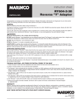
The 57' Symbol Motoryacht is a traditional yacht design, with fiberglass hull, cabin, swim step
and flybridge structures, and stainless steel welded fittings and handrails. The window frames are
of aluminum with sliding glass panes, while the windshield frame is of the same material.
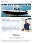
Of particular note are the easy
walk-around decks, enabling safe, secure
passage about the boat by passengers
and crew. At the stern, the swim step
has rails (as in the photo) that make it
safe; a small cabinet on the port side
holds a swim shower and a salt water
faucet, while on the starboard another
holds a hose for filling the bait tank. A
swim ladder is midships.
The big cockpit is especially useful for fishing and for dinghy handling
after launching it from its electric davit
on the stern, and there is a sink (with
cabinet beneath for engine controls), and
a bait well with pump mid-transom, and
to port of it, a small storage cabinet. A
Lifesling rescue system is also on the
Symbol Model 557 Pilothouse Motoryacht (Sistership)
transom. Two hatches provide access to
the roomy lazarette beneath containing
water tanks, Northern Lights generator, furnace, water pumps, shore power adapters, etc. The steps
at the base of the ladder from the cockpit to the flybridge are also an engine room door; just inside
it to starboard are emergency flares, fire extinguishers and first aid kit.
Hidden behind a small “door” on the starboard side of the hull just forward of the stern (not
visible in the photo) is the primary-usage 50-amp, 50-foot shore power cord automatically stowed
with a “Cablemaster” system. When the shore power cable is to be disconnected, the shore power
switch in the electric panel in the salon should first be turned to the “off” position to avoid arcing
which could damage the plug contacts. Shore power connector adapters are in the lazarette.
From the cockpit the boat’s cabins can be entered through the sliding door into the salon or
through the port side pilothouse door. Up the steps is the sundeck and flying bridge, and from there
the cabins are accessed via the stairway to the pilothouse.
The deck up the steps and ladder above the cockpit is the “boat deck”. Here you will find the
ship’s dinghy with its 20hp, electric start and tilt Honda outboard motor; Nick Jackson low-profile
davit; and a Sea-Freeze freezer (not in the photo) and the ship’s Radar arch.
Forward topsides is the flying bridge area with, to starboard, a wet bar cabinet with electric
Jenn-Air barbeque, an icemaker, and sink. To port there is an L-settee and two additional helm seats
seating 6-7 crew, and the upper helm station. A Bimini top provides shade, and storage under the
helm holds several life jackets and the Bimini “boot”. When under way, the canvas covers may be
stowed here or under the settee; the settee can also be used for provision storage.
The flybridge helm has compass, depth sounders, VHF, fixed autopilot control, a radar, a
display for the ship’s navigation/computer system, rudder indicator, electronic compass and course
display, and searchlight control. There is also a rudder angle indicator, electronic engine instruments,
4.1 - General Description & Operating Suggestions
a bow and stern thruster control, windlass control and intercom; and the MMC electronic engine
controls. Just beneath the helm is a hand-held fire extinguisher.
On the side decks are the two water fills, one on each side just forward of the cockpit; (the
water tanks can be cross-connected to allow filling from just one side). There are fuel fills on each
side, and just as with the water tanks, they can be cross-connected. On the starboard side are
located the two pumpout ports for the two holding tanks (do not mistakenly fill them with Diesel!)
On the port side of the boat about midships are an extra 50-amp shore power connection and
connections for phone and TV cable.
Forward on the bow deck is the anchor windlass, with foot switches, allowing chain
movement both “up” and “down” electrically. The anchor is retracted into the bow roller which
hangs out over the bow to give better chain clearance from the hull than otherwise possible. After
passing over the winch, the chain goes below decks via a hawse pipe in the foredeck. Compartments
on each side of the anchor pulpit permit line/rode storage: on the starboard side, the compartment
also has faucets and hose for fresh or salt anchor/deck washdown use.
Interior Accommodations:
The boat is entered by
the aft salon door (the only
door that can be locked from
outside) or by the port side
pilothouse door if it has been
unlocked from inside. The
salon door is fitted with
strong lock; the doors should
be closed when underway
except at very low speeds in calm waters to avoid getting salt water inside
the doorways.
Proceeding forward into the salon from the
sliding door, to port, there are an end table, a sofa
with a high-low cocktail table, and a high passthru/serving bar separating the galley and the salon.
In the face of this bar are cabinets holding the
entertainment systems including a TV, stereo, CD
Salon Starboard Forward
Salon Port Forward
changer, satellite receiver, remote controls, etc.
To starboard in the salon is an end table; a
sofa; and the bar cabinet, with drawers including one for
bottles, and the #2 fridge. This is under the stairway that
makes access to the flying bridge convenient and safe.
Vacuum-cleaner outlets are under it, and elsewhere
through the boat. Note: A couch in the illustrations has
been replaced by 2 lounge chairs.
Forward from the salon, the galley is up two
steps, providing a nice “break” and adding to the salon Salon Bar, Fridge #2
ambiance. The galley has an under-counter fridge, a four- and Flybridge Stair
element electric stove top, built-in convection/microwave
Galley: Stove, Oven, #1
oven, trash compactor, and dishwasher, as well as
Fridge, Dishwasher,
commodious cabinet space for supplies.
Trash Compactor, and
Microwave.
Up the steps just forward of the bar cabinet and next to the flybridge
stairway is the pilothouse area. To starboard are the steps leading to the
flybridge above; in these steps there is storage, and aside them in the cabin side are several cabinets;
4.2 - General Description & Operating Suggestions
the one between the ship’s clock and barometer hold a rechargeable, portable searchlight with its
charger (the boat also has a fixed searchlight). Another cabinet by the lower steps is for chart books,
etc.
Just past the steps to starboard is a comfortable U-shaped dinette, on a slightly raised floor;
in the floor riser are two chart drawers. Forward of the dinette a cabinet holds the “Ocean PC”
computer for the navigation systems. Center-forward in this area is the main helm, with a wing to
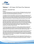
Pilothouse Helm of 57' Symbol “Ocean Spirit”
its left. Zvaardvis helm seat provides comfortable seating for the helmsperson.
At the helm, only the center portion of which is above, the operator is given a wide variety
of quality instruments to aid in vessel operation, supervision, and navigation. In the photo above
(from left to right, by columns) are the hailer, VHF radio, and stabilizer controls; the Radar, searchlight
control, and port engine instruments and switches; a course indicator, data display, rudder indicator,
and thruster controls; the computer-plotter and TV camera display, and starboard engine instruments
and switches; the autopilot control, depth sounder, and MMC engine gear/throttle controls; and the
GPS and anchor chain indicator. A handheld fire extinguisher (not visible) is on the lower right below
the wheel. (An infra-red “mouse” for the computer can be seen lying on its side on the extreme right
of the image; it has been replaced by a wired mouse.)
In the photo above, on the face of the cabinet, are the stereo
controls, an autopilot remote that makes operation easier for the helmsperson
when seated, and controls for the stereo speakers. The two switches control
the Diesel furnace system: One provides for heater operation either using
heat from the furnace or from the running engines; the other provides for
circulating heat from the furnace through the engines to warm them in
extremely cold weather — usually unnecessary in the Northwest’s warm
Ocean Spirit Pilothouse
climate.
Helm Left Wing
4.3 - General Description & Operating Suggestions
To the left of the helm on the face of the cabinet wing (to left of the intercom) are the
Northern Lights generator control panel, the KVH Tracvision Gyro panel, and a cup holder; atop the
wing are the fuel and water tank gauge, the holding tank level indicators, the bilge pump switches,
and a panel with warning lights to indicate any pump operation and to show the anchor light status.
To port of the helm wing are the steps down to the staterooms
and heads. Alongside the stairway is a storage cabinet containing the
ship’s manuals in an indexed set of binders: See page 1.2 above.
Down the steps, the master stateroom is midships beneath the
pilothouse and galley, with an island queen berth on the centerline with
drawers and the ship’s hot water heater beneath. On each side of the
berth there is a dresser/night stand, while to starboard are two hanging
lockers on each side of a long dresser with 6 drawers. Forward to port
above the hanging locker is a cabinet with tambour doors for the TV.
Master Stateroom Midships
A cabinet is in the bulkhead forward of the locker. Adjacent to the
stateroom door to port is another hanging locker with three drawers below it.
To port in the master stateroom is the door to the master head
compartment, with a roomy stall shower, vanity with sink, and Vacu-Flush
toilet. Storage is beneath the vanity, and a large cabinet is in the wall above
the toilet. Excellent illumination is provided not only here but throughout the
M/S/R Port Side
entire vessel, and there are exhaust fans in each of the boat’s two heads.
Going forward from the master stateroom in the companionway, the
stairs to the pilothouse are to port and just past them is one of the two doors
to the guest head compartment— the other door is from the forward VIP guest
stateroom as noted below.
At the forward end of the
companionway
is the #1 guest stateroom with
M/S/R Starboard Stb.Side
a centerline queen berth. Down each side are
a hanging locker and two dresser drawers,
while two more drawers are in the foot of the
berth. A TV is in the port aft corner. The aft
bulkhead of the room has the head
compartment door and the main room entry.
To starboard in the companionway
VIP Guest S/R #1 Looking Fwd
across from the stairs, a locker holds the
boat’s washer and dryer, and just forward of
that is the door to the guest #2 stateroom. In the #2
stateroom there is an upper and lower berth, a
Master Head Forward hanging locker, two drawers below the lower berth,
and a TV nook.
The guest head compartment includes a shower
stall, sink, Vacu-Flush head, storage under the sink and an #1 Guest S/R looking to
Port
exhaust fan.
Part View Guest
S/R #2
4.4 - General Description & Operating Suggestions
Engine Room:
Access to the engine room is through the lockable doorway which forms
Ocean Spirit
Engine Room
the lower steps from the cockpit to the boat deck. As you open the door, secure
Companionway
it with the hook provided so this heavy panel does not swing shut when you grab
Port Side
the rail!
The engine room light switches, both AC and DC, are on the port side of
the entryway (the engine room lighting breakers must be “on” in the electric panel
for them to work).
Immediately to starboard of the ladder are the emergency flares, fire
extinguisher and first aid kit (note the picture to the right).
The engine room layout is roomy, and there is standing headroom.
Here is the engine room arrangement: The two, 425-gallon fuel tanks are
about 36" back from the forward bulkhead on each side. Forward of the port tank
is a set of shelves for parts storage, beneath which is the port stabilizer hydraulic actuator. Forward
of the starboard tank is the starboard stabilizer actuator and
the built in vacuum cleaner unit. Across the front bulkhead
from port to starboard are two step-up transformers for 220
volts; the three Racor fuel filters for the two engines and the
generator; the large built in fire suppression system, a fresh
water hose on a rack for use in watering the engines or in
cleaning; the Pro-Sine sine-wave inverter for the ship’s
computer system; the manifold for the stabilizer hydraulic
system; and the hydraulic reservoir.
The Caterpillar 3196TA 660hp engines are on each
side of the centerline; forward of them in the bilge are their
sea strainers and seacocks. Above each engine forward are
Ocean Spirit Engine Room Looking Fwd.
the Mathers MicroCommander servo boxes with push-pull
Morse cables to each engine’s throttle and transmission, while above the port engine aft is a Mathers
junction box. The oil dipsticks are on the inboard engine sides as follows: Port engine, just aft of the
instrument panel; starboard, by the fuel filter. The oil fills are forward on both engines with large
caps, while the cooling water/antifreeze is added/checked beneath caps top front center of each
engine on the coolant tanks.
Aft of each engine is its transmission and shaft with a shaft wiper for shaft grounding; the
shafts pass through into the shaft tubes outside the boat through dripless PSS shaft seals lubricated
by engine-supplied sea-water hoses.
At the aft end of each fuel tank is a large valve to a
crossover hose to allow fueling both tanks by opening the
valves; the valves should be closed when not fueling so as to
avoid leakage should the hose fail.
Aft of the port fuel tank is a fuel transfer pump with
valves to allow tank balancing if necessary. Centered on the
aft bulkhead are battery boxes with a workbench above, and
above it, the battery switch panel, inverter control and main
Heart inverter. Under the batter switch panel to the right is a
battery charger.
At the aft end of the engine room to starboard are two
Engine Room Aft Bulkhead and Battery
more
battery
boxes and the steps to the cockpit; in both aft
Switch Panel Looking Slightly to Port; the
Oil Cans are sitting on the Workbench...
corners of the engine room are manifolds tying together the
4.5 - General Description & Operating Suggestions
various drains go into a single overboard thru-hull to avoid having to many hull-openings; each thruhull both below and above the waterline is fitted with a seacock in case of accidental vessel
grounding.
Lazarette
Entered from the cockpit through either of its two hatches, the lazarette holds the Northern
Lights generator mounted in its center (with life jacket storage in two bags atop it); and the rudder
posts and steering gear (with emergency rudder rigging) mounted aft. To port at the side of the
vessel there is the furnace system, the generator battery in a box, and the heating system fluid
manifold for distribution of heating fluids throughout the vessel.
To starboard in the lazarette aft corner are the water pumps with their accumulator tanks
above (both salt and fresh: Most forward is the fresh water pump, and just aft of it are two salt water
pumps fed by a sea strainer just aft of them), while on the forward end athwartships in the lazarette
are the ship’s water tanks and, above the generator, its control panel and breakers. Just as with the
fuel tanks, the water tanks are fitted at their aft side with a crossover hose and valve, and as with
the fuel tanks, the crossover valves should be closed when not filling the tanks.
Also in the lazarette are stored extra shore power cables, lines, and other miscellaneous gear
including emergency anchor, anchor rode, and large fenders.
Dinghy:
The boat is equipped with a four-person, 10-foot AB RIB inflatable dinghy equipped with a
four-stroke 20hp Honda electric-start, electric tilt outboard motor, starting battery, a regular and a
spare fuel tank, a built in modular battery charger for winter or emergency use, and oars. It is
launched by use of the electric Nick Jackson low-profile davit. Note that the davit control is kept
under the flybridge console behind the port-side door.
Deck Equipment:
The boat has mooring lines; a stern/shore line; an CQR anchor with 375' of all-chain rode;
six fenders/bumpers in racks on each side of the foredeck; an ice chest for picnics, etc; a crab ring
with line, float, and bait rigging; a hose for fresh water tank filling and boat washing; and a boat
hook.
Safety Equipment:
•
•
•
•
•
•
There are four electric bilge pumps situated in the forward hold, guest companionway hold,
engine room and lazarette controlled by the breakers and switches at the helm.
This vessel is equipped with six fire extinguishers: one in the pilothouse below the wheel; one
on the flybridge below the wheel; in the engine room by the steps, in the washer-dryer cabinet
in the companionway, and a fire suppression system in the engine room.
The boat also has two VHF radios, one at each helm station.
Flare kits with both outdated and current flares, and a first aid kit are in the engine room
entryway and flares are also in the flybridge console port cabinet.
A dozen life jackets in two life jacket carrying bags in the lazarette atop the generator and under
the flybridge console are carried.
A “Lifesling” throwable PFD is stowed in its bag on the transom.; if necessary, it can be hauled
with the dinghy davit.
Charter clients with children under 90 pounds should bring appropriate life jackets for them!
4.6 - General Description & Operating Suggestions
MANEUVERING & OPERATING SUGGESTIONS
Docking & Undocking
Usually it’s easier to dock bow in, and this boat is most convenient when the starboard side
is on the dock with the swim step accessible.
Have your mate at the side rail opening or on the swim step, ready to step off and secure the
stern line, against which you can pull to swing the bow in toward the dock. By having your mate
ready to disembark when close to the dock, he/she will not have to jump to the dock, risking a turned
ankle or falling overboard. It is the
skipper’s job to put the boat next to the
dock so the mate needn’t jump, but
merely step off!
Approaching a dock, have
fenders out as required and have the
bow line already rigged, passed through
the opening in the hull under the rail, and
draped back on the side of the boat
outside the stanchions so it can be
reached from the dock. Never put a line
from a cleat over a rail: the boat’s weight
will bend or break the rail if it pulls against the line! When the mate’s ashore, the line can be easily
reached!
If dock clearance permits, spring the boat forward so that it pulls forward on the stern line.
This will bring the stern close to the dock. Let the bow line out enough so that the boat can rest
against the stern and midships fenders. The small, pop-up cleats on the side toerails are for fenders;
the pop-up cleat on the swim step will permit holding the boat close in to the dock.
Maneuvering in a Harbor
With its twin screws, you’ll do best if you center the rudder and steer with the engines only!
The props are so large that the boat will respond well except in high winds just with use of the
propellers in forward and/or reverse. Take your time, and keep the boat running “dead slow” so that
you can plan each approach. You shouldn’t need to use the throttles at all.
Bow and Stern Thrusters
Ocean Spirit has been equipped with a Nobels bow and stern thrusters with “joystick”
controls at each helm and in the cockpit MMC remote control box. To operate, simply push the
“joystick”! Limit use of the bow thruster to “bursts” of no more than 15 seconds at a time to avoid
overheating the electric motors. Remember after using the bow thruster to get the shore power
connected, or run the generator! See Ship’s Binders Volume #5.
Filling the Fuel Tanks
With the large fuel tanks, you can fuel the boat moderately quickly as long as you use a small
nozzle such as those found on auto gas pumps. You can control the flow rate by sound, as the fill
pipes make the characteristic “getting to the top of the bottle” pitch change when the fill pipes begin
to fill when the tanks themselves are full. (The tank vents will gurgle before the tanks are full, so
when the vents begin gurgling, slow down until you hear the fill pipes’ pitch change.) You also may
want to open the cross-pipe valves on the aft side of the tanks so both tanks are filled at one time!
Please close after filling!
READ CAREFULLY! Fill the tanks ONLY until you hear the fuel reach the fill pipes. Better to
4.7 - General Description & Operating Suggestions
under-fill them a little, than over-fill them! You might have a mate watch the sight gauges.
Anchoring
Anchoring can be accomplished safely with a minimum of fuss if you are prepared. Or, if you
are not ready, it can be stressful and dangerous for you or the boat.
Before attempting to anchor, select an anchorage with a soft bottom such as sand, mud, or
gravel, if possible. Look at the charts and cruising guides for tips on good locations. Then, choose
the spot in the anchorage where you have room to “swing” on the anchor without disturbing other
boats. Remember, responsibility for leaving room goes to each successive boat to arrive, for the first
boat has priority in the anchorage!
Here in the Northwest, because of the deep waters, the boat’s all-chain rode and small bays,
we anchor a little differently than in the Gulf of Mexico or Carribean, for example. First, except in
severe weather, we use anchor chain scopes of only 4-to-1 or 5-to-1. For example, in water that is
40 feet at high tide in the typical anchorage, we might use 160 feet of chain unless the weather was
to be gale force or greater winds.
Second, because of the small bays and steep bottoms, we often rig a shore line from the
stern of the boat to shore. The best example of this would be at Todd Inlet at Butchart Gardens:
Here is a bay that can accommodate 8 - 10 boats, yet it usable depths are only about 150' wide and
200' long! Boats attach their bows to the mooring buoys or, in a few cases, anchor; and then their
sterns are secured to rings provided in the steep cliffs overlooking the bay. Boats are thus perhaps
only 15-20' apart, side to side.
Third, boats often will “raft” side by side in busy marinas, although this is not too common.
Fourth, courteous boaters will call vessels coming into busy bays and offer to let them raft
to the same buoy, if signs on the buoys do not limit usage to only one boat depending upon length
(likely for this 57" Symbol!)
Anchoring safely requires two persons, one at the helm maneuvering the boat and one on the
bow carefully watching the anchor and operating the anchor foot switches.
1. Putting the bow of the boat over the spot where the anchor is to be placed after
checking the depth on the depth sounder, the windlass foot-switches are used to lower
the anchor slowly toward (but not onto) the bottom, while the helmsperson watches the
depth meter on the helm.
To use the depth meter, press the bottom left (power) button briefly; the display
will come on. Press the “M” meter button to zero the meter. Then use either the
up/down buttons on the panel or at the chain to operate it; the meter will show
approximate feet of chain overboard.
2. When the anchor is about to reach bottom, the boat is backed away by putting the
engines into reverse for 5 seconds: eddies from the chain indicate motion. Resume
lowering the anchor while drifting backwards (watch the eddies and add another burst
of reverse if necessary!) until the desired amount of chain is out. Stop paying out chain.
3. Engage reverse for five seconds at a time until the chain starts to pull straight off the
bow toward the anchor. A straight chain indicates a “set” anchor!
4. NEVER pull on the chain for more than five seconds, and never at any engine RPM other
than idle! Putting the boat’s weight plus its horsepower on the chain forcefully even at
idle will bend the anchor and/or damage the mooring gear!
5. If while checking the set, the chain rumbles and clunks, and seems to release in bursts,
it means you're anchoring on a rocky bottom and the anchor is not holding. Be patient:
it may not set on the first try, and you'll have to repeat the process sometimes to get
4.8 - General Description & Operating Suggestions
6.
a good "bight" on the bottom.
When hauling up the chain, be sure to note how the chain is self-stowing in the chain
locker under the anchor! Approximately the first 100' of chain into the boat (leaving
about 275' to the anchor) should be hand-stowed into the starboard locker: This will
involve pulling the chain as you haul it into the right side over the “wall” separating the
starboard and middle compartments. The balance can go directly into the center. If the
chain stacks up into a pyramid under the windlass, knock it down with your foot or a
boat hook so that there is enough room under the windlass for all of it. If you have put
out more than 250' of chain or so, this means that haling anchor will be somewhat
demanding, but there’s no easy solution for this problem that has been as yet found.
Shore Lines
When a shore line is required, anchors are set 150 - 175 feet from shore, with the boat
backing toward shore during anchor-setting. The stern line is put around a tree, and brought back
to the boat.
During this process, be sure to keep clear of rocks near the shore, and allow for our
Northwest tides, occasionally twelve feet, and sometimes 20 feet when further north! Check the
present tide, and high and low tides before beginning anchoring: No sense anchoring in 15 feet of
water if you're at the "top" of a 15 foot tide!
To get to the shore, you will need to have a dinghy down, and then have your mate keep the
boat's stern toward shore with short bursts of reverse gear. Sometimes a helpful boater already
anchored will help you by taking your line to shore for you with his dinghy, a neat "good deed" that
you might reciprocate. We've met some nice boaters this way!
The shore line is in the lazarette, and is long enough to usually allow taking it to a tree,
around it, and back to the boat so you don't have to go ashore to untie when leaving. With a crew
member keeping the boat in position, take the dinghy to shore pulling the end of the shore line with
you. Pass it around a tree, and pull it back to the boat if you can, since then to get away in the
morning all you have to do is release the bitter end from the boat, and pull it aboard. Pull the line
tight, as long as you've got over 100' total of line out: there is plenty of sag/stretch, and we want
to keep the boat in its area! If necessary, put a crab pot float or fender on the line to warn others
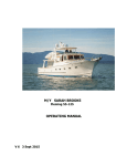
it’s there. Here is a sketch of a properly anchored boat with a shore line (In this drawing, S=Scope,
which should be at least 4 x DL, the Depth at Low Tide):
4.9 - General Description & Operating Suggestions
Picking Up a Buoy
Picking up a buoy off Ocean Spirit is not as difficult as with some other boats that are
motoryachts without a cockpit and the easy walk-around decks. You can avoid trying to “pick up”
a buoy with a boat hook or what have you by following these steps:
1. The mate is on the swim step with a long line in hand, calling positions to the skipper.
2. The helmsperson puts the step next to the buoy with a mate standing by.
3. The mate loops one end of the line through the buoy ring and then, with the ends
together and the buoy in the middle of the loop, walks forward to the bow, securing the line
on the two bow cleats forming a “bridle” between the boat and buoy.
4. The swim step door is closed and secured.
Trim Tabs
The boat is fitted with a set of Bennett Trim Tabs. These are wide “flaps” attached to the
aft end of the boat, under the swim step at the trailing edge of the hull, operated hydraulically under
the control of the skipper by rocker switches at each helm station.
At low speeds, up to approximately eight or nine knots, the tabs do little, and should be left
in the “Bow Up” position (see below). But at speeds over this range, the tabs begin to take effect
and will help the operator lower the bow for more efficient cruising.
The best way to adjust the tabs is to lower them while watching the “Speed” indicator to get
the highest speed at a given throttle setting by adjusting “Bow Down”. If the tabs are “Bow Down”
too much, the steering will get mushy and speed may drop off a little, and the tabs should be
adjusted “Bow Up” a little. Note that it will take time to make these adjustments; when the buttons
are depressed, they need to be held 2-5 seconds each time for change to be felt and observed (the
best way to see the effect of the tabs is by the knot meter and by observing the height of the bow
relative to the horizon).
Because the trim tabs are so large, THEY MUST BE IN THE FULLY-BOW-UP POSITION
WHENEVER THE BOAT IS TO BE OPERATED IN REVERSE, otherwise the great water forces against
the tabs may damage them severely, even tearing them off the hull!
Anchor Monitor
The windlass breaker needs to be on for this to work. Push lower left button to turn on; then
push and hold upper left button to move cursor to top of the display. The unit will show “00.0" in
top of window; this is meters. When the cursor reaches the top, it will read “000", this is feet. The
bottom right arrow lets chain out, upper arrow retrieves the chain, and the gauge lets you know how
much is left to retrieve. You must keep the anchor windlass breaker “ON” to keep the meter’s
readings whenever the anchor is down!
SPECIAL CARE needs to be taken when the chain is stacking in the locker, you must keep
moving the chain away from the pipe or it will back up and foul the chain. We suggest
using the boat hook to poke the chain out from under the hawse pipe every fifty feet or so!
4.10 - General Description & Operating Suggestions
SECT. V: SPECIFIC DISCUSSION OF BOAT SYSTEMS
This section of the Owner’s Notes will discuss each of the boat’s systems in turn. The
systems and major components discussed are grouped and in order as follows:
Main Engines, Sea Strainers and Fuel System
Dinghy, Davit & Outboard Motor
Fresh Water & Sea Water (Washdown) Systems
Electrical-AC, Electrical-DC, Generator & Inverters
Heads & Holding Tanks
Heating System
Stabilizers
Galley & Laundry Equipment
Electronics: Navigation Equipment, Radios, & Radar
MAIN ENGINES
The main engines on the boat are two Caterpillar Electronic-Control 3196TA turbocharged,
intercooled Diesels, each producing a maximum of 660 horsepower at wide-open throttle (WOT) and
2300 RPM. These extraordinarily-reliable, rugged machines are the top-of-the-line, and can be
expected to give you trouble-free, economical cruising.
On engine start, no long warm-up is required! Three or four minutes is sufficient, then load
the engines by putting the transmissions in gear. Do not run them over 1400 RPM until the
temperature gauges read at least 140° Fahrenheit. Do not run the engines for long periods with the
transmissions in neutral, with no load!
The engines require a regular, daily check, since once underway, you will probably not check
them while in use, tucked away as they are beneath the salon floor. Please perform this check each
morning (when the engine room is cool!):
! CHECK THE OIL. The oil level should be between the two marks on the dipstick. The
dipsticks are located on inboard side of each engine as follows:
The port engine dipstick is just aft of the engine-mounted instruments;
The starboard dipstick is slight further forward by the fuel filter.
The sticks “pulls out” upward. Use a paper towel from the roll supplied on the overhead
holder just aft of the starboard engine, wipe the stick, reinsert, guiding the stick with the
towel to keep from bending it, and take the reading. When done, be sure the stick is fully
inserted to avoid drips...
The distance between the two marks is about 2.0 quarts. Add only enough Chevron
Delo 400 SAE 15W-40 oil to bring it up above the “add” mark, say a quart, using the
oil provided on the boat. (If you need more oil, buy it! We will reimburse you.) The
oil fill on each engine is a large cap forward on the inboard side of each engine. Be sure
to tighten the cap after filling.
DO NOT OVERFILL the crankcase (above the “full” mark), as these engines will quickly waste
excessive lubricant. If oil is required often, check under the engine carefully to be sure there
is no oil leak, and if there is, have it corrected promptly.
! CHECK THE COOLANT LEVEL.
The heat exchanger coolant tanks are located on the forward end of each engine, with
caps on the top. Remove the cap by turning; you will have to press the cap down and
5.1 - Systems: Engines
turn it past the second detent to get it off. Put a finger into the tank; if your finger
gets wet before it hits the baffle inside the tank, there is enough coolant!
If coolant is needed, determine if there is any sign of a coolant leak under the engine, and if
there is, do not run the engine; if no leak, add coolant to the tank from the jug of pre-mixed
antifreeze/corrosion inhibitor/water supplied on the boat. In an emergency, water alone can
be added from the water hose hanging on a holder in the forward center of the engine room.
! VISUALLY INSPECT THE ROOM whenever you’re in the engine room, asking yourself, “Does
everything look right?”. Look at the pads under the engines and transmissions: while some
drips are normal, there shouldn’t ever be substantial accumulations of any fluids!
! CHECK THE SEA STRAINERS ONCE A WEEK, or immediately if either engine runs “hot”,. The
engine strainers are forward of each engine. To check a strainer, shine a flashlight through
it. While some “fuzziness” from trapped thin growth is normal, you should see the light clearly
on the other side; if obscured, you should clean the strainer. See below.
! CHECK THE TRANSMISSION OIL LEVEL if a transmission shifts erratically, with the dipstick
on the starboard side of each transmission. It is unlikely that any oil will need to be added.
Be sure to check under the transmission for leaks! Low transmission oil is a serious matter.
With the engine idling, remove the transmission dipstick. Wipe it with a towel, reinsert it, and
take a reading. If the level is below the add mark, stop the engine, add a pint of Delo 100
SAE #30 oil for the engine crankcases through the plug in the top of the transmission case,
and then start the engine and measure again. Do not overfill, for to do so could cause the
seals to “blow out”.
These engines are red-lined at about 2300 RPM. Maximum cruise is 1900 RPM. However,
the realities of hull design and power plant engineering dictate that higher RPM operation is very
inefficient on semi-displacement vessels like this one, so you will find these operating specifications
to be true (All fuel, range, and speed figures are estimates and for both engines combined!):
RPM Est.GPH Est.Knots Est.K/Gal Est Fuel Hours Est. Range with Reserve
800
2
8
4.00
375.0
3000.00
900
4
8.7
2.18
187.5
1631.25
1000
7
9.4
1.34
107.1
1007.14
1100
8
10
1.25
93.8
937.50
1200
16
11
0.69
46.9
515.63
1400
20
11.8
0.59
37.5
442.50
1500
25
12.6
0.50
30.0
378.00
1600
29
13.8
0.48
25.9
356.90
1700
33
15.5
0.47
22.7
352.27
1800
39
17.8
0.46
19.2
342.31
1900
44
19.1
0.43
17.0
325.57
2000
50
20.3
0.41
15.0
304.50
2200
64
22.6
0.35
11.7
264.84
In the table, “K/Gal” equals nautical miles per gallon. “Fuel Hours” and “Range” assume 750
gallons used, 100 gallon reserve, and no current/tide correction.
As you can see, each extra knot is very expensive once you have passed “displacement
speed” on the vessel hull; this is not a “planing” boat! It is sensible to operate the boat in the 11001200 RPM range, and you’ll enjoy quieter, more pleasant cruising and economy, too!
Red marks on the engine gauges show normal operating parameters!
Full CAT Engine Manuals are in the Ship’s Binders Volume 8.
5.2 - Systems: Engines
Mathers Micro-Commander Controls
Ocean Spirit is fitted with electronic MMC controls that combine the throttle and shift in one
lever. They have the following advantages: (A) They are very easy to operate, with no “drag”; (B)
They prevent the operator from shifting from forward to reverse, or vice versa, too rapidly, thus they
protect the engine reverse gears; C) They automatically synchronize the engines.
HELM CONTROLS
The button labeled “Transfer” on each set of controls activates that station; push it when you
arrive at the station after leaving the other, i.e., when you go to the flybridge, press the button there
to TAKE control. If you HOLD the button in as you advance the lever into the forward position from
neutral, the light will blink and the engine will not shift, and so you can thus fast-idle the engine.
HANDHELD CONTROL
To operate the boat from the aft cockpit, it is equipped with an MMC handheld control box,
stored in the cabinet under the sink in the port forward cockpit corner. The control has a “transfer”
button and switches for the two thrusters on its front, and knobs controlling the shifters and throttles
on each side. At the top, there is an emergency “Stop All Engines” button.
1.
Be sure the knobs are in the neutral “detent” position;
2.
Press the “Transfer” button on the control box;
3.
Operate the engines with the knobs, and the thrusters with the switches.
ENGINE SYNCHRONIZER
This function should be off when starting or maneuvering. With transmissions in forward gear,
select either port or starboard with the switch; a “>” will appear in the engine’s digital display. Now
just use that engine’s throttle to control speed and ensure that the engines are synch’ed.
TROLLING VALVE
The transmissions are equipped with “trolling valves” that allow the boat to run at low speeds
when idling. To operate, (1) Stop the boat in neutral; (2) Turn on the “Trolling” switch at the main
helm; (3) put the boat in gear and operate as usual. An “*” will appear in the digital display. Note:
Do not run the engines at high speeds for long periods with the trolling valves switch on (even though
the Mathers Controls accommodate this automatically! Instead, turn the valves off and run the
engines at idle!
Full Mathers Controls Manuals are in the Ship’s Binders Volume 5.
Sea Strainers & Seacocks
The sea strainers on this boat are secure and reliable. They protect the engine, generator and
washdown systems from water-borne debris which might block internal equipment passages.
Seacocks are the valves that close off any pipes going through the hull, in or out. Located
throughout the boat, they allow the seawater inlets to be turned off, and additional seacocks allow
all vessel thru-hull outlets to also be turned off in case the vessel is grounded and because of listing
would otherwise have water enter the hull. Except as noted for the starboard engine as below, all
seacocks are “off” when their handles are parallel to the hull (at right angles to the seacock itself),
and “on” when they are perpendicular to the hull (in line with the seacock itself).
If a sea strainer needs cleaning (see above regarding inspection) here is the procedure:
5.3 - Systems: MMC Controls, Seacocks & Strainers
1) Turn off the seacock valve leading to the sea strainer.
NOTE: The Starboard Engine Seacock (only) is Non-Standard: It is CLOSED when IN
LINE with the Valve, OPEN when PERPENDICULAR to the Valve!
2) Remove the top of the strainer. Save the gaskets!
3) Open the seacock valve briefly. Water should “gush” into the strainer, washing out the
debris. If it doesn’t, manually clear the obstruction at the thru-hull and/or clean the strainer
water entry.
4) Replace the strainer, gasket, and cover, securing it tightly.
5) If the strainer was not blocked, it is likely any overheating was due to a failed impeller in
the sea water pump, or the pump’s belt is broken. Replace it if you know how; otherwise,
call the charter company or a mechanic for assistance.
This entire operation will take 5-10 minutes at most, and will assure you of cool engines.
Replacing a pump impeller is simple:
(1) With the seacock closed, follow the hose from the strainer to the pump;
(2) remove the back plate (opposite end from the pulley);
(3) you'll see the impeller, shaped like an "asterisk" ("*") and it will likely have one or
more broken or damaged "arms" on the asterisk (if no arm is broken, the problem isn't
the impeller, consult a mechanic);
(4) if an arm is broken, slide the impeller out of the pump where the cover plate was;
(5) clean out the pump chamber, trying to get all the pieces out of the water system;
(6) lubricate the new impeller with hand soap or dishwashing detergent;
(7) aligning the "flat" on the shaft with the matching "flat" on the impeller, and
pushing the blades aside as required, slide the new impeller into the pump;
(8) replace the cover with its gasket and tighten its screws or bolts securely. OPEN
THE SEACOCK.
(9) start the engine and check operation, being sure water is flowing from the exhaust.
To loosen, tighten, or replace a belt:
(1) Loosen the three bolts that hold the angle brackets together using an open-end
wrench from the tool box. These bolts are just above the pump, oriented with their
heads on top of the bracket, with the bolts pointing down to the bilge.
(2) Slide the water pump as required.
(3) Re-tighten the bolts securely!
A Complete Drawing showing all Seawater Locations is in the Ship’s Binders Volume #2.
5.4 - Systems: Seacocks & Sea Strainers
Fuel System
The fuel system for Ocean Spirit is not complicated. It is comprised of a fuel measurement
system for fuel measurement at the pilothouse helm, and the fuel valves for fuel going to (feed), and
returning from (return) each engine (excess fuel is pumped into each engine’s “injection pump”, and
this excess fuel cools the pump during engine operation...that is why on larger Diesels, there are
“return lines”).
The feed valves and their associated pipes with multiple connections (the fuel manifold) are
located in the forward end of the engine room, in front of the port engine, while the return lines and
valves are above this engine. This plumbing is schematically shown in the FUEL SYSTEM drawing in
the Symbol Owners Manual, Volume 2 of the ship’s binders.
The fuel valves are normally set so that each tank is connected to its respective side’s engine
through that engine’s fuel filter (the generator is feed from the same tank as the starboard engine).
Two “Crossfeed” valves allow these normally-separated feeds and returns to be joined, and then if
a single tank supply and return valve is closed, all machinery draws from the one open tank.
Remember, when a valve’s handle is in line with the pipe, it is “on”; when it is “across” it, it is “off”.
A Complete Drawing showing the Fuel System is in the Ship’s Binders Volume #2.
Fuel and Water Measurement
You can tell fuel and water levels fairly accurately by the Wema Norway Tank Level Indicator
instrument on the left wing of the pilothouse helm. Turn on the instrument with the left knob, then
set the switch for the tank you wish to read where “1"= Port Fuel, “2" = Starboard Fuel, “3" =
Port Water, and “4" = Starboard Water. The WEMA gauge is moderately accurate: Tank “1" is
usually correct; Tank “2" is accurate below one-half. The water gauges (3 & 4) are close. But it is
best to use the sight gauges!
You can check levels very accurately by checking the sight gauges located on each tank. For
fuel, they are at the forward end of the tanks in the engine room and 1" equals 11.2 gallons. For
water, the sight gauges are on the tanks in each side of the lazarette, and each inch is 3.0 gallons.
Both the upper and lower valves must be open (in line) for the sight gauge to work accurately.
Fuel Transfer Pump
A fuel transfer pump is in the port aft engine room corner just forward of the workbench. This
reversible pump can shift fuel from one tank to another if necessary to trim the vessel. After turning
the breaker on in the main power panel, open the valves and run the pump in the appropriate direction
using the switch on the motor. When done, shut it off and be sure to close the valves! (A sight
gauge on the forward bulkhead between the engines will help you level the boat accurately.)
Oil Change Pump
A oil change pump is located in the starboard aft corner of the engine room just forward of
the bulkhead. This reversible pump lets you empty crankcase and transmission oil into a pail in the
engine room through the hose that is stowed on the hook above the pump, from either engine or the
generator to expedite less-messy oil changes. After turning the breaker on in the main power panel,
open the valves and run the pump in the appropriate direction using the switch on the motor itself.
When done, shut off the pump and be sure to close the valves both on the pump and at the
transmissions and crankcases!
Dispose of waste oil, etc., properly!
5.5 - Fuel System/Measuring, Fuel/Oil Pumps
DINGHY, DAVIT & OUTBOARD MOTOR
Dinghy
The dinghy aboard this boat is a hard-bottom “AB” 10.5-footer, designed to carry up to four
passengers safely, with four sharing the seats. For safety, and compliance with U.S. rules, there
should be a life jacket aboard the dinghy for each passenger aboard whenever the dinghy is at sea.
Please be careful when pulling the dinghy ashore on beaches to minimize damage and
scratches to the bottom. Don’t “Ram” the beach; you can bump up to the beach gently and step
ashore over the bow, pulling the dinghy a little more ashore as each person off-loads. Don’t forget
to raise the outboard when the boat is beached!
The dinghy inflation pump is under the Flybridge L-Settee, as is its “patch kit”.
The Dinghy Manual is in the Ship’s Binders Volume #13.
Dinghy Davit
This boat has a high-quality Nick Jackson low-profile electric davit supporting the dinghy,
powered by the ship’s batteries. Using it to launch the dinghy is actually easy and quick!
1)
Be sure either the generator or an engine is running so as to keep the batteries
charged.
2)
Remove the tie down straps and cover, if any, from the dinghy
BE CAREFUL! IT’S A LONG WAY DOWN FROM THIS HIGH PERCH!
3)
Put the drain plug in the dinghy!
4)
Plug the davit control box found in the port side cabinet in the flybridge console into
the receptacle on the end of the boom housing nearest the davit’s vertical column.
5)
Let “OUT” enough cable to disengage the hook from it’s tie-down bungees.
6)
Swing the davit boom around and attach it to the dinghy bridle.
7)
Raise the dinghy until the weight above the hook is just below the boom-end pulley.
8)
Swing the dinghy around while holding it’s bow painter until it is over the water on
Ocean Spirit’s port side, and lower it all the way to the water. The second person can
tend the bow painter to keep the dinghy parallel to the boat. Let out enough cable so
the dinghy can be pulled back to the swim step for boarding.
9)
Disengage the davit hook from the bridle, AND SECURE THE DAVIT HOOK ABOARD
AGAIN IN THE PROVIDED DECK RING AS WHEN YOU FOUND IT SO THE BOOM WILL
NOT SWING IF THE BOAT ROLLS WHILE AT ANCHOR.
10)
You can unhook the dinghy bridle as necessary to have clear and safe dinghy access.
To retrieve the dinghy, reverse the procedure, using the dinghy’s painter to hold it steady and
swing it around; remember to remove the plug and re-secure the davit boom. Be careful that
the motor is tilted so that it doesn’t damage the sundeck when the dinghy is lowered!
5.6 - Systems: Dinghy, Davit & Outboard
Outboard Motor
The outboard motor for this boat is a Honda electric start and tilt outboard. This outboard is
a four-cycle motor, that uses regular unleaded gas, with no oil mixed into it. Spare motor oil is in the
lazarette.
Check the oil regularly by unlatching the cover (latch is at the rear), lifting it off, and using the
dipstick.
To start the motor,
1)
Lower it with the rocker switch on the shift lever end;
2)
Squeeze the fuel line bulb (at the boat’s stern) until it feels “hard”;
3)
Turn the key for 15 seconds at a time until it starts. (Do NOT lift the “fast idle lever”)
4)
When the motor warms up a little, you can gradually raise the fast idle lever until the
motor has warmed up a little. The lever should be down before engaging the shift.
To shut the motor off, turn the key off.
There is a spare fuel tank stowed in the dinghy.
In the event the dinghy battery should be dead, there is a built-in battery charger; use an
extension cord to plug it into the AC outlet on the flybridge.
The Honda Outboard Manual is in the Ship’s Binders Volume #13.
5.7 - Systems: Dinghy, Davit & Outboard
WATER SYSTEMS
Water Tanks
There are two water tanks located aft in the lazarette. Level indications are by the helm’s tank
gauge in the lower helm left wing (see “Fuel and Water Measurement” on page 5.5) or by sight
gauges on the side of each tank. The tanks are filled by two fills just at the top of the steps from the
cockpit in the side decks; you can fill both tanks at once by opening the cross-feed hose valves in
the lazarette at the bottom aft side of each tank. The valves for the two water tanks are at the bases
in the lazarette. Except in an emergency, both these valves should be left open so water is taken
equally from both tanks.
A Complete Water System Diagram is in the Ship’s Binders Volume #2.
Fresh Water Pump
The water line from the tanks leads to the boat’s fresh water pump in the lazarette, starboard
side aft corner (the two seawater pumps are also here). When the breaker is “On”, the pump will run
whenever its built-in pressure switch detects low water pressure. There is also an “accumulator
tank” located here; it provides a “pressure head” for the pump, so it won’t run so often. Instead, a
pump cycle provides for several minutes of routine water use before pressure diminishes and the
pump starts again.
It is a good idea to turn off the fresh water pump breaker whenever leaving the boat, lest a
dripping faucet cause the pump to run and waste your drinking water.
Hot Water Heater
After the water pump, water is distributed directly to the cold water faucet lines and to the
boat’s hot water heater located under the master stateroom berth (port side aft under a panel). This
heater uses two energy sources, (1) heat from the starboard engine, so that whenever the boat is
running or has recently run, there is hot water; and (2) 110 volts AC from shore power, if available
and the breaker is “on”. The heater is insulated well enough to keep hot water overnight without
power, provided you haven’t wasted a lot in dishwashing!
Waste Water
Waste water from the sinks and showers (but not from the toilets) is dumped overboard in
accordance with law. From sink basins, the water simply flows by gravity overboard. Since the floor
of the showers is below the water line, built in shower sump pumps operate to lift this water back
above the waterline and dump it overboard. The sumps are under the hatch in the center of the
companionway at the foot of the stairs.
It is therefore very important that the “Sump Pump” breaker in the main DC panel be left “On”,
so as to keep the shower sumps from overflowing into the bilges!
All the waste water and deck drain pipes/hoses lead to overboard manifolds in the forward aft
corners of the engine room; the manifolds then go overboard through a seacock.
A Complete Seacock Location Drawing is in the Ship’s Binders Volume #2.
Salt Water & Washdown Faucets:
Salt water is brought into the boat through a thru-hull and small filter in the starboard aft
corner of the lazarette. Water goes from these pumps to the forward washdown faucets on the bow
5.8 - Systems: Fresh, Salt & Waste Water
to port of the anchor windlass, and to the salt water faucet at the stern in the swim step. Operation
of the seawater pumps is automatic, controlled by the pressure switch built in to it. They are sent
power from the two breakers on the DC panel, which may be left on only when you are on the boat.
A freshwater washdown faucet is on the transom for the swim shower, and in the starboard
bow locker by the anchor for washing down the boat.
A washdown hose is at the forward faucet and a regular hose is in the lazarette for stern use.
For the salt water washdowns to work, both the “SALT WATER” breaker in the DC panel, and
the “SW PUMP” switch located to starboard of the ladder to the Flybridge in the cockpit must be
“ON”.
The Complete Drawings of the Water Systems are in the Ship’s Binders Volume #2.
5.9 - Systems: Fresh, Salt & Waste Water
ELECTRICAL SYSTEMS
Concepts
Electricity for Vessel Operation
Each year it seems more folks are confused by the operation of electrical systems on yachts
than by any other subject! Don’t feel discouraged if something isn’t clear: you’ve got company in
your confusion. So let’s try to cover some theory here first.
Most of the actual “boat equipment” on any boat is run by 12-volt or 24-volt DC electricity
from the boat’s batteries. This is true because DC should always be available: we have batteries
aboard even when there is no shore power! If the batteries aren’t run down, everything should work,
just like in the family car.
Since the batteries are used so much, we have to replenish, or charge them. The most
important way we do this is by alternators on the ship’s engine(s). In most cases one engine will
provide enough electricity in most every case to run everything, and still have some energy left over
to add back to the battery, that is, to charge it.
Ah, but what if the engine(s) isn’t running? Then, the batteries are slowly depleted until they
have “run down” and there is no more electricity stored in them . . . a big problem, because then we
not only can’t run all the neat stuff on the boat, we can’t start an engine to get more electricity.
So a good skipper and crew has “electrical power management” in mind whenever they turn
an electrical gadget on or off, especially when the engines aren’t running!
It is with this in mind that we can cite a reality: If we need more electricity than the batteries
alone must provide, and if a propulsion engine isn’t running, we will need to get our electrical power
from an alternative source! That’s the most important reason why we plug the boat in to shore
power or use the generator: To keep from running down the batteries. For by using battery chargers
getting their power from shore power or the generator, we can keep the batteries charged, or, at
least, from getting too low.
Electricity for Appliances and Other “Non-Boat-Operation” Items
In modern, luxury cruising boats, however, there is another important factor: Some of the
“goodies” we like to have on board such as hair dryers and microwave ovens require ordinary
household electricity. This is 110 volts AC for the smaller items, and 220 volts for the bigger ones
(just like your home ashore). AC is different from DC, and cannot be stored in batteries
So if we want to use these things when we’re not at a dock, we must have another way to
get 110 or 220 volts AC, and for this we use the generator (which runs a small, quiet Diesel engine
to make the 110/220) or an inverter, an amazing high tech gadget that takes 12 volts DC from the
ship’s batteries and makes it into 110 volts DC!
So here’s what we’ve got:
•
A lot of stuff running on 12 or 24 volts DC with that electricity from the batteries.
•
To keep the batteries from running down, we have alternators run by the engines, and
battery chargers that get their power from shore power.
•
For the stuff that runs on 110 or 220 volts AC, we have shore power, the generator, or,
for making AC out of the batteries’ DC, the inverter.
5.10 - Electrical System Concepts & Battery Banks
Battery Banks
The batteries on this boat are not just one, big
all-purpose battery. To have redundancy, there are
actually five “banks” of batteries made up of one or
more individual batteries assigned different tasks.
The main controls for these batteries
themselves are on the panel at the aft end of the
engine room above the workbench...
Battery Switches above
Workbench in Engine
Room. Under the bench
and to its left are two
battery banks in their
boxes.
This table describes the battery banks, their uses, switches, and charging sources:
Circuit º
“Starting/Thruster/Anchor”
“House/Ship’s”
“Generator”
“Electronics”
Location º
Stbd Aft E/R Big Box
Big Bank Under Workbench
Laz Port Side
Under P/H Console
Voltage º
24 volts
24 volts
12 volts
12 volts
Starboard
Port
Generator
(none)
Pro Mariner (in Laz)
Main Inverter (Port Aft E/R)
Pro Mariner-Laz
Uninterruptible System
Load Ammeter º
On End of Electric Panel
Main Elec. Panel Center
Laz &Helm Panel
(none)
Batt. Switch
Location º
Stbd Eng/Thrusters/Davit
Port Eng/House Batt/Inverter
3 Switches E/R Aft Panel
3 Switches E/R Aft Panel
In Lazarette
No Switch Observed
No
No
Starting
Generator
Emergency Nav Supply
Charging Eng. º
Charger º
Parallel Possible?º
Application º
Yes, Parallel these two with “Emergency Engine Crossover” Switch
on E/R Aft Panel (normally “Off”)
Starting Stbd Engine; Bow &
Stern Thruster; Anchor Windlass
Main Inverter; All Ship’s
Accessories except on Left
Note that the starboard engine charges the starting battery bank and is started by it, and the
port engine charges the house battery bank and is started by it. Likewise, only the generator battery
starts the generator.
As you can see, there is virtually no circumstance where you cannot either start a main engine
or the generator, and with it, start the rest!
Battery Water
Since a battery works by making electricity through a chemical reaction, one component of
which is water, we need to be sure the batteries have water in them; this battery servicing is normally
done routinely every few weeks by the boat’s owner or charter company. Use distilled water only;
a supply is in the engine room.
5.11 - Electrical System Concepts & Battery Banks
The DC Electrical System
Although the “household” appliances run on AC, the boat itself runs on DC from the batteries
and engine alternators when underway, including all the instruments (with the exception, of course,
of the computer system...but it gets its power from an inverter that converts the DC to its required
AC. Therefore the DC system is the most important electrical system on the boat!
The electrical systems are controlled by two panels in the pilothouse, the large “Main Power
Switch Panel” adjacent to the companionway stairs, and a smaller panel atop the left helm wing.
Here is the layout of the power panel and its circuit breakers, and we have color-coded it to
show which breakers should normally be “on” or “off”.
While many of these breakers have obvious purposes; Blue are on always, and Green when
you are aboard, several others need to be used with care (the ones in yellow or red boxes) and the
reasons for that caution are explained below the table.
On the boat itself, there are colored “dots” next to each breaker on the panel using this same key.
COLOR KEY: Blue: Always “On”; Green: “On” when using boat; Yellow: “On” when needed; Red: Use with Caution
Left Column
Center Left Column
Center Right Column
Right Column
TOP DC PANEL
24 V DC
12 VDC
Fwd Cabin/Berth Lights
Digital DC
Engine Room Blowers
Master Cabin/Bath Lights
Voltmeter
LINK 10
Dinette/Galley Lights
(Typ: 25.6v)
POWER MONITOR
Salon Lights
(House-Eng. Sw.)
Digital DC
Search Light
Ammeter
Ship’s Horn
Trim Tabs
Flybridge Lights
24 V DC
24 V DC
Fuel/Oil Transfer Pumps
Engine Room Lights
Water/Fuel/Holding Tank Gauges
Fwd. Holding Tank Pump
Nav Lights
Cockpit/Laz Lights
Fresh/Raw Water Pumps
Master Holding Tank Pump
(Spare)
(Spare)
Salt Water Washdown
Vacuflush Toilets
(Spare)
(Spare)
Sump Pump
Defrosters
Electronics Master
Interphone
To 12V Converter
Windshield Wipers/Washers
Electronics Emergency Power
ENGINE BATTERY BANK
Thruster
Windlass
Davit
Cablemaster
ELECTRONICS PANEL
Flybridge VHF
Pilothouse VHF
Electronics Master Switch
Flybridge Radar
Pilothouse Radar
Flybridge GPS
Flybridge Depth S.
Pilothouse Depth S.
Flybridge Compass
Sat-Com
Weatherfax
Pilothouse Compass
SSB VHF
TV Antenna
Pilothouse GPS
Cellular Phone
NavData Processor
Interphone/Hailer
Autopilot
5.12 - The DC Electrical System
We normally keep the Navigation Lights, Engine Room Lights and
Cockpit/Laz Lights breakers off to inadvertently leave them on; we turn them
on only when we’re going below.
Left Helm Wing. Bilge
Pump Switches, etc. are
seen on top of it.
The Fwd. Holding Tank Pump and the Master Holding Tank Pump
breakers actually run the pumps emptying the ship’s holding tanks overboard;
accordingly we use these with great caution only when we are in waters
where such dumping is legally permitted (in our territory, only certain
Canadian waters).
The Fuel/Oil Transfer Pumps are located in the engine room and are
used only to empty the engine crankcases or transfer Diesel fuel from one
tank to the other, and are seldom needed in normal operation.
There is another small panel on the top of the left “wing” on the helm itself. Here are the
switches for the bilge pumps, engine room blowers, and indicators for the holding tank levels. All the
Bilge Pump Switches should be in the “Auto” position! In this way, if a float switch detects bilge
water, the pump will automatically run and pump it out. You will note that you can turn any switch
to “manual on” and the pump will run; likewise, a tally light will illuminate on the schematic drawing
of the vessel profile showing it is on...
DC Energy Monitor
In the center of the DC power panel is a Link 10 DC Energy Monitor. This nifty unit allows
you to check DC house battery voltage, charging/use rates in amps, and approximate cumulative
battery energy used. There are two buttons on this unit’s panel, “SEL” and “SET”. You will use only
the “SEL” button! When pressed, it cycles the monitor through the “V”, “A”, “Ah” and “t” steps,
illuminating the small LED’s, representing “Volts”, “Amps”, “Amp-Hours”, and “Temperature”.
•
In the “V”, “Volts” mode, the unit displays the present house battery voltage. The “volts”
mode will display between 20.0 and 29.2 volts, with 25.6 fully charged, nothing running;
28.4 - 29.2 bulk charging; 26.4 - 13.8 float charging, less than 22.0 volts, discharged.
•
In the “A”, “Amps” mode, the unit displays the rate of charge or discharge of the house batteries; a “-” sign
appears when the battery is discharging, no sign when charging.
•
In the “Ah”, “Amp-Hours” mode, the unit is like a “fuel gauge in reverse”. When the batteries are fully
charged, the unit should show approximately “0". Then, as ampere-hours are used, the unit counts them,
i.e., after you’ve used 50 amp-hours, the unit will display “-50" or so. The amp-hours readings are
approximate, and relative. When you run the boat, the number should decrease again to zero.
In fact, the most useful setting for the energy monitor is the amps mode, which answers the
question “Am I using up (-) or adding power to the batteries right now?”
The Energy Monitor has L.E.D. “bars” at its top that are a “fuel gauge” for the house batteries.
When all four are green, the battery is “full”; fewer bars show as the batteries are used. The two
left-hand lights will be amber when at half charge; if the battery is too low, the right one will be red.
Remember, the refrigerators need the batteries for their power unless the genset is running or your
have shore power!
We suggest you look at the monitor especially just before bed when at anchor, to warn you
if you’ve left something on. You will normally see only a modest “-” current for your anchor light and
perhaps the fridge. If nothing is running, voltage should be about 25.4 - 25.6, fully charged.
After you wake up, check the voltages before you start using more DC energy: You may want
to charge your batteries by “going for a boat ride” or using the generator if you were at anchor.
If you take readings frequently for the first day or two of your cruise, you’ll get an idea of
normal system operation and power consumption rates. Details: See Ship’s Binders Volume 11.
5.13 - The DC Electrical System
The AC Electrical System
The operator’s activities related to the AC electrical system deal mainly with two three issues:
(1) Controlling the power source; (2) Controlling the load; and (3) Dealing with battery charging from
the battery charger and inverter when AC power is available from the shore or generator.
Selecting the AC Power Source
The AC Portion of the
Ship’s Power Panel
The AC Electrical System source is selected by the large switch in the
center of the AC Main Power Panel by the companionway stairway in the
pilothouse (the AC section is the lower portion that has three digital readouts
at its top).
You will select the power source using this rationale, where “limited
AC needs” means you’re NOT cooking with more than one burner, running
the washer/dryer or dishwasher, and consumption is limited as shown:
Sit
Limited/High
Limit Use To
Gen on?
Source
Chargers
Inverters
At Dock with 50-Amp Service
Limited Needs
50 AC Amps
No
P or S Shore
On
On
At Dock with 30-Amp Service
Limited Needs
30 AC Amps
No
P or S Shore
On
On
At Dock and while docking**
High Needs
120 AC Amps
Yes
Gen
On
On
Underway, at Anchor or Buoy
Limited Needs*
20 AC Amps
No
Off
N/A
On
Underway, at Anchor or Buoy
High Needs
120 AC Amps
Yes
Gen
On
On
Overnight, at Anchor or Buoy
No AC
0 AC Amps
No
Off
Off
Off
* AC Items needed must be fed by “Inverter Bus” panel (next to bottom section)
If you look carefully at the above table, operations are obvious: When using shore power, you
can’t exceed the dock outlet’s rating; when using the inverter underway or moored without shore
power, you can exceed the inverter’s rating; and when using the generator, you can run virtually
everything! ** When docking, have genset on to keep thruster batteries charged!
Connecting/Disconnecting Shore Power
The shore power selector switch on the AC circuit breaker panel is used to determine the
source of AC power for the boat. This switch should be left “OFF” whenever you are connecting or
disconnecting the boat to shore. This is true so that you do not draw an arc from the plug due to
the load of the boat on the connector’s pins: such an arc will burn the contacts and eventually cause
them to overheat when in use, creating a fire hazard.
Although there is a standard shore connection to port forward of the pilothouse door, it is
most convenient to connect to shore power using the “Cablemaster” cable which comes out of the
starboard, aft side of the boat. This cable is the “Starboard Shore” connection. To reel the cable
in/out, have the “Cablemaster” switch in the DC panel “On”. Be sure that the cap is on the
Cablemaster cable port when underway, as well as closing the “door” in the hull side!
Once connected to power, monitor the AC voltmeter and ammeter to avoid overloads!
Important Note: If the batteries are low when you first hook up to shore power, and
the inverter is turned on (as it should be), the inverter will begin charging its batteries
at a very high charging rate, drawing a lot of shore power current. Until this demand
reduces (see “The Inverter System” below), you should turn “OFF” other high-current
AC appliances such as the water heater. Shore Power amps are also displayed on the
5.14 - The AC Electrical System
digital readout on the end of the left helm wing visible from the galley! You can then
turn on AC appliances as needed. Watch the ammeter to be sure you don't exceed the
dock's available supply, typically 30 amps.
Here are some estimates of AC power consumption for typical appliances:
Water Heater
Inverter
12 amps
up to 22 amps
Hair Dryer
12 amps
Refrigerators & Freezer 5-20 amps
Stove or BBQ
Coffee maker
TV’s
10 amps
Microwave/Oven
15-60 amps
1.5 amps each
Washer/Dryer
up to20 amps
30 Amps
The AC Power Panel
The AC Power Panel makes up the lower half of the Ship’s Power Panel and is alongside the
pilothouse helm accessed from the companionway stairway. It is in three sections, (1) Controlling
120-volt items run from shore or generator power; (2) Controlling 120-volt items run on either shore,
generator, or inverter power, and (3) Controlling 240-volt items run from shore or generator power.
120 VAC PANEL
Dishwasher
AC Voltmeter
Central Vac
Frequency Meter
AC Ammeter
#2 - 120/240 VAC
Transformer
Pilot lights (RP=Rev. Polarity)
(RP) (Port) (Gen) (Stbd) (RP)
Trash Compacter
Battery Charger
Electronics Battery Charger
Do Not Use
AC SOURCE SELECTOR
Water Heater
Passageway Outlet
Microwave Convection
#1 - 120/240 VAC
Transformer
Engine Battery Charger
OFF / PORT SHORE / STBD SHORE / GEN
Generator
Inverter Bypass
Preheat & Start
On i / Normal
Inverter
INVERTER PANEL
Fwd Cabin Outlets i
PH / Galley Outlets i
Engine Room AC Lights
Galley Refrigerator i
Master Cabin Outlets i
ER / Laz Outlets i
Spare
Salon Refrigerator i
Fwd/Master Bath Outlets i
Flybridge Outlets
TV / Stereo
Flybridge Ref. & Freezer
Salon Outlets i
Galley #2 Outlet i
Spare
Navigation Computer
-----------Transformer #1---------------------------------Range
240VAC BUS--------------------------------------Transformer #2-----------Washer/Dryer
Flybridge BBQ
i In the winter, starred items might be left on for heaters, and the Inverter should be by-passed in
case of a power failure. Because of this, these items also have a blue dot on the panel.
Either “Reverse Polarity” Pilot Light, if illuminated, warns of a serious bad connection with the
vessel shore power. If a light illuminates, turn off the power and contact harbor master at once!
The 240-volt bus is only operative with 50-amp Shore Power or the genset running. When
the genset/shore power is not in use, the “Transformer 1" and “2" breakers should be “off”.
A Complete AC System Diagram is in the Ship’s Binders Volume #2.
5.15 - The AC Electrical System
The Inverter System
Inverters are used to provide AC to the boat when there is no shore power or operating
generator. It is wonderful, for example, to use the inverter to make a pot of coffee when the engines
are running and you are underway, or to watch TV in a quiet anchorage, or use a hair dryer for a few
minutes in the morning. But for long-period use of AC by large appliances, the engines or generator
must be running or you must have shore power available. That’s because the inverters are making
AC from the boat’s batteries, and they can only provide for this energy for a limited time before they
are run down!
Now the microwave, for example, will draw about 100 amps of DC when using the inverter
to run it, so in six minutes you use one-tenth of an hour at 100 amps, or ten ampere-hours. That
means that in six minutes, you've consumed perhaps 5% of the house batteries' stored power. That's
okay. But what if you want to cook a roast for an hour? You’d use up 60% of your available electric
energy on that one job alone! That’s too much use for the inverter, and the generator (or shore
power) should be used.!
For a short task, the inverter is great: no starting the generator, no noise, no fuss, the power
is there. If the engines are running, use it all you wish, as long as you don't try to do two big jobs
at once: The inverter can only produce 2,000 watts of energy at a time. So the inverter is only wired
to only those items controlled by the AC circuit breakers on the “Inverter Bus” panel. It will not run
the stove, hot water heater, washer/dryer, or battery chargers. Plugged-in, portable boat heaters,
particularly, should never be run by the inverter; start the generator instead!
But in addition to making AC out of DC, the inverter can do the reverse! If there is AC
available from shore power, it will charge batteries!
If you wish, you can look at the inverter control panel in the engine room to check what it’s
doing; this panel is on the right hand end of the battery switch panel. Here is what it displays:
STATUS LIGHTS LIT
MEANING OF STATUS LIGHTS
“AC PRESENT” ONLY
Shore Power “ON”, Inverter Turned “OFF”
“AC PRESENT” AND “INV/CHRG” TOGETHER
Shore Power “ON”, Inverter Charging the House Batteries
“INV/CHRG” ONLY
Inverter is “ON”, making AC. No shore power available. Inverter is depleting house batteries.
“BATTERY AMPS”
Shows Rate of Battery Charge if Charging, Rate of Battery Discharge if Inverting
“BATTERY VOLTS”
Shows House Battery Voltage. 14.2 Volts is Bulk Charging; 13.2 Volts is Float Charging; 12.8
Volts is Level of Fresh Battery; 11.0 Volts is Usually Considered a Discharged Battery.
Remember the important note above under “Connecting/Disconnecting Shore Power”: The
inverter, if on, will draw a lot of current when bulk charging, so be careful not to overload a shore
power circuit. Look at the Ammeter in the AC panel on the boat.
In summary, the inverter should be on whenever shore power is present or the generator is
running, and it may also be left on when underway. It is a good idea to turn the inverter off at anchor
(when the generator isn’t running), turning it on only when you want to use something briefly, as
above; in this way, you will avoid running down the house batteries just because someone left some
AC appliance plugged in and forgotten.
Complete Inverter Instructions are in the Ship’s Binders Volume #3.
5.16 - The AC Electrical System: Inverters
The Generator System
The ship’s Northern Lights Generator provides 12,000 watts of AC power to the vessel and
is used whenever 120 or 240-volt requirements are greater than shore power or the inverter can
supply (as shown in the table on page 5.14).
The generator controls are on the power panel, with a second set in the lazarette above the
generator itself; instruments showing temperatures, oil pressure, voltages, and running hours are
mounted on the starboard side of the pilothouse wing near the helm seat and at the lazarette controls.
The generator oil and coolant levels are checked before each charter by the charter company
staff, but should be checked by the boat operator at least weekly. Access to these is by unlatching
and removing the port-side cover on the generator’s sound-shield cabinet. More important is checking
the sea strainer (see previous section) to be sure is has not accumulated substantial debris while the
generator was run for extended periods, particularly at anchor.
Starting the Generator:
1)
Hold down the “Preheat” switch on the power panel AC section for 15 seconds (this
energizes “glow plugs” to warm the engine’s cylinders).
2)
Continuing to hold the “preheat”, press the “start” switch and hold until you hear the
engine start; then release both switches.
3)
Check the generator exhaust, or listen for water splashing to confirm that cooling
water is being pumped from it.
4)
After a brief warmup of a minute or so, switch the shore power switch in the AC
power panel to “Gen”. You should see the pilot lights on the AC panel go on!
Stopping the Generator:
1)
Switch the Shore Power switch to “Off”. This removes the load for the generator and
allows it to cool down.
2)
After at least a minute to allow the generator to cool down, press and hold the stop
switch until the generator comes to a complete stop.
Generator Problems
The generator monitors its own operation! It has two fault-detection systems: one of these
will detect any loss in oil pressure, the other detects overheating. If either condition occurs, the
generator will shut itself off, and it then will not keep running when you try to restart it.
If this occurs, you can confirm that the cause was such a fault by looking on the aft starboard
side of the generator controls box where you will see a “fault”button and breaker. If a fault has
occurred, the button will be out; it is normally flush with the panel if there is no fault.
If the generator will not keep running, call the charter company for assistance.
A Complete Generator Operating/Service Manual is in the Ship’s Binders Volume #5
5.17 - The AC Electrical System: Generator
Heads & Holding Tanks
Head System Overview
The head system on this boat is reliable, straightforward, and easy-to-use.
First, a note about discharge of sewage:
It is forbidden to discharge untreated sewage in inland US. waters, an area that
includes all US. waters in which this boat operates. The boat holding tank must only
be emptied at proper pump-out stations if it is in US. waters. (This rule applies in many
Canadian harbors, but does not apply in Canadian open channels and waters at the
time of this manual’s publication. However, in Canada, courteous practice dictates
that the holding tank be dumped only when outside confined marinas or bays, as we
are sure the reader agrees!)
The boat is equipped with two Vacu-Flush Marine heads. These heads each have a separate
vacuum pump which macerates waste and puts it either into one of two holding tanks or directly
overboard, as determined by the setting on a Y-valve in the head plumbing lines. The holding tanks
are emptied either of two ways: by operating an overboard macerator pump controlled at the DC
power panel, or by pumping it using a shore side pump out station through the boat's side-deck pump
out fittings.
The Vacu-Flush Heads
These premium heads are easy to use, odor free, and very reliable. They work with a separate
vacuum pump and vacuum accumulator tank for each head located under the hatch in the forward
guest stateroom. A vacuum is maintained in the tank until the head is used, when the waste matter
in the bowl is sucked out of the head by the vacuum, then it is pumped through the system by the
head pump, which then also pumps up a vacuum again. Note that it is this rush of the head’s
contents caused by the accumulated vacuum that is important to the head’s operation! This sudden
rush causes any solid material in the waste stream to be shattered as it passes through the speciallyshaped orifice in the bottom of the head.
For this reason, proper head operation requires that the head pedal not be held down for long
periods if time.
These heads use about a half pint of fresh water from the ship’s supply with each flush.
Each head is operated by a pedal to the left of the head base (as you face the head), and
operation is as follows:
1) Be sure the switch for the heads in the power panel is “On”. This switches should be left
on unless you have trouble with a head, in which case you will turn the faulty head “Off”.
2) Before using the head if the waste will be solid, lift the pedal to add water to the bowl;
3) Use the head; then step on the pedal just long enough to hear the “whoosh” as the head
is evacuated and a small amount of water rinses the bowl - - - about five seconds!
4) Release the pedal promptly! This enables the seal to close completely at bowl bottom.
5) If you wish to flush again, wait at least twenty seconds or so (until you hear the head pump
stop) before flushing again.
If the seal at the bowl bottom leaks, you can lift the pedal slightly with your foot to assist it
in closing.
ONLY THINGS WHICH WERE EATEN OR DRUNK OR THE TOILET PAPER SUPPLIED WITH THE
5.18 - Systems: Heads, Holding Tanks & Y-Valves
BOAT SHOULD BE PUT IN THE HEADS! FACIAL TISSUES, TAMPONS, AND OTHER FOREIGN
MATTER WILL CLOG THE SYSTEM. IF THESE HEADS ARE USED PROPERLY, THEY ARE
VERY RELIABLE. FAILURES ARE VIRTUALLY ALWAYS DUE TO MIS-USE!
Head Problems
The only likely head problem is easy to diagnose, for you will hear the head pump run
frequently or not stop, and you will see that no water remains in the bowl. This indicates that the
ball valve is not sealing the bottom of the head properly! Most often this is due to “wimpy” operation
of the head pedal: press and release it with prompt foot motions so that the seal is completely closed
after use. If re-flushing does not make the seal perform properly, then, while holding the pedal down,
run your finger around the inside of the seal opening to be sure no grit or other foreign matter has
become imbedded in the seal; if it has, remove it, and try the seal again.
Remember, the two head systems are completely separate: If you have trouble, turn off the
faulty head and use just the other head; call the Charter Company for assistance.
Of course, if the holding tank is full, the heads cannot work! Pump the holding tank (see
below) when required!
A Complete SeaLand/VacuFlush Manual is in the Ship’s Binders Volume #3.
Y-Valves
The heads are equipped with two Y-valves, one under the sink in each head. They are clearly marked.
In U.S. Waters, the Coast Guard Rules require that the valves be “secured" in the holding tank
position to assure that all effluent will be kept aboard in the tank. If you turn the valves to
overboard while in Canadian waters, re-secure them with the wire ties supplied and stored
near the valves when you return to the U.S.!
Holding Tank Pumpout & Macerator Pump
There are two large holding tanks on the boat; the tank for the forward head holds 52 gallons
and is located under the forward companionway hatches in the forward guest stateroom; the aft head
tank is under the hatch adjacent to the foot of the companionway steps. Unless the Y-valves are set
so the heads pump overboard, the sewage from each head goes to the holding tank. If dumped
overboard from the tanks, the effluent passes through a through-hull valve under the hull.
The boat is equipped with two tank level indicators on the top of the right wing of the
pilothouse helm panel, so it is easy to tell if the tanks are full. “Green” means “empty”; “No Light”
means it is not empty but not yet half; “Mid” means it is at least half full, and “Red” means the tank
is full, do not use this head! Check these indicators frequently to avoid inconvenience!
To dump the tank, use a shore side pump out station connecting to the appropriate, forward
or aft, “Waste” deck fitting on the starboard side deck. If not in U.S. waters or a Canadian “nodischarge zone”, you can dump the tank overboard without a pump out station by turning “ON” the
Holding Tank Pump at the ship’s DC panel. Leave it on until you see the light turn green on the
indicator. The author sets a galley timer to “beep” and remind me that the pump is running every five
minutes; these tanks are so large, it may take several minutes, 5 or 120, to completely empty them
if filled! Do not leave the pump running dry for too long as it will damage the pump! (The pumps are
in the forward bilge accessed from the forward guest stateroom.)
5.19 - Systems: Heads, Holding Tanks & Y-Valves
DIESEL FURNACE SYSTEM
There is a Diesel Furnace System aboard Ocean Spirit that can heat the living spaces, hot
water for the sinks and showers, and pre-heat the engines.
The Diesel Furnace was installed to make your chartering experience a more pleasant one.
It is a Webasto hot water circulating system, considered by many the best available.
The water is heated in the furnace in the lazarette, and there are several hot-water heating
“loops”. The distribution of this heated water is flow-controlled by valves that are on the heating
system fluid manifold in the extreme port aft end of the lazarette: they are easy to see.
The hot water circulates through heat exchangers throughout the boat. There is an expansion
tank to keep the system full at all times. To use the heater:
1.
There are two furnace switches just behind the left side of the pilothouse wheel. The
“System Heat/Engine Heat” switch determines whether heat is from the engines (when
underway) or from the Diesel Furnace (when moored). The other switch should be
“on” when you wish to preheat the engines, not necessary except in cold weather.
2.
Set the thermostat which is located in the starboard front corner of the salon above the
wet bar counter by the window, or in the stateroom to the desired temperature – about
"70" seems right.
3.
If you want to heat the living spaces, turn the “On-Off” switch under the thermostat
to “On”; after the furnace warms up, you will hear the fans come on. (Leave this
switch off if all you want to do is preheat the engines!)
4.
Be sure the vents are open/unobstructed in the area to be heated. They tend to close
themselves in some cases when underway!
If the room is cool enough to trigger the thermostat, the system will start. After a few
moments you may hear a soft "clicking" as the furnace's electric fuel pump operates. The furnace
will go through a startup/warmup cycle that lasts a minute or so. After the furnace fires, and when
the circulating water reaches 80 degrees, the fans in the heat exchangers come on. From this time
on, the furnace and blower will operate just as with a home system. The furnace uses very little fuel,
a pint or two an hour. DC energy consumption is around 10-12 amps if everything is running. (The
owners usually leave the heater "off" overnight, turning it on upon waking up in the morning; the
boat will be warm in about 10-15 minutes!)
Note: If the Diesel furnace seems to go through a start-up cycle but does not actually
start, try waiting until the unit shuts down completely, switching off the switch, then
turning it back on again. Watch the pilot light to port of the helm: It will signal a “fault
code” which is interpreted in the system manual.
>>> WARNING <<<
The exhaust from the furnace is on the outside of the hull, to starboard, under the salon
windows, and could be very hot! Be sure that a fender, dock if moored, or another boat, if
rafted, is not so close as to be overheated and possibly ignite from this potentially hot blast!
(The fender-holding Cleats are spaced appropriately).
A Complete Furnace Operating/Service Manual is in the Ship’s Binders Volume #3.
5.20 - Diesel Furnace System
COOKING & REFRIGERATION EQUIPMENT
Stove
The boat is equipped with a Miele electric countertop stove unit, operated in the conventional
way. To use it, the circuit breaker in the AC panel must be on, and you must have the generator
running or use shore power and then only one or two burners to be sure you do not exceed shore
power limits.
A Miele Stovetop Operating/Service Manual is in the Ship’s Binders Volume #4, Tab 5.
GE Profile Microwave / Convection Oven
Under the stovetop mounted in the face of the galley is a GE Profile Microwave and
Convection Oven. It uses 1450 watts, so it will draw about 14 amps of AC; plan accordingly. It
operates in the conventional way.
A Microwave/Convection Oven Manual is in the Ship’s Binders Volume #4, Tab 6.
Refrigerators - Salon
The boat is equipped with two Marvel refrigerators in the galley and salon. They operate just
as a household unit, including automatic defrosting. These run on 110 volts AC, so you must have
the inverter on for them to operate when underway or at anchor/buoys!
Refrigeration temperatures are controlled by the thermostat temperature control in the square
opening at the bottom front of the grille in the bottom of the refrigerator; set as required after
allowing the refrigerator to stabilize for a few hours after loading.
Refrigerator/Icemaker - Flybridge
The boat is equipped with a U-Line Refrigerator-Icemaker in the service bar cabinet on the
starboard side of the flybridge. It also runs on 110 volts AC, so you must have the inverter on for
it to operate when underway or at anchor/buoys!
Refrigeration temperatures are controlled by the thermostat temperature control behind the
grille at the bottom of the unit; set as required after allowing the refrigerator to stabilize for a few
hours after loading. The on/off switch is here as well.
Limited Refrigerator Manuals are in the Ship’s Binders Volume #4, Tabs 1 & 2.
SeaFreeze Flybridge Freezer
The boat is equipped with a SeaFreeze freezer on the Flybridge just forward of the dinghy.
It has a temperature control inside the compartment. It also runs on 110 volts AC, so you must have
the inverter on for it to operate when underway or at anchor/buoys! This unit is very efficient, but
do not waste the cold by keeping the lid open for extended periods. There is no additional manual.
5.21 - Galley & Flybridge Appliances, Vacuum
Jenn-Aire Barbecue
The boat is equipped with a Jenn-Aire Electric Outdoor Cooktop in the service bar cabinet on
the starboard side of the flying bridge. If you are not familiar with this unit, we request you review
the detailed instruction booklet behind Tab 5 in Volume #4 of the Ship’s binders for instructions!
Dishwasher
This is a conventional Frigidaire unit. It uses 1500 watts and hot water, requiring substantial
power in the 30-amp range, so normally you will use this with the generator on. Remember, it also
uses a fair (but unspecified) quantity of water, so be sure you have enough in the tanks and that the
hot water heater is on!
The Dishwasher Manual is in the Ship’s Binders Volume #4, Tab 4.
Washer - Dryer
A conventional GE over/under unit. You must have the generator running to use this unit.
Like the Dishwasher, it uses a fair bit of water, so make sure you have enough, and the hot water
heaters are on. It uses 30 amps of power!
The Washer-Dryer Manual is in the Ship’s Binders Volume #4, Tab 3.
Garbage Disposal
This is inoperative at this writing and may not be replaced. If it has been replaced, do not use
in no-discharge zones, as the waste from it is unsightly!
Built-In Vacuum Cleaner System
The boat has a built-in NuTone vacuum cleaner in the engine room, with an outlet there, and
outlets in the salon forward to starboard, in the pilothouse, and in the lower stateroom areas.
The tools for the vacuum are stored in the drawer on the forward end of the Master Stateroom
berth. After the hose and tool are in place, turn it on as below. It is operated like any built-in
household vacuum.
Power to the unit is supplied by the “Central Vac” breaker in the AC breaker panel, and the
unit comes on when the breaker is “on”. To empty the vacuum’s dirt, the bottom is dropped off the
unit in the engine room and emptied, then a new bag (from the “spares” shelf in the engine room)
is installed.
The Central Vacuum Manual is in the Ship’s Binders Volume #4, Tab 7.
5.22 - Galley & Flybridge Appliances, Vacuum
WESMAR STABILIZERS
Ocean Spirit is equipped with Wesmar fin stabilizers with electronic controls to keep the vessel
as level as possible in its “roll” axis while underway. The system consists of fins which protrude
from the vessel’s sides at approximately a 50-degree angle to the surface on each side of the boat
with sufficient area to act as “ailerons” when they are tilted by the attached hydraulic cylinders,
hydraulic pump, and actuator-control system.
The stabilizer operation is controlled by a stabilizer operating console/control at the pilothouse
helm, and by a remote “engage/standby” control at the flybridge helm.
When the starboard engine is running, it powers a hydraulic pump that is gear-driven to run
the system. Hydraulic oil is routed from an oil reservoir forward of the engine thru the pump, then
into a manifold where its pressure is controlled and distributed to the two hydraulic control valves and
actuators on each side of the vessel in the side bilges just ahead of the fuel tanks. Here, depending
upon the amount of vessel roll detected by an electronic “gyro”, the fins are tilted in opposite
directions by an amount necessary to offset the rolling motion. The control system, itself in addition
to the gyro consists simply of a dedicated electronic box, also in the engine room on the forward
bulkhead.
Operation of the stabilizers is completely automatic when “engaged”.
At the pilothouse helm operating console there are only two controls:
1)
A push-button to toggle the system between the “engage” or standby mode, indicated
by an LED on the console;
2)
A “Sensitivity” control to turn the unit’s power on/off and set the amount of
stabilization desired from “1" - minimum to “10" - maximum; “5" is normal.
The flybridge control is a “Mode” pushbutton and indicator that allows the operator to only
operate the “Standby”/”Engage” toggle.
The Fins only will perform their “balancing act” when the vessel is going underway forward!
For this reason they should be “OFF” or in the “Standby” mode when backing or drifting or moored.
This will avoid damage to the fins and/or actuators from the forces against them when the vessel is
in reverse!
The Wesmar Stabilizer Manual is in the Ship’s Binders Volume #11
5.23 - Stabilizers
Electronics: Navigation Equipment, Radios & Radar
Overview
The boat is equipped with extensive electronic equipment, including VHF radios, Radars, two
Differential GPS receivers, a PC-based Electronic Charting System with Nobeltec software and
displays at both helms with charts loaded from Olympia to Skagway, graphic depth sounders at both
helms, plus a digital sounder and speed log with a repeater in the master stateroom, an autopilot with
consoles and remotes at both helms, a gyro-stabilized electronic compass.
Each unit is provided with a dedicated or shared circuit breaker in the DC power panel; this
breaker must be on for the unit to be used. Then the unit’s own power button or knob must be used.
Autopilot
The boat is equipped with a Robertson/Simrad Autopilot System, with both fixed (AP22) and
remote (AP21) controls, and Rudder Angle Indicators at each helm.
For the unit to operate, be sure both breakers are on in the Power Panel. Basic operation is
simple:
STBY/PWR
Turns the system on, or, if held for 3 seconds, turns it off. When on, the
display will show the pilot’s status, and on the bottom the “P - S” scale shows
the current tiller position port or starboard. “S” (standby) appears in the display.
AUTO
Engages the autopilot to hold the heading that existed when pressed. When
engaged, “A” (Autopilot) appears before the heading that was set.
NAV
Connects the autopilot to the Nobeltec navigation system. “N” appears in the
display in front of the heading called for by the navigation system.
DODGE
Dodge control: Press once to allow manual steering; press again to resume
autopilot steering on the previous course.
» º Keys
Decrease or Increase heading by one degree at a time; if held, by ten degrees
at a time.
(KNOB)
Turn to set a new heading.
For full details, see Ship’s Binders Volumes #9 or #10.
MAINTAIN A CAREFUL LOOKOUT WHEN USING THE AUTOPILOT! IT IS AN AID TO
COMFORTABLE CRUISING, NOT A REPLACEMENT FOR AN AWARE HELMSPERSON!
REMEMBER, YOU CAN DISENGAGE IT QUICKLY SIMPLY BY PUSHING “STBY”!
Cockpit-Aft TV Monitoring System
For backing and to see behind your vessel, there is a TV system that can display on the
Navigation Viewsonic Monitors. The navigation PC must be “on” and “booted up”. Click the “TV”
icon on the computer taskbar to see it; when done, clock the icon again.
5.24 - Electronics: Autopilot & Aft TV Monitoring
Depth & Speed Indicators
There are graphic fishfinder/depthsounders at each helm station, and there is also a digital
speed/depth/log display at each helm station and in the master stateroom alongside the berth.
The depth sounder show depth BELOW THE KEEL. Because our waters are sometimes very
deep, the depth sounder will not display or will stay on a high depth reading when the water’s depth
is beyond its capacity.
Remember when backing up, or crossing a “tide line”, that turbulent water from the tides,
boat’s screws or another boat can interrupt the information received by the unit. Be careful!
Note: Northwest waters are rocky and depths change rapidly. You should be especially
careful to study your charts, and then check them often whenever running in lesser depths,
so that you don’t hit a rock! Just as our islands “pop up” to heights of 50, 100, or even
thousands of feet in a very small distance, so do rocky obstacles!
ROBERTSON ISI DIGITAL SOUNDER
The straightforward Robertson digital speed/log/depth sounder is simply “turned on”
at the Power panel. You can set its alarms if you wish, but normally you will do this on the
graphic displays. Complete instructions for this digital system is in Ship’s Binders Volumes
#9 and #10.
SIMRAD EQ32 ECHO SOUNDERS
These units are quite sophisticated; full instructions are in Ship’s Binders Volumes #9 and
#10. Here are the most basic instructions:
PWR
Turns the unit “On” and, if pressed twice (one short + 1 long” turns the
unit “Off”.
MENU
Turns the menu bar on/off. Exits any data display without further
action. Allows display selection
ENTER
Turns cursor on/off. Opens for/confirms insertion and editing of data.
GAIN +/-
Adjusts Gain/Sensitivity
KVH Digital Compass
There is a KVH Digital Compass mounted at the Flybridge Helm. The two buttons control the
various functions and features. The “Mode” button takes you through the three modes: Compass,
Off-Course, and Damping. The “Set” button enters or changes the information for each mode.
If the display is in “Compass” mode, pushing the “Set” button puts the display into Off-Course
mode and sets the current heading as the reference. You can ten press the “Mode” button
when you no longer wish to steer that course.
Full instructions are found in Ship’s Binders Volume #10.
5.25 - Electronics: Depth & Speed Indicators
Differential GPS Receivers
Ocean Spirit is equipped with two differentially-corrected GPS receivers, one at each helm.
The pilothouse receiver is also used to provide GPS data to other instruments, particularly the
Navigation System.
Since you will be getting your data normally from the Nobeltec Plotting System on the PC
displays, the only DGPS function you will normally use is the “PWR” button to turn the units on.
After they are turned on, the units go through a sequence of events to self-test, then acquire
satellites, before they display the normal position, speed, and course over ground heading
information. Only the readings on the GPS, Plotter, and Simrad sounder should be used (the others
may be inaccurate! For full information, see Ship’s Binders Volumes #9 and #10.
Electronic Charting System
At the lower helm, the boat is equipped with an “Ocean PC” computer connected to a large
“Viewsonic” LCD flat-panel display, and there is a remote Viewsonic display at the flybridge helm as
well. The excellent “Nobeltec” software is pre-loaded on the computer, with a full set of Vector
and/or Raster charts from Olympia to Skagway.
THE ELECTRONIC CHARTING SYSTEMS ARE NOT A SUBSTITUTE FOR CAREFUL STUDY OF
TRADITIONAL PAPER CHARTS. You are required by maritime law to use your paper charts
for navigation information, especially since electronic chart technology does not always permit
full cartographic details to show. The Electronic charts are for convenience only!
To turn on the unit:
1.
Turn the “Computer System” breaker on at the Power Panel;
2.
Turn “On” the “PC” switch located on the right side of the helm cabinet.
3.
Turn the Viewsonic Display on by pressing right-hand button on the bottom of its
screen, so the green LED illuminates;
4.
Using the mouse, when the computer has booted up, “X” out of the “Welcome MSN”
screen;
5.
Minimize the video display if necessary by clicking the underline “X” if necessary;
6.
Doubleclick the Nobeltec Icon to load the software.
Because the software is very capable and complete, you should consult its specific operating
manual for full instructions. However, the most important icons to use are:
•
Click the green “boat” to center the display on the boat;
•
Click the magnifying glasses “+” or “-“ to change the zoom;
•
Click the “Lifering” for a Man Overboard position to be stored;
•
You may move the cursor by double-clicking anywhere on the screen; your position will
be displayed.
Consult the manual to learn how to create courses, routes, waypoints, see currents and tides,
and all the other remarkable functions this system offers. You will discover it is quite intuitive!
The System is powered by a special “Pro Sine" Sine Wave Inverter in the Engine Room in order
to be assured of “clean” power. See Ship’s Binders Volumes 12 (Computer) and 11 (Inverter).
5.26 - Hailer, Intercom, Radars, Stereo, TV Sat.
Hailer
There is a SEA Seahail loudhailer system on the boat for talking to/from off-vessel personnel
(for example, at a dock or on a beach). It also has automatic fog, anchor, and aground signaling.
You will probably need it only rarely. Full instructions are in Ship’s Binders Volume #10..
Intercom
The boat has an intercom with phones on the flybridge, cockpit, galley, aft stateroom, etc.
Operation is simple: lift the phone, press the station number, and talk. It is powered by the
“Interphone” breaker on the upper DC panel.
Radars
The boat is equipped with two modern Anritsu/Simrad radar sets, one at each helm station.
These units are used, combined with the electronic chart unit, for operation in restricted visibility,
with the radar primarily serving as a device for collision avoidance while the chart unit provides
position.
Proper and safe use of a ship’s radar requires lots of practice and careful study. While you
are using the boat, you can have the radar on as much as you like to get used to the way it displays
images, but for detailed operating instructions we refer you to the radar’s own complete manual,
located in Ship’s Binders Volume #6.
Note that charterer’s insurance DOES NOT PERMIT OPERATION OF THE VESSEL IN
RESTRICTED VISIBILITY. You should confine your use of the radar to familiarization and
training only in weather with good visibility.
Stereo System, Satellite Radio, Ipod Input, & TV Receivers
Ocean Spirit has an AM-FM-CD Stereo System with speakers throughout the boat for musical
entertainment; speakers are controlled with volume controls in each area including the flybridge. The
CD changer, DVD player, satellite radio and stereo is located in the cabinets at the forward end of
the salon. An Ipod plug is also provided. Note: The TV DVD mode is “Input 2".
A large flat-screen TV receiver is also in the salon, with additional TV’s in each stateroom.
Operations of all units is conventional; further instructions are in Ship’s Binders Volumes #6 & #7.
TV Satellite Receiver
A KVH TracVision Satellite Receiver is installed on the boat to allow reception of clear TV
signals, remembering that satellite reception of TV north of the 49th parallel is somewhat limited.
When the receiver is turned “on” at the power panel, the unit will automatically seek the TV
satellite using electric motors in the dome unit. The unit “knows” the ship’s heading and present list
or pitch from the “Gyrotrac” Advanced Digital Control Unit which is alongside the lower helm station
on the left wing. Acquisition of the satellite can take several minutes in some cases.
The operating manual is in the Ship’s Binders Volume 7.
[Note for technicians: A port is supplied on the GyroTrac unit to connect to a PC for technical
adjustments. The cable for this is hanging down inside the ship’s power panel.]
5.27 - Electronics: VHF Radios, Weather Monitor
VHF Radios
The VHF radios controls are at both helm stations, in the salon and on the flying bridge. The
radios are designed for easy access to Channel 16 which is the hailing and emergency channel in the
Northwest.
PILOTHOUSE “SEA” VHF SIMPLIFIED OPERATION:
See Ship’s Binders Volume #9 for full instructions!
This is a typical VHF radio configuration with the unit flush-mounted in the helm and a
microphone on a cable stowed just to left of the helm.
“PWR”.
The unit is controlled by a keypad. Pressing the “PWR” button will
energize the radio which will do a brief self-test. Press gain to turn off.
“VOL UP/DOWN”
Use these to control volume.
“CH UP/DOWN”
Use these to select a channel.
“SQ UP/DOWN”
Use these to adjust the radio’s squelch; set to point where channel is
barely silent unless there is an ongoing transmission.
“16"
Pressing this button will immediately take you to channel 16.
“WX”
Pressing this button will take you to the weather channels; to return to
regular channels, press “WX” again
FLYBRIDGE “SHIPMATE” VHF SIMPLIFIED OPERATION:
See Ship’s Binders Volume #10 for full instructions!
The controls for this VHF are entirely contained in the handset with electronics elsewhere.
“ON”
Press this key to turn unit on; press and hold to turn off.
“VOL UP/DOWN”
Use these to control volume.
“SQ LEFT/RIGHT”
Use these to adjust the radio’s squelch; set to point where channel is
barely silent unless there is an ongoing transmission.
“16"
Pressing this button will immediately take you to channel 16.
“Number Keys”
Entering a number (i.e., “68") will switch to that channel after a 3second delay.
“P”
Pressing this button toggles the set between weather and regular calling
channels; “US”, “WX”, etc., appear in display.
Weather Monitor
Ocean Spirit is equipped with a Davis Weather Station which provides wind direction (relative
to the boat) and wind speed. It’s basic operations are intuitive; see it’s detailed manual in Ship’s
Binders Volume #9 for full instructions.
5.28 - Electronics: VHF Radios, Weather Monitor
Wind Indicator
The boat is equipped with a Robertson ISI-11 Wind director with a digital readout for a variety
of data controlled by the left, “Mode” button. It sequences through the information as follows:
(Press) 1:
Heading
(Press) 2:
Cross Track Error (with » or º arrows)
(Press) 3:
Bearing to Waypoint (with down arrow)
(Press) 4:
Autopilot Set Course
For more information, see the detailed instructions in Ship’s Binders Volumes #9 or #10.
5.29 - Electronics: Wind Indicator
(Intentionally Left Blank)
5.30 - Electronics: Wind Indicator
Section VI: “What to Do If”
ANCHOR CHAIN WON’T COME OUT OF CHAIN LOCKER
The anchor chain is continuous, secured at both ends, and cannot tangle. But sometimes a pile
of chain will fall over, and one loop of chain will fall through another loop. Usually you can clear
this by grasping the chain where it exits the hawse pipe from the chain locker with your hands,
and pulling it up or down to “jiggle” the loop out of the chain; you may have to retrieve some
chain to do this, in order to have enough slack to jiggle it! It is rare when this will not clear the
jam. The other solution: Access the chain locker and clear the tangle in it. Caution: Turn off the
windlass breaker to protect your hands when manhandling chain!
ANCHOR FOULED, CAN’T RAISE IT
This can happen if you “pull the boat to the anchor” with the windlass. You should move the
boat under power until it is over the anchor, or, even better, slightly ahead of it before hauling.
Usually this will clear it. Otherwise, take a line and form a fixed, loose loop around the chain.
Weight the loop, and lower it down the line until it reaches the bottom, sliding down the chain.
Then, using the dinghy, take the line forward past the anchor so that you can pull the anchor out,
opposite the direction its flukes are pointing. This should help you to pull the anchor free.
ANCHOR WINDLASS WON’T TURN
If the motor isn’t running, is the circuit breaker by the lower helm on? If the motor is running, is
the clutch tight? Use the anchor windlass emergency handle stored in the compartment by the
flybridge staircase with the portable searchlight. Windlasses are equipped with a shear pin to
protect them: if you sheared the pin, you will have to haul the anchor by hand using the
emergency handle. See the Muir Windlass manual for details; spare pins are in the spares kit.
BATTERIES (HOUSE) KEEP RUNNING DOWN
Have you run the engines or generator enough? Is something left on (like the engine room or mast
lights, too many electronics, etc.) that is too great a load for the time you were not charging?
Are you using the inverter for big jobs? Use the generator or shore power. Have you had the
inverter on whenever plugged in to shore power or running the generator? You must, for the
house batteries to charge!
ENGINE OVERHEATS
Is the drive belt for the water pump intact? Spare belts are in the engine room spares kit. Is the
sea strainer clogged? See that section in these Owner’s Notes. Is the impeller shot? If sea
strainer is clear and belt is good, this is likely. Change (spare in spares kit) or call a mechanic.
Do not run engine if it overheats! See Sea Strainer discussions page 5.3
ENGINE WON’T START
If starter does not turn, is transmission in neutral? Try jiggling shift lever while pushing start
button. Check battery, battery switches. Turn “Emergency Engine Crossover Switch” (in the aft
engine room Battery Switch Panel) “ON” and try again, or start generator, charge all the batteries.
If starter turns, assume fuel problem: did you bump a fuel valve on the fuel tanks? Make sure all
open, if one was closed, re-prime engine or call a mechanic if you can’t do this (see Caterpillar
engine manual).
6.1 - What to Do If . . .
FOG DELAYS RETURN
Call charter company by telephone or VHF marine operator and advise for instructions.
HEAD WON’T FLUSH
Is breaker on? Turn it on. Have you over-filled the holding tank? Pump it to allow more effluent
to enter it. See the “Heads” section of these Owner’s Notes. If all else fails, just use only the
other head.
HIT A FISH NET
Engines in Neutral: don’t try to back off, you may foul the net more. Try pulling the boat back
with the dinghy & outboard. Get assistance from the fisherman. You are responsible for damage
you cause to a net!
HIT A LOG OR ROCK
See EMERGENCY PROCEDURES, next chapter.
PROPELLER FOULED OR DAMAGED
Best thing: have the prop checked by a diver or dive it yourself if able. Check for vibration. Try
turning shaft by hand in engine room, both should be turn-able with engine in neutral. Is shaft
noisy, or does it load engine? Do not use that side or call assistance. See emergency procedures,
next chapter. Spare props are under the forward berth.
WATER (FRESH) WON’T FLOW
Is there water in the tank? Is fresh water Pump breaker on? If you know how, check pressure
switch on pump, run manually if necessary.
6.2 - What to Do If . . .
Section VII: Emergency Procedures
Protect your lives first!
Put on life jackets
Contact the Coast Guard with an emergency "MAYDAY" call.
If adrift, prepare to anchor to keep the boat from drifting into danger.
If the boat is really sinking, consider "beaching it" if necessary.
Launch the dinghy and prepare to board if necessary. Take a handheld VHF radio, if available.
Be sure to wear life jackets!
Then, worry about the boat!
In a true emergency, you certainly are authorized to call for immediate commercial assistance as
minimally required to assure the safety of you and the boat.
It is not an emergency, however, if neither you nor the boat are at risk. For all non-emergency
assistance or mechanical repairs done by others, The charter company MUST give prior approval
for you to be reimbursed!
If you think it may not be an emergency:
If you have any concern about your long-term safety, contact the Coast Guard, either normally
or using an urgent "PAN" call. Tell them that you are calling to advise them about your situation,
so they can keep in touch.
Be sure that the status and safety of the boat and crew is someone's responsibility while you sort
out the boat's problem. For example, delegate your mate to keep a watch for hazards, or to
operate the boat on course slowly while you deal with the difficulty.
Here is a checklist for solving the problem:
(A) Isolate it;
(B) Get the manuals;
© Get parts;
(D) If necessary, call The charter company for help.
Over the years, most problems with charter boats are caused by misuse! Holding tanks overflow
because they aren't checked; heads clog because foreign matter (especially facial tissues and
tampons) are put in them; engines fail because they run out of fuel, then must be "purged" to
re-start. Use the boat carefully, and you'll avoid these problems.
Almost all problems that are not operator-caused, i.e., that are boat deficiencies, are caused by
pumps that fail, hoses and belts that break, and seawater strainers that get clogged.
Generally, these problems are annoyances, and usually they are inconvenient, but they still can
happen. Try to stay calm, collected, and be a professional by dealing with the problem in a
businesslike, calm way. It will make everyone's day a better one!
7.1 - Emergency Procedures
Hitting a Log, Rock, or Debris ----- Please Don’t!
Hitting a log is a real risk in our Northern waters because logging, and "log rafts," are such a big
part of our commerce.
If you hit a log:
-
Did you put a hole in the boat? Idle the engines, then think: usually, you can tell just by
where the noise of the hit came from. Check the bilges (don't forget the lazarette area, where
the rudder posts are) after putting the engines into idle and/or neutral, if necessary.
If you did "hole" the boat, go immediately to the "If an Emergency" on the preceding pages.
-
If no hole, and still idling, is the boat vibrating?
If "yes," put each engine into neutral in turn, identify and shut down the offender. Then
continue on one engine. Call The charter company after you reach the closest safe harbor.
If no vibration at idle, slowly accelerate one engine at a time. Is there vibration on either?
If "yes," run at idle or on only the good engine, to reach a close, safe harbor. Then contact
The charter company.
With a twin-screw boat, the damaged running gear can’t be used after hitting an object.
However, if while under way on one engine the other engine’s propeller shaft rotates by
itself because of water passing over it’s propellor, then you must let the unused engine idle
in neutral so that its transmission has lubrication, and the cutlass bearings on the damaged
shaft are lubricated. This is still true whether the boat has dripless shaft seals or a
standard shaft “log”.
When running on one engine with the other idling as required, be sure that the idling
engine is pumping water through its exhaust pipe.
-
If there is no vibration on either engine, you probably did no running gear damage.
Congratulations! Our diver will check your vessel’s bottom upon your return, just as after
every charter.
7.2 - Emergency Procedures
Section VIII: Vessel Inventory
8.1 - Inventory
(Intentionally Left Blank)
8.2 - Inventory
Section IX: Index
AC . . . . . 1.2, 2.1, 2.2, 4.5, 5.1, 5.7, 5.8, 5.10, 5.12, 5.14-5.17, 5.21, 5.22
AC Power Panel . . . . . . . . . . . . . . . . . . . . . . . . . . . . . . . . . . 1.2, 5.15, 5.17
Accommodations . . . . . . . . . . . . . . . . . . . . . . . . . . . . . . . . . . . . . . . . . . . . 4.2
Alternators . . . . . . . . . . . . . . . . . . . . . . . . . . . . . . . . . . . . . . . . . . 5.10, 5.12
Ammeter . . . . . . . . . . . . . . . . . . . . . . . . . . . . . . . . . . . 5.11, 5.12, 5.14-5.16
Anchor . . . . . . . . 1.3, 2.1, 2.3, 4.2-4.4, 4.6, 4.8-4.10, 5.6, 5.9, 5.11, 5.13,
5.14, 5.16, 5.17, 5.21, 5.27, 6.1, 7.1
Anchor Windlass . . . . . . . . . . . . . . . . . . . . . . . 1.3, 4.2, 4.10, 5.9, 5.11, 6.1
Anchoring . . . . . . . . . . . . . . . . . . . . . . . . . . . . . . . . . . . . . . 1.1, 1.2, 4.8, 4.9
Autopilot . . . . . . . . . . . . . . . . . . . . . . . . 1.2, 1.3, 4.1, 4.3, 5.12, 5.24, 5.29
Barbeque . . . . . . . . . . . . . . . . . . . . . . . . . . . . . . . . . . . . . . . . . . . . . . . . . . 4.1
Battery . . . . . . . . . . . . . . . . . . . . . . . . 1.2, 2.3, 4.5, 4.6, 5.7, 5.10-5.16, 6.1
Battery Charger . . . . . . . . . . . . . . . . . . . . . . . . . . . 4.5, 4.6, 5.7, 5.14, 5.15
Berth . . . . . . . . . . . . . . . . . . . . . . . . . . . . . . . 4.4, 5.8, 5.12, 5.22, 5.25, 6.2
Bilge Pump . . . . . . . . . . . . . . . . . . . . . . . . . . . . . . . . . . . . . . . . . . . . 4.4, 5.13
Bow Thruster . . . . . . . . . . . . . . . . . . . . . . . . . . . . . . . . . . . . . . . . . . . . . . 4.7
Canvas . . . . . . . . . . . . . . . . . . . . . . . . . . . . . . . . . . . . . . . . . . . . 2.1, 2.3, 4.1
Chain locker . . . . . . . . . . . . . . . . . . . . . . . . . . . . . . . . . . . . . . . . . . . . 4.9, 6.1
Chart . . . . . . . . . . . . . . . . . . . . . . . . . . . . . . . . . . . . . . . . . . . 4.3, 5.26, 5.27
Checklist . . . . . . . . . . . . . . . . . . . . . . . . . . . . . . . . . . . 1.1, 1.2, 2.1-2.3, 7.1
Circuit Breakers . . . . . . . . . . . . . . . . . . . . . . . . . . . . . . . . . . . . . . 5.12, 5.16
Cleaning . . . . . . . . . . . . . . . . . . . . . . . . . . . . . . . . . . . . . . . . . . . . . . . 4.5, 5.3
Clock . . . . . . . . . . . . . . . . . . . . . . . . . . . . . . . . . . . . . . . . . . . . 1.3, 4.3, 5.24
Coast Guard . . . . . . . . . . . . . . . . . . . . . . . . . . . . . . . . . . . . . . . . . . . 5.19, 7.1
Coolant . . . . . . . . . . . . . . . . . . . . . . . . . . . . . . . . 2.1, 3.1, 4.5, 5.1, 5.2, 5.17
Customs . . . . . . . . . . . . . . . . . . . . . . . . . . . . . . . . . . . . . . . . . . . . . . . 1.2, 1.3
Davit . . . . . . . . . . . . . . . . . . . . . . . . . 1.2, 2.3, 4.1, 4.6, 5.1, 5.6, 5.11, 5.12
DC . . . . 1.2, 2.3, 4.5, 5.1, 5.8-5.10, 5.12-5.14, 5.16, 5.18-5.20, 5.24, 5.27
DC Power Panel . . . . . . . . . . . . . . . . . . . . . . . . . . . . . 1.2, 5.13, 5.18, 5.24
DGPS . . . . . . . . . . . . . . . . . . . . . . . . . . . . . . . . . . . . . . . . . . . . . . . . 1.3, 5.26
Diesel Furnace . . . . . . . . . . . . . . . . . . . . . . . . . . . . . . . . . . . . . 1.2, 4.3, 5.20
Dinghy . . . 1.2, 1.3, 2.3, 3.1, 4.1, 4.6, 4.9, 5.1, 5.6, 5.7, 5.21, 6.1, 6.2, 7.1
Dishwasher . . . . . . . . . . . . . . . . . . . . . . . . . . . . . . 1.2, 4.2, 5.14, 5.15, 5.22
Dryer . . . . . . . . . . . . . . . . . . . . . . . . . . . . 1.2, 1.3, 4.4, 4.6, 5.14-5.16, 5.22
DVD . . . . . . . . . . . . . . . . . . . . . . . . . . . . . . . . . . . . . . . . . . . . . . . . . 1.3, 5.27
Electronics . . . . . . . . . . . . . . . . . . . 1.1-1.3, 5.1, 5.12, 5.15, 5.24, 5.28, 6.1
Emergency . . . . 1.1, 1.1, 1.2, 4.1, 4.5, 4.6, 5.2, 5.3, 5.8, 5.11, 5.12, 5.28,
6.1, 6.2, 7.1, 7.2
Energy Monitor . . . . . . . . . . . . . . . . . . . . . . . . . . . . . . . . . . . . . . . . 1.2, 5.13
Engine 1.1-1.3, 2.1-2.3, 3.1, 4.1-4.3, 4.5, 4.6, 4.8, 5.1-5.6, 5.8, 5.10-5.13,
5.15-5.17, 5.20, 5.22, 5.23, 5.26, 6.1, 6.2, 7.2
Exhaust . . . . . . . . . . . . . . . . . . . . . . . . . . . . . . 2.3, 4.4, 5.4, 5.17, 5.20, 7.2
Exhaust Fan . . . . . . . . . . . . . . . . . . . . . . . . . . . . . . . . . . . . . . . . . . . . . . . . 4.4
Fenders . . . . . . . . . . . . . . . . . . . . . . . . . . . . . . . . . . . . . . . . . . . 2.2, 4.6, 4.7
Filters . . . . . . . . . . . . . . . . . . . . . . . . . . . . . . . . . . . . . . . . . . . . . . . . . . . . . 4.5
Fire Extinguishers . . . . . . . . . . . . . . . . . . . . . . . . . . . . . . . . . . . . . . . 4.1, 4.6
Flares . . . . . . . . . . . . . . . . . . . . . . . . . . . . . . . . . . . . . . . . . . . . . 4.1, 4.5, 4.6
Flashlight . . . . . . . . . . . . . . . . . . . . . . . . . . . . . . . . . . . . . . . . . . . . . . . . . . 5.2
Flybridge . . . . . 1.3, 2.1, 4.1, 4.2, 4.6, 5.3, 5.6, 5.7, 5.9, 5.12, 5.15, 5.21,
5.23, 5.25-5.28, 6.1
Freezer . . . . . . . . . . . . . . . . . . . . . . . . . . . . . . . . . . . 1.2, 2.3, 4.1, 5.15, 5.21
Fresh Water . . . . . . . . . . . . . . . . . . . . . . . . 3.1, 4.5, 4.6, 5.1, 5.8, 5.18, 6.2
Fuel . . . . . . 1.2, 2.1, 3.1, 4.2, 4.4-4.7, 5.1, 5.2, 5.5, 5.7, 5.12, 5.13, 5.20,
5.23, 6.1, 7.1
Fuel filters . . . . . . . . . . . . . . . . . . . . . . . . . . . . . . . . . . . . . . . . . . . . . . . . . 4.5
Fuel Gauges . . . . . . . . . . . . . . . . . . . . . . . . . . . . . . . . . . . . . . . . . . . . . . . . 3.1
Fuel tank . . . . . . . . . . . . . . . . . . . . . . . . . . . . . . . . . . . . . . . . . . 4.5, 4.6, 5.7
Fuel valves . . . . . . . . . . . . . . . . . . . . . . . . . . . . . . . . . . . . . . . . . . . . . . . . . 5.5
Furnace . . . . . . . . . . . . . . . . . . . . . . . . . . . . . . . . . . . 1.2, 4.1, 4.3, 4.6, 5.20
Galley . . . . . . . . . . . . . . . . . . . . . 4.2, 4.4, 5.1, 5.12, 5.15, 5.19, 5.21, 5.27
Generator . . . . . . . . . 1.2, 1.3, 2.1-2.3, 4.1, 4.4-4.7, 5.1, 5.3, 5.5, 5.6, 5.10,
5.11, 5.13-5.17, 5.21, 5.22, 6.1
Genset . . . . . . . . . . . . . . . . . . . . . . . . . . . . . . . . . . . . . . . . . . . 2.1, 5.13-5.15
GPS . . . . . . . . . . . . . . . . . . . . . . . . . . . . . . . . . . . . 1.2, 4.3, 5.12, 5.24, 5.26
Gyro . . . . . . . . . . . . . . . . . . . . . . . . . . . . . . . . . . . . . . . . . . . . 4.4, 5.23, 5.24
Head . . . . . . . . . . . . . . . . . . . . . . . . . . . . . . . . . 1.2, 2.1, 4.4, 5.18, 5.19, 6.2
Heater . . . . . . . . . . . . . . . . . . . . . . 2.2, 4.3, 4.4, 5.8, 5.14-5.16, 5.20, 5.22
Hitting a log . . . . . . . . . . . . . . . . . . . . . . . . . . . . . . . . . . . . . . . . . . . . . . . . 7.2
Holding tank . . . . . . . . . . . . . . . . . 1.2, 2.1, 4.4, 5.12, 5.13, 5.18, 5.19, 6.2
Hose . . . . . . . . . . . . . . . . . . . 4.1, 4.2, 4.5, 4.6, 5.2, 5.4, 5.5, 5.8, 5.9, 5.22
Hot Water Heater . . . . . . . . . . . . . . . . . . . . . . . . . . 2.2, 4.4, 5.8, 5.16, 5.22
Insurance . . . . . . . . . . . . . . . . . . . . . . . . . . . . . . . . . . . . . . . . . . . . . . . . . 5.27
Inventory . . . . . . . . . . . . . . . . . . . . . . . . . . . . . . . . . . . . . . . 1.1, 1.1, 1.2, 8.1
Inverter . . . . . 1.2, 1.3, 2.2, 2.3, 4.5, 5.10-5.12, 5.14-5.17, 5.21, 5.26, 6.1
Key . . . . . . . . . . . . . . . . . . . . . . . . . . . . . . . . . . . . . . 2.1, 2.3, 5.7, 5.12, 5.28
Law . . . . . . . . . . . . . . . . . . . . . . . . . . . . . . . . . . . . . . . . . . . . . . . . . 5.8, 5.26
Lifesling . . . . . . . . . . . . . . . . . . . . . . . . . . . . . . . . . . . . . . . . . . . . . . . . . . . 4.1
Lines . . . . . . . . . . . . . . . . . . . . . . . . . . . 1.2, 2.1, 2.2, 4.6, 4.9, 5.5, 5.8, 5.18
Log . . . . . . . . . . . . . . . . . . . . . . . . . . . . . . . . . . 1.2, 1.3, 5.24, 5.25, 6.2, 7.2
Maneuvering . . . . . . . . . . . . . . . . . . . . . . . . . . . . 1.1, 1.2, 2.2, 4.7, 4.8, 5.3
Manuals . . . . . . . . . . . . . . . . . . . . . . . . . . . . . . . 1.3, 4.4, 5.2, 5.3, 5.21, 7.1
Marine Operator . . . . . . . . . . . . . . . . . . . . . . . . . . . . . . . . . . . . . . . . . . . . 6.2
MAYDAY . . . . . . . . . . . . . . . . . . . . . . . . . . . . . . . . . . . . . . . . . . . . . . . . . . 7.1
Meters . . . . . . . . . . . . . . . . . . . . . . . . . . . . . . . . . . . . . . . . . . . . . . . . . . . 4.10
Microwave . . . . . . . . . . . . . . . . . . . . . . 1.2, 1.3, 4.2, 5.10, 5.15, 5.16, 5.21
MMC Engine Controls . . . . . . . . . . . . . . . . . . . . . . . . . . . . . . . . . . . . . . . . 1.2
Navigation Software . . . . . . . . . . . . . . . . . . . . . . . . . . . . . . . . . . . . . . . . 2.1
Nobeltec . . . . . . . . . . . . . . . . . . . . . . . . . . . . . . . . . . . . . . . . . 2.1, 5.24, 5.26
Oil . . . . . . . 1.2, 2.1, 2.3, 3.1, 4.5, 5.1, 5.2, 5.5, 5.7, 5.12, 5.13, 5.17, 5.23
Oil Leak . . . . . . . . . . . . . . . . . . . . . . . . . . . . . . . . . . . . . . . . . . . . . . . . . . . 5.1
Oil Pressure . . . . . . . . . . . . . . . . . . . . . . . . . . . . . . . . . . . . . . . . . . . . . . . 5.17
Outboard . . . . . . . . . . . . . . . . . . . . . . . . 1.2, 1.3, 4.1, 4.6, 5.1, 5.6, 5.7, 6.2
Owner . . . . . . . . . . . . . . . . . . . . . . . . . . . . . . . . . . . . . . . . . . . . . . . 1.1, 5.11
PC . . . . . . . . . . . . . . . . . . . . . . . . . . . . . . . . . . . . . . . . . 1.3, 5.24, 5.26, 5.27
Polarity . . . . . . . . . . . . . . . . . . . . . . . . . . . . . . . . . . . . . . . . . . . . . . . . . . 5.15
Power Monitor . . . . . . . . . . . . . . . . . . . . . . . . . . . . . . . . . . . . 1.3, 2.3, 5.12
9.1 - Index
Propeller . . . . . . . . . . . . . . . . . . . . . . . . . . . . . . . . . . . . . . . . . . . . . . 6.2, 7.2
Pump . 1.2, 1.3, 4.1, 4.4-4.6, 5.4-5.6, 5.8, 5.12, 5.13, 5.18-5.20, 5.23, 6.1
Radio . . . . . . . . . . . . . . . . . . . . . . . . . . . . . . . . . . . . 1.2, 4.3, 5.27, 5.28, 7.1
Refrigerator . . . . . . . . . . . . . . . . . . . . . . . . . . . . . . . . . . . . . . . . . . 5.15, 5.21
Repairs . . . . . . . . . . . . . . . . . . . . . . . . . . . . . . . . . . . . . . . . . . . . . . . . . . . . 7.1
Restricted visibility . . . . . . . . . . . . . . . . . . . . . . . . . . . . . . . . . . . . . . . . 5.27
Rudder . . . . . . . . . . . . . . . . . . . . . . . . . . . . . . . . 4.1, 4.3, 4.6, 4.7, 5.24, 7.2
Rudder indicator . . . . . . . . . . . . . . . . . . . . . . . . . . . . . . . . . . . . . . . . 4.1, 4.3
Sea strainer . . . . . . . . . . . . . . . . . . . . . . . . . . . . . . . . 4.6, 5.3, 5.4, 5.17, 6.1
Sea water . . . . . . . . . . . . . . . . . . . . . . . . . . . . . . . . . . . . . . . . . . . . . 5.1, 5.4
Seacocks . . . . . . . . . . . . . . . . . . . . . . . . . . . . . . . . . . . . . . . . . . 1.2, 4.5, 5.3
Searchlight . . . . . . . . . . . . . . . . . . . . . . . . . . . . . . . . . . . . . . . . 4.1, 4.3, 6.1
Shaft . . . . . . . . . . . . . . . . . . . . . . . . . . . . . . . . . . . . . . 1.3, 4.5, 5.4, 6.2, 7.2
Shore Line . . . . . . . . . . . . . . . . . . . . . . . . . . . . . . . . . . . . . . . . . 4.6, 4.8, 4.9
Shore power 1.2, 2.1-2.3, 4.1, 4.2, 4.6, 4.7, 5.8, 5.10, 5.13-5.17, 5.21, 6.1
Shower . . . . . . . . . . . . . . . . . . . . . . . . . . . . . . . . . . . . . . . . 4.1, 4.4, 5.8, 5.9
Spares . . . . . . . . . . . . . . . . . . . . . . . . . . . . . . . . . . . . . . . . . . . . . . . . . . . . 6.1
Stabilizers . . . . . . . . . . . . . . . . . . . . . . . . . . . . . 1.2, 1.3, 2.2, 2.3, 5.1, 5.23
Starting . . . . . . . . . . . . . . . . . . . . . . . . . 2.1, 2.3, 4.6, 5.3, 5.11, 5.16, 5.17
Steering . . . . . . . . . . . . . . . . . . . . . . . . . . . . . . . . . . . . . 1.3, 4.6, 4.10, 5.24
Stereo . . . . . . . . . . . . . . . . . . . . . . . . . . . . . . . . . . . 1.3, 4.2, 4.3, 5.15, 5.27
Stern line . . . . . . . . . . . . . . . . . . . . . . . . . . . . . . . . . . . . . . . . . . . . . . 4.7, 4.9
Sundeck . . . . . . . . . . . . . . . . . . . . . . . . . . . . . . . . . . . . . . . . . . . . . . . 4.1, 5.6
Synchronizer . . . . . . . . . . . . . . . . . . . . . . . . . . . . . . . . . . . . . . . . . . . . . . . 5.3
Table . . . . . . . . . . . . . . . . . . . 1.1, 1.1, 1.2, 4.2, 5.2, 5.11, 5.12, 5.14, 5.17
Temperature . . . . . . . . . . . . . . . . . . . . . . . . . . . . . . . . . . . . . 5.1, 5.20, 5.21
Throttles . . . . . . . . . . . . . . . . . . . . . . . . . . . . . . . . . . . . . . . . . . 2.1, 4.7, 5.3
Thruster . . . . . . . . . . . . . . . . . . . . . . . . . 2.2, 4.2, 4.3, 4.7, 5.11, 5.12, 5.14
Tools . . . . . . . . . . . . . . . . . . . . . . . . . . . . . . . . . . . . . . . . . . . . . . . . . . . . 5.22
Transmission Oil . . . . . . . . . . . . . . . . . . . . . . . . . . . . . . . . . . . . 3.1, 5.2, 5.5
Trim Tabs . . . . . . . . . . . . . . . . . . . . . . . . . . . . . . . . 1.2, 2.2, 2.3, 4.10, 5.12
TV . . . . . . . . . . . . . . . . . . . . . 1.2, 1.3, 4.2-4.4, 5.12, 5.15, 5.16, 5.24, 5.27
UPS . . . . . . . . . . . . . . . . . . . . . . . . . . . . . . . . . . . . . . . . . . . . . . . . . . . . . . 1.3
VHF . . . . . . . . . . . . . . . . . . 1.2, 1.3, 4.1, 4.3, 4.6, 5.12, 5.24, 5.28, 6.2, 7.1
Voltage . . . . . . . . . . . . . . . . . . . . . . . . . . . . . . . . . . . . . . . . . 5.11, 5.13, 5.16
Voltmeter . . . . . . . . . . . . . . . . . . . . . . . . . . . . . . . . . . . . . . . 5.12, 5.14, 5.15
Wake . . . . . . . . . . . . . . . . . . . . . . . . . . . . . . . . . . . . . . . . . . . . . . . . 2.2, 5.13
Washdown . . . . . . . . . . . . . . . . . . . . . . . . . . . . . 4.2, 5.1, 5.3, 5.8, 5.9, 5.12
Washer . . . . . . . . . . . . . . . . . . . . . . . . . . . 1.2, 1.3, 4.4, 4.6, 5.14-5.16, 5.22
Water Heater . . . . . . . . . . . . . . . . . . . . . . . . . 2.2, 4.4, 5.8, 5.14-5.16, 5.22
Windlass . . . . . . . . . . . . . . . . . 1.3, 2.3, 4.2, 4.8-4.10, 5.9, 5.11, 5.12, 6.1
Winds . . . . . . . . . . . . . . . . . . . . . . . . . . . . . . . . . . . . . . . . . . . . . . . . . 4.7, 4.8
Y-Valve . . . . . . . . . . . . . . . . . . . . . . . . . . . . . . . . . . . . . . . . . . . . . . . . . . . 5.18
9.2 - Index