1
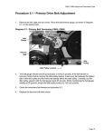
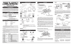
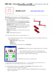
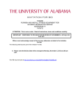
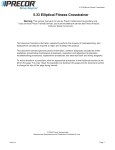
C842i, C846i Upright and Recumbent Cycle
Procedure 7.1 - Removing or Replacing One or Both Covers
1.
Remove four screws from the and left side of the top cover.
2.
Remove two screws from the rear of the cover and two screws from the bottom of the left
and right covers. Remove the left and right cover. Grasp the top cover and move it sideways
away from the front column. Slide the top cover forward and off.
3.
When maintenance procedures are complete, set the top cover in place. Gently spread the
the two projecting legs at the rear of the cover and slide the legs under the seat rail. Take
care that you do not snag the lower PCA wiring with the top cover legs.
4.
Hand start the two front bolts third from the front top cover mounting bolts on both sides of
the cover. Only start them a few threads, just enough so that they are securely in place.
5.
Slide the top edge of the right side cover under the top cover and hand start the two
remaining top bolts and the two bottom bolts.
6.
Slide the top edge of the left side cover under the top cover and hand start the two
remaining top bolts and the two bottom bolts. Hand start the two rear cover bolts.
7.
Securely tighten all fourteen cover bolts.
Page 29
C842i, C846i Upright and Recumbent Cycle
Procedure 7.2 - Replacing a Crankarm
1.
Grasp the pedal spindle with an open end wrench where it threads into the crankarm. The
right hand pedal has normal threads and the left hand pedal has reverse threads. The Left
hand pedal must be turned clockwise to loosen and counter-clockwise to tighten. Un-thread
the pedal from the crankarm.
2.
Remove the crankarm mounting bolt from the crankarm to be replaced. See Diagram 7.1.
Diagram 7.1 - Crankarm Replacement
Mounting
Bolt
Crankarm
3.
Remove the crankarm. It may be necessary to use a gear puller or pitman arm puller to
remove the crankarm.
4.
Position the replacement crankarm the input shaft. Ensure that the crankarm alignment pin
engages in its mating hole in the primary pulley. Thread and hand tighten the crankarm
mounting bolt into the input pulley shaft. Torque it to 420 in/lbs (35 foot pounds).
5.
Hand thread the pedals into the crankarms. Remember, the left hand pedal is reverse
threaded.
6.
Torque the pedals to 150 inch pounds (12.5 foot pounds).
7.
Set the bicycle at it’s highest resistance setting and use the bicycle for a minimum of 3
minutes. Re-torque the crank arm mounting bolt to 420 in/lbs (35 foot pounds). Use the
bicycle for at least ten minutes, then re-torque the crankarm bolt to 420 in/lbs (35 foot
pounds).
Page 30
C842i, C846i Upright and Recumbent Cycle
Procedure 7.3 - Replacing the Seat or Seat Post
(Upright Cycle)
1.
Loosen the seat mounting nut with a box or open end wrench. Lift the seat upward and off of
the seat post. If you are not replacing the seat post, skip to step 4.
2.
Pull outward on the seat adjustment knob and lift the seat post out of the cycle’s frame.
Diagram 7.2 - Seat, Upright Cycle
Seat
Seat Post
Seat Adjustment Knob
3.
Pull the seat adjustment knob outward, slide the replacement seat post into place in the
cycle’s frame. Release the seat adjustment and move the seat post until the seat post
locking mechanism snaps into place and locks the seat post into position.
4.
Set the replacement seat into place on the seat post and securely tighten seat mounting nut.
5.
Test the seat and seat post to ensure they are securely tightened.
Page 31
C842i, C846i Upright and Recumbent Cycle
Procedure 7.4 - Replacing All or Part of a Seat Carriage
Assembly (Recumbent Cycle)
1.
There is a hand held heart rate cable the connects the seat carriage to the seat rail. Care
must be taken when removing the seat carriage to avoid damaging the hand held heart rate
cable.
2.
Move the seat to its most forward position. Remove the seat accessory tray by carefully
spreading the tabs and sliding the tray off of the acorn nuts.
Diagram 7.3 - Seat Rail
End Cap
Seat Stop
Seat Rail
3.
Loosen but do not remove the two screws retaining the end cap. Remove the end cap.
Remove both seat stops, one each side.
4.
Locate the plate that covers the hand held heart rate cable, on the seat rail near the rear of
the seat. Remove the plate. The cable may be stuck to the plate with double sided tape.
5.
Remove the two screws that fasten the plate to the seat rail. Extract enough cable from the
seat rail to access the cable connectors. Carefully, pull all excess cable out from under the
seat, so that it is looped behind the seat. See Diagram 7.4. Disconnect the two cables.
Page 32
C842i, C846i Upright and Recumbent Cycle
Diagram 7.4 - Hand Held Heart Rate Cable
Seat
Cable
Seat Rail
Cable
6.
Slide the seat rail cable back into the access hole. The seat carriage must travel over this
cable, so it must be below the surface of the seat rail. Release the seat lever, hold the cable
attached to the seat straight back from the seat as you slide the entire seat and seat
carriage off of the rear of the seat rail. See Diagram 7.5.
Diagram 7.5 - Hand Held Heart Rate Cable
7.
Remove the plate that covers the hand held heart rate cable on the bottom of the seat. See
Diagram 7.6. The cable may be stuck to the plate with double sided tape.
Page 33
C842i, C846i Upright and Recumbent Cycle
Diagram 7.6 - Seat Bottom
Cable
Cover
8.
Disconnect the external hand held heart rate cable from the internal hand held heart rate
cable.
9.
If only the external cable is being replaced, skip to step 14. If the internal cable is being
replaced continue with step 10.
10. Remove the screws retaining the hand held heart rate contact plates from both the left and
right seat handlebars. Disconnect the cable from all four hand held heart rate contact plates.
Draw the internal cable out of the bottom of the seat.
11. Feed the replacement internal hand held heart rate cable into the seat. The cable with the
blue tape will feed into the right handlebar and the cable with the black tape will feed into the
left handlebar. See Diagram 7.7.
Diagram 7.7 - Internal Hand Held Heart Rate Cable
Black Tape
Blue Tape
Page 34
C842i, C846i Upright and Recumbent Cycle
12. Feed the wire ends out of the handlebars so that the black wire comes out of the top of the
handlebars and the red wire comes out of the bottom of the handlebar.
13. Connect the black wires to the hand held heart rate top contact plates and the red wires to
the bottom contact plates. Fasten the hand held heart rate contact plates with the screws
removed in step 10.
14. Connect the existing or replacement external hand held heart rate cable to the internal hand
held heart rate cable. Feed the cable connectors into seat.
15. Replace the cover plate removed in step 22. Before replace the cover plate mounting
screws, be sure that the cable is centered on the cover plate so that the cover plate
mounting screws will not damage the external hand held heart rate cable.
16. With the seat cable extended to the rear of the seat, slide the seat onto the seat rail to its
most forward position.
17. Extract the hand held heart rate cable from the seat rail and connect it to the hand held heart
rate seat cable. The cables should again look as they did in Diagram 7.4.
18. Slide the cable connectors back into the seat rail and replace the plate removed in step 18.
Stick the plate to the double sided tape on the cable and fasten the plate to the seat rail with
the screws previously removed.
19. Carefully feed all of the excess cable back under the seat.
20. Replace both seat stops. Replace the end cap.
21. If necessary, adjust the seat wheels per Procedure 5.3.
Page 35
C842i, C846i Upright and Recumbent Cycle
Procedure 7.5 - Replacing the Column
1.
Remove the display housing per Procedure 7.12.
2.
While supporting the column, remove the two large bolts that fastens the lower portion of the
column to the main frame. Carefully move the column away from the bike frame, taking care
not to damage the cables shown in Diagram 6.2. Lay the column on the floor near the front
of the bike.
3.
Extract both cables from the column.
4.
Set the replacement column on the floor near the front of the bike. Feed both cables
removed in step 3 into the replacement column.
5.
Attach the rubber boot, from the original column, to the bottom of the replacement column.
Carefully feed the cables into the column and the main frame as you move the column into
its mounting position.
6.
Hand start both of the column mounting bolts removed in step 2. Securely tighten both
column mounting bolts.
7.
Reconnect the interconnect cable to the J1 connector on the upper PCA. Connect the hand
held heart rate cable to J4 of the hand held heart rate PCA.
8.
Set the display housing at it’s mounting position on the display backing plate. Replace and
tighten display housing mounting screws.
Page 36
C842i, C846i Upright and Recumbent Cycle
Procedure 7.6 - Replacing the Upper or Lower Interconnect
Cable or Heart Rate Cable
1.
Remove the display housing per Procedure 7.12. Disconnect the interconnect cable from J1
of the upper PCA or the heart rate cable from J4 of the hand held heart rate PCA.
2.
Connect the replacement interconnect cable to the J1 connector on the upper PCA or the
replacement hand held heart rate cable to J4 of the hand held heart rate PCA.
3.
Set the display housing at it’s mounting position on the display backing plate. Replace and
tighten display housing mounting screws.
4.
If you are replacing only the upper interconnect or heart rate cable, skip to step 10.
5.
On recumbent units, disconnect the lower heart rate cable from the upper heart rate cable.
Slide the seat to its most forward position. Remove the plate covering the heart rate cable.
Disconnect the cable in the frame from the cable to the seat. Pull the cable out of the frame
from the front.
6.
Feed the replacement cable into the frame from behind the seat. Pull the cable out of the
front of the frame and connect it to the upper heart rate cable.
7.
Connect the other end of the cable to the seat cable. Feed all excess seat cable under the
seat. Replace the cable plate removed in step 5.
8.
Disconnect the lower interconnect cable from the upper interconnect cable. Disconnect the
lower interconnect cable from the J2 connector of the lower PCA. Remove the cable from
the frame cable clips.
9.
Connect the replacement lower interconnect cable to J2 of the lower PCA. Feed it through
the frame cable clips and connect the other end to the upper interconnect cable.
10. While supporting the column, remove the two large bolts that fastens the lower portion of the
column to the main frame. Carefully move the column away from the bike frame, taking care
not to damage the cables shown in Diagram 6.1. Lay the column on the floor near the front
of the bike.
11. Draw the cable being replaced out of the bottom of the column. Disconnect the cable being
replaced from the lower cable. Feed the replacement cable into the top of the column. When
it appears at lower access hole in the column, draw it out and connect it to its mating lower
cable.
12. Verify that the rubber boot is still on the bottom of the column. Carefully feed the cables into
the column and the main frame as you move the column into its mounting position.
13. Hand start both of the column mounting bolts removed in step 10. Securely tighten both
column mounting bolts
Page 37
C842i, C846i Upright and Recumbent Cycle
Procedure 7.7 - Replacing the Battery
1.
If the cycle is equipped with an external power adapter, disconnect the power adapter from
the cycle.
2.
Remove left side cover.
3.
Disconnect the positive (red) and negative (black) wires from the battery. Remove the two
screws that fasten the battery bracket to the frame. Remove the battery and battery bracket.
4.
PLace the battery bracket on the replacement battery and set them in their mounting
position with the positive terminal (red dot) to the left side of the bike. See Diagram 7.16.
Diagram 7.8 - Battery, C842i, C846i
Battery
Bracket
Red Wire
Red Dot
Battery
5.
Fasten the battery bracket with battery to the frame with the screws removed in step 13.
6.
Connect the red wire to the battery’s positive terminal (red dot) and the black wire to the
battery’s negative terminal.
Page 38
C842i, C846i Upright and Recumbent Cycle
Procedure 7.8 - Replacing the Lower PCA
1.
Disconnect the optional external power adapter, if equipped.
2.
Remove the left, right and top covers.
3.
Disconnect the red wire from the battery. Disconnect all of the wires from the lower PCA.
4.
Remove the four lower PCA mounting screws. Remove the lower PCA.
5.
Set the replacement lower PCA at its mounting position, with terminal M1 facing the front of
the bike. See Diagram 6.2.
6.
Refer to Diagram 6.2 and replace the lower PCA wiring as follows. Connect the wires from
the external power jack to connector J4 on the lower PCA. Connect the two red wires from
the eddy current magnet to terminals M1 and M2 of the lower PCA (it does not matter which
red wire goes on terminal M1 or M2). Connect the red wire from the generator to terminal
M3, connect the black wire from the generator to terminal M4 and the white wire from the
generator to terminal M5. Connect the interconnect cable to connector J2 on the lower PCA.
Connect the black wire from the battery to terminal M7 and the red wire to terminal M6 of the
lower PCA.
7.
Reconnect the red wire, removed in step 3, to the positive terminal (red dot) of the battery.
8.
Reconnect the external power adapter, if equipped.
Page 39
C842i, C846i Upright and Recumbent Cycle
Procedure 7.9 - Replacing the Display Housing
or Upper PCA
1.
Remove the screws that retain the display, lift the display and disconnect the interconnect
cable from the J5 connector and the heart rate cable from the J1 connector.
2.
Disconnect the keypad cable from the J2 connector.
3.
Remove the screws the retain the upper PCA to the display. Remove the upper PCA.
4.
Many PCA’s are furnished without software, If your PCA does not have an IC chip installed
in the U6 socket, remove the U6 IC chip from the existing PCA (using a IC extractor and
anti-static protection) and install it on the replacement PCA.
5.
Set the replacement PCA in its mounting position and fasten it with the screws removed in
step 1.
6.
Connect the keypad cable to the J2 connector.
7.
Hold the display near its mounting position and connect the interconnect cable to the J5
connector and the heart rate cable to the J1 connector.
8.
Set the display in its mounting position and fasten it with the screws removed in step 14.
Page 40
C842i, C846i Upright and Recumbent Cycle
Procedure 7.10 - Replacing the Primary Drive Belt
1.
Remove the right side cover.
2.
Loosen but do not remove the locknut retaining the idler pulley. See Diagram 7.9. This will
remove tension from the primary belt.
Diagram 7.9 - Primary Drive Belt, C842i, C846i
Primary
Pulley
Primary
Belt
Pulley
Cover
Secondary
Axle
Idler Pulley
3.
Remove the primary belt. Route the replacement primary belt around the primary pulley,
over the idler pulley and around the secondary axle as shown in Diagram 7.9.
4.
Tension the primary belt per Procedure 5.1.
5.
Replace the right side cover.
Page 41
C842i, C846i Upright and Recumbent Cycle
Procedure 7.11 - Replacing the Secondary Drive Belt
1.
Remove the left side cover.
2.
Loosen the jam nuts on the secondary belt tension adjustment bolt. Loosen the adjustment
bolt to remove tension from the secondary belt. See Diagram 7.10. remove the secondary
belt.
Diagram 7.10 - Secondary Drive Belt, C842i, C846i
Secondary
Belt
Secondary
Pulley
Generator
Pulley
Adjustment
Bolt
Jam Nuts
3.
Route the replacement secondary belt over the secondary pulley and generator pulley as
shown in Diagram 7.10.
4.
Tension the secondary belt per Procedure 5.2.
5.
Replace the left side cover.
Page 42
C842i, C846i Upright and Recumbent Cycle
Procedure 7.12 - Replacing the Primary Pulley or Primary
Bearings
1.
Remove the left, right and top covers.
2.
Remove the left and right crankarms per Procedure 7.2. Slide the left pulley cover off of the
primary pulley axle.
3.
Remove the five bolts retaining the right pulley cover. See Diagram 7.9. Remove the right
pulley cover.
4.
Loosen the idler pulley locknut and release tension from the primary belt.
5.
There are two small screws retaining the left and right hand primary pulley bearings in the
frame. The screws retaining the left hand bearing are easily visible. The primary pulley has
holes in it that will align with and provide access to the right hand bearing retaining screws.
Remove all four bearing retaining screws.
6.
Remove the large cease nut from the left side of primary pulley shaft. Slide the primary
pulley out of the frame. The left hand bearing is in the frame bearing pocket, the right side
bearing is part of the primary pulley assembly.
7.
If the bearings are being replaced, slide the left hand bearing out of the frame pulley pocket.
Slide the replacement bearing into the left hand frame pocket and fasten it with two of the
bearing retaining screws removed in step 5.
8.
Slide the replacement primary pulley assembly into place in the frame. Align the holes in the
primary pulley with the bearing retaining holes. Fasten the right hand bearing with the
remaining two screws removed in step 5.
9.
Thread the large cease nut, removed in step 6 onto the primary pulley shaft and tighten. Do
not over tighten the cease nut, the primary pulley must turn freely without any wobble or
lateral movement.
10. Set the right hand pulley cover in its mounting position and retain it with screws removed in
step 3. Torque the screws to 50 inch pounds. Slide the left pulley cover onto the primary
shaft.
11. Replace both crankarms per Procedure 7.2.
12. Tension the primary belt per Procedure 5.1.
13. Replace the left, right and top covers.
Page 43
C842i, C846i Upright and Recumbent Cycle
Procedure 7.13 - Replacing the Secondary Pulley,
Intermediate Pulley or Secondary Bearings
1.
Remove the left, right and top covers.
2.
If only the secondary pulley is being replaced (the secondary pulley assembly contains the
clutch bearing), skip this step and continue with step 16. Loosen the idler pulley locknut and
release tension from the primary belt.
3.
Loosen the secondary belt adjustment bolt and remove tension from the secondary belt.
4.
Remove the retaining ring from the left side of the secondary pulley shaft.
5.
Slide the large thrust washer off of the secondary pulley shaft. Slide the secondary pulley off
of the secondary pulley shaft. If only the secondary pulley is being replaced, skip to step 13.
6.
Slide the remaining thrust washer off of the secondary pulley shaft and remove the second
retaining ring from the secondary pulley shaft.
7.
Insert an allen wrench into the left end of the secondary pulley shaft and remove the
secondary axle with a 20030-119 secondary sheave tool and a 1/2 inch drive socket
wrench. See Diagram 7.9.
8.
Remove the large retaining from the right hand side bearing pocket and slide the secondary
shaft out of the frame. There is now a loose wave washer still inside the frame bearing
pocket. Remove and retain the wave washer.
9.
The left side bearing, secondary axle or secondary shaft assembly may now be replaced as
required.
10. Slide the wave washer, from step 8 onto the longer end of the secondary shaft. Slide the
longer end of the secondary shaft into the left side bearing. Replace the large retaining ring,
removed in step 21, into the right hand side bearing pocket.
11. Insert an allen wrench into the left end of the secondary pulley shaft, thread the secondary
axle onto the secondary axle and tighten with a 20030-119 secondary sheave tool and a
1/2 inch drive socket wrench.
12. Replace the inside retaining ring, removed in step 6, onto the secondary pulley shaft. Slide
one of the thrust washers onto the secondary pulley shaft.
13. Slide the replacement secondary pulley onto the secondary pulley shaft.
14. Slide the remaining thrust washer onto the secondary pulley shaft. Replace the outside
retaining ring, removed in step 14
Page 44
C842i, C846i Upright and Recumbent Cycle
15. Route the secondary belt over the secondary pulley and the generator pulley. Tension the
secondary belt per Procedure 5.2.
16. If necessary, route the primary belt around the primary pulley, over the idler pulley and
around the secondary axle as shown in Diagram 7.9. Tension the primary belt per
Procedure 5.1.
17. Replace the left, right and top covers.
Page 45
C842i, C846i Upright and Recumbent Cycle
Procedure 7.14 - Replacing the Idler Pulley
1.
Remove the right hand cover.
2.
Loosen the idler pulley locknut to remove tension from the primary belt. Then remove the
idler pulley locknut. Remove the idler pulley from its mounting bolt.
3.
Slide the replacement idler pulley onto its mounting bolt and hand start the idler pulley
locknut.
4.
Tension the primary belt per Procedure 5.1.
5.
Replace the right hand cover.
Page 46
C842i, C846i Upright and Recumbent Cycle
Procedure 7.15 - Replacing the PROM
Anti-static kits (part number 20024-101) can be ordered from Precor.
1.
The PROM and the associated printed circuit assembly (PCA) are static sensitive. Antistatic devices must be used and all anti-static precautions must be followed during this
procedure.
2.
Remove the printed circuit assembly per its associated procedure.
3.
Currently we are using two styles of IC software packages. they are a 28 pin dual in line
package (DIP28) and a forty-four pin square package (PLCC44). Each of these packages
should be removed with a proper IC removal tool (see the illustrators below)
PLCC44 removal tool
DIP28 removal tool
4.
The IC’s may inserted into their socket by hand by carefully aligning the notch on the IC with
the notch on the IC socket and carefully pressing the IC into its socket. See the illustrations
below for the alignment notches. Care must be taken that the IC legs on a DIP28 are all
aligned in the socket to prevent the legs from bending when inserted. The PLCC44 IC must
be carefully aligned squarely in its socket or it will not insert. Do not force the IC into its,
socket. If it does not insert easily, remove the it and re-align it in its socket.
DIP28
Notch
Notch
Notch
PLCC44
Notch
Page 47
C842i, C846i Upright and Recumbent Cycle
Procedure 7.16 - Generator Replacement
1.
Remove the left and right side covers.
2.
Remove the positive (red) wire from the battery.
3.
Remove all of the wiring from the lower PCA.
4.
Loosen the secondary belt adjustment belt to remove tension from the secondary belt.
5.
Remove the four generator mounting bolts. See Diagram 7.11
Diagram 7.11 - Generator Mounting C842i, C846i
Lower PCA
Generator
Mounting
Bolt
6.
Remove the generator with the lower PCA from the bike.
7.
Using anti-static protection, remove the four screws that fasten the lower PCA onto its
mounting bracket.
8.
Remove the four screws that fasten the lower PCA mounting bracket to the generator.
9.
Mount the lower PCA mounting bracket on the replacement generator with the screws
removed in step 8.
10. Mount the lower PCA on the mounting bracket with the screws removed in step 7.
Page 48
C842i, C846i Upright and Recumbent Cycle
11. Refer to Diagram 6.2 and replace the lower PCA wiring as follows. Connect the wires from
the external power jack to connector J4 on the lower PCA. Connect the two red wires from
the eddy current magnet to terminals M1 and M2 of the lower PCA (it does not matter which
red wire goes on terminal M1 or M2). Connect the red wire from the generator to terminal
M3, connect the black wire from the generator to terminal M4 and the white wire from the
generator to terminal M5. Connect the interconnect cable to connector J2 on the lower PCA.
Connect the black wire from the battery to terminal M7 and the red wire to terminal M6 of the
lower PCA.
12. Reconnect the red battery wire to the positive terminal of the battery.
13. Replace the left and right side covers
Page 49
C842i, C846i Upright and Recumbent Cycle
Procedure 7.17 - Primary Axle or Bearing Replacement
1.
Remove the left and right side covers.
2.
Remove both the left and right hand pedals. Refer to Procedure 7.2.
3.
Remove the screws that retain both the left and right hand crankarm covers. Remove both
of the crankarm covers. See Diagram 7.12.
Diagram 7.12 - Crankarm Covers
Crankarm
Cover
Retaining
Screw
32 mm Nut
4.
Remove the 32 mm nut from the left side of the primary axle. See Diagram 7.12.
5.
Remove the two screws retaining the outer bearing race of the left hand bearing. See
Diagram 7.13. The right hand bearing has two retaining screws like the screws just removed
from the left hand bearing. It is necessary to rotate the primary pulley until the access hole in
the primary pulley aligns with the retaining screw. See Diagram 7.33. Remove both retaining
screws from the right hand bearing.
6.
Loosen but do not remove the locknut retaining the idler pulley. See Diagram 7.23. This will
remove tension from the primary belt. Remove the primary belt.
7.
The right hand bearing is equipped with a integral 32 mm nut. Remove the left hand bearing
by threading the 32 mm bearing nut off of the primary axle. See Diagram 7.14. Use a rubber
mallet to tap on the left end of the primary axle to remove the primary axle from the frame. If
necessary remove the left hand bearing from its bearing pocket.
Page 50
C842i, C846i Upright and Recumbent Cycle
Diagram 7.13 - Outer Bearing Race Retaining Screws
32 mm
Bearing Nut
Retaining
Screw
Primary
Axle
8.
Carefully, clean both bearing pockets with a clean dry cloth. You may apply a thin coat of
lubricant to the bearing pockets to facilitate re-installation of the bearings.
9.
If the left hand bearing requires replacement, replace it with Precor part number 45441-103.
The right hand bearing is part of the primary pulley assembly. If the right hand bearing
requires replacement, replace Precor part number 45439-102 primary pulley assembly. See
Diagram 7.14.
Diagram 7.14 - Primary Pulley Assembly
Access Hole
10. Slide the primary pulley assembly into the frame from the right hand side. Slide the left hand
bearing over the primary axle and hand thread the bearing nut onto the primary axle. When
you are sure the bearing nut is properly threading onto the primary axle, not crossthreading, torque the bearing nut to 60 inch-pounds.
11. Replace and tighten the right hand and left hand outer bearing race retaining screws
removed in step 5.
Page 51
C842i, C846i Upright and Recumbent Cycle
12. Thread the 32 mm nut, removed in step 4, onto the left side of the primary axle and torque it
60 inch-pounds.
13. Route the primary belt around the primary pulley, over the idler pulley and around the
secondary axle as shown in Diagram 7.9.
14. Tension the primary belt per Procedure 5.1.
15. Replace the crankarm covers and fasten them with the hardware removed in step 3.
16. Replace both the left and right hand pedals. Refer to Procedure 7.2.
17. Replace both covers and thoroughly test the bicycle per Section 4
Page 52