1
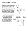
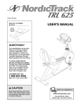
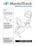
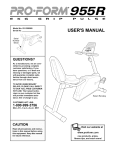
C842i, C846i Upright and Recumbent Cycle
Procedure 5.1 - Primary Drive Belt Adjustment
1.
Remove the left, right and top covers. Place the belt tension gauge, as shown in Diagram
5.1, on the primary belt.
Diagram 5.1 - Primary Belt Tensioning C842i, C846i
Belt
Gauge
Primary
Belt
Idler
Pulley
Idler Pulley Locknut
2.
The belt gauge should read 95 pounds plus or minus 5 pounds. If the belt tension is
incorrect, loosen but do remove the idler pulley locknut. Insert a pry bar between the bottom
side of the idler pulley and the frame tab directly below the idler pulley. Carefully, pry the
idler pulley upward until the belt gauge reads 95 pounds. While maintaining the belt gauge
reading at 95 pounds, torque the idler pulley locknut to 120 inch pounds.
3.
Check the secondary belt tension per procedure 5.2.
4.
Replace the top and both side covers.
Page 15
C842i, C846i Upright and Recumbent Cycle
Procedure 5.2 - Secondary Drive Belt Adjustment
1.
Remove both side covers and the top cover. Place the belt tension gauge, as shown in Diagram 5.2, on the secondary belt.
Diagram 5.2 - Secondary Belt Tensioning C842i, C846i
Belt
Gauge
Generator
Secondary
Belt
2.
The belt gauge should read 90 pounds plus or minus 5 pounds.
3.
The secondary belt tension is set by adjusting the position of the generator. Loosen but do
not remove the four generator mounting bolts. Loose the jam nut on the belt tension
adjustment bolt mounted on the generator (see Diagram X). Adjust the belt tension bolt until
the belt gauge reads 90 pounds.
4.
Tighten the belt adjustment bolt’s jam nut. Torque the four generator mounting bolts to 150
inch pounds.
Page 16
C842i, C846i Upright and Recumbent Cycle
Procedure 5.3 - Recumbent Seat Adjustment
1.
Perform this procedure if the front to rear movement of the seat is too tight or there is
excessive side to side seat wobble.
2.
Loosen but do not remove the four mounting screws on the left and right seat adjustment
plates. See Diagram 5.3
Diagram 5.3 - Recumbent Seat Adjustment (All versions)
Adjustment
Plate
Seat
Carriage
Mounting
Screw
Adjustment
Wrench
3.
Insert an allen bit into the adjustment hole in one of the seat adjustment plates. Rotate the
adjustment plate counterclockwise to loosen or clockwise to tighten the seat. Perform half of
the adjustment using the right hand adjustment plate and half of the adjustment using the
left hand adjustment plate.
4.
Apply a minimum of pressure to the adjustment wrench when tightening the seat
adjustment. Apply only enough pressure to rotate the adjustment plate fully clockwise.
5.
When the seat is properly adjusted, the angle of rotation of both adjustment plates should
be approximately the same. The seat should not wobble side to side and should move
forward and backward easily.
6.
Torque the four seat adjustment plate mounting screws to 120 in/lb.
Page 17