1
TS-870S modification
7.
8.
9.
10.
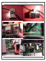
positioned as depicted by picture 11. Picture 12 shows
the circuit by side.
Solder the switching unit power supply (12V) to the same
RF UNIT board with a shielded cable as shown in picture
13 and note that the ground connection is screwed to the
print.
Locate LCD ASSY board B38-0736-05 up left of picture
14 near the flat cable.
Solder the DIM signal (the signal used to switch the relay)
to a shielded cable and ground the shield to the print by
the same screw as shown in picture 15.
Remount the shielding board and the lower cover.
Figure 5
Figure 7
Figure 6
nd
2
IF SSB/CW filter modification
1. Remove the lower cover.
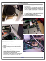
2. Locate RF UNIT board X44-3210-00 (A/9) as depicted by
picture 7.
3. Remove shielding board, unplug cables and remove
screws.
4. Substitute filter CF452 with 2 pieces of coaxial cable like
RG174 as shown in picture 8.
5. Remount the board and plug all the cables.
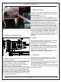
6. Solder the filter input/output of the circuit shown in the
Figure 8
following chapter to the coaxial cable as shown in
pictures 9 or 10. They show two different
implementations. Please note there is not much place in
the rig. The filters are placed one by the other, and
1/1/2012
3/6