1
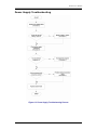
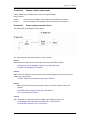
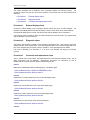
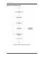
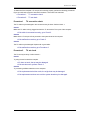
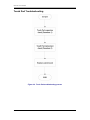
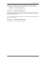
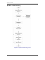
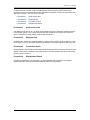
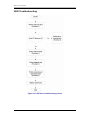
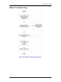
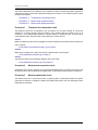
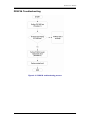
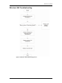
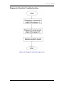
Chapter 6 Testing and Troubleshooting GL31 Service Manual Testing and Troubleshooting The purpose of this chapter is to provide a systematic method of isolating problems you may have with the HGL3031 series Notebook Computer. We assume that you have a basic understanding of DOS-based computer systems as well as knowledge of standard trouble-shooting procedures. This manual is written under the assumption that the problems are indeed related with Notebook itself. The improper usage and application software problems are excluded in this chapter. The system BIOS Beep Code is an integrated unit to detect some errors in the system board. This beep code will give immediate identification of certain system board problems. If the troubleshooting procedure is followed step by step, it can efficiently isolate the problem and the problem can be solved easily. PERFORM VISUAL INSPECTION Check the following: Power cords are properly connected and secured Power supply is adequate for operation There are no obvious shorts or opens There are no obviously burned or heated components All components appear normal Troubleshooting Flowchart Use the flowchart in Figure 6-1 as a guide for determining which troubleshooting procedures to execute. Before going through the flowchart steps, verify the following: Ask the user if a password is registered and, if it is, ask him or her to enter the password. Verify with the customer that Windows XP SP2 is installed on the hard disk. Operating systems that were not preinstalled by Compal can cause the computer to malfunction. Make sure all optional equipment is removed from the computer. Make sure the floppy disk drive is empty. 6-1 GL31 Service Manual Figure 6-1 Troubleshooting flowchart (1/2) 6-2 GL31 Service Manual Figure 6-1 Troubleshooting flowchart (2/2) 6-3 GL31 Service Manual If the diagnostics program cannot detect an error, the problem may be intermittent. The test program should be executed several times to isolate the problem. When a problem has been located, perform the appropriate troubleshooting procedures as follows: If an error is detected by the main battery test, perform the Power Supply Troubleshooting procedures in Section 6-2. If an error is detected by the display test, perform the Display Troubleshooting procedures in Section 6-3. If an error is detected by the floppy disk test, perform the FDD Troubleshooting procedures in Section 6-4. If an error is detected by the keyboard test, perform the Keyboard Troubleshooting procedures in Section 6-5. If an error is detected by the printer (parallel) port test, perform the Printer Port Troubleshooting procedures in Section 6-8. If an error is detected by the CD-ROM/DVD-ROM test, perform the DVD-ROM and CD-RW/DVD-ROM Troubleshooting Procedures in Section 6-11. If an error is detected by the Modem test, perform the Modem Troubleshooting Procedures in Section 6-12 or the LAN Troubleshooting Procedures in Section 2.11. If an error is detected by the Sound test, perform the Sound Troubleshooting Procedures in Section 2.12. Other problems that are not covered by the diagnostics program may be discovered by a user. If an error is detected when using an external USB device, perform the External USB Devices Troubleshooting procedures in Section 6-6. If an error is detected when using the TV-out connection, perform the TV-Out Failure Troubleshooting procedures in Section 6-7. If an error is detected when using the touch pad, perform the Touch Pad Troubleshooting procedures in Section 6-9. If an error is detected when using the speakers, perform the Speaker Troubleshooting procedures in Section 6-10. If an error is detected when using the CD/DVD drive, perform the CD-ROM/DVD Drive Troubleshooting procedures in Section 6-11. If an error is detected when using the modem, perform the Modem Troubleshooting procedures in Section 6-12. If an error is detected when using the PCMCIA unit, perform the PCMCIA Troubleshooting procedures in Section 6-13. 6-4 GL31 Service Manual Power Supply Troubleshooting Figure 6-2 Power Supply Troubleshooting Process 6-5 GL31 Service Manual The power supply controls many functions and components. To determine if the power supply is functioning properly, start with Procedure 1 and continue with the other Procedures as instructed. The flowchart in Figure 6-2 gives a summary of the process. The procedures described in this section are: Procedure 1: Power status check Procedure 2: Adaptor / battery replacement Procedure 3: Power supply connection check Procedure 4: Diagnostic check Procedure 5: Internal connection check Procedure 1 Power Status Check The following LEDs indicate the power supply status: Battery LED The power supply controller displays the power supply status through the Battery and the POWER LEDs as listed in the tables below. Table 2-1 Battery LED Battery State LED colors Charging Green, solid on Amber, solid on color off Discharging Amber, blinking LED on for 1 second every 4 seconds Amber, blinking (LED on 1 second every 2 seconds) Amber solid on Definition Battery charging with AC . Battery fully charged by AC Battery abnormal: stop charging with AC (Bad cell/ Overheated) Battery within low state: 12 minutes remaining Battery within critical low state: 3 minutes remaining. The system is protected and cannot be re-powered on without the AC power connected. Battery not in low or critical low state; in discharging state Table 2-2 POWER LED Power supply status System Power On (LED is solid Green). System Suspended System Power Off. POWER LED Green Solid on off Off To check the power supply status, install a battery pack and connect an AC adaptor to the DC-IN port on the computer and to a power supply. If the Battery LED are not lit, go to Procedure 2 6-6 GL31 Service Manual Procedure 2 Adaptor / battery replacement A faulty adaptor may not supply power or may not charge the battery. Perform Check 1. Check 1 Connect a new AC adaptor. If the problem is not resolved, go to Check 2. Check 2 Insert a new battery. If the problem is still not resolved, go to Procedure 3. Procedure 3 Power supply connection check The power supply wiring diagram is shown below: Any of the connectors may be disconnected. Perform Check 1. Check 1 Disconnect the AC power cord from wall outlet. Check the power cable for breaks. If the power cord is damaged, connect a new AC power cord. If there is no damage, go to Check 2. Check 2 Make sure the AC adaptor cord and AC power cord are firmly plugged into the DC-IN socket, AC adaptor inlet and wall outlet. If these cables are connected correctly, go to Check 3. Check 3 Make sure that the DC-IN input port socket is firmly secured to the system board of the computer. If the DC-IN input socket is loose, go to Procedure 5. If it is not loose, go to Check 4. Check 4 Use a multi-meter to make sure that the AC adaptor output voltage is close to 19 V. If the output is several percent lower than 19 V, go to Check 5. If the output is close to 19 V, go to Check 6. 6-7 GL31 Service Manual Check 5 Connect a new AC adaptor or AC power cord. If the battery LED does not light, go to Check 6. Check 6 Make sure the battery pack is installed in the computer correctly. If the battery is properly installed and the battery LED still does not light, go to Procedure 4. Procedure 4 Diagnostic check The power supply may not charge the battery pack. Perform the following procedures: Reinstall the battery pack. Attach the AC adaptor and turn on the power. If you cannot turn on the power, go to Procedure 5. Run the Diagnostic test following the procedures described Tests and Diagnostics. If no problem is detected, the battery is functioning normally. Procedure 5 Replacement check The system board may be disconnected or damaged. Disassemble the computer following the steps described Replacement Procedures. Check the connection between the AC adaptor and the system board. After checking the connection, perform Check 1: Check 1 Use a multi-meter to make sure that the fuses on the system board are not blown. If a fuse is not blown, go to Check 2. If a fuse is blown, go to Check 3. Check 2 Make sure that the battery cable is firmly connected to the system board. If it is connected firmly, go to Check 3. Check 3 The system board may be damaged. Replace it with a new one following the instructions in Chapter 4. 6-8 GL31 Service Manual Display Troubleshooting Figure 6-3 Display troubleshooting process 6-9 GL31 Service Manual This section describes how to determine if the computer’s display is functioning properly. The process is outlined in Figure 6-3. Start with Procedure 1 and continue with the other procedures as instructed. Procedure 1: Procedure 2: Procedure 3: Procedure 1 External display check Diagnostic check Connector and replacement check External display check Connect an external display to the computer’s external monitor port, then boot the computer. The computer automatically detects the external display. Press Fn+F5 to switch to the external display. If the external display works correctly, the internal LCD may be damaged. Go to Procedure 3. If the external monitor appears to have the same problem as the internal monitor, the system board may be damaged. Go to Procedure 2. Procedure 2 Diagnostic check The Display Test program is stored on the computer’s Diagnostics disk. This program checks the display controller on the system board. Insert the Diagnostics disk in the computer’s floppy disk drive, turn on the computer and run the test. Refer to Chapter 3, Tests and Diagnostics for details. If an error is detected, go to Procedure 3. If an error is not detected, the display is functioning properly. Procedure 3 Connector and replacement check The FL inverter board, LCD module, and system board are connected to the display circuits. Any of these components may be damaged. Replacement Procedures, for instructions on how to disassemble the computer and then perform the following checks: Check 1 Make sure the DDRRAM module is seated properly. Test display again. If the problem still exits, replace the DDRRAM module. If the problem still exists, perform check 2. Check 2 Replace the FL inverter board with a new one and test display again. If the problem still exists, perform Check 3. Check 3 Replace the LCD module with a new one and test display again. If the problem still exists, perform Check 4. Check 4 Replace the LCD/FL cable with a new one and test display again. If the problem still exists, perform Check 5. Check 5 Replace the CPU with another of the same specifications. If the problem still exists, perform Check 6. Check 6 6-10 GL31 Service Manual The system board may be damaged. Replace it with a new one. 6-11 GL31 Service Manual Keyboard Troubleshooting Figure 6-5 Keyboard troubleshooting process 6-12 GL31 Service Manual To determine if the computer’s keyboard is functioning properly, perform the following procedures. Figure 6-5 outlines the process. Start with Procedure 1 and continue with the other procedures as instructed. Procedure 1: External keyboard check Procedure 2: Diagnostic check Procedure 3: Connector and replacement check Procedure 1 External keyboard check Connect a USB keyboard to one of the computer’s keyboard/mouse ports, then boot the computer. The computer automatically detects the external keyboard. If the external keyboard works correctly, the internal keyboard or its connections may be faulty. Go to Procedure 2. If the external keyboard appears to have the same problem as the internal keyboard, the system board may be damaged. Procedure 2 Diagnostic test Run the Diagnostic Program, which will automatically execute the Keyboard Test. Refer to Chapter 3, Tests and Diagnostics for more information on how to run the program. If an error is located, go to Procedure 3. If an error does not occur, the keyboard is functioning properly. Procedure 3 Connector and replacement check The keyboard and/or system board may be disconnected or damaged. Replacement Procedures and perform the following checks. Check 1 Make sure the keyboard cable is firmly connected to the system board. If the connection is loose, reconnect firmly and repeat Procedure 2. If there is still an error, go to Check 2. Check 2 The keyboard may be damaged. If the problem still exists, perform Check 3. Check 3 The system board may be damaged. Replace it with a new one. 6-13 GL31 Service Manual External USB Devices Troubleshooting Figure 6-6 External USB device troubleshooting process 6-14 GL31 Service Manual To determine if the computer’s external USB devices are functioning properly, perform the following procedures. Figure 6-6 outlines the process. Start with Procedure 1 and continue as instructed. Procedure 1: Procedure 2: Procedure 1 External device and connection check Replace system board External device and connection check The USB device may be damaged or the connection may be faulty. Perform Check 1. Check 1 Make sure USB device cable is firmly plugged into one of the USB sockets. If the cable is connected correctly, go to Check 2. Check 2 Plug the USB device into another USB socket (there are three in all). If the USB device still does not work, go to Check 4. If the device functions correctly when connected to another USB port, go to Check 3 Check 3 Make sure that the USB socket is firmly secured to the system board of the computer. If the malfunction remains, the system board may be damaged. Go to Procedure 2. Check 4 Connect an alternative USB device to one of the computer’s USB ports, and then boot the computer. The computer automatically detects the external device. If the alternative USB device works correctly, the original device may be damaged and should be replaced. If the alternative USB device appears to have the same problem as the original device, the system board may be damaged. Go to Procedure 2. Procedure 2 Replace system board If the error persists, the system board may be damaged. 6-15 GL31 Service Manual TV-Out Failure Troubleshooting Figure 6-7 TV-out troubleshooting process 6-16 GL31 Service Manual To determine if the computer’s TV-out port is functioning properly, perform the following procedures. Figure 6-7 outlines the process. Start with Procedure 1 and continue as instructed. Procedure 1: TV connection check Procedure 2: TV set check Procedure 1 TV connection check The TV cable may be damaged or the connections may be loose. Perform Check 1: Check 1 Make sure TV cable is firmly plugged into both the TV set and the TV-out port of the computer. If the cable is connected correctly, go to Check 2. Check 2 Make sure the TV-out port is firmly secured to the system board of the computer. If the malfunction remains, go to Check 3. Check 3 The TV cable may be damaged. Replace with a good cable. If the malfunction remains, go to Procedure 2 Procedure 2 TV set check The TV set may be faulty. Perform Check 1: Check 1 Try using the set for television reception. If it does not work, the set may be damaged. If the set does work, perform Check 2. Check 2 Try connecting a different television to the computer. If the replacement television works, the original set may be damaged. If the replacement set does not work the system board may be damaged. 6-17 GL31 Service Manual Touch Pad Troubleshooting Figure 6-9 Touch Pad troubleshooting process 6-18 GL31 Service Manual To determine if the computer’s built-in Touch Pad is functioning properly, perform the following procedures. Figure 6-9 outlines the process. Start with Procedure 1 and continue as instructed. Procedure 1: Touch Pad connection check Procedure 2: Touch Pad replacement check Procedure 1 Touch Pad connection check The Touch Pad is connected by the Touch Pad FPC to the system board. Make sure the Touch Pad FPC cable is firmly connected to the Touch Pad and system board. Disassemble the computer and then perform the following checks. If any of the connections are loose, reconnect firmly. If any of the connections is damaged, or there is still an error, go to Procedure 2. Procedure 2 Touch Pad replacement check The Touch Pad unit or FPC may be defective or damaged. 6-19 GL31 Service Manual Speaker Troubleshooting Figure 6-10 Speaker troubleshooting process 6-20 GL31 Service Manual To determine if the computer’s built-in speakers are functioning properly, perform the following procedures. Figure 6-10 outlines the process. First adjust the speaker volume to an appropriate level. Start with Procedure 1 and continue as instructed. Procedure 1: Procedure 2: Procedure 3: Procedure 4: Procedure 1 Audio source test Earphone test Connection check Replacement check Audio source test Use different audio sources (e.g. an audio CD and digital music file) to determine whether the fault is in the speaker system or not. If not all sources have sound problems, the problem is in the source devices. If all have the same problem, continue with Procedure 2. Procedure 2 Earphone test Connect a set if earphones or external speakers. If these function correctly, go to Procedure 3. If they do not function correctly, the system board may be defective or damaged. Replace it with a new one. Procedure 3 Connection check Disassemble the computer following the steps described Replacement Procedures and make sure the speaker cable is firmly connected to the system board. If the stereo speakers are still not functioning properly, go to Procedure 4. Procedure 4 Replacement Check If the stereo speakers don't sound properly, the stereo speakers may be defective or damaged. Replace them with new ones. If the stereo speakers still do not work properly. 6-21 GL31 Service Manual ODD Troubleshooting Figure 6-11 ODD drive troubleshooting process 6-22 GL31 Service Manual This section describes how to determine if the computer’s internal DVD-ROM drive or CD-RW/DVDROM drive is functioning properly. Figure 6-11 outlines the process. Perform the steps below starting with Procedure 1 and continue with the other procedures as required. Procedure 1: Procedure 2: Procedure 3: Procedure 4: Procedure 5: Procedure 1 Audio CD test Drive cleaning check Software check Diagnostic test Connection and replacement check Audio CD check First, insert an audio CD into the CD/DVD drive. If it works, the problem is not with the drive. Go to Procedure 3. If the audio CD does not work, go to Procedure 2. If the CD/DVD LED on the front panel does not light when the disc is played and the drive gives no response, go straight to Procedure 3. Procedure 2 Drive cleaning check Insert a CD/DVD drive-cleaning disk into the drive clean according to the drive-cleaning product instructions. If the problem persists, go to Procedure 3. Procedure 3 Software check Ensure that the appropriate driver has been installed on the computer for the CD/DVD drive. Procedure 4 Diagnostic test The CD-ROM/DVD-ROM test program stored in the Diagnostics Disk will test the drive’s ability to play an audio CD, as well as the functions of the CD control buttons. If any errors occur while executing the diagnostic program, go to Procedure 5. Procedure 5 Connection check and replacement check The DVD-ROM drive or the CD-RW/DVD-ROM drive connects to the system board. The drive may be disconnected, or the drive or system board may be damaged. Replacement Procedures and perform the following checks: Check 1 Make sure the drive is firmly connected to the system board. If the connection is good and there is still an error, go to Check 2. Check 2 The drive or drive cable may be defective or damaged. Replacement Procedures. If the drive is still not functioning properly, perform Check 3. Check 3 The system board may be damaged. 6-23 GL31 Service Manual Modem Troubleshooting Figure 6-12 Modem troubleshooting process 6-1 GL31 Service Manual This section describes how to determine if the computer's modem is functioning properly. Figure 6-12 outlines the process. Perform the steps below starting with Procedure 1 and continuing with the other procedures as required. Procedure 1: Procedure 2: Procedure 3: Procedure 1 Telephone line connection check Modem card connection check Modem card replacement check Telephone line connection check The telephone cable may be damaged or the connections may be loose. Attempt to connect the computer to a network through using the modem. If the modem does not function at all, go to Procedure 3. If the attempt fails because the computer detects no telephone signal, the fault may be in the telephone cable, the wall socket or the modem port. Perform Check 1: Check 1 Make sure telephone cable is firmly plugged into both the telephone wall socket and the modem port of the computer. If the cable is connected correctly, go to Check 2. Check 2 Make sure the modem port is firmly secured to the system board of the computer. If the malfunction remains, go to Check 3. Check 3 The telephone cable may be damaged. Replace with a good cable. If the malfunction remains, go to Procedure 2 Procedure 2 Modem card connection check Disassemble the computer following the steps described Replacement Procedures and ensure that the modem card is well connected to the system board. If the problem persists, perform Procedure 3. Procedure 3 Modem replacement check The modem card or RJ-11 jack may be faulty. Try replacing them. If the problem persists, the system board may be defective or damaged. Replace the System Board with a new one following the steps Replacement Procedures. 6-2 GL31 Service Manual PCMCIA Troubleshooting Figure 6-13 PCMCIA troubleshooting process 6-3 GL31 Service Manual This section describes how to determine if the PCMCIA card player is functioning properly. The process is summarized in Figure 6-13. Perform the steps below starting with Procedure 1 and continuing with the other procedures as required. Procedure 1: Procedure 2: Procedure 1 Sy-card test PCMCIA socket replacement check SYCARD test The SYCARD test card contains a PCMCIA test program. Ensure the card in fully inserted into the socket before running the program. If an error occurs during the SYCARD test, perform Procedure 2. If no error occurs, it is likely that original PC card was faulty. Procedure 2 PCMCIA socket replacement check The PCMCIA socket may be damaged or defective, for instance the socket pins can be bent. Disassemble the computer following the steps described in Chapter 4, Replacement Procedures and replace the socket. If the problem persists, the system board may be defective or damaged. 6-4 GL31 Service Manual Wireless LAN Troubleshooting Figure 6-15 Wireless LAN troubleshooting process 6-5 GL31 Service Manual The wireless LAN antenna wire, wireless LAN unit or system board may each be the source of a wireless LAN fault. Any of these components may be damaged. To determine if the computer’s wireless LAN system is functioning properly, perform the following procedures. Figure 2-15 outlines the process. Start with Procedure 1 and continue with the other procedures as instructed. Procedure 1: Procedure 2: Procedure 1 Diagnostic test Connector and replacement check Diagnostic test Run the Diagnostic Program, which will automatically execute the wireless LAN test. Refer to Chapter 3, Tests and Diagnostics for more information on the program. If an error is located, go to Procedure 2. If an error is not located, the wireless LAN system is functioning properly. Procedure 2 Connector and replacement check The wireless LAN antenna, wireless LAN unit or system board may be disconnected or damaged. Disassemble the computer following the steps described in Chapter 4, Replacement Procedures, and perform the following checks. Check 1 Make sure that the wireless LAN antenna is firmly connected to the wireless LAN unit (refer to Chapter 4 for instructions) and that the wireless LAN unit is securely slotted into the system board. If the problem persists, go to Check 2. Check 2 Check that the wireless communication switch is turned to “On”, then make sure that the wireless communication LED on the front panel is lit. If the LED is lit but the wireless LAN function is still faulty, the antenna may be damaged. Replace with a new antenna following the steps in Chapter 4, Replacement Procedures. If the problem persists, or if the wireless LAN LED is not lit when the wireless communication switch is turned to “On”, go to Check 3. Check 3 The wireless LAN unit may be damaged. Replace it with a new one following the instructions in Chapter 4. If the problem still exists, perform Check 4. Check 4 The system board may be damaged. Replace it with a new one following the instructions in Chapter 6-6 GL31 Service Manual Fingerprint function Troubleshooting Figure 6-16 Fingerprint troubleshooting process 6-7 GL31 Service Manual To determine if the computer’s built-in fingerprint is functioning properly, perform the following procedures. Figure 6-16 outlines the process. Start with Procedure 1 and continue as instructed. Procedure 1: fingerprint connection check Procedure 2: fingerprint replacement check Procedure 1 Fingerprint connection check The Fingerprint is connected by the Fingerprint FPC to the system board. Make sure the Fingerprint FPC cable is firmly connected to the Fingerprint and system board. Disassemble the computer and then perform the following checks. If any of the connections are loose, reconnect firmly. If any of the connections is damaged, or there is still an error, go to Procedure 2. Procedure 2 Fingerprint replacement check The Fingerprint unit or FPC may be defective or damaged. 6-8