1
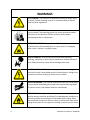
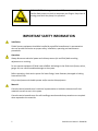
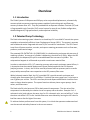
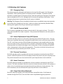
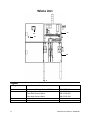
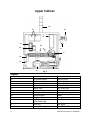
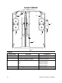
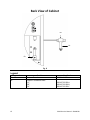
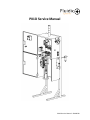
PK1D Service Manual
PK1D Service Manual - 20140618
This manual should be read and understood prior to installing,
operating or servicing the PK1D Unit.
PK1D Service Manual - 20140618
Table of Contents
WARNINGS .................................................................................................................................................... 4
IMPORTANT SAFETY INFORMATION ............................................................................................................. 5
Overview ....................................................................................................................................................... 6
1.1
Introduction .................................................................................................................................. 6
1.2
Patented Pump Technology .......................................................................................................... 6
1.3
Metering Unit Features ................................................................................................................. 7
1.3.1
Emergency Stop .................................................................................................................... 7
1.3.2
Low Air Pressure Switch ........................................................................................................ 7
1.3.3
Linear Displacement Pump (LDP) System ............................................................................. 7
1.3.4
Pressure Transducers ............................................................................................................ 7
1.3.5
Linear Transducer.................................................................................................................. 7
1.3.6
Pump Flush Valves (Optional) ............................................................................................... 7
Whole Unit .................................................................................................................................................... 8
Upper Cabinet ............................................................................................................................................... 9
Regulator Tee Assembly.............................................................................................................................. 10
Upper Cabinet-Side View ............................................................................................................................ 11
Air Solenoid Assembly................................................................................................................................. 12
Gear Box and Servo Motor ......................................................................................................................... 13
Lower Cabinet ............................................................................................................................................. 14
Back View of Cabinet .................................................................................................................................. 15
Unit Installation........................................................................................................................................... 16
Setup ........................................................................................................................................................... 17
Maintenance ............................................................................................................................................... 18
Accessories and Options ............................................................................................................................. 18
PK1D Service Manual - 20140618
WARNINGS
STATIC SHOCK: Can cause fire or explosion resulting in severe injury
or death. Ground metering systems in accordance with all federal,
state and local regulations.
HAZARDOUS PRESSURE: Sudden pressure release can cause severe
injury or death. The metering system can remain pressurized when
the system is not operation. Relieve system pressure before
attempting service or adjustments.
EXPLOSION HAZARD: Do not operate a PK electronic control unit in
an environment of flammable gases or vapor unless it is equipped
with a class I, division 1 air purge system
SAFETY GOGGLES: Must be worn at all times while installing,
servicing, operating, or observing this equipment. Sudden release of
air or fluid pressure can cause serious damage to the eyes.
ELECTROCUTION HAZARD: Disconnect power before servicing
electrical controls. Never defeat electrical safety devices. Doing so can
cause electrocution resulting in severe injury or death.
INJECTION HAZARD: Any material injected into flesh can cause severe
injury or death. Keep body parts away from material discharge ports.
If injection occurs, seek medical attention immediately.
FIRE HAZARD: When flammable solvents are used, smoking or other
ignition sources should be prohibited. Provide adequate ventilation to
prevent ignitable concentrations of flammable vapors. Never allow
the temperature of process fluids to reach or exceed their flash points.
Doing so can cause fire or explosion resulting in severe injury or death.
4
PK1D Service Manual - 20140618
PINCH HAZARD: Moving parts such as LDP’s, servo motor drives and
transfer feed pumps can pinch or amputate your fingers. Keep clear of
moving parts when the pump is in operation.
IMPORTANT SAFETY INFORMATION
Installation
Fluidic Systems equipment should be installed by a qualified manufacturer’s representative
who can provide instruction on proper safety, installation, operating and maintenance
procedures.
Operation
Always disconnect electrical power and relieve pressure (air and fluid) before making
adjustments or servicing.
Do not operate equipment if fluids have solidified. A blockage in the fluid circuit (hoses, valves,
gauge, etc) can cause immediate damage to the system.
Before operating, check entire system for loose fittings, loose fasteners, damaged or leaking
hoses and air lines.
Only trained personnel should operate and/or service this equipment.
Material
Consult material manufacturer’s technical representative or bulletins to determine if their
materials are safe to use in this system.
Consult material manufacturer for safe handling procedure and what precautions are required
when exposed to the materials.
5
PK1D Service Manual - 20140618
Overview
1.1 Introduction
The Fluidic Systems PK Dispense and PK Spray units are positive displacement, volumetrically
accurate plural component metering systems capable of maintaining ratio and flow rate
accuracy to better than ±1%. They are provided with an Operator Interface Terminal (OIT) and
a Programmable Logic Controller (PLC) control system for ease of use, flexible configuration,
detailed diagnostics, high performance, and exceptional reliability.
1.2 Patented Pump Technology
The fixed ratio metering system is based on a closed loop PLC controlled DC servo drive system
coupled to volumetrically efficient Linear Displacement Pumps (LDP’s). The system is accurate
and reliable and can be integrated with user PC/PLC controls for automation. The SPC Closed
Loop Control System monitors, controls, and reports metering parameters such as flow rates,
pressures, and material usage.
The patented LDP (PATENT NO. US 6,398,514 B1) is a double acting rod pump with two sets of
metering cylinders. As one set of cylinders is dispensing, the other set is filling. When the LDP
reciprocates, the dispense/fill cycle is reversed between the two sets of cylinders. The
reciprocation happens in milliseconds to provide a continuous material flow.
In order to maintain the LDP +/-1% metering accuracy and smooth continuous material flow, it
is imperative that the material feed pressure (input) be balanced with the LDP dispense
(output) pressure. In short, the PK units must be pressure fed from pressure pots or transfer
pumps with pressure/flow rates respective to the LDP pressure/flow rates.
With a balanced material feed, the PLC controlled LDP’s provide smooth continuous and
virtually pulse free outputs from 5 to 3500 psi. Precision flow rates range from 5 cc/minute to
over 2 gallons per minute. The LDP’s can meter/mix and dispense differential viscosities from
water to heavy abrasive pastes. The system functions without piston or gear pumps, check
valves, and flow meters.
The fixed ratio PK units have one LDP for both material components. The mix ratio of the
components is achieved by the relative size of one pump rod to the other. Example: for 1:1
volumetric ratio, both rods are the same size; for 2:1 volumetric ratio, one rod will be 1” in dia.
the other rod will be 0.707 in dia. Variable flow rates are achieved by running the LDP slow for
low flow rates or fast for higher flow rates.
To achieve the best performance from this system, it is critical that operators understand and
use the controls and safety features in the correct manner.
6
PK1D Service Manual - 20140618
1.3 Metering Unit Features
1.3.1 Emergency Stop
The yellow mushroom-head push-pull button on the top of the PK system is the Emergency
Stop button. When pressed, power to the pump motors is disabled. The button must be
twisted to re-enable power to the pump motors. Note that pushing the Emergency Stop button
does not disable the OIT or PLC, although the PLC monitors the position of the button. If the
Emergency Stop button is pushed then the PK system is disabled.
Warning: The Emergency Stop is intended as a quick way to immediately stop pump operation
in the event of an emergency of any kind. It does not replace the previously detailed Safety
Warning with regards to servicing or maintaining the equipment.
1.3.2 Low Air Pressure Switch
The PK system is provided with a low air pressure switch in the upper enclosure. The switch
must see at least 80 PSI in order to operate. If the pressure falls below this, then the system is
disabled.
1.3.3 Linear Displacement Pump (LDP) System
Each LDP assembly consists of a Servo drive operating two brushless DC gear motor. The gear
motor turns a gearbox input shaft, and gearbox output shafts turn a screw that moves the LDP.
The LDP ’s each have two sets of fluid cylinders that operate in pairs coupled with a four-way
cross-over valve (x-over), such that one set of cylinders is filling while the other is discharging.
All pump outlets are combined through a static mixing tube or other mixing devices (dynamic
mixer- impingement), which mixes the components. The action of the Servo drives and crossover valves are fully controlled by the OIT/PLC controls.
1.3.4 Pressure Transducers
Each LDP assembly outlet is provided with a pressure transducers monitored by the OIT/PLC
controls. When the pressure for an active pump reaches the pressure set point, all pumps stop.
The pressure transducers are also monitored for open-loop and short-circuit conditions.
1.3.5 Linear Transducer
Each LDP rod pump assembly is provided with a linear transducer monitored by the OIT/PLC
controls. The linear transducers allow the controls to know the exact positions of the pumps, in
order to turn it around during normal operation and to provide over-travel protection. The
linear transducers are also monitored for open-loop and short-circuit conditions.
1.3.6 Pump Flush Valves (Optional)
Each LDP rod pump assembly can be provided with a pump flush valve. If this feature is
enabled through the OIT/PLC, then the flush valves are pulsed during pump operation.
7
PK1D Service Manual - 20140618
Whole Unit
AC
AA
AB
AD
Fig. 1
Legend:
Diagram Name
AA
AB
AC
AD
8
Part Name
Programmable Logic Control (PLC)
Emergency Stop Button
Two-Node Contact Block
One-Node Contact Block
Upper Cabinet
Lower Cabinet
Part Number
009-PR-TS-212
009-PR-ES-004
009-PR-CB-005
009-PR-CB-138
None
None
PK1D Service Manual - 20140618
Upper Cabinet
BN
BC
BF
BD
BA
BH
BB
BE
BJ
BG
BK
BL
Legend:
BA
BB
BC
BD
BE
BF
BG
BH
BJ
BK
BL
BM
9
Diagram Name
Fig. 2
Part Name
24V Power Supply
5V Power Supply
Expansion Module
Amplifier
Water Trap
Pressure Gauge
Air Solenoid Assembly
Terminal Block
Regulator Tee Assembly
110V Power Plug
220V Power Plug
Gear Box
Motor Assembly
Part Number
009-PR-PS-114
009-PR-PS-113
009-RP-EM-214
009-PR-SA-180
007-PR-WT-001
007-PR-PG-017
None (shown on page #)
MANY
None (shown on page #)
009-PR-FI-168
See Page #
009-PR-SM-125
PK1D Service Manual - 20140618
BN
4 Unit Light Stack
3 Unit Light Stack
2 Unit Light Stack
009-PR-SL-208
009-PR-SL-207
009-PR-SL-199
Regulator Tee Assembly
CG
CF
CD
CD
CB
CA
CE
CC
Fig. 3
Legend:
CA
CB
CC
CD
CE
CF
CG
10
Diagram Name
Part Name
Air Regulator
Pipe Cross
Air Vent
Hex Nipple
Brass Bulkhead
Reduced Bushing
Pressure Switch
Part Number
007-PR-AR-018
006-PR-PC-033
007-PR-AM-025
006-PR-HN-018
005-PR-FB-222
005-PR-RB-113
009-PR-PS-077
PK1D Service Manual - 20140618
Upper Cabinet-Side View
DH
DA
DD
DE
DC
DB
DF
DG
Fig. 4
Legend:
DA
DB
DC
DD
DE
11
Diagram Name
Part Name
Air Solenoid Assembly
110V Power Plug
220V Power Plug
Air Regulator
Brass Bulkhead ¼”
Strain Relief
Part Number
Shown On Next Page
009-PR-FI-168
007-PR-AR-018
005-PR-FB-222
009-PR-SR-058
PK1D Service Manual - 20140618
DF
DG
DH
Trigger Connector
Air Dispense Valve On/Off
Tube Fitting
009-PR-CP-095
009-PR-BF-012
006-PR-ME-017
Air Solenoid Assembly
EA
ED
EB
EC
ED
EE
EF
Fig. 5
Legend:
EA
EB
EC
ED
EE
EF
12
Diagram Name
Part Name
Solenoid Right End Cap
Control Block 1/4"
Control Block 5/16”
24V Solenoid
Air Exchange Block
Solenoid Left End Cap
Part Number
007-PR-EC-008
007-PR-CB-006
007-PR-CB-009
007-PR-SB-010
007-PR-AB-007
007-PR-EC-004
PK1D Service Manual - 20140618
Gear Box and Servo Motor
FA
FC
FB
FD
FE
Fig. 6
Legend:
FA
FB
FC
FD
FE
13
Diagram Name
Part Name
Mount Spacer
Servo Motor Mount
Mount Coupler
Servo Motor
Gear Box
10:1
20:1
25:1
60:1
Part Number
015-SP-PH-020
015-MT-AL-005-FP
015-PR-JC-021
009-PR-SM-125
016-MC-GB-035 (A or B/C)
016-MC-GB-027 (A or B/C)
016-MC-GB-001 (A or B/C)
016-MC-GB-002 (A or B/C)
PK1D Service Manual - 20140618
Lower Cabinet
EA
EA
EF
EB
EC
ED
EE
Fig. 7
Legend:
Diagram Name
EA
EB
EC
ED
EE
EF
14
Part Name
Outlet Pressure Transducer
Cross-Over A-Mount Assembly
Cross-Over B-Mount Assembly
Inlet Pressure Transducer Block
1/2"
3/8”
1/4"
Linear Displacement Pump Assembly
Pressure Transducer
Part Number
003-MT-SS-026-A
100-SA-XV-051 (A)
100-SA-XV-051 (BC)
003-MT-SS-026-A
003-MT-SS-026-B
003-MT-SS-026-C
100-SA-LP-017
009-PR-PT-162
PK1D Service Manual - 20140618
Back View of Cabinet
FB
FA
FB
Fig. 8
Legend:
Diagram Name
FA
FB
15
Part Name
Pressure Transducer
Pressure Transducer Block
1/2"
3/8”
1/4"
Part Number
100-SA-LS-090
003-MT-SS-026-A
003-MT-SS-026-B
003-MT-SS-026-C
PK1D Service Manual - 20140618
Unit Installation
2.1
Grounding
2.2
Power
The cabinet must be grounded to prevent static and electric shock. This is done by an escape
wire that electrical current, due to static build, can travel through. To ground the cabinet, take
the grounding-clamp at the end of the ground wire and connect it to a true earth ground. The
other end of the grounding wire is already connected to the cabinet. Grounding bands should
be worn at all time by anyone who is operating the unit.
To give unit power, connect chord to 110 or 220 Volt power supply.
16
PK1D Service Manual - 20140618
Setup
Priming the Pump
1.
2.
3.
4.
5.
Load material/fluid into the transfer pumps or pressure pots
Using the touch screen, set the flow rate to 30%
Open the air valve
Set pressure to set point (inlet pressure should be about within 10% of outlet pressure)
Pump will begin to move. Open the bleeder valve on transfer pump with a waste-cup
until air is completely out of material
6. On the LDP upstroke, crack the upper hose nut at the cylinder manifold. Then close the
nut before the down stroke. This removes the air from the rest of the system
Flushing the Pump
1.
2.
3.
4.
5.
Load the transfer pumps or the pressure pots with flushing material
Set the air pressure to the pressure set point
Connect the outbound hose to the flush inlet fitting
Using the touch screen, locate the flush page. Set the appropriate pump(s) to be flushed
Stop the flushing process when the material is completely out of the system
Pressure Relief Procedure
1. Disable the PK unit
2. Check the touch screen to find the pressure readings
3. Based on the pressure reading, located the proper nut and loosen it to relieve the
pressure
17
PK1D Service Manual - 20140618
Maintenance
The XV2 Cross-Over valves must be greased as well as the cylinder nut reservoirs on the LDP.
Refer to the Linear Displacement Pump manual 100-SA-LP-017 and to the Cross-Over manual
100-SA-RK-053 (065) for maintenance procedures.
Accessories and Options
Foot Switch
The Foot Switch hooks up to the trigger connector located on the side of the PK1D unit. In shot
mode, the foot-switch needs to be switch on and the system will dispense fluid for the time the
operator has set.
Dispense Valve Hand Gun
The Hand Gun hooks to the trigger connector located on the side of the PK1D unit and
dispenses the fluid. The Gun must be occasionally greased.
Robotic Interface
The Robotic Interface enables the digital robotic input to start/stop the pump.
Light Stack
The Light Stack indicates the state of the machine. The green light indicates the machine is
operational. The amber light indicates the machine is in stand-by mode. The red light indicates
there is a fault.
18
PK1D Service Manual - 20140618