1
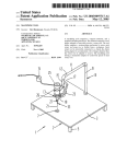
MODELS
ZAP-40 & ZAP-62
Air Hydraulic Foot/Hand Pump
Toll Free: 1-800-579-8088 Web: www.zinko.com
Operating Instructions & Repair Parts List
Operator Responsibilities
It is the operator's responsibility to read and understand the following safety statements. Only qualified operators should
install, operate, adjust, maintain, clean, repair, or transport this machinery. These components are designed for general
use in normal environments. These components are not specifically designed for lifting and moving people, agri-food
machinery, certain types of mobile machinery, or special work environments such as: explosive, flammable, or corrosive.
Only the user can decide the suitability of this machinery in these conditions or extreme environments. ZINKO will supply
information necessary to help make the decision. These instructions are intended for end-user application needs. Most
problems with new equipment are caused by improper operation or installation. A detailed parts list can be obtained from
ZINKO upon request.
All Warning Statements must be carefully observed to help prevent personal injury.
1. Before operating the pump, all hose connections must be tightened with proper tools. DO NOT OVER TIGHTEN.
Connections should only be tightened securely and leak-free. Over tightening can cause premature thread failure
or high pressure fittings to split at pressures lower than their rated capacities. Should a hydraulic hose ever
rupture, burst, or need to be disconnected, immediately shut off the pump and release all pressure. Never
attempt to grasp a leaking pressurized hose with your hands. The force of escaping hydraulic fluid could cause
serious injury.
2. DO NOT subject the hose to potential hazards such as fire, sharp surfaces, extreme heat or cold, or heavy
impact. Do not allow the hose to be altered or kink, twist, curl, crush, cut, or bend so tightly that the fluid
flow within the hose is blocked or reduced. Periodically inspect the hose for wear, because any of these
conditions can damage the hose and possibly result in personal injury.
3. DO NOT USE THE HOSE TO MOVE ATTACHED EQUIPMENT. Stress can damage hose and possibly cause
personal injury.
4. Hose material and coupler seals must be compatible with the hydraulic fluid used. Hoses also must not come
in contact with corrosive materials such as creosote-impregnated objects and some paints. Consult the
manufacturer before painting a hose. Hose deterioration due to corrosive materials can result in personal
injury. NEVER PAINT COUPLERS.
5. Inspect machine for wear, damage, and correct function before each use. Do not use machinery that is not in
proper working order, but repair or replace it as necessary.
6. REPLACE WORN OR DAMAGED SAFETY DECALS.
7. MODIFICATION OF A PRODUCT REQUIRES WRITTEN ZINKO AUTHORIZATION.
8. Use only components with the same pressure rating when assembling a system or machine.
PUMP
1. DO NOT EXCEED THE HYDRAULIC PRESSURE RATING NOTED ON THE PUMP DATA PLATE OR TAMPER
WITH THE INTERNAL HIGH PRESSURE RELIEF VALVE. Creating pressure beyond the rated pressure can result
in personal injury.
2. Before replenishing the fluid level, retract the system to prevent overfilling the pump reservoir. An overfill can
cause personal injury due to excess reservoir pressure created when cylinders are retracted.
AIR SUPPLY
1. SHUT OFF AND DISCONNECT THE AIR SUPPLY WHEN THE PUMP IS NOT IN USE OR BEFORE BREAKING
ANY CONNECTIONS IN THE SYSTEM.
Preparations & Setup
Air Supply Hook-up
Remove the thread protector from the air inlet of the pump. Select and install the threaded fittings which are compatible
with your air supply fittings. The air supply should be 20 CFM (.57 M3/mm.) and 100 psi (7 bar) at the pump to obtain
the rated hydraulic pressure. Air pressure should be regulated to a maximum of 140 psi (9 bar). Secure your pump fitting
to the air supply.
If improperly used, pressurized equipment can be potentially hazardous. Therefore:
1. Hydraulic connections must be securely fastened before building pressure in the system.
2. Release all system pressure before loosening any hydraulic connection in the system.
Operating Instructions
Hydraulic Connections
Clean all the areas around the fluid ports of the pump and cylinder. Inspect all threads and fittings for signs of damage
and replace as needed. Clean all hose ends, couplers, and union ends. Remove the thread protectors from the hydraulic
fluid outlets. Connect the hose assembly to the hydraulic fluid outlet and couple the hose to the cylinder.
Zinko Hydraulic Jack
Models: ZAP-40 & ZAP-62 Operating Instructions (continued)
IMPORTANT: Seal all external pipe connections with high grade thread sealant. Teflon tape may also be used to seal
hydraulic connections, provided only one layer of tape is used. Apply the tape carefully, two threads back, to prevent it
from being pinched by the coupler and broken off inside the system. Any loose pieces of tape could travel through the
system and obstruct the flow of fluid or cause jamming of precision-fit parts.
Priming the Pump Unit
Under certain circumstances it may be necessary to prime the pump unit. To do so, follow these instructions:
For Hand/Foot Pumps:
1. Press the release end of the pedal while holding down the air intake valve with a flattened screwdriver. The air intake
valve is located directly under the pedal in the area marked "PUMP". The air intake valve is depressed simultaneously
with the "RELEASE" area of the pedal during priming.
2. Allow the pump to cycle for approximately 15 seconds.
3. Remove the screwdriver, and press the "PUMP" end of the pedal once more.
4. If the cylinder extends or pressure builds, the pump has been successfully primed. If the pump does not respond,
repeat the procedure, jogging the air intake valve while holding the pedal in the "RELEASE" position.
Pump Operation
Activating the pump with the pedal end marked with
this picogram, the fluid is directed out of the reservoir.
Activating the pump with the pedal end marked with
this picogram, the fluid is directed back to the reservoir.
For Hand/Foot Operated Pumps:
1. To extend the cylinder, depress the pedal on the end marked "PUMP".
2. To hold the cylinder in position, release the end of the foot pedal marked with "PUMP" to deactivate the pump.
3. To retract the cylinder, depress the pedal on the end marked "RELEASE".
For Pumps With Air Regulators:
1. Open the air shut-off valve (if so equipped) or connect the air quick coupler (if so equipped). NOTE: Under certain
circumstances the pump may need to be primed before operation.
2. Slowly turn the air regulator control on unit clockwise to increase pressure, counterclockwise to decrease pressure.
As air is admitted to the pump unit, it will begin to deliver fluid to the system. Continue to slowly turn the air
regulator control clockwise until the gauge reads the maximum hydraulic pressure rating as stated on the pump's
data plate. A maximum hydraulic pressure reading should be obtained is air pressure is approximately 100 psi (7 bar).
3. Cycle the system several times by manually shifting the 3-way/4-way valve (if so equipped) or the remote valve (if
so equipped). Set the air regulator to obtain the desired hydraulic pressure. When decreasing air pressure, shift the
valve after each adjustment before measuring actual hydraulic pressure.
4. Shut off and disconnect air supply to the pump and shift pump valve (if so equipped) or remote valve (if so equipped)
two times to release all system pressure. Check fluid level with the hydraulic system retracted. THE PUMP IS NOW
READY FOR OPERATION. Note: The Hydraulic pressure is increased or decreased by adjusting the air inlet pressure
at the regulator.
2-Stage Pumps
On two-stage pumps, the air pressure regulator that is mounted on the pump controls only the output from the high
pressure stage. The output of the low pressure stage of the pump is determined by the air line pressure coming from the
remote regulator. A remote regulator is required to control the air pressure from the line. The independent functioning of
the low and high pressure stages of this pump can be best described as follows: At the minimum air line pressure of 40
psi (3 bar), the low pressure stage of the pump will deliver 480 psi (33 bar) hydraulic pressure (with the pump regulator
turned counterclockwise to prevent air pressure from activating the high stage of the pump). At the minimum air line
pressure of 40 psi (3 bar) the high pressure stage of the pump will deliver 4,000 psi (275 bar) hydraulic pressure (with
the pump regulator turned clockwise to allow air pressure to reach the high pressure stage). Always remember that the
pump regulator must be turned fully counterclockwise when the pump is used to produce 1,200 psi (83 bar) or less.
Preventive Maintenance
IMPORTANT: Any repair or servicing that requires dismantling that pump must be performed in a dirt-free environment
by a qualified technician. Dispose of machine fluids properly.
Draining and Flushing the Reservoir
IMPORTANT: Wipe the pump exterior completely clean before attempting this procedure.
1. Drain the bladder of all oil and refill half full with clean hydraulic oil. Rinse the filter clean.
2. Run the unit for several minutes.
3. Drain and clean the bladder once more.
4. Refill the bladder with hydraulic oil.
IMPORTANT: Drain and clean the other hydraulic system components (hoses, cylinders, etc.) before reconnecting them
to the pump. This will prevent contaminated fluid from entering the pump again.
Zinko Hydraulic Jack
Models: ZAP-40 & ZAP-62 Preventive Maintenance (continued)
Lubrication
For Hand/Foot Pumps: If the pump is operated on a continuous duty cycle for extended periods, the manufacturer
recommends installing an automatic air line oiler in the air inlet as close to the pumping unit as possible. Set the unit to
feed approximately one drop of oil per minute into the system. Use SAE No.10 Oil.
Bleeding Air From the System: During the first moments of operation after prolonged use, a significant amount of air
may accumulate within the hydraulic system. This entrapped air may cause the cylinder to respond slowly or behave in
an unstable manner. To remove the air, run the system through several cycles (extending and retracting the cylinder) free
of any load. The cylinder must be at a lower level than the pump to allow air to be released through the pump reservoir.
Inspecting the Hydraulic Fluid Level: Check the fluid level in the bladder after every 10 hours of use. Drain and replenish
the bladder with approved hydraulic fluid after approximately 300 hours of use. For pumps with a 67 cubic inch (1.0 L)
bladder capacity: Follow the same inspection procedures as mentioned above.
Refilling the Bladder: If additional fluid must be added to the bladder, use only approved hydraulic fluid (215 SSU @
100o F (38o C)). Clean the entire area around the filler plug before adding fluid to the bladder. Remove the filler plug,
and insert a clean funnel with filter. The cylinder must be fully retracted and the air supply disconnected when adding
the fluid to the bladder.
Periodic Cleaning
IMPORTANT: The greatest single cause of failure in hydraulic pumps is dirt. Keep the pump and attached equipment
clean to prevent foreign matter from entering system.
A routine should be established to keep the pump as free from dirt as possible. All unused couplers must be sealed with
thread protectors. All hose connections must be free of grit and grime. Any equipment hooked up to the pump should
also be kept clean. Use only approved hydraulic fluid in this unit and change as recommended (every 300 hours).
Accessories
Gauges and accessories may not be included with the pump. However, a hydraulic gauge is strongly recommended
whenever the pump is used.
1. The gauge MUST BE of the proper rating for the pressure used.
2. Use only ZINKO approved accessories, hydraulic fluid, and repair parts.
Installing An In-line Air Pressure Gauge
1. Remove the male fitting from the air filter and install a tee adapter with gauge between the hose and air filter.
2. Install male fitting into the tee adapter and securely clamp the hose to the male fitting.
Installing An In-line Hydraulic Pressure Gauge
1. Remove the thread protector from the hydraulic outlet port and inspect the threads and fittings for signs of wear.
2. Install a tee adapter, with gauge, between the hose coupling and the pump hydraulic outlet port.
3. Tighten all connections securely. DO NOT OVER TIGHTEN HOSE CONNECTIONS.
Troubleshooting
PROBLEM
CAUSE
1. Low fluid level.
Pump Reciprocates
But No Fluid Delivery
(cylinder will not extend).
2. Pump not primed.
3. Fluid intake filter contaminated.
Low Fluid Delivery
(cylinder extends slowly).
Pump Will Not Build To
Maximum Pressure
(no visible leakage).
Pump Builds Pressure
But Will Not Hold
System Pressure.
SOLUTION
1. Add fluid as instructed in Preventive
Maintenance section.
2. Prime pump as instructed in Operation
section.
3. Remove reservoir and clean intake filter
and reinstall.
1. Inadequate air supply.
a) Check air input supply.
b) Contamination, check air side
of pump (plugged air inlet screen)
2. Hydraulic failure.
a) Check the fluid inlet filter for
contamination.
b) Air in hydraulic system.
1.a) Should be 20 CFM (.57 M3/min.)
minimum.
b) Clean and reassemble.
1. Check the air supply.
1. 100 psi (7 bar) is required to obtain
maximum pressure.
2. Adjust according to instructions in
Operation section.
2. Pressure regulator improperly
adjusted (if so equipped).
1. Check hydraulic connections and
other system components for leakage,
including 3-way/4-way valve.
2.a) Remove reservoir and clean intake
filter and reinstall.
b) Bleed the system as described in the
Preventive Maintenance section.
1. Refit or repair as needed.
Zinko Hydraulic Jack
Model: ZAP-40 & ZAP-62
REV 071107
Troubleshooting (continued)
PROBLEM
CAUSE
SOLUTION
Pump Will Continue To Run
Slowly Even After Desired
Pressure Is Reached.
1. Output pressure equal or higher
than relief valve setting.
2. Defective 3-way/4-way valve or
other components leaking.
1. Normal operation.
Excess Oil Spray From Muffler.
1. Air lubricator is set too rich (if so
equipped).
1. Set at one drop per minute.
2. Repair or replace.
If the above procedures do not correct the problem, contact your nearest ZINKO service facility. When submitting any jack or
equipment to be repaired, be sure to state the nature of the problem and indicate whether an estimate of the repair cost is needed.
Parts Breakdown
Part #
920040-01
920040-02
920040-03
920040-04
920040-05
920040-06
920040-07
920040-08
920040-09
920040-10
920040-11
920040-12
920040-13
920040-14
920040-15
920040-16
920040-17
920040-18
920040-19
920040-20
920040-21
920040-22
920040-23
920040-24
Description
NUT
CAP
COUPLER
SCREW M6*16L
CYLINDER TOP CAP
AIR BAG
ALUMINUM CYL. TUBE
E-RING E-15
CONNECTOR PLATE
BUSHING
SCREW
O-RING P12
BACKUP RING P14
O-RING P14
SCREW
STEEL BALL 3/16"
OVRLD. SPRING END CAP
OVRLD. SPRING
ADJ. VALVE BOLT
O-RING P5
ADJ. VALVE BASE
SCREW
BUSHING
PLUG
Part #
920040-25
920040-26
920040-27
920040-28
920040-29
920040-30
920040-31
920040-32
920040-33
920040-34
920040-35
920040-36
920040-37
920040-38
920040-39
920040-40
920040-41
920040-42
920040-43
920040-44
920040-45
920040-46
920040-47
920040-48
Description
SPRING
STEEL BALL 7/32"
BACKUP RING P12
VALVE BASE
O-RING P16
RELEASE VALVE BASE
RELEASE SPRING
O-RING P6
PIN
RELEASE VALVE BOLT
PEDAL
SCREW M5*8L
O-RING G65
FILTER
ALUMINUM PUMP BASE
SILENCER
SPRING
LOW SPRING
STEEL BALL 8MM
HIGH SPRING
COPPER WASHER
HIGH SCREW
PUMP CYLINDER
U-RING
Part #
920040-49
920040-50
920040-51
920040-52
920040-53
920040-54
920040-55
920040-56
920040-57
920040-58
920040-59
920040-60
920040-61
920040-62
920040-63
920040-64
920040-65
920040-66
920040-67
920040-68
920040-69
920040-70
920040-71
920040-72
Description
BACKUP RING
BUSHING
PUMP CYLINDER UNIT
SILENCER
U-WASHER
PUMP SPRING
PISTON WASHER
PISTON BOLT WASHER
PISTON
AIR STEEL TUBE
O-RING
PISTON B
O-RING P21
CHANGE PISTON
PISTON A
CAP
SCREW M5*18L
O-RING S70
TOP CAP
AIR INLET VALVE
SPRING
SCREW
FILTER
AIR COUPLER
(909)989-9526
(909)989-1724