1
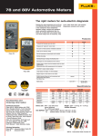
® 78 Automotive Meter Users Manual For IEC 61010 CAT II Meters Only PN 666625 November 1998 Rev.1, 9/00 © 1998, 2000 Fluke Corporation. All rights reserved. Printed in U.S.A. All product names are trademarks of their respective companies. Table of Contents Title What is in the Manual.................................................................................................... Using the Meter Safely .................................................................................................. Getting Acquainted with the Meter ................................................................................ Rotary Switch ........................................................................................................... Input Jacks ............................................................................................................... Thermocouple Adapter ............................................................................................. Display...................................................................................................................... RPushbutton....................................................................................................... Standby (Sleep) Mode.............................................................................................. Bar Graph ................................................................................................................. Autorange with "Floor".............................................................................................. Typical Testing Applications.......................................................................................... G,F How to Measure Voltage ................................................................................... L How to Test Diodes .......................................................................................... N, AdHow to Measure Current .............................................................................. w How to Test Continuity........................................................................................ J How to Measure Resistance ................................................................................. RPM ut How to Measure RPM with the RPM80 Inductive Pickup (Optional) ........ i Page 1 1 4 4 6 6 8 10 10 12 12 14 14 16 18 20 22 24 78 Users Manual Hz s How to Use DC-Coupled HZ to Check BP/MAP Sensors ............................. Hz d How to Use AC-Coupled Hz on a Crankshaft Position Sensor .................... m How to Measure Dwell on Conventional Ignitions ........................................... % How to Measure Duty Cycle on a Feedback Carburetor...................................... °C °F How to Measure Temperature on a Coolant Temperature Sensor.................. How to Store Minimum and Maximum Measurements................................................... How to Use the Bar Graph to Test a Throttle Position Sensor....................................... How to Lock the Meter in a Measurement Range.......................................................... Using the Holster and Flex-Stand .................................................................................. Maintenance .................................................................................................................. Cleaning.................................................................................................................... Calibration................................................................................................................. How to Test the Fuse ................................................................................................ How to Replace the Battery or Fuse ......................................................................... Accessories and Parts ................................................................................................... Specifications................................................................................................................. ii 26 28 30 32 34 36 38 40 40 42 42 42 42 42 42 46 List of Tables Table 1. 2. 3. 4. Title Page Symbols ............................................................................................................................. Measurement Unit Symbols ............................................................................................... Pushbutton Operations ...................................................................................................... Replacement Parts and Accessories ................................................................................. 1 8 11 45 iii 78 Users Manual iv List of Figures Figure 1. 2. 3. 4. 5. 6. 7. 8. 9. 10. 11. 12. 13. 14. 15. 16. 17. Title Page Rotary Switch ..................................................................................................................... Input Jacks ......................................................................................................................... Display ............................................................................................................................... Interpreting the Bar Graph ................................................................................................. Measuring No-Load Voltage of Battery .............................................................................. Testing Diodes in Alternator Rectifier Bridge ..................................................................... Isolating Circuit Causing Current Drain.............................................................................. Testing Continuity in a Switch ............................................................................................ Measuring Resistance to Check Coolant Temperature Sensor ......................................... Measuring RPM with the (Optional) Inductive Pickup ........................................................ Checking Barometric Pressure/Manifold Absolute Pressure Sensor ................................. Using AC Coupled-Frequency on a Crankshaft Position Sensor ....................................... Measuring Dwell on a Conventional Ignitions .................................................................... Measuring Duty Cycle on a Feedback Carburetor ............................................................. Measuring the Temperature of Coolant Temperature Sensor............................................ Using MIN MAX to Check an Oxygen Sensor .................................................................... Using Bar Graph to Observe Sweep of Throttle Position Sensor (TPS) ............................ 5 7 9 13 15 17 19 21 23 25 27 29 31 33 35 37 39 v 78 Users Manual 18. 19. 20. 21. Holster and Flex-Stand ....................................................................................................... Fuse Test............................................................................................................................ Fuse and Battery Replacement .......................................................................................... Replacement Parts ............................................................................................................. vi 41 43 44 45 IGNITION/ENGINE Coils Computer Temp Sensors Condensers (Capacitors) Connectors Contacts Set Distributor Cap Engine Speed Feedback Carburetors Fuel Injectors (Electronic) Hall-Type Sensors Idle Air Motors Ignition Modules MAF Sensor Magnetic Pickups MAP & BP Sensors 02 Sensors Throttle Position Sensors STARTING SYSTEM Battery Connectors Interlocks (neutral safety switch) Solenoids Starters * Used with Fluke 80i-410 or 80i-1010 current clamp. ** With optional RPM 80 Inductive Pickup accessory. M ill iv M olt IN s M O hm AX R s PM Te ** m Vo per lts atu Vo AC re lts D C ps ar DC G * C ra on ph tin ui ty % D ut D y w el Cy cl H l e z B A m APPLICATIONS GUIDE A m p B sD ar G C* C ra on p tin h ui ty % D D uty w el Cy cl H l e z M ill iv M olt IN s O MA hm X s R PM Te ** m p Vo er lts atu Vo A re lts C D C APPLICATIONS GUIDE (cont) COOLING SYSTEM Connectors Fan Motor Radiator Relays Temperature Sensors Temperature Switches CHARGING SYSTEM Alternators Computerized Regulators Connectors Diodes, (AC Ripple) Diode Rectifier Regulators BODY ELECTRIC Compressor Clutch Lighting Circuits Relay and Motor Diodes Transmissions * Used with Fluke 80i-410 or 80i-1010 current clamp. ** With optional RPM 80 Inductive Pickup accessory. DISPLAY 78 AUTOMOTIVE METER AC DC mV Mk Hz RPM 1 2 BAR GRAPH 0 MAX OFF 1 MIN 2 3 AUTO 4000 V SKID RESISTANT PADS V Hz V Hz PHILLIPS-HEAD SCREWS PUSHBUTTON RPM ROTARY SWITCH 2 1 °C°F A PRESS MIN / MAX Hz 1 RPM 1 SEC 2 SEC V + INPUT JACKS 10A 300V 30V °C°F CAT 30V WARNING TO AVOID DAMAGE OR INJURY, USE ONLY IN PROTECTED CIRCUITS WHICH CAN NOT EXCEED 4800 VOLT-AMPS. TO PREVENT FIRE, INSTALL FUSE WITH AMP/VOLT RATINGS SHOWN. TO AVOID ELECTRICAL SHOCK, REMOVE TEST LEADS BEFORE OPENING CASE. F 15A 600V MIN INTERRUPT RATING 10 000A 9V NEDA 1604 6F22 006P COM FLUKE CORPORATION MADE IN USA U.S. PATENTS: 4,556,867 4,532,470 FUSED FRONT BACK SAFETY INFORMATION FUSE RATING BATTERY TYPE What is in the Manual Warning Read "Using the Meter Safely" before using the meter. Note The automotive tests included in this manual are intended to help you learn how to use the meter. Consult your car’s service manual for specific procedures that apply to your car. What is in the Manual This manual provides safety information, operating instructions, basic maintenance procedures, and specifications for the Fluke 78 Automotive Meter (referred to as "the meter"). To contact Fluke, call one of the following telephone numbers: USA: 1-888-99-FLUKE (1-888-993-5853) Canada: 1-800-36-FLUKE (1-800-363-5853) Europe: +31 402-678-200 Japan: +81-3-3434-0181 Singapore: +65-738-5655 Anywhere in the world: +1-425-446-5500 Or, visit Fluke’s Web site at www.fluke.com Refer to the 78 Service Manual (P/N 666617) for complete servicing information. If the meter is damaged or something is missing, contact the place of purchase immediately. Fluke Corporation P.O. Box 9090 Everett WA 98206-9090 Fluke Europe B.V. P.O. Box 1186 5602 B.D. Eindhoven, The Netherlands Using the Meter Safely Use the meter as described in this manual. Otherwise the safety features provided by the meter might be impaired. A Warning identifies conditions and actions that pose hazards to the user; a Caution identifies conditions and actions that might damage the meter. International electrical symbols used on the meter are shown in Table 1. Table 1. Symbols Symbol Meaning Important information. See manual. Alternating current (AC) Direct current (DC) Alternating or direct current (AC or DC) Diode Ground Fuse Double insulation (Protection Class II) Conforms to European Union directives 1 78 Users Manual • Do not operate the meter around explosive gas, vapor or dust. • Do not apply more than the rated voltage, as marked on the meter, between terminals or between any terminal and earth ground. • Before each use, verify the meter’s operation by measuring a known voltage. To avoid possible electric shock or personal injury: • When servicing the meter, use only specified replacement parts. • Avoid working alone. • • Do not use the meter if it is damaged. Before use, inspect the case for cracks or missing plastic. Pay particular attention to the insulation surrounding the connectors. Use caution when working above 30 V ac rms, 42 V ac peak, or 60 V dc. Such voltages pose a shock hazard. • Keep your fingers behind the finger guards on the probe when making measurements. Read First: Safety Information This meter complies with EN 61010-1:1993, ANSI/ISA S82.01-1994 and CAN/CSA C22.2 No. 1010.1-92 Overvoltage Category II. Use the meter only as specified in this Users Manual, otherwise the protection provided by the meter may be impaired. Warning 2 • Inspect the test leads for damaged insulation or exposed metal. Check test lead continuity. Replace damaged leads. • Connect the common test lead before connecting the live test lead. Disconnect the live test lead first. • Do not use the meter if it operates abnormally. Protection may be impaired. When in doubt, have the meter serviced. • Remove test leads from the meter before opening the case. Using the Meter Safely • Use only a single 9 V battery, properly installed in the meter case, to power the meter. • Follow all equipment safety procedures. • Before measuring current, check the meter’s fuses (see “How to Test the Fuse”). • Never touch the probe to a voltage source when the test leads are plugged into the 10 A input jack. • Always use clamp-on probes (dc current clamps) when measuring current exceeding 10 A. • DO NOT connect thermocouple to voltages exceeding 30 V. • To avoid false readings, which could lead to possible electric shock or personal injury, replace the meter’s battery as soon as the low battery indicator (N) appears. Caution To avoid possible damage to the meter or to equipment under test: • Disconnect the power to the circuit under test and discharge all high voltage capacitors before testing resistance, continuity or diodes. • Use the proper function and range for your measurement applications. • When measuring current, turn off circuit power before connecting the meter in the circuit. Remember to place the meter in series with the current. 3 78 Users Manual Getting Acquainted with the Meter Rotary Switch Turn the rotary switch (Figure 1) from OFF to another switch setting to turn the meter ON. The display lights for 1 second as part of a selftest routine. The meter is now ready to take measurements. 4 Each switch setting has a primary AND an alternate function. Primary functions are in white; alternate functions are in yellow. To toggle between a primary and alternate function, hold down the push-button for 2 seconds. Getting Acquainted with the Meter VOLTS AC OR AC-COUPLED HZ VOLTS DC OR DC-COUPLED HZ V Hz OFF V Hz DWELL OR DUTY CYCLE PUSHBUTTON (See Table 3) RPM (WITH OPTIONAL RPM 80) RPM 2 1 RESISTANCE OR CONTINUITY TEST A °C°F TEMPERATURE OR DIODE TEST AMPS DC OR AC mt01f.eps Figure 1. Rotary Switch 5 78 Users Manual Input Jacks Warning To avoid personal injury or equipment damage, never attempt a voltage measurement if a test lead is in the 10A jack. The meter has four input jacks (Figure 2) that are protected against overloads to the limits shown on the front and back of the meter. Thermocouple Adapter Warning To avoid possible electric shock or personal injury, do not connect the thermocouple to voltages exceeding 30 V. 6 The 80BK Thermocouple Adapter allows you to use a thermocouple to measure temperature. If the adapter gets lost or damaged, replace the adapter with a Flukespecified part (see Table 4) to ensure optimum performance of the thermocouple. The meter measures temperature using Type-K thermocouple probes. This thermocouple is suitable for making surface temperature measurements from -40°C (or °F) to 260°C (500°F) in teflon-compatible environments. Warning To avoid personal injury or equipment damage, do not use this thermocouple in liquids or at temperatures above 260°C (500°F). At these temperatures the teflon insulation can emit toxic gases. Getting Acquainted with the Meter RPM RPM 10A VOLTS, OHMS, DIODE TEST, DWELL, DUTY CYCLE, TEMPERATURE, CONTINUITY AND HZ V + 300V 30V °C°F CAT 30V COM FUSED AMPS (10 A CONTINUOUS, 20 A FOR <30 SEC) OR COMMON FOR RPM COMMON (RETURN) JACK FOR VOLTS, OHMS, DIODE TEST, TEMPERATURE, DWELL. DUTY CYCLE, CONTINUITY, AND HZ mt02f.eps Figure 2. Input Jacks 7 78 Users Manual Table 2. Measurement Unit Symbols Display Readings are shown on a liquid crystal display (LCD). Symbols on the display indicate what the meter is doing. See Figure 3 and Table 2. If a measurement is too large to be displayed, OL (overload) is shown on the display and the whole bar graph lights. Warning To avoid false readings, which could lead to possible electric shock or personal injury, replace the battery as soon as the battery indicator (N) appears. Symbol AC DC V Hz RPM1 RPM2 q p oL % r Ω k M m 8 Meaning Alternating current or voltage Direct current or voltage Volts Hertz (cycles/second). Frequency Revolutions/minute. 1 RPM count/spark Revolutions/minute. 2 RPM counts/spark Degrees Celsius Degrees Fahrenheit Number of Cylinder Percent (for duty cycle readings) Degrees of rotation (for dwell readings) Ohms. Resistance Kilo. Units x 1,000 Mega. Units x 1,000.000 Milli. Units x 1/1,000 Getting Acquainted with the Meter (CELSIUS) (OVERLOAD) (FAHRENHEIT) REPLACE BATTERY CONTINUITY TEST AND DIODE TEST BAR GRAPH POLARITY OR TRIGGER SLOPE FOR DUTY CYCLE AND DWELL 78 AUTOMOTIVE METER AC DC mV Mk Hz RPM 1 2 0 MAX 1 MIN 2 3 AUTO MEASUREMENT UNITS (See Table 2) 4000 V MEASUREMENT RANGE OR RANGE FLOOR BOTH FLASH FOR PRESENT READING MAXIMUM READING AUTORANGE ENABLED MINIMUM READING BAR GRAPH SCALE (0, 1, 2, 3, 4) BAR GRAPH mt03f.eps Figure 3. Display 9 78 Users Manual R Pushbutton The meter acknowledges a 2 second press by a click, a single beep, and a double beep. The display briefly shows "- - - -". The pushbutton selects different operations, depending on the position of the rotary switch AND how long you hold it down. See Table 3: Pushbutton operations are summarized in Table 3. • Standby (Sleep) Mode Press R for less than 1 second (a "momentary" press) to perform stepping or toggling operations (e.g., stepping through ranges or toggling between °C and °F). The meter acknowledges a momentary press by a click. • Press R for more than 1 but less than 2 seconds to enter the MIN MAX mode. In MIN MAX, the lowest and highest readings are stored. (See "How to Use MIN MAX ....") The meter acknowledges a 1-second press by a click and a beep. The display briefly shows, "MAX", "MIN", and "nn". • 10 Press R for 2 seconds or longer to toggle between the primary and alternate function of a switch setting. (Primary functions are labeled white, secondary functions yellow.) If the meter is ON but the rotary switch or the pushbutton is not operated for 30 minutes, the meter enters the standby mode and the display goes blank. This extends battery life. To resume operation, turn the rotary switch or press R. Standby is disabled in the MIN MAX mode. Getting Acquainted with the Meter Table 3. Pushbutton Operations Switch Position K HzB L Hzs Momentary Press (<1 sec) Manually changes range. In MIN MAX, press to display maximum, minimum, or present readings. Manually changes range. In MIN MAX, press to display maximum, minimum, or present readings. In dwell, steps through number of cylinders (4, 5, 6, 8, and 3). m In duty cycle, toggles between negative (-) and positive (+) trigger slope. Press and Hold for 1 sec Press and Hold for 2 sec Toggles in and out of MIN MAX mode. Toggles between volts AC and ACcoupled frequency. Toggles in and out of MIN MAX mode. Toggles between volts DC and DCcoupled frequency. Toggles in and out of MIN MAX mode. Toggles between dwell and duty cycle. Toggles in and out of MIN MAX mode. Toggles between 1 RPM count/spark (RPM1) and 2 RPM counts/spark (RPM2). Toggles in and out of MIN MAX mode. Toggles between ohms and continuity. Toggles in and out of MIN MAX mode. Toggles between temperature and diode test. Toggles in and out of MIN MAX mode. Toggles between amps DC and amps AC. In MIN MAX, press to display maximum, minimum, or present readings. Manually changes trigger range, i.e., toggles between two trigger levels. RPMtu ew °C°F AB In MIN MAX, press to display maximum, minimum, or present readings. Manually changes range. In MIN MAX, press to display maximum, minimum, or present readings. Toggles between degrees Celsius and degrees Fahrenheit. In MIN MAX, press to display maximum, minimum, or present readings. Manually changes amps dc range. In MIN MAX, press to display maximum, minimum, or present readings. 11 78 Users Manual Bar Graph Autorange with "Floor" The bar graph shows readings relative to the full scale value of a measurement range. For most applications, simply select a function and make the measurement. The meter "autoranges" to the best range for the input signal and displays a reading. Most functions have more than one range (see SPECIFICATIONS). The range is shown at the right of the bar graph. For example, if the meter is in the "4V" range, the scale goes from 0-4, and each number on the bar graph scale represents 1 V. If the meter is in the "40V" range, the scale goes from 0-40, and each number on the scale represents 10 V. The range is indicated by a number at the right of the bar graph; polarity is indicated by a plus (+) or minus (-) sign at the left. See Figure 3. The bar graph turns off when the meter is measuring RPM, duty cycle, dwell, temperature or frequency in the VDC mode. When measuring frequency in the VAC mode the meter displays frequency on the digital display and shows the voltage of the input signal on the bar graph. This allows you to see if a hazardous AC voltage is present. Some examples of digital readings and their equivalents on the bar graph are shown in Figure 4. 12 Note In MIN MAX autorange is disabled. (See "How to Use MIN MAX ....") Each range has a "floor". The meter autoranges above the floor but not below it. To determine the floor, short the test leads; the floor is shown at the right of the bar graph. When using Fluke accessories (like a dc current clamp or pressure sensor), you may want to lock the meter in a millivolt range in which 1 mV equals 1 unit of measurement (e.g., for pressure measurements, 1 mV could equal 1 psi). See "How to Lock the Meter in a Measurement Range". Getting Acquainted with the Meter DC DC V V 0 1 2 3 AUTO 4 0 V 2 V DC ON 4 V RANGE 1 2 3 AUTO 40 V 2O V DC ON 40 V RANGE DC V 0 1 2 3 AUTO M 400 V 0 1 250 V DC ON 300 V RANGE 2 3 AUTO 40 OVERLOAD mt04f.eps Figure 4. Interpreting the Bar Graph 13 78 Users Manual Typical Testing Applications L, K How to Measure Voltage 3. Touch the probes to the circuit. This puts the meter in parallel with the circuit. Voltage must be measured with the meter in parallel with the circuit. Voltage is the difference in electrical potential (charge) between two points. 4. Read the voltage. If you reverse the probes when measuring dc voltage, the display indicates negative polarity with a minus sign [-]. The no-load voltage only indicates the state of charge, not the condition of the battery. The following procedure demonstrates how to measure voltage using the example of the no-load voltage of a battery: 1. Insert the test leads into the jacks (Figure 5). 2. Turn the rotary switch to L. Warning To avoid personal injury or damage to equipment, never attempt a voltage measurement with a test lead in the 10 A input terminal. Turn the car lights on for 1 minute to bleed off surface charge, then turn lights off. 14 Note Use the K function to measure ripple voltage at the rear of the alternator (not the battery). With the engine running, a good alternator measures less than 0.5 V ac. A higher reading indicates damaged alternator diodes. Typical Testing Applications 78 A fully charged battery typically shows about 12.6 V. See other typical values in table below (at 27 °C/80 ° F): % Charge 12.60 V 12.45 V 12.30 V 12.15 V 100 75 50 25 2 1 OFF 3 AUTO 40 V V Hz V Hz 2 RPM LIGHT CIRCUIT RED 2 1 °C°F A PRESS MIN / MAX Hz 1 RPM 1 SEC 2 SEC V + BLACK RELAY 3 + 4 DC V 0 Voltage AUTOMOTIVE METER 1 10A - 300V 30V °C°F CAT 30V COM FUSED mt05f.eps Figure 5. Measuring No-Load Voltage of Battery 15 78 Users Manual L How to Test Diodes Caution To avoid possible damage to the meter or to the equipment under test, disconnect circuit power and discharge all high voltage capacitors before measuring resistance, testing for continuity, or diode test. A good diode allows current to flow in one direction only. To test a diode, turn the power off, remove the diode from the circuit, and proceed as follows: 1. Insert the test leads into the L and COM jacks. 2. Turn the rotary switch to L and press R for 2 seconds The meter toggles to the diode test function, and w is displayed on the LCD. 3. Touch the red probe to the positive side of the diode and the black probe to the negative side. The meter displays voltage to approximately 2.5 V. Typical voltage drop for a silicon diode is less than 0.7 V and causes the meter to beep. 16 4. Reverse the probes and measure the voltage across the diode again. • If the diode is good, OL is displayed. • If the diode is shorted, near 0 V drop is displayed in both directions, and the beeper sounds continuously. • If the diode is open, OL is displayed in both directions. Figure 6 shows how to check the diodes in an alternator rectifier bridge. Typical Testing Applications 1 2 3 4 5 6 Insert the test leads as shown. Turn the rotary switch to diode test. Press the pushbutton for 2 seconds to toggle to the diode test function. Touch the red test probe to a diode contact and touch the black to ground. Typical voltage drop is 0.5-0.8 V and causes the meter to beep. (Some diodes may drop 0.3 V.) Reverse the probes. If the diode is: Good -- the display shows OL. Shorted -- the display shows near 0 in both directions. Open -- the display shows OL in both directions. Repeat steps 4 and 5 for the other diodes. Press for 2 seconds RECTIFIER BRIDGE DIODE CONTACTS 78 AUTOMOTIVE METER DC V 1 OFF 2 3 4 V V Hz V Hz 3 RPM 2 1 2 4 °C°F A PRESS MIN / MAX Hz 1 RPM 1 SEC 2 SEC V + 5 10A 300V 30V °C°F CAT 30V COM 1 FUSED 4 GROUND BLACK mt06f.eps Figure 6. Testing Diodes in Alternator Rectifier Bridge 17 78 Users Manual N, \ How to Measure Current 1. Turn off power to the circuit and break the circuit. (To measure current without breaking the circuit, use a current clamp.) To avoid electric shock or personal injury 2. Insert the test leads into the 10 A and COM jacks. • Never attempt an in-circuit current measurement where the open-circuit potential to earth is greater than 300 V. 3. Turn the rotary switch to N. To toggle to a, press R for 2 seconds. • Before measuring current , check the meter’s fuses (see “How to Test the Fuse”). • Turn off circuit power before connecting the meter in the circuit. Remember to place the meter in series with the current. • Use proper terminals, function and range for your measurement. • Always use clamp-on probes (dc current clamps) for circuits of more than 10 A. Warning • Install ONLY specified replacement fuses. Current is the flow of electrons through a conductor. To measure current: 18 4. Clip the red test lead to the side closest to the power source and clip the black test lead to the side closer to ground. This puts the meter in series with the circuit being tested and all current flows through the meter. Always measure current with the meter in series with the circuit under test. 5. Turn ON power to the circuit and read the display. Figure 7 shows how to isolate a circuit causing current drain. Typical Testing Applications 1 2 3 4 5 Warning Do not attempt this test on a lead-acid battery that has recently been recharged. Explosive gases might be present. 5 Caution Do not crank the engine or operate accessories that draw more than 10 A. You could blow the fuse in the meter. Note Many computers draw 10 mA or more continuously. Insert test leads in the jacks shown. Turn the rotary switch to dc amps. Disconnect battery terminal and touch probes as shown. Isolate circuit causing current drain by pulling out one fuse at a time while reading 2 the display. Current reading will drop when the fuse on the bad circuit is pulled. 78 DC 0 1 3 2 AUTO 4 V OFF V Hz V Hz RPM 2 1 °C°F A PRESS DO NOT OPERATE STARTER MIN / MAX Hz 1 1 SEC 2 SEC BLACK FUSES 4 AUTOMOTIVE METER RPM RPM V + + RED - 10A 300V 30V °C°F CAT 30V COM FUSED 3 1 mt07f.eps Figure 7. Isolating Circuit Causing Current Drain 19 78 Users Manual w How to Test Continuity 4. The meter toggles to the continuity test function, and w is displayed. Caution To avoid possible damage to the meter or to the equipment under test, disconnect circuit power and discharge all high voltage capacitors before measuring resistance, testing for continuity or diode test. A continuity test verifies that you have a closed circuit. The meter detects opens or shorts lasting as little as 1 ms. This is valuable when troubleshooting intermittents associated with cables, connectors, switches, relays, etc. To check continuity: 1. Turn off power to the circuit. 2. Insert the test leads into the w and COM jacks. 3. Turn the rotary switch to w. 20 Press R for 2 seconds. 5. Touch the probes to the circuit. Continuity exists if resistance is less than about 30 ohms, and the beeper emits a continuous tone. Figure 8 shows how to use the continuity test to check a stoplight switch. Typical Testing Applications 1 Insert test leads in the jacks shown. 2 Turn rotary switch to continuity test. 3 Press pushbutton for 2 secs. 78 AUTOMOTIVE METER is displayed. 4 Clip leads to switch as shown. 0 2 1 3 400 5 Press brake pedal and listen for tone. If tone sounds, stoplight switch is good. OFF V Hz V Hz TYPICAL STOPLIGHT SWITCH BRAKE PEDAL PIVOT POINT Press for 2 seconds _ 4 3 RPM 2 1 + FEMALE CONNECTOR 2 RED °C°F A PRESS MIN / MAX Hz 1 RPM 2 SEC V + 5 1 SEC 1 10A 300V 30V °C°F CAT 30V COM FUSED BLACK BRAKE PEDAL mt08f.eps Figure 8. Testing Continuity in a Switch 21 78 Users Manual J How to Measure Resistance Resistance hinders the flow of current. Caution To avoid possible damage to the meter or to the equipment under test, disconnect circuit power and discharge all high voltage capacitors before measuring resistance, testing for continuity or diode test. The following procedure demonstrates how to use the resistance function, using a coolant temperature sensor (Figure 9) as an example: 1. Insert the test leads into the Ω and COM jacks. 2. Turn the rotary switch to Ω. 3. Touch the probes to the circuit. Make sure that you have a good contact between the probes and the circuit. Dirt, oil, or other foreign matter affects the resistance. 4. Read the display. 22 Notes on Measuring Resistance: The resistance shown on the display is the total resistance through all possible (parallel) paths between the probes. This means that the resistance displayed for an in-circuit resistor can sometimes not correspond to its ohms value. Resistance in standard test leads is about 0.1 to 0.2 Ω. When measuring low resistances this might be significant and should be subtracted from the display reading. Typical Testing Applications 78 AUTOMOTIVE METER 4 k 0 2 1 3 AUTO 4 V RADIATOR OFF V Hz V Hz 2 RPM °C°F A PRESS MIN / MAX RED 3 2 11 Hz 1 RPM 1 SEC 2 SEC V + 1 BLACK 10A 300V 30V °C°F CAT 30V COM FUSED TEMPERATURE SENSOR mt09f.eps Figure 9. Measuring Resistance to Check Coolant Temperature Sensor 23 78 Users Manual RPM tu How to Measure RPM with the RPM80 Inductive Pickup (Optional) The RPM80 Inductive Pickup converts the magnetic field created by the current in the spark plug wire to a pulse that triggers an RPM measurement. To measure RPM using the pickup: 3. Spread the spark plug wires apart. Clamp the inductive pickup to a plug wire near the spark plug. (In general, the longest wire works best.) Make sure that the jaws are closed completely and the side labeled SPARK PLUG faces the spark plug. 4. Start the engine. Warning If 0 RPM is displayed, turn OFF the engine and reverse the inductive pickup so that the side labeled SPARK PLUG faces AWAY from the spark plug. Start the engine. Because the ignition system creates a shock hazard, turn off the engine before connecting or removing the inductive pickup. Unplug the RPM80 from the meter before measuring voltages above 30 V. 1. 2. 24 5. The display shows "RPM(2)" or "RPM (1)", depending on the function selected. Insert the pickup plug into the jacks shown in Figure 10. Make sure the + end of the plug is in the RPM jack. Turn the rotary switch to RPM tu. The meter has two RPM functions: • Use RPM(2) for engines that fire once every two revolutions. • Use RPM(1) for engines that fire every revolution or for waste spark, distributorless ignition systems (DIS) -- ie., 1 RPM count/spark. To toggle between RPM(2) and RPM(1), press R for two seconds. Read RPM on the display. 6. TURN OFF THE ENGINE. Remove the pickup. Typical Testing Applications Warning The ignition system can create a potential shock hazard. turn the engine off before connecting or removing the pickup. Caution The Pickup might be hot if it has been near the exhaust manifold and the engine has been running. Note If the meter reading is too high or is unstable, press the pushbutton momentarily to put the meter in the 40 V trigger range (i.e., change 5 the trigger level). 78 AUTOMOTIVE METER 4 RPM 2 4 V OFF TRIGGER RANGE V Hz V Hz 2 (If necessary) TO DISTRIBUTOR RPM SPARK PLUG SPARK PLUG WIRE °C°F A PRESS MIN / MAX Hz COTE UGIE 1 RPM BO 1 INDUCTIVE PICKUP 1 SEC 2 SEC V + 10A 3 2 11 300V 30V °C°F CAT 30V COM FUSED OUTPUT PLUG mt10f.eps Figure 10. Measuring RPM with the (Optional) Inductive Pickup 25 78 Users Manual Hz s How to Use DC-Coupled HZ to Check BP/MAP Sensors Use the dc-coupled Hz function for "pulsed-dc" tests on parts like a mass air-flow (MAF) sensor, a manifold absolute pressure (MAP) sensor, or a Hall sensor. The following procedure demonstrates how to measure dc-coupled frequency to test a barometric pressure/manifold absolute pressure (BP/MAP) sensor: 1. Insert the test leads into the jacks (Figure 11). 2. Turn the rotary switch to Hz s. 3. Press R for 2 seconds to toggle between the volts dc and frequency function. “DC” and "Hz" show on the display when dc-coupled frequency is selected. 4. 26 Connect the test leads to the jumper wires. 5. With the ignition KEY ON but the ENGINE OFF, pump the vacuum up with a hand vacuum pump. Watch the frequency change on the display. Compare the frequency at various vacuum readings with the specifications in your car's service manual. At 0 inches-of-Hg, frequency should match the specification for your altitude. Note When measuring frequency in VDC, the meter displays frequency on the digital display. The bar graph is turned off and the meter ranging is manual only. Typical Testing Applications HARNESS CONNECTOR 78 AUTOMOTIVE METER 5 DC Hz SIGNAL 0 2 1 3 AUTO 4 V GROUND TL26 CLIPS OFF JUMPER WIRES 4 TO VACUUM PUMP V Hz Press for 2 seconds 2 V Hz 3 RED RPM 2 1 °C°F A PRESS BLACK MIN / MAX Hz 1 RPM 1 SEC 2 SEC V + BP/MAP SENSOR 1 10A 300V 30V °C°F CAT 30V COM FUSED mt11f.eps Figure 11. Checking Barometric Pressure/Manifold Absolute Pressure Sensor 27 78 Users Manual Hz d How to Use AC-Coupled Hz on a Crankshaft Position Sensor Use the ac-coupled Hz function on parts like crankshaft position or vehicle speed sensors. The following procedure demonstrates how to measure ac-coupled frequency to test a crankshaft position sensor: 1. Insert the test leads in the jacks (Figure 12). 2. Turn the rotary switch to Hz d. 3. Press R for 2 seconds to toggle between the volts ac and frequency functions. "AC" and "Hz" show on the display when ac-coupled frequency is selected. 4. 28 Connect the test leads to the jumper wires. 5. KEY-ON-ENGINE-OFF. Disable the engine ignition. Crank the motor while watching the display. Note When measuring frequency, the meter displays frequency on the digital display and shows the voltage of the input signal on the bar graph. This allows you to see if a hazardous voltage is present. Typical Testing Applications 78 AUTOMOTIVE METER AC 5 Hz 0 OFF Press for 2 seconds 2 1 3 AUTO 4 V 2 V Hz V Hz 3 RPM 2 1 JUMPER WIRES SIGNAL °C°F A PRESS MIN / MAX Hz GROUND 4 1 RPM 1 SEC 2 SEC V + 1 10A 300V 30V °C°F CAT 30V COM FUSED mt12f.eps Figure 12. Using AC Coupled-Frequency on a Crankshaft Position Sensor 29 78 Users Manual r How to Measure Dwell on Conventional Ignitions 4. Clip the black lead to ground and the red lead to the distributor side (-) of the coil as shown in Figure 13. Dwell is the number of degrees of distributor rotation that the points remain closed or magnetic saturation time. 5. Start the car. Read the display. The following procedure demonstrates how to measure dwell on conventional ignitions. 1. Insert the test leads into the jacks (Figure 13). 2. Turn the rotary switch to m. The meter is in the dwell function. The display shows r and "OL". The meter defaults to 4 cylinders when the meter turns on or comes out of standby mode. 3. Press R momentarily to step through the number of cylinders (5, 6, 8, 3, and back to 4). The meter displays the number of cylinders followed by "-CL". 30 Dwell is displayed in degrees. Note The wider the point gap, the less the dwell; the narrower the point gap, the greater the dwell. Typical Testing Applications NUMBER OF CYLINDERS 78 AUTOMOTIVE METER 5 40 V MOMENTARY PRESS TO SELECT NUMBER OF CYLINDERS 3 OFF V Hz V Hz IGNITION SWITCH AND CIRCUIT 2 RED RPM 2 1 4 °C°F A _ + + PRESS MIN / MAX _ BLACK Hz 1 RPM 1 _ COIL 2 SEC V + BATTERY 1 SEC 10A BREAKER-POINT ASSEMBLY 300V 30V °C°F CAT 30V COM FUSED CONDENSER mt13f.eps Figure 13. Measuring Dwell on a Conventional Ignitions 31 78 Users Manual x How to Measure Duty Cycle on a Feedback Carburetor Duty cycle is the percentage of time (0-99.9%) a voltage is positive or negative. Most cars have points closed for a duty cycle of 50 to 70%, or mixture control solenoids that are set to 50% in closed loop. 4. Connect the black test lead to ground and the red lead to the green mixture control test connector (GM cars) at the base of the carburetor. 5. Start the engine and read display when the engine is cold (open loop). When the engine is in open loop, duty cycle is a steady value. See the car’s specifications. To measure duty cycle on a feedback carburetor: 1. Insert the test leads in the jacks as shown in Figure 14. 2. Turn the rotary switch to x. 3. Press R for 2 seconds to toggle to duty cycle. When the meter is turned on or comes out of standby (Sleep) mode, the trigger slope is negative (-). The slope is indicated by a + or - sign at the left of the bar graph. To toggle between a positive and negative trigger slope, press R momentarily. 32 6. Read the display again when the engine is warm (closed loop). When the engine warms up and goes into closed loop, the reading duty cycle should fluctuate but average 50%. Typical Testing Applications 78 AUTOMOTIVE METER 5,6 _ 12 V SUPPLY 4 V SIGNAL OFF V Hz V Hz JUMPER WIRES Press for 2 seconds 3 2 RPM 4 RED CF A PRESS MIN / MAX Hz BLACK 2 1 1 1 SEC 2 SEC RPM V + 1 10A 300V CAT 30V 30V CF COM FUSED CHASSIS GROUND mt14f.eps Figure 14. Measuring Duty Cycle on a Feedback Carburetor 33 78 Users Manual °C °F How to Measure Temperature on a Coolant Temperature Sensor • The Fluke 80BK Thermocouple Adapter that comes with the meter is suitable for making temperature measurements from -40°C (or °F) to 260°C (500°F) in tefloncompatible environments. Excessive voltage and strong, low-frequency and radiofrequency fields can reduce the accuracy of temperature readings. When measuring near-ambient temperatures, take the reading when the display is most stable. Caution Warning Above this temperature, toxic gas might be emitted. Do not immerse this thermocouple in liquids. For best results, use the thermocouple probe designed for each application (i.e., an immersion probe for liquid or gel, an air probe for air measurements, etc), and follow the measuring techniques below: • Clean the measurement surface and make sure the probe is attached securely to the surface. • When measuring above-ambient temperatures, move the thermocouple on the surface until you get the highest temperature reading. • 34 When measuring below-ambient temperatures, move the thermocouple on the surface until you get the lowest temperature reading. Do not sharply bend the thermocouple leads. Repeatedly bending the leads can break them. To measure temperature of a coolant temperature sensor: 1. Plug the adapter with thermocouple into the jacks as shown in Figure 15. 2. Turn the rotary switch to °C °F. To toggle between Fahrenheit and Celsius, press R momentarily. 3. Attach the thermocouple to the sensor. 4. Read the display. If the meter detects an open (or no) thermocouple, the display flashes the internal temperature of the meter. Typical Testing Applications Warning To avoid electrical shock, do not use the thermocouple when voltages exceeding 30 V ac rms or 30 V dc are present. Note The thermocouple, adapter and meter must be at the same temperature for accurate measurements. 78 AUTOMOTIVE METER OFF V Hz V Hz If at different temperatures, plug together and wait up to 15 minutes. MOMENTARY PRESS TO TOGGLE BETWEEN FAHRENHEIT AND CELSIUS 4 2 RPM CF A PRESS MIN / MAX Hz 1 1 SEC 2 SEC RPM 80BK THERMOCOUPLE ADAPTER V + 10A 2 1 300V CAT 30V 30V CF COM FUSED 1 TEMPERATURE SENSOR 3 mt15f.eps Figure 15. Measuring the Temperature of Coolant Temperature Sensor 35 78 Users Manual How to Store Minimum and Maximum Measurements The MIN MAX function stores the lowest and highest measurements made by the meter. In MIN MAX autoranging and standby are disabled. To use MIN MAX: Note During MIN MAX operation the beeper will sound continuously if an overrange (O.L.) condition is detected, except in Diode test. 1. Put the meter in a measurement function. 2. When you put the meter in MIN MAX, you also lock the meter in its present range. Therefore, ensure that the meter is in the desired range before you put the meter in MIN MAX. To do so, first take a measurement. Notice the range shown at the upper-right of the bar graph. 3. If the meter is not in the desired range, press R momentarily to step up a range. Each press steps up a range. After the highest range, the meter wraps to the lowest range. 36 4. When the meter is in the desired range, press R for 1 second to select MIN MAX. MAX lights on the LCD, indicating MIN MAX is selected, and the maximum reading is displayed. The beeper sounds when a new minimum or maximum value is recorded. After MIN MAX is selected, press R to step through the minimum (MIN lights), present (MIN and MAX blink), and maximum (MAX lights) readings. To exit MIN MAX and erase the stored readings, press R for 1 second or turn the rotary switch. Because the standby (sleep) mode is disabled, if you do not exit MIN MAX, the meter records minimum and maximum values until the battery goes dead. Figure 16 shows how to use MIN MAX to check an oxygen (lambda) sensor. How to Store Minimum and Maximum Measurements 1 2 3 4 5 Turn off engine and insert test leads in the jacks shown. Set rotary switch to volts dc. The meter defaults to the 40 V range. 78 Press the pushbutton 5 times to step to the 4 V range. Connect the test leads to the sensor as shown. Start the engine. If the sensor is unheated, fast-idle the car for a few minutes. Press the pushbutton for 1 second to enter the MIN MAX mode. Let the engine run for a few minutes to allow the meter to record enough readings. Press the pushbutton to display the minimum reading; press again to display the present reading; press again to display the maximum reading. AUTOMOTIVE METER DC 0 2 1 3 4 V MAX OFF V Hz V Hz 3 2 EXHAUST MANIFOLD RPM 5 2 1 SIGNAL WIRE °C°F A PRESS MIN / MAX Hz 1 RPM 4 10A 2 SEC V + CHASSIS GROUND 1 SEC 300V 30V °C°F CAT 30V COM 1 FUSED HEATER WIRES O2 (LAMBDA) SENSOR mt16f.eps Figure 16. Using MIN MAX to Check an Oxygen Sensor 37 78 Users Manual How to Use the Bar Graph to Test a Throttle Position Sensor The bar graph shows readings relative to the full-scale value of the measurement range. (The range is shown at the right of the bar graph.) For example, if the meter is in the "4V" range, the numbers on the bar graph scale represent 0, 1, 2, 3, and 4 V. If the meter is in the "40V" range, these same numbers represent 0, 10, 20, 30, and 40 V. Note When measuring frequency, the meter displays frequency on the digital display and shows the voltage of the input signal on the bar graph. This allows you to see if a hazardous voltage is present. To use the bar graph to observe the sweep on a throttle position sensor (TPS): 1. Insert the test leads in the jacks (Figure 17). 2. Turn the rotary switch to Ω. 38 3. With KEY-OFF/ENGINE-OFF, disconnect the TPS’s electrical connector. Then connect the test leads to the sensor as shown. 4. Slowly open the throttle while watching the bar graph. 5. As the resistance increases, the bar graph moves slowly if the TPS is good and moves erratically if the TPS is bad. Note With some sensors, the resistance increases above the 4-kΩ range when the throttle opens. If this occurs, the meter autoranges to a higher range, causing the bar graph to wrap. This does not mean that the TPS is bad. How to Use the Bar Graph to Test a Throttle Position Sensor 78 AUTOMOTIVE METER 5 k 0 2 1 3 AUTO 4 V 3 OFF V Hz V Hz 5 V SUPPLY SIGNAL 2 GROUND RPM RED °C°F A PRESS TPS CONNECTOR MIN / MAX Hz BLACK 2 1 1 RPM 1 SEC 2 SEC V + 1 4 10A 300V 30V °C°F CAT 30V COM FUSED mt17f.eps Figure 17. Using Bar Graph to Observe Sweep of Throttle Position Sensor (TPS) 39 78 Users Manual How to Lock the Meter in a Measurement Range 3. Note The measurement range determines the highest input the meter can measure. Most meter functions have more than one range. See SPECIFICATIONS. For most applications you can let the meter’s autorange function select the best range for the input signal. However, you can disable autorange and lock the meter in a specific range as follows: 1. Put the meter in the desired function. 2. Press R momentarily to step up a range. The range indicator at the right of the bar graph changes. (When measuring resistance, short the test leads to see the range changes.) Notice that the decimal point moves, changing the resolution of the displayed reading. Each press steps up a range. After the highest range, the meter wraps to the lowest range. 40 When the desired range is selected, press R for 1 second to lock the meter in that range. This also puts you in MIN MAX mode, in which the meter stores the minimum and maximum readings. (See "How to Use MIN MAX ...." earlier in this manual.) 4. To display the present reading, press R twice. Both "MIN" and "MAX" blink when the present reading is displayed. 5. To exit MIN MAX and resume autoranging, press R for 1 second or turn the rotary switch. Using the Holster and Flex-Stand The snap-on holster with Flex-Stand (Figure 18) absorbs shocks and protects the meter from rough handling. To protect the meter when stored in your toolbox, put the meter in the holster face down. Using the Holster and Flex-Stand HOLSTER WITH FLEX-STAND BENT HOLSTER WITH PROBE IN CLIP HOLSTER WITH FLEX-STAND EXTENDED WARNING TO AVOID DAMAGE OR INJURY, USE ONLY IN PROTECTED CIRCUITS WHICH CAN NOT EXCEED 4800 VOLT-AMPS. TO PREVENT FIRE, INSTALL FUSE WITH AMP/VOLT RATINGS SHOWN. TO AVOID ELECTRICAL SHOCK, REMOVE TEST LEADS BEFORE OPENING CASE. F 15A 600V MIN INTERRUPT RATING 10 000A 9V NEDA 1604 6F22 006P PRODUCT S ERVICE JOHN FLUKE MFG. CO., INC. MADE IN USA U.S. PATENTS: 4,556,867 4,532,470 HOLSTER WITH FLEX-STAND LOOPED OVER CAR DOOR METER IN HOLSTER FACE DOWN FOR PROTECTION (Store Quick Reference Card Under Meter) HOLSTER WITH FLEX-STAND LOOPED OVER BELT mt18f.eps Figure 18. Holster and Flex-Stand 41 78 Users Manual Maintenance Caution Cleaning Periodically wipe the case with a damp cloth and detergent; do not use abrasives or solvents. Calibration Calibrate the meter yearly to ensure that it meets its performance specifications. Calibration and performance test procedures are in the 78 Service Manual (PN 666617). How to Test the Fuse Test the meter’s fuse as shown in Figure 19. How to Replace the Battery or Fuse Warning To avoid false readings, which could lead to possible electric shock or personal injury, replace the battery as soon as the battery indicator (U) appears. To avoid electric shock or personal injury • Do not allow water to get inside case • Remove any input signals prior to removing test leads and opening case • When servicing the meter, use ONLY specified replacement parts. See Table 4 for part numbers. • Replace fusible resistor R1 ONLY with specified replacement part. • Install only specified replacement fuses. 42 To avoid damaging components, do not lift the battery straight out. Lift the end of the battery as shown in Figure 20. Replace the battery and fuse as shown in Figure 20. The meter uses a 9 V battery and a F15 A 600 V fuse. To avoid contamination or static damage, do not touch the rotary switch or circuit board. For safety, replace the fuse only with a fuse having a minimum interrupt rating of 10 kA (Fluke Part No. 820829). Do not bypass the fuse. Accessories and Parts Note When servicing the meter use only the replacement parts specified in Table 4. Replacement parts are shown in Figure 21. Parts and accessories are listed in Table 4. To contact Fluke, call one of the following telephone numbers: USA: 1-888-99-FLUKE (1-888-993-5853) Canada: 1-800-36-FLUKE (1-800-363-5853) Europe: +31 402-678-200 Japan: +81-3-3434-0181 Singapore: +65-738-5655 Anywhere in the world: +1-425-446-5500 Or, visit Fluke’s Web site at www.fluke.com. Accessories and Parts 78 10A AUTOMOTIVE METER 4 +0 1 2 3 <0.5 AUTO 4 OK OK 1 V 2 3 10A mt19f.eps Figure 19. Fuse Test 43 78 Users Manual 1. 2. OFF 6F 22 9 V NEDA 1604 9 V 3. 4. OFF F15 A, 600 V Minimum Interrupt Rating 10 kA (Fluke PN 820829) mt20f.eps Figure 20. Fuse and Battery Replacement 44 Accessories and Parts Table 4. Replacement Parts and Accessories Fluke PN Qty. BT1 Item 9 V Battery,0-15 mA 696534 1 F1 Fuse, F15 A,600 V,Min Interrupt Rating 10 kA 820829 1 W Description H7-10 Screw,Case 733410 4 MP1 LCD Window,Fluke 78 919717 1 R1* Resistor, Fusible,1k 2W 832550 1 TM1 78 Users Manual (English) 666625 1 TM2 78 Users Manual (European) 666628 1 TM3 Fluke 78 Quick Reference Card 926915 1 TM4 78 Service Manual 666617 1 80BK** Thermocouple Adapter 1 AC70** Alligator Clips (1 set) 1 TL75** Test Leads, Right-Angle (One Set) 1 C70Y** Yellow Holster 1 AC85** Large Jaw Alligator Clips AC89** Insulation Piercing Clip RPM80** Inductive Pickup TL20** Industrial Test Lead Set TL24** Silicone Insulated Test Leads TL26** 5-Way Multipoint Test Lead Set To ensure safety, replace the R1 fusible resistor only with this Flukespecified part. ** Accessory that is normally available through your local distributor. To ensure safety, use exact replacement only. MP1 F1 R1 BT1 H7-10 * W mt21f.eps Figure 21. Replacement Parts 45 78 Users Manual Specifications Accuracy is specified for a period of one year after calibration, at 18°C to 28°C (64°F to 82°F) with relative humidity to 90%. AC conversions are ac-coupled, average responding, and calibrated to the rms value of a sine wave input. Accuracy specifications are given as: ±([% of reading] + [number of least significant digits]) Maximum Voltage Between any Terminal and Earth Ground 300 V Fuse Protection 15 A 600 V FAST Fuse Display Digital: 4000 counts, updates 4/s Bar Graph: 64 segments, update rate 40/s Frequency: 9,999 counts, updates 3/s Operating Tempera0°C to 55°C (32°F to 131°F) ture Storage Temperature -40°C to 60°C (-40°F to 140°F) Temperature Coeffi0.1 x (specified accuracy) per °C ambient (<18°C or cient >28°C). When measuring temperature, 0.04% + 0.1°C per °C Relative Humidity 0% to 95%, to 30°C (86°F) 0% to 75%, to 40°C (104°F) 0% to 45%, to 55°C (131°F) Electromagnetic In an RF field of 1 V/m on all ranges and functions: Compatibility Total Accuracy = Specified Accuracy +0.7% of range. Performance above 1 V/m is not specified. Battery Type 9 V, NEDA 1604 or 6F22 or 006P Battery Life Alkaline: 500 hrs (typical) Carbon-zinc:300 hrs (typical) Continuity Beeper 4096 Hz Shock, Vibration Per MIL-T-28800 for a Style D, Class 3 Instrument Altitude Size (HxWxL) Weight Safety 46 2000 meters (6562 feet) 1.12 in x 2.95 in x 6.55 in (2.8 cm x 7.5 cm x 16.6 cm) 12 oz (340g) Complies with ANSI/ISA S82.01-1994, CAN/CSA 22.2 No. 1010.1:1992 to 300 V Overvoltage Category II. UL license pending to UL3111-1. TUV License to EN61010-1. Safety Approvals CSA Certified, TUV Product Service licensed, UL EMI Regulation Complies with FCC Part 15, Class B, VDE 0871B, Vfg. 243-1991 This device complies with part 15 of the FCC rules. Operation is subject to the following two conditions: (1) This device may not cause harmful interference, and (2) this device must accept any interference received, including interference that may cause undesired operation. Input: Magnetic field from sparkplug Output: Pulse to trigger Fluke 78 Type: K (Chromel vs. Alumel) Not suitable for immersion in liquid Accuracy: +/-1.1°C (2°F) between 0°C to 260°C (32°F-500°F). Typically within 1.1°C (2°F) of NBS tables for temperatures between -40°C (-40°F) to 0°C (32°F). Temperature Range: -40°C to 260°C. (-40°F to 500°F). Above 260°C (500°F), toxic gas might be emitted NOTE: The temperature range is primarily a function of the thermal limitations of the thermocouple's insulation Cable Insulation: Teflon Accuracy: Specified accuracy of measurement function +/-16 digits for changes > 200 ms in duration (+/52 digits in 400 ) Nominal Response time (5 to 100% of Range) 100 ms to 80% Inductive Pickup Thermocouple MIN MAX Recording J Specifications Function AC Volts* (45 Hz to 1 kHz) DC Volts* Resistance Continuity Diode Test AC Current (45 Hz to 1 kHz) DC Current Range Resolution 4.000 V 40.00 V 300.0 V 300 V 400.0 mV 4000 mV 4.000 V 40.00 V 300.0 V 300 V 400.0 Ω 4.000 kΩ 40.00 kΩ 400.0 kΩ 4.000 MΩ 40.00 MΩ 400.0 Ω 0.001 V 0.01 V 0.1 V 1V 0.1 mV 1 mV 0.001 V 0.01 V 0.1 V 1V 0.1 Ω 0.001 kΩ 00.01 kΩ 000.1 kΩ 0.001 MΩ 0.01 MΩ 0.1 Ω 2.500 V 10.00 A** 0.001 V 0.01 A Accuracy ±(2.5% + 2) ±(2.5% + 2) ±(2.5% + 2) ±(2.5% + 2) ±1.5dB typical ±(0.3% + 5) ±(0.3% + 1) ±(0.3% + 1) ±(0.3% + 1) ±(0.3% + 1) ±(0.3% + 1) ±(0.5% + 2) ±(0.5% + 1) ±(0.5% + 1) ±(0.5% + 1) ±(0.5% + 1) ±(1% +3) Beeper on @ <30 Ω for short of 1 ms of longer ±2% typical ±(2.5% + 2) 4.000 A 0.001 A ±(1.0% + 5) 10.00 A** 0.01 A ±(1.0% + 2) * Input Impedance: 10 MΩ (nominal), <150 pF> ** 10 A continuous, 20 A Overload for 30 seconds maximum. Burden Voltage (Typical) N/A N/A N/A Open circuit voltage <1.5 V Open circuit voltage <3.3 V 0.03 V/A 0.03 V/A 0.03 V/A 47 78 Users Manual Function K, Hz Hz H F RPM Overload Input Impedance 300 V >10 MΩ <150 pF >60 dB, dc to 60 Hz 300 V >10 MΩ <150 pF >120 dB at dc, 50 Hz or 60 Hz 300 V >10 MΩ <150 pF 30 V 2 MΩ <50 pF Open Circuit Test e, R G 300 V rms 300 V rms °C°F 7 30 V rms † 10 V-Hz max 48 Common Mode Rejection Ratio Full Scale Voltage Voltage To 4.0 MΩ 40 MΩ <1.3 V dc <450 mV dc <1.3 V dc <3.3 V dc 2.500 V dc Normal Mode Rejection Ratio >60 dB at 50 Hz or 60 Hz Short Circuit Current <500 µA 1.6 mA typical Specifications Function Frequency (1 Hz to 20 kHz) 7 (10 V-Hz maximum) RPM1 RPM2 Range 99.9 999.9 9.999 20.00 kHz >20.00 kHz to 99.99 kHz 500.0 kHz 60 - 7,000 RPM (useable to 9.999) 120 - 7,000 RPM (useable to 9,999) 0 - 120 0.0 - 99.9% (1 Hz to 20 kHz, pulse width >5 µs) -40 to +999°C @ >20°C ambient, to +980°C below 20°C ambient Resolution 0.01 Hz 0.1 Hz 0.001 kHz 0.01 kHz 0.01 kHz 0.1 kHz 1 RPM 1 RPM Accuracy ±(0.01% + 2) ±(0.01% + 2) ±(0.01% + 2) ±(0.01% + 2) Usable Usable ±(0.2% + 2) RPM ±(0.2% + 2) RPM ±2 degrees ±(0.2% per kHz + 0.1%) (for rise time <1 µs Temperature* 1 degree ±(0.3% + 6°C) @ -40 to -20°C ±(0.3% + 4°C) @ -20 to 0°C ±(0.3% + 3°C) @ 0 to 170°C ±(0.3% + 5°C) @ 170 to 260°C ±(0.3% + 6°C) @ 260 to 700°C ±(0.3% + 7°C) @ 700 to 999°C * When measuring temperature, the accuracy of the system is the combined accuracy of the meter and the thermocouple. Dwell Angle Duty Cycle 1 degree 0.1% Frequency Counter Sensitivity and Trigger Level Input Range 400.0 mV dc 4000 mV dc 4.000 V 40.00 V 300.0 V Minimum Sensitivity (rms Sine Wave) 1 Hz to 5 Hz 5 Hz to 20 kHz 03 V 0.7 V 3V 7V 30 V 70 V Approximate Trigger level (DC Volts Function) 400 mV 400 mV 1.7 V 4V 40 V 49 78 Users Manual 50