1
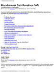
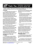
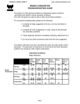
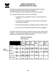
INSTALLATION
PRO HYPERCHARGER AIR CLEANER
9404
PARTS INCLUDED
1
1
Pro Hypercharger with K&N Filter
Adapter Hardware Kit Contains the Following Seventeen Items:
1
Rubber Intake Duct with Rubber Carb Bumper
1
Main Support Bracket
1
Carb Bumper Bracket
1
18” Length of 5/32” Rubber Hose
1
3-way Barbed “T” Fitting
3
1/4”–20 X 5/8” Socket Head Cap Screw
5
1/4”–20 Nylock Nut
2
1/4”–20 X 1/2” Button Socket Cap Screw
2
1/4” Flat Washer
2
Step Reducer Washer
1
90 Degree Elbow
1
6” Length of 3/8” Rubber Hose
4
Hose Clamp
2
3/8” Barbed Nylon Connector
2
M6 X 1.0 X 16mm Hex Head Cap Screw
2
M6 Flat Washer
1
Gray Vinyl Cap
1
Jet Kit Includes the Following Ten Items:
1
5/32” Drill Bit
1
# 50 Drill Bit
1
132 Main Jet
1
135 Main Jet
1
138 Main Jet
1
140 Main Jet
1
Needle
1
E-Clip
2
.020 Needle Shim
1
Slotted Pan Screw
1
Installation Instructions
Please read and understand entire instructions before starting installation.
THANK YOU FOR CHOOSING KϋRYAKYN!
IN ORDER TO PROTECT YOU AND OTHERS FROM POSSIBLE INJURY AND/OR
PROPERTY DAMAGE OR LOSS, PLEASE PAY CLOSE ATTENTION TO ALL
INSTRUCTIONS, WARNINGS, CAUTIONS AND ATTENTION NOTES REGARDING
THE USE AND CARE OF THIS PRODUCT.
WARNING!
THIS INDICATION ALERTS YOU TO THE FACT THAT IGNORING
THE CONTENTS DESCRIBED HEREIN CAN RESULT IN
POTENTIAL DEATH OR SERIOUS INJURY.
ATTENTION! This indication alerts you to the fact that ignoring the contents
described herein may negatively affect product performance and
functionality.
CAUTION!
This indication alerts you to the fact that ignoring the contents
described herein can result in potential injury or material
damage.
TOOLS SUGGESTED
Set of Metric and Standard Hex Wrenches, Set of Metric and Standard Combination Wrenches,
the Bike’s Tool Kit, Metric Socket Set, Small Vice Grip, Silicone, Phillips Screw Driver, Needle
Nose Pliers, Small Flat Tip Screwdriver, Diagonal Cutter, Drill and a Service Manual.
9404-23MC-1011
-cont.-
CUSTOMER SERVICE
877.370.3604 (toll free)
INSTALLATION QUESTIONS
[email protected]
or call 715.247.2983
LIMITED WARRANTY
Küryakyn warrants that any Küryakyn products
sold hereunder, shall be free of defects in
materials and workmanship for a period of one
(1) year from the date of purchase by the
consumer excepting the following provisions:
● Küryakyn shall have no obligation in the event
the customer is unable to provide a receipt
showing the date the customer purchased the
product(s).
●The product must be properly installed,
maintained and operated under
normal conditions.
●Küryakyn makes no warranty, expressed or
implied, with respect to any gold plated
products.
●Küryakyn shall not be liable for any
consequential and incidental damages, including
labor and paint, resulting from failure of a
Küryakyn product, failure to deliver, delay in
delivery, delivery in nonconforming condition, or
for any breech of contract or duty between
Küryakyn and a customer.
●Küryakyn products are often intended for use in
specific applications. Küryakyn makes no
warranty if a Küryakyn product is used in
applications other than intended.
●Küryakyn electrical products are warranted for
one (1) year from the date of purchase by the
consumer. L.E.D.’S contained in components of
Küryakyn products will be warranted for defects
in materials and workmanship for 3 years from
the date of purchase where as all other
components shall be warranted for one(1) year.
This includes, but is not limited to; control
modules, wiring, chrome & other components.
●Küryakyn makes no warranty of any kind in
regard to other manufacturer¹s products
distributed by Küryakyn. Küryakyn will pass on
all warranties made by the manufacturer and
where possible, will expedite the claim on behalf
of the customer, but ultimately, responsibility for
disposition of the warranty claim lies
with the manufacturer.
ABOUT OUR CATALOG
For purchasing Küryakyn® products, you
can receive a complete catalog free of charge.
Send the Proof-of-Purchase below with
your address to: Küryakyn, P.O. Box 339,
Somerset, WI 54025.
Please indicate either Accessories Catalog for
Harley-Davidson® or GL & Metric Cruisers.
Be sure to ask your local dealer about other
Küryakyn® products, the motorcycle parts and
accessories designed for riders by riders.
©2005 Küryakyn USA® All Rights reserved.
STRICTLY OBSERVE THE FOLLOWING GUIDELINES IN ORDER TO USE THE PRODUCT
PROPERLY AND AVOID POTENTIALLY DANGEROUS ACCIDENTS.
STEP 1
Read and understand all steps in the instructions before starting the installation. Park the
motorcycle on a hard, level surface and turn off the ignition. Let cool.
DISCLAIMER — PLEASE READ BEFORE PROCEEDING
Any modifications to a motorcycle’s exhaust or intake tract require carburetor re-jetting to
achieve maximum performance and maintain drivability. If you are uncomfortable with the
process of tuning your carburetor, we recommend that you bring your motorcycle to a qualified
motorcycle mechanic to have this kit installed. The jets included in this kit were selected based
on test results with various combinations of components that we felt would represent the
majority of the customers purchasing this kit. However, no two motorcycles are exactly alike.
Depending on the individual case, additional jets may need to be purchased from an outside
source. Küryakyn warrants the parts included in this kit to be free of defects in materials and
workmanship, but makes no claim whatsoever in regard to costs associated with installation or
tuning.
WARNING!
YOU WILL BE WORKING AROUND THE ENGINE AND EXHAUST SYSTEM
DURING INSTALLATION. ENSURE THAT THE ENGINE AND EXHAUST SYSTEM
HAVE FULLY COOLED TO PREVENT INJURY.
ATTENTION! A factory service manual may be helpful in performing this installation. Do not attempt
to perform this installation if you are not confident in your ability to complete all of the
steps in the procedure; consult a trained technician.
CAUTION!
The installation of any high performance exhaust system can cause a “lean”
fuel/air mixture. A “lean” fuel/air mixture can cause engine overheating
resulting in severe engine damage. Küryakyn recommends rejetting
carbureted bikes.
STEP 2
Remove the seat.
STEP 3
Remove the bottom of the three dash plaque bolts (8mm).
STEP 4
Lift up on the dash panel and unscrew the speedometer cable (knurled nut).
STEP 5
Unplug the three electrical connections.
STEP 6
With a 12mm socket, remove the tank-mounting bolt under the dash and at the rear of the tank.
STEP 7
Close the fuel valve and clamp off the fuel line. Disconnect the line from the fuel valve.
STEP 8
Raise the rear of the tank, and disconnect the two vent hoses, and remove the tank.
STEP 9
Refer to the section of your factory service manual that deals with removal and installation of the
following components:
• Remove the two round chrome “air cleaner covers”, their backing plates, the stock black plastic air box
(air inlet under tank), and the crossover tube.
• Remove the intake manifold to remove and crossover tube. Use extreme care when replacing the intake
manifold. Uneven torque, damage to the intake gaskets, or contamination can cause an intake leak that
will result in very poor running, and nearly impossible jetting!!
• Unplug all hoses or lines from these components. You may want to label these hoses at this time. The
Largest of these hoses (3/4” I.D.) is for the fresh air injection system; the second largest (3/8” I.D.) is
the crankcase breather. The smallest of the hoses is a drain.
PAGE
2
-cont.-
PRO HYPERCHARGER
INSTALLATION
STEP 10
Remove the brackets that held each round backing plate. The right hand bracket is
PIC 1
also a carb stabilizer. This function is duplicated with one of the included brackets.
STEP 11
Remove the carburetor according to the section in your factory service manual
that outlines procedures for carburetor removal, disassembly, reassembly and
installation. We recommend that you label each hose or fitting as they are re
moved to make reassembly easier. An example of hose labeling is shown in PIC.1.
LABELS
CARBURETOR RE-JETTING PROCEDURE
NOTE: Different combinations of aftermarket exhaust and air cleaners will have
FIG 1
a significant impact on carburetor jetting. The supplied jetting
components have been tested and found to be a good combination to
produce drivability and performance with stock or free flowing, muffled/
baffled exhaust pipes. We highly recommend NOT using drag pipes (open
style). Using drag pipes in conjunction with our air cleaner will require
additional jetting above and beyond the components included in this kit.
A) Consult your factory service manual for details of this procedure. We have supplied jets
to cover many common configurations. Remove the four Phillips head screws securing
the plastic carb top to the carb body. Carefully remove the plastic carb top making sure
not to damage the rubber diaphragm.
FIG 2
B) Carefully remove the diaphragm and slide from the carb.
C) Remove the spring, plastic retainer and needle from the slide.
D) See FIG.1. Very carefully drill out the slide lift hole with the included .070 drill bit. Be
sure to remove all filings from drilling. Place the small E-Clip in the third groove from
the top of the needle, See FIG.2. Stack two .020 shims on top of the E-Clip. The shims
will keep the needle from bouncing in the slide.
E) Carefully replace the needle/slide assembly into the carb body. Place the stock plastic
retainer over the end of the needle and shims. The retainer should gently seat over the
shims. Place the spring over the retainer. Carefully seat the lip of the diaphragm in the
corresponding groove in the carb body. DO NOT FOLD, PINCH, TEAR OR PUNCTURE
THE DIAPHRAGM!! Replace the top cover.
PLACE
SHIMS
HERE
FIG 3
F) READ THIS ENTIRE STEP BEFORE PROCEEDING! See FIG.3. Turn the carb upside
down. Using the supplied 5/32” drill bit, slowly drill out the plug covering the idle mixture
screw. The mixture screw is made of brass. If you drill to far you will destroy the slot in
the adjustment screw making adjustment impossible. Once the hole is drilled, start the
supplied slotted pan screw into the drilled hole just far enough for the threads to “bite”.
Grasp the head of the screw with a pliers and pull outward in a slight rocking motion until
the plug comes free.
G) Using a small flat head screwdriver, slow and gently turn the adjustment screw inward
(clock-wise) until it lightly bottoms out. Once lightly bottomed out, back the adjustment
screw outward (counter clock-wise) three full turns.
H) Remove the four Phillips head screws that secure the float bowl to the carb body. Remove the float bowl
being extremely careful no to disturb the position of the float.
I) Replace the stock low speed jet with the supplied #48 jet. Replace the stock main jet with the supplied
#135 jet.
PAGE
3
-cont.-
PRO HYPERCHARGER
INSTALLATION
CARBURETOR TUNING TIPS
PIC 2
• Run the bike until it reaches operating temperature. Adjust the idle mixture screw until
the bike reaches it’s highest idle speed. Reset the idle speed with the idle adjustment V
knob.
• If further tuning is required, let your spark plugs be your guide. A white or uncolored plug
indicates a lean condition while a black or sooty plug indicates a rich condition.
• Be sure you’re working with the correct jet. The low speed (pilot jet) affects throttle
positions of about 1/8 open to approximately 1/3 open. The main jet affects throttle
positions of about 3/4 open to wide open. Needle position affects most throttle settings in
between. In other words, don’t change the main jet if you are experiencing a lean
condition just off idle.
MAKE SURE
BOTH
FLANGES ARE
THROUGH
BRACKET
• Generally speaking, popping of backfiring through the carb indicates a lean condition.
Blubbering, smoking or popping out the exhaust indicates a rich condition.
• If you are experiencing backfiring through the exhaust, check the following before you
assume the carburetor is improperly jetted:
PIC 3
A) Leaking exhaust pipe gaskets
FLANGED END
OF RUBBER
BUMPER ON
THIS SIDE OF
BRACKET
B) Leaking fresh air system block off plate gaskets (if applicable)
C) If the fresh air system was not removed, be sure the plug has not come out of
the 3/4” inlet hose.
STEP 12
Reinstall the carburetor according to the section in your factory service manual
that outlines procedures for carburetor removal, disassembly, reassembly and
installation.
STEP 13
Insert the supplied rubber intake duct through the main support bracket making
sure both flanges are through the support bracket as shown in PIC.2.
STEP 14
Install the 90-Degree Elbow into the threaded hole in the Hyper back plate located
at the rear section (pointed end).
STEP 15
Insert the “flanged” end of the rubber carb bumper through the opening in the
center of the chrome carb bumper bracket. You will need a small flat head
screwdriver to push it through. The “knob” should protrude through the bracket in
the opposite direction as the two mounting tabs at each end of the bracket. See
PIC.3.
STEP 16
Mount the bumper bracket to the carb support bracket as shown in PIC.4, using
the 1/4–20 x 5/8” button head cap screws, reducer washers, 1/4” flat washers,
and Nylock nuts. When positioned correctly, the rubber carb bumper will be
positioned directly between the two vertical, parallel flanges on the carb body once
the assembly is mounted to the engine.
STEP 17
Remove the three fasteners that secure the front cover of the Pro Hypercharger.
Also remove the two outer most socket head caps screws that secure the bearing
caps on the top and bottom of the butterfly shaft. Remove the front cover of the
Pro Hypercharger.
STEP 18
Insert the rubber intake duct through the Hyper back plate in the same fashion it
was installed in the main support bracket. See PIC.5. You may need to use a
screwdriver to help “poke” the flange of the Rubber Intake Boot into position inside
the back plate.
PIC 4
PIC 5
PAGE
4
-cont.-
PRO HYPERCHARGER
INSTALLATION
STEP 19
See PIC.5. Roll back the inner “lip” of the rubber intake duct, align the mounting holes in the
Hyper back plate, rubber intake duct and support bracket and insert a supplied
1/4”–20 x 5/8” Socket Head Cap Screw through each hole. Secure on the bracket
PIC 6
side of the assembly with the supplied 1/4”–20 Nylock Nuts. Tighten snugly.
STEP 20
Replace the front cover of the Pro Hypercharger in reverse manner as it was re
moved in STEP 17.
STEP 21
Remove the large hose clamp from the OEM rubber air cleaner boot, (air cleaner to
carburetor connection) and install it on the carb end of the new rubber intake duct.
STEP 22
Locate the vacuum line shown in PIC.6 located at the left, front side of the carb.
Cut the vacuum line about three inches form the carb and insert the supplied
“T” fitting as shown. Connect one end of the supplied 18” hose to the remaining
outlet on the “T” fitting and route the other end downward on the forward side of
the carburetor. This end will be connected in a later step.
VACUUM LINE
“T” FITTING
TO HYPERCHARGER
STEP 23
Insert one of the supplied 3/8” double ended hose barbs into each end of the
PIC 7
supplied section of 3/8” hose and secure them in place using the supplied hose
clamps. Insert one end of the hose and barb assembly into the breather port
located at the bottom of the rubber intake duct and secure it using a supplied hose
clamp.
STEP 24
Hold the Hypercharger assembly in position. Slide the rubber intake duct over the
mouth of the carb and secure the mounting bracket to the cylinders with the M6
Hex Head bolts and flat washers provided. Tighten the hose clamp around the
mouth of the carb.
STEP 25
Route the loose end of the hose and barb assembly installed in STEP 23 to the
crank case breather hose previously connected to the OEM right side air cleaner
back plate and secure using the remaining hose clamp.
CONNECT VENT HOSE TO ELBOW ON
BACK OF HYPER
STEP 26
Connect the open end of the 1/4” hose installed in STEP 22 to the vacuum nipple
located at the bottom of the vacuum pod on the inner front portion of the hyper
back plate.
STEP 27
See PIC.7. The float bowl vent hose is connected to the left rear of the carb.
Remove this hose from the bike and cut four inches off of the end that was
previously connected to the carburetor. Reconnect the cut end of the hose to its
original location. Route the vent hose downward under the carb and connect it to
the 90 Degree Elbow that was installed in the back plate of the hyper. See STEP 14.
CAUTION!
If the float bowl vent hose is pinched or kinked your bike will not
run properly!
STEP 28
See PIC.8. Insert the supplied Gray Vinyl Cap in to the fresh air inlet hose that was
connected to the crossover tube. You may choose to spread a thin layer of silicone
inside the hose to help secure the cap inside the hose.
STEP 29
Reinstall the air box.
STEP 30
Work backwards from STEP 8 to STEP 2 to complete the installation.
STEP 31
Double check the tightness of all related fasteners, check for hose clearance and check
throttle for correct operation, making sure it returns properly, before starting the bike.
ATTENTION!
It is the installer’s responsibility to ensure that all of the fasteners (including
preassembled) are tightened before operation of the motorcycle. Küryakyn will not
warranty components lost due to improper installation. Periodic maintenance may be
required.
Ride On!
PRO HYPERCHARGER
PIC 8
GRAY VINYL CAP
PAGE
5
INSTALLATION