1
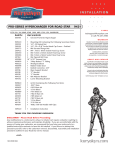
I N S TA L L AT I O N
HYPERCHARGER AIR CLEANER
9 410
F I T S : K AWA S A K I ‘ 9 5-UP VN800 VULCAN
PART #
600163
8513
8593
8562
309410
INCLUDED
1
1
1
1
1
1
1
2
3
1
2
4
1
1
1
1
1
1
1
3
1
1
2
3
1
1
1
1
1
1
1
Hypercharger — Chrome with drilled back
K&N Filter Element
Mounting Kit containing the following:
Carburetor Adapter
Carburetor Support Bracket
Breather Adapter for Vulcan 800
Gasket, Late Style with Adhesive
Gasket, Late Style
1/4”–20 x 2” SHCS with Blue Patch
1/4”–20 x 5/8” SHCS — Stainless
M6–1.0 x 16mm HHCS — Stainless
1/4” Flat Washer — Chrome
16” Length 5/32” Vacuum Hose
6” Length 3/8” Hose
Mini Three-Way Tee
1/8” NPT Nipple
3/8” Connector, Barbed
Cap .562 ID X .69 OD X 1⁄2”
Male 1/8”–27 Threaded 90° Elbow
Hose Clamps — Stainless
Jet Kit for VN800 Including the Following:
Fuel Injection Needle
E Clip for Fuel Needle
.020 Needle Shim
5/32” Drill Bit
12 X 3/4” Slotted Pan Screw
#160 Main Jet
#165 Main Jet
#170 Main Jet
#180 Main Jet
Installation Instructions
THANK YOU FOR CHOOSING KÜRYAKYN!
WARNING
Gasoline is extremely flammable. To reduce the possibility of harmful or fatal fire from
accidental ignition of fuel from the tank, we suggest disconnecting the battery cables from
the battery before beginning this install. Use good judgment and do not smoke.
-cont.-
9410-12HD-0705
CUSTOMER SERVICE
877.370.3604 (toll free)
INSTALLATION QUESTIONS
[email protected]
or call 715.247.2983
LIMITED WARRANTY
Küryakyn warrants that any Küryakyn products sold
hereunder, shall be free of defects in materials and
workmanship for a period of one (1) year from the
date of purchase by the consumer excepting the
following provisions:
• Küryakyn shall have no obligation in the event
the customer is unable to provide a receipt showing
the date the customer purchased the product(s).
• The product must be properly installed,
maintained and operated under normal conditions.
• Küryakyn makes no warranty, expressed or
implied, with respect to any gold plated products.
• Küryakyn shall not be liable for any consequential
and incidental damages, including labor and
paint, resulting from failure of a Küryakyn product,
failure to deliver, delay in delivery, delivery in nonconforming condition, or for any breech of contract or
duty between Küryakyn and a customer.
• Küryakyn products are often intended for use
in specific applications. Küryakyn makes no
warranty if a Küryakyn product is used in
applications other than intended.
• Küryakyn electrical products are warranted for one
(1) year from the date of purchase by the consumer.
Components of Küryakyn products containing L.E.D.s
will be warranted for defects in materials and
workmanship for 3 years from the date of purchase.
• Küryakyn makes no warranty of any kind in regard
to other manufacturer’s products distributed by
Küryakyn. Küryakyn will pass on all warranties made
by the manufacturer and where possible, will expedite the claim on behalf of the customer,
but ultimately, responsibility for disposition of the
warranty claim lies with the manufacturer.
ABOUT OUR CATALOG
You’ll find all our innovations for H-D, GL and
Metric Cruisers in our annual catalogs. Order online
today–select the ”CATALOGS” icon. Each Küryakyn™
product comes with a Proof-of-Purchase good for a
complimentary catalog. Details in packaging.
Be sure to ask your local dealer about other
Küryakyn products, the motorcycle parts and accessories designed for riders by riders.
©2005 Küryakyn USA™ All Rights reserved.
DISCLAIMER – PLEASE READ BEFORE PROCEEDING:
Any modifications to a motorcycle’s exhaust or intake tract require carburetor re-jetting to achieve
maximum performance and maintain drivability. If you are uncomfortable with the process of tuning
your carburetor, we recommend that you bring your motorcycle to a qualified motorcycle mechanic
to have this kit installed. The jets included in this kit were selected based on test results with
various combinations of components that we felt would represent the majority of the customers
purchasing this kit. However, no two motorcycles are exactly alike. Depending on the individual
case, additional jets may need to be purchased from an outside source. Kuryakyn warrants the
parts included in this kit to be free of defects in materials and workmanship, but makes no claim
whatsoever in regard to costs associated with installation or tuning.
PIC.1
NOTE
Please read each step of the instruction carefully before proceeding with the installation. Refer
to your factory service manual during this installation as needed.
PROCEDURE
PIC.2
STEP 1 Remove the seat from the motorcycle.
STEP 2 Remove the dash from the fuel tank. You will have to unplug two plugs, and unscrew
the speedometer cable from the speedometer head.
STEP 3 Make sure the fuel petcock is closed. Remove the fuel line and vacuum line from
the petcock and the vent hoses from the fuel tank. Remove the fuel tank mounting bolts and
remove the tank from the motorcycle.
STEP 4 Remove the air box from the bike. See PIC.1.
PIC.3
STEP 5 Remove the chrome air cleaner cover, filter, and backing plate from the bike. See
PIC.2.
STEP 6 Remove the hoses shown in PIC.3 from the rear of the stock air cleaner. Insert the
vinyl cap onto the end of the largest hose (fresh air induction).
STEP 7 Remove the stock air cleaner support bracket. Set it and its fasteners aside as they
will be reused. See PIC.4.
STEP 8 Using a 3mm Allen wrench, loosen the clamp that secures the carb spigot to the
PIC.4
intake manifold.
STEP 9 See PIC.5. Remove the vacuum line, float bowl vent, fuel line, throttle control cables,
and enrichener control from the carburetor.
STEP 10 Pull the carb free of the manifold and remove it from the motorcycle. Install the Jet
Kit provided.
Now is a good time to proceed with re-jetting the
carburetor. Consult your factory service manual for details
of this procedure. We have supplied jets to cover many
common configurations.
PIC.5
-cont.PAGE
2
HYPERCHARGER AIR CLEANER
INSTALLATION
CARBURETOR RE-JETTING PROCEDURE
NOTE
Different combinations of aftermarket exhaust and air cleaners will have a significant
impact on carburetor jetting. The supplied jetting components have been tested and found to be
a good combination to produce drivability and performance with stock or free flowing, muffled/
baffled exhaust pipes. We highly recommend NOT using drag pipes (open style). Using drag pipes in
conjunction with our air cleaner may require additional jetting above and beyond the components
included in this kit.
A) Carefully drain all gas from the carburetor.
B) See FIG.1. Set the carburetor on its top with the float bowl facing upwards.
FIG.1
Observe the cylindrical casting to the rear of the float bowl. Notice the brass plug in
the end of that casting. Use a center punch to make a divot in the end of this plug.
Using the supplied drill bit carefully drill out the center of the plug. IMPORTANT:
Located below the plug is a brass adjustment screw. Be extremely careful not to
allow the drill bit to break through the plug and damage the screw below. Start the
supplied slotted pan screw into the hole you drilled and thread it in just enough for
the threads to bite. Grasp the screw with pliers and gently wiggle the screw back
and fourth while pulling outward to remove the plug. Turn the adjustment screw all
the way in until it lightly bottoms out. Back the adjustment screw out 3-1/2 turns
from bottomed.
C) Carefully remove the float bowl. The stock #48 low speed jet is located in the
deep cylindrical recess. Remove and replace the main jet with one of the following...
#160 – Used in high elevations and/or with stock or restrictive exhaust
#165 – Used with baffled drag pipes (like the Vance & Hines Straight Shots)
#170 – Muffled performance pipes (like Cobra or Vance & Hines Duals)
#180 – Open drag pipes
D) Replace the float bowl.
E) Carefully remove the carburetor top, slide spring, and slide. The rubber diaphragm is very fragile.
Use caution not to tear, puncture or stretch it. The needle can be addressed one of two ways.
1) The stock needle works well when installed with the three supplied needle shims placed
under the head of the needle, raising the installed position of the needle.
2) The supplied needle may also be installed providing further adjustment if additional
performance modifications will be made.
F) Once your choice of needle has been installed, Replace the nylon needle retainer, slide, and slide
spring.
G) Carefully place the lip of the diaphragm into the groove in the top of the carburetor body and
install the carburetor top. IMPORTANT: Be sure the diaphragm has not been pinched or damaged
in any way during installation. ANY leak in this seal will cause the bike to run poorly and will require
replacement of the diaphragm.
CARBURETOR TUNING TIPS
Several factors can influence the tuning and drivability of your motorcycle. Altitude, temperature,
and choice of exhaust will all affect performance. Further adjustments may be required based
on these factors. Backfires through the intake generally indicate a lean condition. Blubbering,
shuddering, smoking and plug fowling indicate a rich condition. If jet changes are required be certain
that you change the jet causing the problem. EXAMPLE: If your bike exhibits a cough or backfire
through the intake, changing the main jet would not change the condition.
PAGE
• From idle to 1/8 throttle is controlled by the idle mixture screw
• Just off idle to 1/4 throttle is controlled by the low speed jet
• 1/4 throttle to 3/4 throttle is controlled by the needle and needle jet
• 3/4 throttle to wide open is controlled by the main jet
3
-cont.-
HYPERCHARGER AIR CLEANER
INSTALLATION
STEP 11 Reinstall the carb on the manifold, and re-connect all hoses, cables etc. Tighten the intake
manifold clamp.
STEP 12 Reinstall the stock carb support bracket.
PIC.6
STEP 13 Install the billet aluminum carburetor adapter on the mouth of the carburetor.
The adapter’s slot should be in the 3 o’clock position with the pinch bolt installed from
the top. Do not tighten the pinch bolt at this time. Install the peel and stick gasket to the
exposed surface of the adapter.
STEP 14 Install the chrome carb support bracket using the M6-1.0 x 15mm hex head cap
screws provided. (PIC.6). If there is a gap between the stock air cleaner mounting bracket
and the new carb support, shim with the supplied 1/4” flat washers. In some cases it may
be necessary to slightly bend the stock bracket so the carb support will lay flat against the
adapter when the M6 screws are tightened.
PIC.7
STEP 15 Install the 1/8” NPT x 3/8” O.D. nipple in the threaded hole in the bottom of the
breather adapter.
STEP 16 Remove the trap door from the front with a 1/8” hex key, remove the trap
door on the front of the Hypercharger. Install the Hypercharger and breather adapter
as one unit. The three 1/4”–20 x 2” socket head cap screws will go through the back of
the Hypercharger, the breather adapter, and the carb support then thread into the carb
adapter. Be sure to install gaskets between the Hypercharger and breather adapter and
the breather adapter and support bracket. The breather nipple should point downward.
Note that one of the four holes in the Hypercharger will not be used - it is a vent hole for
H-D applications. See PIC.7 (In PIC.7 we have removed the front of the Hypercharger and
the filter for clarity. You need only remove the trap door.) Adjust the Hypercharger so it is
horizontal before tightening the 1/4”–20 x 2” screws. Reinstall the trap door and securely
tighten the adapter pinch bolt.
PIC.8
STEP 17 Insert the 3/8” barbed connector into the breather hose (PIC.3) and add the
6” length of 3/8” I.D. hose included in the kit. Plug the extended breather hose onto the
breather adapter’s nipple. Secure all connections with the hose clamps provided (PIC.8).
STEP 18 VERY IMPORTANT! Install the plastic 90° elbow in the threaded hole on the
back of the Hypercharger. The stock float bowl vent hose is routed from the carb back to
a “dead end” location under the seat. Pull this hose free from under the seat, but leave it
connected to the carb fitting. Run this hose from the carb down to the 90° fitting on the
back of the Hypercharger, cut it to length, and connect it to the fitting. See PIC.9.
PIC.9
STEP 19 See PIC.10. Locate the vacuum line going to the fuel petcock. At a convenient
location, cut the line and install the “T” as shown. Install the supplied length of vacuum
hose to the “T” and connect the remaining end to the vacuum nipple on the bottom of the
Hypercharger. (The butterflies will be wide open when the bike is off, or at full throttle, and
mostly closed when the bike is at idle.
STEP 20 Re-install the tank, dash, and seat in the
PIC.10
same manner it was removed.
NOTE
Before starting engine check all fasteners to
make sure they are tight. Check all hoses to make sure
they are connected and not kinked. Check throttle
operation to make sure it operates freely.
Ride On!
PAGE
4
HYPERCHARGER AIR CLEANER
INSTALLATION
HYPER
PAGE
5
HYPERCHARGER AIR CLEANER
INSTALLATION