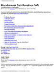
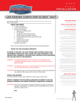
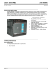
1
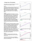
INSTALLATION
PRO R HYPERCHARGER for YAMAHA
9463
PARTS INCLUDED
1
5
Pro R Hypercharger Assembly Including The Following Items:
Screws in Plastic Bag Including:
3
1/4”-20 X 1-5/8” Button Socket Cap Screws
2
#6-32 X 3/8” Socket Head Cap Screws
2
#6 Flat Washers—NOT USED
1
Dual Velocity Ring—NOT USED
1
Filter Cage Assembly 3-PC.
1
Hyper Filter Round
1
1100 V-Star Bracket/Manifold Hardware Kit:
1
Ribbed Rubber Hyper Duct
1
Internal Duct Support, Black Plastic
1
Steel Chrome Bracket
1
Hardware Kit Including The Following:
3
M6 Aluminum Tapered bolt Cap
3
M6 x 1.0 x 16mm Socket Head Cap Screw
1
M6 Flange Nut
1
Step (Reducer) Washer
3
1/4”-20 x 5/8” Socket Head Cap Screw
3
1/4”-20 Flange Nuts
1
12” Length of Vacuum Hose
8
M4 x 10mm Socket Head Cap Screw
1
90 Degree Elbow
2
.020” Thick Needle Shim
1
Galvanized Clamp Hook
1
Jet Kit Includes the Following Four Items:
1
125 Main jet
2
1.2 Pilot Air Bleed
1
120 Main Jet
1
122.5 Main Jet
1
Installation Instructions
Please read and understand entire instructions before starting installation.
THANK YOU FOR CHOOSING KϋRYAKYN!
IN ORDER TO PROTECT YOU AND OTHERS FROM POSSIBLE INJURY AND/OR
PROPERTY DAMAGE OR LOSS, PLEASE PAY CLOSE ATTENTION TO ALL
INSTRUCTIONS, WARNINGS, CAUTIONS AND ATTENTION NOTES REGARDING
THE USE AND CARE OF THIS PRODUCT.
WARNING!
THIS INDICATION ALERTS YOU TO THE FACT THAT IGNORING
THE CONTENTS DESCRIBED HEREIN CAN RESULT IN
POTENTIAL DEATH OR SERIOUS INJURY.
ATTENTION! This indication alerts you to the fact that ignoring the contents
described herein may negatively affect product performance and
functionality.
CAUTION!
This indication alerts you to the fact that ignoring the contents
described herein can result in potential injury or material
damage.
TOOLS SUGGESTED
Set of Metric and Standard Hex Wrenches, Set of Metric Combination Wrenches, Phillips
Screwdriver
9463-24MC-1011
-cont.-
CUSTOMER SERVICE
877.370.3604 (toll free)
INSTALLATION QUESTIONS
[email protected]
or call 715.247.2983
LIMITED WARRANTY
Küryakyn warrants that any Küryakyn products
sold hereunder, shall be free of defects in
materials and workmanship for a period of one
(1) year from the date of purchase by the
consumer excepting the following provisions:
● Küryakyn shall have no obligation in the event
the customer is unable to provide a receipt
showing the date the customer purchased the
product(s).
●The product must be properly installed,
maintained and operated under
normal conditions.
●Küryakyn makes no warranty, expressed or
implied, with respect to any gold plated
products.
●Küryakyn shall not be liable for any
consequential and incidental damages, including
labor and paint, resulting from failure of a
Küryakyn product, failure to deliver, delay in
delivery, delivery in nonconforming condition, or
for any breech of contract or duty between
Küryakyn and a customer.
●Küryakyn products are often intended for use in
specific applications. Küryakyn makes no
warranty if a Küryakyn product is used in
applications other than intended.
●Küryakyn electrical products are warranted for
one (1) year from the date of purchase by the
consumer. L.E.D.’S contained in components of
Küryakyn products will be warranted for defects
in materials and workmanship for 3 years from
the date of purchase where as all other
components shall be warranted for one(1) year.
This includes, but is not limited to; control
modules, wiring, chrome & other components.
●Küryakyn makes no warranty of any kind in
regard to other manufacturer¹s products
distributed by Küryakyn. Küryakyn will pass on
all warranties made by the manufacturer and
where possible, will expedite the claim on behalf
of the customer, but ultimately, responsibility for
disposition of the warranty claim lies
with the manufacturer.
ABOUT OUR CATALOG
For purchasing Küryakyn® products, you
can receive a complete catalog free of charge.
Send the Proof-of-Purchase below with
your address to: Küryakyn, P.O. Box 339,
Somerset, WI 54025.
Please indicate either Accessories Catalog for
Harley-Davidson® or GL & Metric Cruisers.
Be sure to ask your local dealer about other
Küryakyn® products, the motorcycle parts and
accessories designed for riders by riders.
©2005 Küryakyn USA® All Rights reserved.
STRICTLY OBSERVE THE FOLLOWING GUIDELINES IN ORDER TO USE THE PRODUCT
PROPERLY AND AVOID POTENTIALLY DANGEROUS ACCIDENTS.
STEP 1
Read and understand all steps in the instructions before starting the installation. Park the
motorcycle on a hard, level surface and turn off the ignition. Let cool.
DISCLAIMER — PLEASE READ BEFORE PROCEEDING
Any modifications to a motorcycle’s exhaust or intake tract require carburetor re-jetting to
achieve maximum performance and maintain drivability. If you are uncomfortable with the
process of tuning your carburetor, we recommend that you bring your motorcycle to a qualified
motorcycle mechanic to have this kit installed. The jets included in this kit were selected based
on test results with various combinations of components that we felt would represent the
majority of the customers purchasing this kit (see Addendum I). However, no two motorcycles
are exactly alike. Depending on the individual case, additional jets may need to be purchased
from an outside source. Küryakyn warrants the parts included in this kit to be free of defects in
materials and workmanship, but makes no claim whatsoever in regard to costs associated with
installation or tuning.
WARNING!
YOU WILL BE WORKING AROUND THE ENGINE AND EXHAUST SYSTEM
DURING INSTALLATION. ENSURE THAT THE ENGINE AND EXHAUST SYSTEM
HAVE FULLY COOLED TO PREVENT INJURY.
ATTENTION! A factory service manual may be helpful in performing this installation. Do
not attempt to perform this installation if you are not confident in your
ability to complete all of the steps in the procedure; consult a trained
technician.
CAUTION!
PIC 1
The installation of any high performance exhaust system can
cause a “lean” fuel/air mixture. A “lean” fuel/air mixture can
cause engine overheating resulting in severe engine damage.
Küryakyn recommends rejetting carbureted bikes.
REMOVE THIS GROMMET
NOTE: This installation requires re-jetting of the carburetors. This is an involved
procedure that we recommend be performed by a qualified service
technician. If you choose to attempt this procedure yourself, refer to the
carburetor removal, disassembly, reassembly, and installation procedures
outlined in your V-Star service manual.
STEP 2
Remove the driver and passenger seats from the bike. Remove the negative
battery cable from the battery and tuck it out of the way to reduce the possibility
of sparks.
STEP 3
Remove the two, rear tank mounting bolts. Remove the plastic tank mounting
snap stud. (Push in on the center of it to release). Slide the tank back to expose
the top of the engine. Make sure the tank is secured so it does not fall! You may
remove the tank completely if so desired.
STEP 4
Remove the stock air cleaner cover, element, and backing plate. The top and rear
mounts are secured with screws, the front mount “snaps” into a grommet.
STEP 5
See PIC.1 and PIC.2. Remove the grommet from the bracket.
STEP 6
Placing your long handled Phillips screwdriver as shown in PIC.3, loosen the clamp
on the air duct and remove the duct. Remove the clamp from the duct and set it
aside, as it will be reused.
PIC 2
PIC 3
NOTE: Now is a good time to proceed with re-jetting of the carburetors. Consult
your factory service manual for this procedure. We have supplied jets to
cover most common applications.
LOOSEN THIS CLAMP
PAGE
2
-cont.-
PRO R HYPERCHARGER
INSTALLATION
Jetting Recommendations: See FIG.1 for jet locations.
With stock exhaust or Cobra Slip-On Mufflers
•
•
•
•
•
FIG 1
1.2 Pilot Air Bleeds in both carbs
One .020 shim added to raise each needle
122.5 Main Jet in the front cylinder’s carb
120 Main Jet in the rear cylinder’s carb
Pilot Mixture Screw (PMS) 2 turns out from lightly
bottomed
With Vance & Hines, Samson, or open “Drag”
pipes
•
•
•
•
•
1.2 Pilot Air Bleeds in both carbs
One .020 shim added to raise each needle
125 Main Jet in the front cylinder’s carb
122.5 Main Jet in the rear cylinder’s carb
Pilot Mixture Screw (PMS) 2 turns out from lightly
bottomed
NOTES:
A)
The factory installed plug covering the PMS will
have to be removed in order to access the screw.
B)
Because the float bowl screws are easily damage
during removal, we have included 8 replacement
float bowl screws with socket heads, just in case
they are needed.
BE SURE TO VENT THE FLOAT BOWLS TO THE
BACK OF THE HYPERCHARGER — THIS IS
NECESSARY FOR BEST DRIVABILITY AND
MAXIMUM PERFORMANCE!!!! (See STEP 16.)
STEP 7
STEP 8
See PIC.4. Insert both flanges of the rubber air
duct through the opening in the mounting
bracket. Place the galvanized clamp hook on
the duct clamp as shown in PIC.4A. You will need to flatten this hook on the
clamp. Place the Stock duct clamp on the new intake duct — the clamp screw
should face forward. See PIC.4B.
PIC 4
Install the mounting bracket and duct assembly using the supplied
M6 x 1.25 x 15mm socket heads and tapered socket head bolt caps. The front
mounting point will also use the step (reducer) washer and M6 flange nut. Make
sure the intake duct is in position on the air box inlet. Tighten the bracket
securely, but leave the clamp on the intake duct loose for now. See PIC.5.
PIC 4B
PIC 4A
SCREW FACES FORWARD
PAGE
3
-cont.-
PRO R HYPERCHARGER
INSTALLATION
STEP 9
Loosen the clamps securing the stock rubber elbows to the carburetors and air box. Gently wiggle
the air box to ensure that the rubber intake duct is fully seated on the air box inlet
PIC 5
(removing the air box lid makes it much easier to see if it is on completely). Once
everything is situated and comfortably in place, tighten the clamp on the rubber
intake duct first and then tighten the clamps on the stock rubber elbows. Replace
the air box lid.
STEP 10
Remove the front cover of the Pro-R Hypercharger.
STEP 11
Wet the radius portion of the intake duct with soapy water solution and slide the
back plate of the Hypercharger into place on the intake assembly. It should be
between the two rubber flanges on the intake duct.
STEP 12
Install the 5/16” Barb x 1/8” NPT Right Angle Fitting in the back of the
Hypercharger.
USE REDUCER WASHER
AND M6 HEX NUT BEHIND
THIS FASTENER
PIC 6
STEP 13
Using the 1/4”–20 x 5/8” socket heads and flanged nuts, bolt the Hypercharger
back half into place. See PIC.6. It is helpful to fold a portion of the radius back
while performing this procedure.
STEP 14
Install the K&N filter and the Filter Cage Assembly. Replace the front cover of
the Pro-R Hypercharger fastening with the supplied fasteners in the bag in the
Hyper. Install the 2 small screws into the Pro R end caps without using the
washers. Tighten all Screws.
STEP 15
See PIC.7. This is the vacuum nipple in the front carb. Connect the supplied
vacuum hose to this nipple, and connect the remaining end to the vacuum nipple
on the bottom of the Hypercharger.
STEP 16
IMPORTANT See PIC.8, PIC.9, and PIC.10. This is the float bowl vent hose.
PIC 7
Connect this hose to the black right angle fitting on the back of the Hypercharger.
STEP 17
Replace the fuel tank and re-connect the positive battery cable, re-install seats.
STEP 18
Double check the tightness of all related fasteners, check for hose
clearance and check throttle for correct operation, making sure it returns properly,
before starting the bike.
ATTENTION!
VACUUM NIPPLE
It is the installer’s responsibility to ensure that all of the fasteners (including
preassembled) are tightened before operation of the motorcycle. Küryakyn will not
warranty components lost due to improper installation. Periodic maintenance
may be required.
PIC 8
VENT HOSE
ATTENTION! Some of our high performance air cleaners extend beyond the stock/OEM unit to
achieve smoother air flow and better performance. Riding position may be
affected.
PIC 10
PIC 9
ROUTE TOWARDS
REAR OF BIKE
ATTACH TO ELBOW
ON THE BACK OF
HYPERCHARGER
PAGE
4
Ride On!
PRO R HYPERCHARGER
INSTALLATION