1
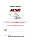
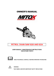
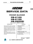
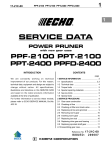
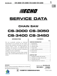
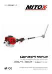
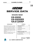
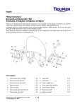
1
SRM-510ES
10-52F-01
1
SERVICE DATA
TRIMMER/BRUSHCUTTER
SRM-510ES
(Serial number : 36000001 and after)
INTRODUCTION
We are constantly working on technical improvement of our products. For this reason,
technical data, equipment and design are
subject to change without notice. All specifications, illustrations and directions in this
SERVICE DATA are based on the latest
product information available at the time of
publication.
ECHO SERVICE MANUAL Ord. 402-25
(Model : SRM-4000, RM-4000) contains lots
of information for servicing this model.
CONTENTS
page
1 SERVICE INFORMATION .............................. 2
1-1 Specification ............................................... 2
1-2 Technical data ............................................. 3
1-3 Torque limits................................................ 4
1-4 Special repairing materials ......................... 4
1-5 Service limits............................................... 5
1-6 Special tools ............................................... 6
2 CARBURETTOR ADJUSTMENT PROCEDURE .. 7
2-1 General adjusting rules ............................... 7
2-2 Presetting Idle adjust screw, Idle mixture
needle and Hi speed mixture needle .................... 7
2-3 Adjusting carburettor................................... 8
Reference No. 10-52F-01
REVISED:
201002
ISSUED: 200906
2
SERVICE INFORMATION
SRM-510ES
1 SERVICE INFORMATION
1-1 Specifications
Model
Dimensions* Length
Width
Height
Dry weight*
Engine
Type
Rotation
Displacement
Carburettor
Ignition
Starter
Fuel
Clutch
Handle
SRM-510ES (L)
mm(in)
mm(in)
mm(in)
kg(lb)
cm3(in3)
Bore
mm(in)
Stroke
mm(in)
Compression ratio
Type
Model
Venturi size -Throttle bore mm(in)
Metering diaphragm pressure
Type
SRM-510ES (U)
1860 (73.2)
355 (14.0)
655 (25.8)
324 (12.8)
460 (18.1)
8.5 (18.7)
8.8 (19.3)
KIORITZ, air-cooled, two-stroke, single cylinder
Anticlockwise as viewed from the output end
51.7 (3.155)
44.0 (1.732)
34.0 (1.339)
5.8
Rotary type : Diaphragm, horizontal-draught, with primer†
Walbro WYK-341
13.5 - 15.0 (0.531 - 0.591)
Lead pressure from inside of cleaner case
CDI (Capacitor discharge ignition) system
Digital magneto
RCJ-6Y, BPRM7A
ES (effortless-start)
3.8 x 1150 (0.15 x 45.3)
Premixed two-stroke fuel
50 : 1 (2 %)
Minimum 89 octane petrol (RON)
ISO-L-EGD (ISO/CD13738), JASO FC/FD
1.0 (33.8)
Centrifugal, 2 - shoe pivot
Spark plug
Type
Rope diameter x length mm(in)
Type
Mixture ratio
Petrol
Two-stroke air cooled engine oil
Tank capacity
L (U.S.fl.oz.)
Type
Front : Crescent loop with cushion grip
Type
Rear : Integrated control grip with cushion
Drive shaft
Type
Inner shaft: Diameter - Length
Gear case
Cutter
mm(in)
U-handle
with integratedcontrol grip
Solid, hollow type with serration (10-tooth)
8 - 1588 (0.31 - 62.5)
28 - 24 (1.10 -0.94)
1530 (60.2)
1.33
Spiral bevel gear
Housing
OD -ID mm(in)
(Main pipe)
Length mm(in)
Reduction ratio
Gear tooth
Lithium based grease or ECHO XTended Protection TM Lubricant
Lubrication
Type
Nylon line cutter
3-tooth blade (255mm)
Pilot diameter
mm(in)
25.4 (1.0)
Fastener type, size
mm
Left-hand thread nut, M10 x 1.25 pitch
Cutting rotation
Anticlockwise as viewed from top
OD: Outer diameter.
* Without shoulder harness and standard cutter.
†
Primer is on cleaner case.
ID: Inner diameter.
SRM-510ES
1-2 Technical data
Model
Engine
Idling speed
Operating speed
Wide open throttle speed
3
SERVICE INFORMATION
SRM-510ES (L)
r/min
r/min
r/min
Clutch engagement speed
r/min
†
Service limit speed
r/min
Compression pressure
MPa (kgf/cm2 ) (psi)
Ignition system
Spark plug gap
mm(in)
Minimum secondary voltage at 1000 r/min
kV
Secondary coil resistance
kΩ
Pole shoe air gaps
mm(in)
Ignition timing
at 1,000 r/min
°BTDC
at 3,000 r/min
°BTDC
at 8,000 r/min
°BTDC
at 10,000 r/min °BTDC
PET-9000 Parameter #1
#2
Carburettor
Idle adjust screw initial setting
turns in**
Idle mixture needle initial setting
turns in***
Hi speed mixture needle initial setting
turns out
Test Pressure, minimum
MPa (kgf/cm2) (psi)
Metering lever height
mm(in)
Air cleaner system
type
Air filter
SRM-510ES (U)
2,750 +/- 250
8,000
9,500 - 11,000*1
11,000 - 11,700*2
3,500
3,300
0.83 (8.5) (121)
0.6 - 0.7 (0.024 - 0.028)
14.0
2.0 - 2.8
0.30 - 0.40 (0.012 - 0.016)
22
15
25
25
328
05
1 1/2
13
3 3/4
0.05 (0.5) (7.0)
1.5 (0.06) lower than diaphragm seat
Inner vent
Pleats
BTDC: Before top dead centre.
1
2
* With Nylon line cutter and shield.* With 3-tooth blade (255 mm).
** Set idle adjust screw to the point that its tip just contacts throttle plate before initial setting.
*** Screw in idle mixture needle from initial thread engagement (at the point that the clicking sound is heard).
†
If clutch engagement speed is lower than service limit speed, replace clutch assembly with new one.
4
SERVICE INFORMATION
1-3 Torque limits
Descriptions
Starter Starter pulley
system Starter case
Ignition Magneto rotor (Flywheel)
system Ignition coil
Spark plug
Fan cover
Fuel
Carburettor insulator
system Carburettor
Fuel tank bracket
Fuel tank
Clutch Clutch shoe
Engine Crankcase
Cylinder
Top guard
Muffler
Muffler cover
Muffler stay
Others Blade fastening nut
Regular bolt, nut and screw
Size
M8
M 5*
M 10
M5
M 14
M5
M5
M5
M5
M 5*
M8
M 5**
M 5**
M 5*
M6
M 5*
M5
LM 10
M3
M4
M5
M6
M8
M 10
kgf•cm
180 - 220
35 - 50
200 - 240
60 - 100
130 - 170
50 - 90
40 - 55
30 - 45
70 - 110
50 - 90
160 - 200
70 - 110
70 - 110
30 - 45
110 - 150
30 - 45
70 - 110
280 - 320
6 - 10
15 - 25
25 - 45
45 - 75
110 - 150
210 - 300
SRM-510ES
N•m
18 - 22
3.5 - 5
20 - 24
6 - 10
13 - 17
5-9
4 - 5.5
3 - 4.5
7 - 11
5-9
16 - 20
7 - 11
7 - 11
3 - 4.5
11 - 15
3 - 4.5
7 - 11
28 - 32
0.6 - 1
1.5 - 2.5
2.5 - 4.5
4.5 - 7.5
11 - 15
21 - 30
in•lbf
160 - 190
30 - 45
175 - 210
50 - 90
115 - 150
45 - 80
35 - 50
26 - 40
60 - 95
45 - 80
140 - 175
60 - 95
60 - 95
26 - 40
95 - 130
26 - 40
60 - 95
245 - 280
5-9
13 - 22
22 - 40
40 - 65
95 - 130
180 - 260
LM: Left hand thread.
* Apply thread locking sealant. (See below)
** The torque differences among four bolts should not exceed 20 kgf•cm (2N•m, 17in•lbf) on one cylinder or
crankcase.
1-4 Special repairing materials
Material
Location
Grease
Gear case
Rewind spring
Oil
Thread locking sealant
Starter center post
Oil seal inner lips
Drive shaft
Starter case
Muffler cover
Fuel tank
Top guard
Remarks
Lithium based grease or ECHO XTended Protection TM
Lubricant
Two-stroke engine oil or engine oil (SAE#30)
Loctite #242, ThreeBond #1324 or equivalent
SRM-510ES
5
SERVICE INFORMATION
1-5 Service limits
A
B
C
D
5K222
5K223
5K224
E
F
G
H
5K225
5K016
5K042
K
L
M
5K219
5K220
5K189
5K245
5K246
mm (in)
Description
A Cylinder bore
B Piston outer diameter
C Piston pin bore
When plating is worn and aluminum can be seen
Min.
43. 95 (1.730)
Max.
10. 035 (0.3951)
D Piston ring groove
Max.
1. 65 (0.065)
E Piston ring side clearance
Max.
0. 1
F Piston pin outer diameter
Min.
13. 97 (0.5500)
G Piston ring width
Min.
1. 45 (0.057)
0. 5
(0.004)
H Piston ring end gap
Max.
K Con-rod small end bore
Max.
14. 025 (0.5522)
L Crankshaft runout
Max.
0. 02 (0.001)
M Clutch drum bore
Max.
79. 5
(0.02)
(3.13)
6
SERVICE INFORMATION
SRM-510ES
1-6 Special tools
2: a = 4 mm
3: a = 5 mm
5
6
7
4
0.
P
E
3
T3
1.
1.
65
4
04
1
1.
5
a
9: a = 80 mm
8
12
11
10: a = 70 mm
a
13
a
15: a = 12 mm
14
17
18
25
26
20
19
b = 32 mm
EC
HO
16: a = 15 mm
b = 24.5mm
b
21
22
23
27
50
0.4
0
0.8
0
1.2
Description
Tachometer PET-304
L-hex wrench (4 mm)
L-hex wrench (5 mm)
Puller
Pressure connector
Piston stopper
Metering lever gauge
PTO shaft puller
Bearing wedge
Bearing wedge
Bearing tool
Piston pin tool
2-pin wrench
Oil seal tool
Oil seal tool
Oil seal tool
Bearing tool
Piston holder
Washer
Limiter plug tool
Spark tester
Pressure tester
Pressure plug
Pressure plate
Pressure plug
Compression gauge
Ignition Analyzer : PET-9000
a
Part Number
G310-000050
895610-79920
895611-79920
897501-03938
897835-16131
897537-30130
897563-19830
897603-23030
897701-02830
897701-06030
897701-14732
897702-30131
897712-04630
897714-12330
897714-24330
897726-21430
897718-03930
897719-02830
363018-00310
91020
897800-79931
897803-30132
897826-16131
897827-16131
897831-16131
91037
900300
PET-9000
OPPAMA
INTEGRATED IGNITION ANALYZER
1.
Key
1
2
3
4
5
6
7
8
9
10
11
12
13
14
15
16
17
18
19
20
21
22
23
24
25
26
27
MP
24
Used for:
Measuring engine speed to adjust carburettor
Removing and installing hex. socket bolt (M5)
Removing and installing hex. socket bolt (M6)
Removing flywheel
Testing crankcase and cylinder leakages
Locking crankshaft rotation
Measuring metering lever height on carburettor
Removing PTO shaft
Removing ball bearing remaining on crankshaft
Removing ball bearing on PTO shaft / drive gear
Removing and installing ball bearings on crankcase / clutch drum
Removing and installing piston pin (Use 10mm dia. adapter)
Removing and installing pawl carrier
Installing crankcase oil seal (clutch side)
Installing crankcase oil seal (starter side) / PTO shaft bearings
Installing crankcase oil seal (clutch side)
Installing crankcase oil seal (starter side)
Making piston steady to remove and install piston / ring
Installing crankcase oil seal (starter side)
Removing and installing limiter plug
Checking ignition system
Testing fuel pipes/tank and crankcase leakages
Plugging intake port to test crankcase / cylinder sealing
Plugging intake port to test crankcase / cylinder sealing
Plugging exhaust port to test crankcase / cylinder sealing
Measuring cylinder compression
Measuring Ignition timing, Primary/Secondary voltage engine speed
SRM-510ES
SERVICE INFORMATION
7
2 CARBURETTOR ADJUSTMENT PROCEDURE
2-1 General adjusting rules
A. Before adjustment, check the following items.
1. The correct spark plug must be clean and properly gapped.
2. The air filter element must be clean and properly installed.
3. The muffler exhaust port must be clear of carbon.
4. The fuel lines, tank vent and fuel filter are in good condition and clear of debris.
5. The fuel is fresh ( > 89 octane : RON ) and properly mixed at 50 : 1 with “ISO L-EGD” or “JASO FC/FD” 2-stroke oil.
6. Install nylon line cutter with 2 nylon lines (225 mm) properly cut without shield, even if 3-tooth blade is
installed, for proper engine loading to adjust carburettor on both SRM-510ES(L) and SRM-510ES(U).
B. Adjustment with limiter plugs on carburettor.
Start and run engine for 10 seconds at idle, and for 2 minutes alternating engine speed between WOT for
20 seconds and Idle for 10 seconds. Adjust idle engine speed to 2,800 +/- 200 r/min by turning Idle adjust
screw. Adjust nylon line length to be WOT engine speed within 8,000 +/- 500 r/min (10,000 +/- 500 r/min with
shield). If engine does not run correctly after this adjustment, proceed to the next step 2-2.
IMPORTANT : After adjusting carburettor according to the steps 2-2 and 2-3, the limiter plug(s) must
be installed in Idle and Hi speed mixture needle(s) hole(s) to comply with Emission Directive.
2-2 Presetting Idle adjust screw, Idle mixture needle and Hi speed mixture needle
(A)
(E)
Tools Required : Small screwdriver with 2.5 mm
blade, electronic tachometer P/N G310-000050, limiter cap tool with 2.5 mm left-hand thread P/N 91020.
Parts Required : (2) limiter plug P/N A259-000000
1. Remove plugs from Idle mixture needle hole (A)
and H mixture needle hole (B) using limiter plug
tool (C) as follows.
(1)Put limiter plug tool (C) on limiter plug in mixture needle hole.
(B)
(2)Screw limiter plug tool anticlockwise 2 turns into limiter plug pushing the tool against the plug to engage tool
threads.
(3)Pull limiter plug tool, with the limiter plug, from mixture
needle hole.
(D)
(4)Repeat plug removal procedure for remaining mixture
needle.
(1)
(2)
(3)
(C)
(E)
(G)
NOTE : If the plug is difficult to remove, use a
needle or pin to completely remove plug.
(F)
2. Turn Idle mixture needle (D) anticlockwise to
fully come out until clicking sound is heard. Then
turn it clockwise 13 turns. Turn Hi speed mixture
needle (G) clockwise until lightly seated. Then turn
it anticlockwise 3 3/4 turns.
3. Turn Idle adjust screw (E) anticlockwise until screw tip just touches throttle plate (F). Then turn it in
clockwise 1 1/2 turns.
NOTE : The initial carburettor settings for Idle adjust screw, Idle and Hi speed mixture needles are intended to start and run the engine before final carburettor adjustments are made to conform the unit to meet
Emission Directive are made. The actual number of turns needed for engine operation may vary.
8
SERVICE INFORMATION
SRM-510ES
2-3 Adjusting carburettor
1. Start and warm engine for 1 minute engine
speed at WOT.
(J)
NOTE : If the engine doesn’t start, turn Idle mixture
needle anticlockwise in 1/2 turn increments.
2. Adjust Idle mixture needle (D) to reach maximum idle speed with 2.5 mm blade screwdriver (J).
(D)
3. Set idle speed to 3,500 r/min by turning Idle
adjust screw (E). Engine speed should be stable at
3,500 +/- 50 r/min.
4. Turn Idle mixture needle (D) anticlockwise to reduce
engine idle speed 750 r/min to set idle speed at 2,750
r/min. The idle speed range is 2,700 - 2,800 r/min.
NOTE : Engine speed must be allowed to stabilize
a minimum of 20 seconds after each adjustment of
idle mixture needle to assure accurate tachometer
readings.
(E)
5. Adjust Hi speed mixture needle (G) to reach
maximum WOT engine speed after 20 seconds at
WOT. Then turn Hi speed mixture needle (G) anticlockwise to reduce WOT engine speed 120 r/min
(RANG : 100-140 r/min).
(J)
(G)
Max. approx. 8,000 r/min
NOTE : Nylon line length should be 225 mm without shield.
6. SRM-510ES(L) : Stop engine, reinstall shield
and restart engine again and verify engine idle
speed ranges from 2,500 to 3,000 r/min, and WOT
engine speed ranges from 9,500 to 11,000 r/min
after 60 seconds at WOT.
(C)
ECHO
NOTE : Nylon line length should be 160 mm with
shield.
SRM-510ES(U) : Stop engine, Reinstall shield
for blade and 3-tooth blade (255 mm). Start engine
again and verify engine idle speed ranges from
2,500 to 3,000 r/min, and WOT engine speed ranges from 11,000 to 11,700 r/min after 20 seconds at
WOT.
(H)
Make sure the nylon line cutter/3-tooth blade(255
mm) does not rotate when engine is idle, and engine should accelerate smoothly.
7. After adjusting carburettor, insert and secure new
plug(s) (H) A259-000000 deep in the needle holes
per the Emission Directive using limiter plug tool (C).
(H)
HO
EC
(C)
NOTE : Engine WOT, and idle speed in field operation may vary from final adjustment specifications
due to changing ambient conditions, fuel, and engine loads. Safe engine r/min variances should be
within the safe ranges for WOT and Idling speed
as listed in Section 1-2, otherwise the carburettor
should be readjusted.