1
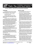
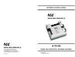
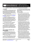
Daytona Sensors LLC User Instructions for Engine Controls and Instrumentation Systems WEGO Log Software CAUTION: CAREFULLY READ INSTRUCTIONS BEFORE PROCEEDING. THE USER IS ASSUMED TO BE FAMILIAR WITH MICROSOFT WINDOWS AND PC OPERATION. OVERVIEW WEGO Log software runs under Microsoft Windows 98/ME/XP. This software allows WEGO II users to download and display data logged by the unit and to setup certain data logging functions. After WEGO Log is launched, the main screen appears blank. Data logged by the WEGO II unit must be downloaded before it can be displayed, by using the Download Data From WEGO command on the Communications menu. Once data has been downloaded, it is automatically displayed on a chart recorder type screen. You can save this data by using the Save File command from the File menu. You can also display a previously saved data file by first using the Open File command on the File menu. A sample data file (Sample.log) for an actual road test is included in the program folder. PC REQUIREMENTS The WEGO II has a female 9 pin D-sub connector that interfaces to an RS-232 serial port on the laptop PC. In most cases, you will need to use a 9 pin male-to-female extension cable such as our P/N RS232-CBL-10 to reach the PC. Similar cables are available from Belkin (www.belkin.com) as P/N F2N209-06-T or Office Depot as P/N 825851. You can also find the same type of cable at most office and computer supply stores. Data transfer occurs at 56 kBaud. The high baud rate limits the maximum cable length and the use of an extension cable over 12 feet in length is not recommended. Due to the cable length limitation and the need for portable access, a laptop PC is recommended. The PC must have a free serial port (COM1-255) with a standard 9 pin male D-sub connector. If your laptop does not include a serial port, you can use a USB adapter. However, not all USB adapters will work correctly with the WEGO II. Most of the inexpensive USB adapters are intended for interfacing Palm Pilot type devices and do not support the high baud rate required by our unit. We sell and recommend a low cost USB adapter (P/N USBG-232) that has been tested with a wide range of system configurations. The USBG-232 adapter comes with correct and updated driver files on CDROM. After installation the USBG-232 adapter will usually appear as COM5. We recommend a laptop with Pentium processor and super VGA display (SVGA with 1024 x 768 pixel resolution) running Windows 98/ME/XP. Data chart display is graphics intensive and a high speed Pentium processor is recommended. Processors slower than 300 MHz will exhibit sluggish program loading and response. The PC must have a CDROM drive for program loading. WEGO Log includes print commands to print downloaded data. The program has been tested with Hewlett-Packard laser and inkjet printers and Epson inkjet printers. We recommend using a color inkjet printer. SOFTWARE INSTALLATION The software is supplied on CDROM media or in the form of a compressed file downloaded from our website. The installation process uses InstallShield. This industry standard installer is based the new Microsoft Windows Installer service that greatly reduces potential problems such as version conflicts and allows for application self-repair. Since Windows 98 systems did not originally include the Windows Installer service, the required installer software is included in the distribution media. Before proceeding with installation, shutdown any other applications that may be running. Use the Windows Explorer or the Run command from the Windows Start Menu to launch setup.exe in the WEGO_Log folder on the CDROM or the setup.exe file downloaded from our website. InstallShield will install the software in an appropriate folder under Program Files. Once InstallShield has completed the installation, WEGO Log will appear on the Windows Start Menu. You can then launch it just as you would any other Windows program. WEGO Log requires the Monospace 821 BT fixed pitch printer font in order to properly align columns when printing. The Monospace 821 BT font is Daytona Sensors LLC, 933 Beville Road, Suite 101-I, S. Daytona, FL 32119 (386) 322-7390 www.daytona-sensors.com Page 1 WEGO Log 4/2006 included in the distribution media and automatically copied to your Windows Fonts folder during installation. A backup copy is also placed in the program folder. If you accidentally delete this font, use the Install New Font command from the Fonts folder File menu. The filename associated with Monospace 821 BT is monos.ttf. WEGO II CONNECTION Use an extension cable to connect the WEGO II to a serial port on your laptop PC or USB adapter. Turn on power to the WEGO II unit. We recommend that you do not run the engine while you are downloading data. COM1 is used as the default port. If you connected the WEGO II to a different COM port, use the Port Setup command on the Communications menu. WEGO II SETUP Prior to using the WEGO II, you must set up the data logging parameters. Use the Edit WEGO Parameters command from the Edit menu. A dialog box will appear as shown in Figure 1. You can set the data logging interval and RPM pulses per revolution. The WEGO II data buffer stores the last 8000 data points. If you set the data logging interval to 0.50 seconds, the unit will log over one hour of data. Data logging intervals of 0.2-1.0 seconds are suitable for onroad tests; a shorter interval of 0.10 seconds is recommended for dyno tuning. You can clear the data within the WEGO II by using the Clear WEGO Data Buffer command from the Communications menu. If you change the data logging interval, you should also clear the WEGO II data buffer. If you are logging engine RPM, you must set the correct value for RPM pulses per revolution (PPR). Some general guidelines follow, based on what type of signal you have connected to the WEGO II brown wire: Tach signal. In most cases PPR= N/2 where N is the number of cylinders. For example a V-twin motorcycle engine would require PPR=1and a V8 automotive engine would require PPR=4 Harley-Davidson dual fire ignition with connection to Coil- terminal. Use PPR=1 Harley-Davidson single fire ignition with connection to either Coil- terminal. Use PPR=0.5 Distributor type ignition with connection to Coilterminal. Same as for a tach signal. Use PPR= N/2 where N is the number of cylinders. Wasted spark coil pack (distributorless system) with connection to Coil- terminal. Use PPR=1. Coil on plug (no wasted spark) with connection to Coil- terminal. Use PPR=0.5 Capacitive Discharge (CD) ignition using tach adapter. For one cylinder engines, use PPR=1 After you have entered the correct parameters, you must upload them to the WEGO II unit. Please note that clicking on Restore Defaults only displays default values and does not affect the WEGO II unless you then upload the restored values. Figure 1 – Data Logging Setup Daytona Sensors LLC, 933 Beville Road, Suite 101-I, S. Daytona, FL 32119 (386) 322-7390 www.daytona-sensors.com Page 2 WEGO Log 4/2006 DATA LOGGING CHART DISPLAY Data logged by the WEGO II unit is displayed on a chart recorder type screen. Data logged by the WEGO II unit must be downloaded before it can be displayed, by using the Download Data From WEGO command on the Communications menu. Once data has been downloaded, it is automatically displayed. The last data logged will appear at the right end of the chart. You can save this data by using the Save File command from the File menu. You can display a previously saved data file by first using the Open File command on the File menu. Note that WEGO data files use a .log extension. You should create a separate folder to store these files. You have a range of capabilities for analyzing downloaded data displayed in the chart recorder format. You can select two parameters for display. Trace 1 is displayed in red with its Y axis legends on the left side of the chart. Trace 2 is displayed in green with its Y axis legends on the right side of the chart. The X axis is always elapsed time. You can select from one of four time scales. You can use the scroll bar to move the chart display window in terms of elapsed time. If you hold the left mouse button down within the chart area, a cursor line appears. The exact values of the parameters displayed on trace 1 and trace 2 and the elapsed time appear in windows above the chart. Figure 2 – Data Logging Chart Display Daytona Sensors LLC, 933 Beville Road, Suite 101-I, S. Daytona, FL 32119 (386) 322-7390 www.daytona-sensors.com Page 3 WEGO Log 4/2006 If you want to analyze the elapsed time between two events, you can move the cursor to the first event and then click on the Reset Time Display button. You can print the displayed chart to any Windows printer by clicking on the Print button (a color inkjet printer is recommended for best results). Data parameters include: RPM – engine crankshaft RPM Figures 4 and 5 show settings for standard GM/Delphi 1 bar and 2 bar manifold pressure (MAP) sensors. Most GM vehicles and all Harley-Davidson® motorcycles with Twin-Cam 88® engines use GM 1 bar type MAP sensors. GM 2 bar MAP sensors are often used with aftermarket engine controls for turbo/supercharger applications. Figure 3 – Input Scaling for Typical TPS AFR – air/fuel ratio (10:1 to 20:1 for gasoline) ANALOG INPUT – analog signal input that can be scaled and displayed in user selected units (as explained further on). You can use the Maximum RPM command from the Edit menu to change the maximum RPM value displayed on the chart. Additional data is displayed at the lower right side of the screen. This data includes: Diagnostic Code – normally blank unless a diagnostic code is set. Diagnostic codes include battery low, battery high, sensor open, and sensor short. Log Interval – the actual data logging interval in seconds Figure 4 – Input Scaling for GM 1 Bar MAP The data logging interval is displayed at the lower right side of the screen. The WEGO II data buffer stores the last 8000 samples. You can clear the data within the WEGO II by using the Clear WEGO Data Buffer command from the Communications menu. If you change the data logging interval, you should also clear the WEGO II data buffer. ANALOG INPUT SCALING When a chart display is active, you can use the Analog Input Scaling command on the Edit menu to setup the scaling and units display for the analog input. In general, you will enter the minimum and maximum input voltages and corresponding scaled values displayed on the chart along with the desired chart legend. The minimum and maximum voltages must be in the range of 0.0-5.0 volts. The scaled values must be in the range of 0-10,000. Once entered, analog input scaling values are saved with the data. Clicking on Restore Defaults causes the program to revert to direct 0.0-5.0 volt display on the chart. Figure 3 shows settings for a typical throttle position sensor (TPS), with 0.4 volts corresponding to 0% and 4.5 volts corresponding to 100%. Daytona Sensors LLC, 933 Beville Road, Suite 101-I, S. Daytona, FL 32119 (386) 322-7390 www.daytona-sensors.com Page 4 WEGO Log 4/2006 Figure 5 – Input Scaling for GM 2 Bar MAP IMPORTING DATA INTO EXCEL Data files saved from WEGO Log are in comma delimited ASCII format. You can easily import a data file into other programs such as Microsoft Excel for further analysis. You can also view data files with a text editor such as Windows WordPad. To import a data file into Excel: 1. Start Excel. In the File Open dialog box, select Files of type: All Files (*.*). Then browse for the data file. 2. The Text Import Wizard appears. For step 1, select delimited file type. For step 2, select comma delimiter. For step 3, select general column data format. Then click on Finish. 3. You can then format the data and save the spreadsheet as an Excel file. For other types of sensors, we suggest that you check the sensor output waveform with a scope meter. Verify that the sensor output is an analog voltage within the 0.0-5.0 volt range. Some Ford MAP sensors and GM mass airflow (MAF) sensors use a frequency output that is not compatible with the WEGO II analog input. Once you verify that the sensor has an analog output, you still have to determine the output scaling. You may find this information in the service manual or you may have to do some reverse engineering with a scan tool. AFR data is saved as gasoline AFR values regardless of fuel type setting. To convert to methanol AFR values, use the formula: AFR Methanol = .4354 x Gasoline AFR TROUBLESHOOTING FLOWCHART Follow the troubleshooting flowchart shown on the next page. Experience has shown that most communication problems are user error or PC compatibility issues. FUEL TYPE When a chart display is active, you can use the Fuel Type command on the Edit menu to setup the scaling of AFR values for either gasoline or methanol fuel. All WEGO II units will log data correctly for either gasoline or methanol fuel, however, only WEGO2M units will correctly display methanol AFR values on the LCD display. The program initially defaults to gasoline fuel, but remembers the type of fuel last selected. Daytona Sensors LLC, 933 Beville Road, Suite 101-I, S. Daytona, FL 32119 (386) 322-7390 www.daytona-sensors.com Page 5 WEGO Log 4/2006 Troubleshooting Flowchart STARTING POINT IS RS-232 TIMEOUT ERROR MESSAGE DISPLAYED WHEN ATTEMPTING PC COMMUNICATIONS? YES NO FOR MISC PROBLEMS, CALL TECH SUPPORT. CYCLE POWER. VERIFY WEGO II STATUS LED ILLUMINATED. IS PROBLEM FIXED? YES NO DONE USE WINDOWS DEVICE MANAGER TO VERIFY THAT CORRECT COM PORT IS SELECTED. IS PROBLEM FIXED? YES NO FIRST TIME USE OF USB ADAPTER THAT WAS SUPPLIED BY A THIRD PARTY (NOT SOLD AS PART OF OUR SYSTEM)? DONE YES NO USB ADAPTER MAY BE INCOMPATIBLE. REPLACE USB ADAPTER (REFER TO INSTRUCTIONS). IS PROBLEM FIXED? YES DONE NO OTHER SOFTWARE ON PC THAT USES COM PORT SUCH AS PALM PILOT OR DIGITAL CAMERA? YES DISABLE OTHER SOFTWARE. PALM PILOT - MAKE SURE HOT SYNC ICON DOES NOT APPEAR IN SYSTEM TRAY. IS PROBLEM FIXED? NO USE ANOTHER PC OR UNINSTALL OFFENDING SOFTWARE. IN SOME CASES YOU MAY HAVE TO RELOAD WINDOWS. CALL TECH SUPPORT FOR FURTHER INFORMATION. NO CALL TECH SUPPORT YES DONE Daytona Sensors LLC, 933 Beville Road, Suite 101-I, S. Daytona, FL 32119 (386) 322-7390 www.daytona-sensors.com Page 6 WEGO Log 4/2006