1
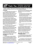
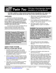
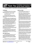
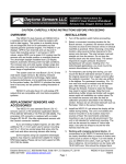
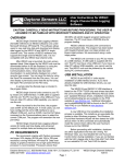
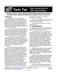
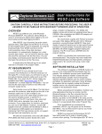
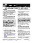
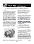
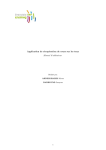
Twin Tec Installation Instructions for VRFI D Version Fuel Injection Controller CAUTION: CAREFULLY READ INSTRUCTIONS BEFORE PROCEEDING. NOT LEGAL FOR USE OR SALE ON POLLUTION CONTROLLED VEHICLES. OVERVIEW The Twin Tec VRFI D version fuel injection controller replaces the original equipment (OE) 36 pin Delphi® controller on Harley-Davidson V-Rod motorcycles with fuel injected VRSC engines. The term VRFI is used throughout this document as a generic term and refers to the new VRFI D version controller unless otherwise noted. The VRFI is intended for high performance race engines. The VRFI solves tuning problems with highly modified engines. Competitive “band-aid” products that interface to the Delphi® controller still rely on speeddensity fuel control. Long duration/high overlap camshafts wreak havoc with manifold pressure especially at idle and cruise RPM. Speed-density based fuel control simply can’t cope. High-end automotive racing systems use alphaN (throttle position and RPM based) fuel control. Alpha-N eliminates any dependence on manifold pressure and is unaffected by long duration/high overlap camshafts. The VRFI brings this proven technology to the H-D® marketplace. The VRFI D version kit includes the new WEGO IIID dual channel wide-band exhaust gas oxygen sensor interface that allows simultaneous front and rear cylinder auto-tuning during actual riding conditions. The WEGO IIID interface uses low cost Bosch LSU 4.2 wide-band sensors. The VRFI has the same ignition control as our proven TCFI (Twin Cam Fuel Injection) with fully programmable advance curves. Idle air control including idle RPM and cold start characteristics are also fully programmable. This facilitates the use of aftermarket throttle bodies with increased airflow. The VRFI includes extensive diagnostic capabilities and built-in data logging. The unit is compatible with standard H-D scan tools. Engine data is logged for the last 15 minutes of operation. A PC link cable and Windows compatible software allow the use of a laptop PC for programming and data analysis. The PC link cable plugs into the existing diagnostic connector on the motorcycle wiring harness. ADDITIONAL REQUIRED PARTS Unless you have purchased a pre-programmed unit sold as part of a performance package, the VRFI will require initial setup and tuning of the fuel tables. The PC link cable is required for setup. The wide-band oxygen sensor interface (P/N WEGO3D) is required for auto-tuning fuel tables. PRE-INSTALLATION CHECKS Make sure that the OE Delphi® system is functioning correctly (other than tuning issues) before attempting VRFI installation. If the OE Delphi® system is setting diagnostic codes, find and correct any underlying problems first. Correct adjustment of the throttle position sensor (TPS) and idle stop screw, along with free operation of the throttle linkage, are all critical for proper operation of the VRFI system. The voltage at pin C (typically green/violet wire) of the TPS must be in the range of 0.30-0.80 volts at idle. You can use VRFI Log software to check the idle TPS voltage. Refer to the VRFI Tuning Manual for details. With alpha-N fuel control, the TPS is critical. The TPS has a resistance element similar to the volume control on a radio. In time, it will wear out and become noisy. We recommend replacing the TPS after 10,000 miles. INSTALLATION 1. If motorcycle is equipped with security system (TSSM module), make sure system is disarmed. Turn off the ignition switch. Remove the right side cover and maxi-fuse before proceeding. 2. Remove the left cover to access the Delphi® module. Remove the Delphi® module from the left side. 3. Install the VRFI module a shown in Figure 1. The module is a very tight fit. You will have to push the adjacent wire harness aside. Use the 6-1.00 x 30mm socket head cap screws supplied with the VRFI kit. Insert the screws into the VRFI housing and use short strips of masking tape to hold them in place while sliding the VRFI into position. To tighten the screws, you will require a stubby 5mm Daytona Twin Tec LLC, 933 Beville Road, Suite 101-H, S. Daytona, FL 32119 (386) 304-0700 www.daytona-twintec.com Page 1 VRFI D Vesrion Installation 10/2007 hex key (such as MSC 83827642). You may have to trim the stubby hex key to fit early applications. Figure 2 – Front Sensor Installation Figure 1 - VRFI Installation Figure 3 – Rear Sensor Installation 4. 2006 and later models only (skip ahead to step 5 for 2002-2005 models). The VRFI parts bag includes a green PC link jumper wire with a male Deutsch terminal on one end and a small female Delphi Micro-Pack terminal on the other end. Install this wire between pin 1 of the Delphi connector that mates with the TCFI module and pin 1 of the OE diagnostic connector (four terminal Deutsch). Refer to the factory service manual for connector location and disassembly techniques. 5. Install the WEGO IIID system. Follow the instructions supplied with the WEGO IIID, except as noted herein. You can mount the WEGO on top of the battery with strips of Velcro material. To provide clearance, you may have to trim some material from the airbox inlet. Connect the black WEGO ground wires to the wire harness ground point on the upper left side of the engine using the 3/8” ID ring tongue terminal supplied with the VRFI kit. You will have to remove the airbox for access. 6. With the VRSC engine, the space available for exhaust gas oxygen sensor mounting is limited, especially for the rear sensor. Refer to Figures 2 and 3 for suggested sensor mounting locations. Mock up the installation carefully before drilling and welding. 7. Reinstall the maxi-fuse and right side cover. Do not attempt to start the engine until you have completed the initial setup. INITIAL SETUP The VRFI requires initial setup, using PC Link VRFID software, before running the engine for the first time. Setup establishes module parameters such as engine displacement, injector size, and appropriate ignition and fuel control tables. WARNING: You must carefully read the VRFI D Version Tuning Manual and the instructions for the PC Link VRFID and VRFI Log software. If you do not follow all the instructions, you will probably damage your engine. Daytona Twin Tec LLC, 933 Beville Road, Suite 101-H, S. Daytona, FL 32119 (386) 304-0700 www.daytona-twintec.com Page 2 VRFI D Vesrion Installation 10/2007 If you are using an aftermarket throttle body, you must also adjust the throttle stop and throttle position sensor setting at idle. Refer to the VRFI Tuning Manual for details. firmware, you must also cycle the run/stop switch, as explained above, in order to properly initialize the idle air control motor. GENERAL RECOMMENDATIONS WARNING: You must use the new version 4.0 or higher PC Link VRFID software for setup and tuning. You cannot use the original PC Link VRFI software. To access all data, you must also use the new version 3.0 or higher VRFI Log software. ENGINE STARTING PROCEDURE With alpha-N fuel control, the proper engine starting procedure must be followed. When the run/stop switch is turned on, the VRFI reads the TPS voltage to establish zero percent throttle position. If the throttle is not fully closed at this point, all subsequent fuel control will be incorrect. The throttle body is affected by thermal expansion. If the engine has cooled down or the motorcycle has sat overnight, we suggest that you momentarily open and then release the throttle before turning the run/stop switch on. Make absolutely sure that the throttle is fully closed before turning the run/stop switch on. The throttle friction adjustment screw may prevent the throttle from fully closing. We suggest that you always leave this screw fully counterclockwise. When the run/stop switch is turned on, the idle air control motor will move to the starting position and the fuel pump will be energized for several seconds, making an audible buzz. Do not press the starter button until the fuel pump stops buzzing. When you turn the run/stop switch off, the idle air control motor requires several seconds to return to its home position. After turning the run/stop switch off, you must wait for 5 seconds before turning the switch on again. If the engine stalls, we suggest that you cycle the run/stop switch off for 5 seconds and then on again before attempting a restart. Let the engine idle for about 20-30 seconds before operating the motorcycle. This allows the closed loop idle air control system to stabilize idle RPM. If you make any changes or adjustments to the throttle body, disconnect the battery or maxi-fuse, swap out the VRFI unit, or upload new data or The VRFI is designed to be used with the OE VRSC coils. Do not attempt to use any aftermarket coils or non-resistor spark plugs. ENGINE DIAGNOSTICS The VRFI D version has extensive diagnostics and is compatible with H-D scan tools that connect to the OE diagnostic link. When the ignition switch is first turned on, the check engine LED illuminates. The LED goes out when the engine is started. If a diagnostic fault is detected while the engine is running, the LED will illuminate. Diagnostic codes can be read with a scan tool or by means of the VRFI Log software. Most of the diagnostic codes are the same as those used by H-D and the H-D Electrical Diagnostic Manual for your model should be employed as a primary troubleshooting reference. Certain diagnostic codes that are unique to the VRFI or require special consideration are listed below: P0373 CKP Signal Lost. This code will appear if the engine stalls. Customers are often confused about the meaning of the term “trips” associated with codes, especially P0373. This is an industry standard terminology. If code P0373 shows 40 trips, it means that the code was set 40 engine start cycles ago, not that the code has been set 40 times and that the crankshaft position sensor is defective. P0122 TPS Low or P0123 TPS High. If these codes appear on a new installation, the TPS idle adjustment is probably incorrect. Refer to the VRFI Tuning Manual for details. P0505 Loss of Idle Speed Control. If this code appears on a new installation, the throttle body idle stop setting is probably incorrect. Refer to the VRFI Tuning Manual for details. P0132 Rear Oxygen Sensor High, P0134 Rear Oxygen Sensor Low/Open, P0152 Front Oxygen Sensor High, or P0154 Front Oxygen Sensor Low/Open. These codes indicate a problem with the WEGO IIID unit. P0134 and/or P0154 will be set if the WEGO signal connection (white and blue wires) or WEGO power is lost. These codes may also be set if a Bosch sensor Daytona Twin Tec LLC, 933 Beville Road, Suite 101-H, S. Daytona, FL 32119 (386) 304-0700 www.daytona-twintec.com Page 3 VRFI D Vesrion Installation 10/2007 fails or becomes contaminated by leaded gasoline. AFTERMARKET TACHOMETER Like the Delphi® module, the VRFI sends RPM data to the instrument module over the J1850 data bus. The VRFI also has a conventional 12 volt square wave tach signal (one pulse per revolution) available on pin 3. This tach signal is compatible with most aftermarket tachometers and other RPM activated accessories intended for H-D® racing applications. REINSTALLING THE DELPHI® CONTROLLER starting the engine. This initializes the idle air control motor. Removal of the white and blue WEGO signal wires is not required. TROUBLESHOOTING FLOWCHART Follow the troubleshooting flowchart shown on the next page. Please note that the troubleshooting flowchart does not relate to incorrect setup or tuning issues with new installations. Experience has shown that most units returned for warranty are OK and another problem, such as user error including improper setup or tuning, an intermittent wire harness connection, or defective coil, fuel injector, or sensor is later identified. If you reinstall the Delphi® controller, turn the ignition key on and cycle the run/stop switch before Daytona Twin Tec LLC, 933 Beville Road, Suite 101-H, S. Daytona, FL 32119 (386) 304-0700 www.daytona-twintec.com Page 4 VRFI D Vesrion Installation 10/2007 Troubleshooting Flowchart STARTING POINT REPLACE VRFI WITH OE MODULE OR ANOTHER KNOWN GOOD MODULE. IS PROBLEM FIXED? YES NO REPAIR UNDERLYING PROBLEM BEFORE INSTALLING VRFI. REFER TO MOTORCYCLE SERVICE MANUAL REINSTALL VRFI TURN IGNITION ON. SET ENGINE SWITCH TO RUN. IS CHECK ENGINE LED ILLUMINATED? NO YES DOES ENGINE START? REPLACE VRFI NO YES DOES CHECK ENGINE LED REMAIN ILLUMINATED OR ILLUMINATE AFTER A SHORT TIME? REPLACE VRFI NO YES REFER TO ENGINE DIAGNOSTICS SECTION. FIX APPLICABLE PROBLEM. DOES ENGINE STOP OR DROP CYLINDER AFTER SEVERAL MINUTES OF RUNNING? NO YES REPLACE COILS. IS PROBLEM FIXED? YES DOES ENGINE MISFIRE UNDER LOAD? NO NO REPLACE VRFI DONE YES REPLACE SPARK PLUGS AND COILS. IS PROBLEM FIXED? YES DONE NO REPLACE VRFI DOES ENGINE MISFIRE AT PART THROTTLE OR WHILE COLD? NO FOR MISC PROBLEMS, CALL TECH SUPPPORT. YES CHECK FOR INCORRECT COLD START SETTINGS OR INTAKE LEAK. IS PROBLEM FIXED? YES DONE Daytona Twin Tec LLC, 933 Beville Road, Suite 101-H, S. Daytona, FL 32119 (386) 304-0700 www.daytona-twintec.com Page 5 NO REPLACE VRFI VRFI D Vesrion Installation 10/2007