1
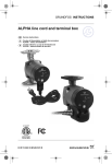
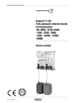
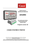
GRUNDFOS DATA BOOKLET ® Oxiperm Pro Safe, reliable, on-site generation and dosing of chlorine dioxide for water disinfection Oxiperm® Pro Table of contents 1. 2. 3. 4. 5. 6. 7. 8. 9. 2 Product introduction 3 Introduction Applications Features and benefits 3 3 4 Components 6 Identification 8 Type key 8 Construction 9 Oxiperm Pro OCD-162-5 and OCD-162-10 Oxiperm Pro OCD-162-30 and OCD-162-60 9 10 Installation 11 Preparation 11 Technical data 13 Electrical and electronic data Dimensions 14 15 Product selection 18 How to size Oxiperm Pro® 18 Accessories 19 Dosing pumps ClO2 pump control cables Multifunction valve Injection valve Connectors Instrumentation Conex DIA-G gas warning unit Photometer Suction lines Connections Annual maintenance kits 19 19 19 19 19 20 20 20 20 21 21 Further product documentation 22 WebCAPS WinCAPS 22 23 Oxiperm® Pro 1 The chlorine dioxide solution produced is stored in either an integrated or external batch tank, while the required addition of the disinfectant to the water line is accomplished via either an integrated or external dosing pump. Chlorine dioxide is highly effective against a wide variety of pathogens. Additionally, it demonstrates a prolonged residence time in piping systems, eliminating the requirement for re-dosing downstream. A significant advantage of chlorine dioxide over other disinfectants is its effectiveness against biofilms. Biofilm is a slimy layer on the inside of water pipes or on process equipment, where pathogens build up and reproduce. Chlorine dioxide destroys the existing biofilm, thus removing a primary area for the growth of pathogens, while preventing recurrent biofilm buildup. Applications Oxiperm Pro OCD-162-5 and -10 systems are designed for small or medium-sized systems with water flows up to 110 gpm (25 m³/h). Oxiperm Pro OCD-162-30 and -60 systems are suited for medium or large-sized systems; and disinfection tasks in waterworks or applications in the food and beverage industry. All four units are ideal for use in cooling tower or chilled loop disinfection for systems of various sizes. Biofilms are an ideal breeding ground for legionella in drinking water systems. Legionella also establish themselves in amoebae, which offer them protection against conventional disinfection methods. Typically, disinfection is the first step of pathogen reduction within continuing operations of a drinking water installation. An ideal means of ensuring safe drinking water is to use chlorine dioxide as a disinfectant. In addition to its use as a primary disinfectant for potable and process water, chlorine dioxide is often used in the food and beverage industries for CIP (clean in place) and bottle washing. This is due to the fact that the use of chlorine dioxide does not alter the smell or taste of the treated water. This results in the elimination of concerns having to do with alteration of the food product’s characteristics. Effectiveness diagram 100 pH > 7.5 80 60 Residual germs HClO 40 20 Residual germs with ClO2 0 0.01 0.02 0.03 0.04 0.05 Concentration of disinfection [mg/l] Fig. 1 0.06 TM04 1462 0410 Oxiperm Pro systems produce chlorine dioxide using dilute solutions of sodium chlorite (NaClO 2 7.5 %) and hydrochloric acid (HCl 9 %). The systems are available in four size ranges, producing a maximum of 5, 10, 30 and 55 g/h of chlorine dioxide, respectively. The largest unit is capable of generating chlorine dioxide in an amount sufficient to treat up to 660 gpm (150 m³/h) of potable water at the maximum admissible concentration of 0.8 mg/l ClO2. Chlorine dioxide is produced on demand from diluted solutions using sodium chlorite/hydrochloric acid. The bacteria can enter the lungs when a person inhales aerosols containing legionella while showering or in cooling tower drift. They can cause a lifethreatening form of pneumonia known as legionellosis (Legionaires disease). Residual germs [%] Introduction Product introduction 1. Product introduction Effectiveness diagram: HCIO = hypochlorous acid, ClO2 = chlorine dioxide Ideal applications for Oxiperm Pro include combating pathogens such as legionella pneumophilia (cause of Legionaires disease) in building, cooling tower, industrial and municipal water systems. No chance for pathogens Legionella are rod-shaped bacteria that enter drinking water systems and start to reproduce. Legionella reproduce especially quickly in temperatures between 85 °F (29 °C) and 105 °F (41 °C). 3 Oxiperm® Pro 1 Product introduction Features and benefits Compact system Oxiperm Pro can also be installed in tight or restrictive spaces, as operation and maintenance are performed exclusively from the front. Low operating costs This intelligent method for producing chlorine dioxide functions with minimal need for chemicals and thus saves up to 67 % of hydrochloric acid over other systems on the market with comparable capacity. In comparison with thermal disinfection, up to 90 % of the operating costs can be saved. Integrated measurement value logging device (optional) The chlorine dioxide control unit can be easily retrofitted, as the connection for a measuring device for chlorine dioxide as well as pH or Redox (measuring cell) is already in place in the system control. Little installation work Optional accessories simplify assembly and start-up. In fact, the system can be connected and taken into operation without even interrupting the building’s water supply. This represents a decisive cost factor when it comes to decontaminating hospitals or nursing homes. Robust design Oxiperm Pro’s robust design ensures high operational reliability and lower maintenance costs. Furthermore, the newly designed control system makes for straightforward and user-friendly operation and opens up a number of application areas for discrete disinfection of drinking water installations. Wide field of applications Besides continuous operation, the optional external batch tank allows the use of Oxiperm Pro for shock disinfection, in cleaning applications, such as CIP, or for multi-point injection. 4 TM04 1461 0310 Stable product solution With a chlorine dioxide concentration of 2 g/l (2000 ppm), the product solution can be stored for several days. The low concentration makes the solution safe to handle. Fig. 2 Oxiperm Pro systems Oxiperm® Pro 1 Product introduction This page intentionally left blank. 5 Oxiperm® Pro 2 Components 2. Components 3 4 3 2 4 2a 1 7 8 Fig. 3 6 9 Components of an installation for chlorine dioxide preparation 6 TM05 3873 1712 5 Oxiperm® Pro 2 No. Component Components Checklist of installation components Page Basic unit 1 Oxiperm Pro chlorine dioxide preparation system 9 Dilution water for Oxiperm Pro 2 PE hose 1/4" x 3/8" for dilution water connection 13 2a Alternative 1/2" NPT connection 19 Dosing of chlorine dioxide 3 4 Injection valve for the direct dosing of chlorine dioxide into the water pipe Inlet: 1/4", 3/8", 1/2" tube; 1/2" NPT Discharge: 1/2" NPT 19 ClO2 line 162 5 and 10: 1/8" ID x 1/4" OD tubing connection 162 30 and 60: 1/4" ID x 3/8" OD tubing connection 13 1/2" NPT connections available for all sizes 19 Chlorine dioxide measurement 5 ClO2 measuring cell, 3/8" x 1/2" tubing inlet/discharge 6 External batch tanks 7 Hand photometer with reagents for calibrating ClO2 controller 20 20 Safety equipment 8 Gas warning unit 9 Personal protective equipment (gloves, apron, goggles), warning signs 20 Maintenance Annual maintenance kit 7 Oxiperm® Pro 3 Identification 3. Identification Type key Example: Type key Oxiperm Pro OCD-162-30-P/H3 Oxiperm Pro OCD-162 -30 Max. Capacity 5 5 g/h 10 10 g/h 30 30 g/h 60 55 g/h Operation mode D integrated mechanical dosing pump, DMX P integrated Digital Dosing pump DDI S integrated SMART Digital Dosing pump DDA N without integrated ClO2 dosing pump Supply voltage G 230-240 V / 50-60 Hz H 110-120 V / 50-60 Hz Suction line for 7.9 gal (30 liter) chemical tank, with 4.3 ft (1.3 m) of tubing 8 1 for 15.6 gal (60 liter) chemical tank, with 9.8 ft (3.0 m) of tubing 2 for 52.8 gal / 264.2 gal (200 liter / 1000 liter) chemical tank, with 19.7 ft (6.0 m) of tubing 3 for 55 gal drum, with 9.8 ft (3.0 m) of tubing -P /H 3 Oxiperm® Pro 4 Construction 4. Construction Oxiperm Pro OCD-162-5 and OCD-162-10 TM04 8507 0912 Fig. 4 Oxiperm Pro OCD-162-5 (left) and Oxiperm Pro OCD-162-10 (right) with open housing Legend 1 Measuring and control unit 2 Reaction tank 3 Reservoir tank 4 Adsorption filter 5 Dosing pump, 7.5% Sodium Chlorite 6 Dosing pump, 9% Hydrochloric Acid 7 Chlorine Dioxide dosing pump 8 Solenoid valve for dilution water 9 Suction lance 10 Chemical container (not in standard delivery) 11 Collecting tray (not in standard delivery) 9 Oxiperm® Pro 4 Construction Oxiperm Pro OCD-162-30 and OCD-162-60 1 2 2 4 4 3 5 6 8 8 5 6 7 3 9 9 TM04 1483 0410 9 7 Fig. 5 Oxiperm Pro OCD-162-30 (left) and Oxiperm Pro OCD-162-60 (right) with open housing Legend 10 1 Measuring and control unit 2 Reaction tank 3 Reservoir tank 4 Adsorption filter 5 Dosing pump, 7.5% Sodium Chlorite 6 Dosing pump, 9% Hydrochloric Acid 7 Chlorine Dioxide dosing pump 8 Solenoid valve for dilution water 9 Suction lance Oxiperm® Pro 5 Installation 5. Installation Preparation One dosing point 8 2 4 3 6 12 9 13 7 4 10 11 18 1 TM05 6867 0213 5 Fig. 6 Oxiperm Pro basic module with optional measuring cell for chlorine dioxide in cold water Legend 1 Oxiperm Pro OCD-162-5, -10, -30, or 60 2 Main water pipe 3 Dilution water extraction point 4 Dilution water pipe 5 Y-Strainer 6 Flow measurement 7 Signal line flow measurement 8 Injection unit 9 Dosing line 10 Chlorine dioxide measuring cell 11 Signal line chlorine dioxide measurement 12 Sample water extraction point (minimum distance of approx. 17 ft (5 m) from ClO2 injection point) 13 Sample water line to measuring cell 18 Sample water drain line 11 Oxiperm® Pro 5 Installation Several dosing points with batch tank 8 2 3 6 9 9 7 8 4 4 2 7 6 13 12 11 21 5 1 10 9 18 17 Fig. 7 Oxiperm Pro basic module with additional dosing pumps on a batch tank and optional chlorine dioxide measurement Legend 12 1 Oxiperm Pro 2 Main water pipe 3 Dilution water extraction point 4 Dilution water pipe 5 Y-Strainer 6 Flow measurement 7 Signal line flow measurement 8 Injection unit 9 Dosing line 10 Chlorine dioxide measuring cell 11 Signal line chlorine dioxide measurement 12 Measuring water extraction point (min. distance to injection unit approx. 17 ft (5 m)) 13 Sample water pipe 17 Additional ClO2 dosing pumps 18 Sample water drain 20 Batch tank 21 Signal line batch tank TM05 6868 0213 20 Oxiperm® Pro 6 Technical data 6. Technical data OCD model Chlorine dioxide generator ClO2 production [lbs/day (grams/hr)] ClO2 concentration [ppm] [gal/hr (l/hr)] Precursor concentration by weight 162-10 0.26 (5) 0.53 (10) 162-30 162-60 1.59 (30) 2.9 (55) 2000 Max continuous ClO2 dosing feed rate* [gal/hr (l/hr)] (i.e. max. ClO2 pump output at 20mA) Consumption data 162-5 NaClO2 HCl H 20 HCl NaClO2 0.66 (2.5) 1.32 (5) 3.96 (15) 7.26 (27.5) 0.044 (0.17) 0.036 (0.14) 0.607 (2.3) 0.097 (0.37) 0.079 (0.3) 1.268 (4.8) 0.232 (0.88) 0.227 (0.86) 3.909 (14.8) 0.41 (1.57) 0.39 (1.49) 7.87 (29.79) 9% 7.5 % Precursor safety equipment Capacity monitored via level control Temperature range [°F (°C)] Dilution water pressure [psi (bar)] Ambient Dilution H20 HCl & NaClO2 40 to 95 °F (5 to 35 °C) 50 to 85 °F (10 to 30 °C) 50 to 95 °F (10 to 35 °C) 44 to 87 psi (3 to 6 bar) Admissible relative air humidity max. 80 %, not condensing Total volume - reaction tank [gal (liters)] 0.26 (1.0) 0.48 (1.8) 1.6 (6.1) 3.5 (13.4) Total volume - reservoir tank (up to max level alarm) [gal (liters)] 0.26 (1.0) 0.48 (1.8) 1.85 (7.0) 3.67 (13.9) Filling volume - reaction tank [gal (liters)] 0.23 (0.87) 0.44 (1.67) 1.46 (5.52) 3.16 (11.96) Filling volume - reservoir tank (up to max level alarm) [gal (liters)] 0.23 (0.87) 0.44 (1.67) 1.72 (6.5) 3.43 (13.0) Materials of construction Connections Full text menu control System rack Fastening sleeves Solenoid valve Reaction/reservoir tank Internal hoses Gaskets ClO2 dosing line Dilution water NPT adaptor Commissioning Operation parameters Flush / rinsing Maintenance Electrical safety Approvals NSF 61 PWT Polypropylene Stainless steel PVC PVC PTFE FPM 1/8" ID x 1/4" OD tube 1/4" ID x 3/8" OD tube 1/4" ID x 3/8" OD tube 1/2" NPT connector - see 8. Accessories on page 19. Yes Yes Yes Yes Conforms to ANSI/UL 61010-1 Chlorine Dioxide Generator model numbers OCD-162-5, OCD-162-10, OCD-162-30 and OCD-162-60 are certified to NSF 61-2011 requirements found in clause 3.3.2. (a) These chemical generators are certified for use exclusively at public water treatment facilities. Products installed at public water treatment facilities are considered to be used in high flow applications. (b) Certification of this product has been performed to the health effects requirements of NSF/ANSI 61, which assesses the acceptability of potential extractants from the chemical generator. No evaluation has been performed on the strength or efficacy of the chemical generated under this certification. The generated chemical has not been certified by UL to NSF/ANSI 60. The operation, maintenance, and the consistency of the source ingredients may affect the performance of the chemical generator and by-products in the chemical being generated. Consult the manufacturer’s product literature for proper usage. *Derated suggested maximum pump output for continuous ClO2 feed. 13 Oxiperm® Pro 6 Technical data Electrical and electronic data OCD model Chlorine dioxide generator 162-5 162-30 162-60 Mains connection 110/120 V/ 50-60 Hz (230/240 V / 50-60Hz also available) Enclosure rating IP65 Power consumption 50 VA Analog inputs Digital inputs Analog outputs Alarm relay Potential-free outputs Warning relay 14 162-10 180 VA 320 VA input 0(4)-20 mA (water/flow meter), Load: 50 Ω ClO2 controller, pH/ORP and temperature sensor contact/pulse flow meter (min. 3 pulses/min., max. 50 pulses/sec.) remote Start/Stop Gas warning alarm (0)4-20mA control of ClO2 pump ClO2 measured value (0)4-20mA 250 V/6 A, max. max. 550 VA ClO2 Alarm (upward / downward violations) Chemicals-empty signal Dosing time monitoring Preparation process time monitoring Wire-break current output 250 V/6 A, max. max. 550 VA Chemicals-low level signal Maintenance / Service Oxiperm® Pro 6 Technical data Dimensions Oxiperm Pro OCD-162-5 and OCD-162-10 LQPP LQPP LQPP TM05 4065 1812 LQPP LQPP LQPP LQPP LQPP LQPP LQPP Fig. 8 Dimensional sketch, Oxiperm Pro OCD-162-5 and OCD-162-10 15 Oxiperm® Pro 6 Technical data Oxiperm Pro OCD-162-30 and OCD-162-60 30.16 in (766 mm) 1.97 in (50 mm) 70.87 - 71.38 in (1800 - 1813 mm) 22.36 in (568 mm) A A 25.98 in (660 mm) 19.69 in (500 mm) Ø 0.41 in (10.5 mm) 22.83 in (580 mm) Fig. 9 16 Dimensional sketch, Oxiperm Pro OCD-162-30/-60 TM05 3874 1712 12.60 in (320 mm) A-A Oxiperm® Pro 6 The adaptor suitable for the respective container is included with the suction lance. Technical data Suction lance adaptors for chemical containers a a [ a ~ 56 TM04 8539 1312 TM04 8536 1312 Fig. 13 Suction lance adaptor for 200-liter container (IBC) (Oxiperm Pro OCD-162-30, -60) Fig. 10 Suction lance adaptor for 30-liter container (Oxiperm Pro OCD-162-5, -10, -30) a a a TM04 8537 1312 137 a TM04 8540 1312 6[ Suction lance adaptor for 1000-liter container (IBC) (Oxiperm Pro OCD-162-30, -60) Fig. 11 Suction lance adaptor for 55-gallon container (Oxiperm Pro OCD-162-5, -10, -30, -60) a a TM04 8538 1312 Fig. 12 Suction lance adaptor for 60-liter container (Oxiperm Pro OCD-162-30, -60) 17 Oxiperm® Pro 7 Product selection 7. Product selection Preparation capacity Backpressure P max [psi (bar)] [g/h] ClO2 60 Hz 5 145 (10) 10 145 (10) 30 145 (10) 55 145 (10) Consumption of components At max. capacity [gph (l/h)] HCl NaClO2 0.04 (0.15) 0.08 (0.31) 0.23 (0.88) 0.45 (1.71) 0.04 (0.14) 0.08 (0.29) 0.23 (0.87) 0.43 (1.63) ClO2 Weight dosing Dilution water [lbs (kg)] pump type [gph (l/h)] 0.66 (2.5) 1.32 (5) 3.91 (14.8) 8.59 (32.5) DDA AR DDA AR DDI AR DDI AR 58-67 (26-30) 62-71 (28-32) 153-155 (69-70) 186-188 (84-85) Voltage / frequency 110/120V (50-60 Hz) Oxiperm Pro type Product number OCD-162-5-S/H3 95735155 OCD-162-10-S/H3 95735163 OCD-162-30-P/H3 95735178 OCD-162-60-P/H3 95736304 Notes: Includes suction lances for 55-gallon tank. Batch applications require additional ClO2 pumps and controllers for every additional injection point. How to size Oxiperm Pro® This is a method for determining the correct size of Oxiperm Pro unit required for a specific application. First, accurately determine the amount of chlorine dioxide required for the application. This is usually expressed in terms of either grams or pounds per hour (or day): Demand = Organic / Microbio + Inorganic/Metals [PPM]. Regardless of model or output, all Grundfos Oxiperm Pro chlorine dioxide generators produce a product (basically ClO2 and water) that has a concentration of 2 grams ClO2 per liter. The difference between the models is the amount of solution produced per hour. The example in this section describes the relative values for each model. For instance, the OCD 162-5 model is designed to produce 5 grams/hr of chlorine dioxide. Since the ClO2 concentration for all units is 2 grams/l, this means that the OCD 162-5 is producing 5/2 or 2.5 liters per hour of a 2 g/l concentration. This table illustrates this relationship for the various Oxiperm Pro generators. Model Can continually produce: OCD 162-5 5g/hr ClO2 or 2.5 l/hr of a 2 g/l solution OCD 162-10 10 g/hr ClO2 or 5 l/hr of a 2 g/l solution OCD 162-30 30 g/hr ClO2 or 15 l/hr of a 2 g/l solution OCD 162-60 55 g/hr ClO2 or 27.5 l/hr of a 2 g/l solution These values represent a maximum output for each of the units. Since it would be unusual to encounter an application that requires the exact amount of ClO2 generated by a unit, the output must be controlled by a 4-20 mA, analog signal to the ClO2 dosing pump. This signal is typically generated by either a flow meter and/or instrumentation sensing the level of ClO2 in the water to be disinfected. 18 A slightly oversized unit is suggested to guarantee that the application requirement can be met. The 4-20 mA signal can then be ranged accordingly. Example: An application requires 45 grams per hour of ClO2. The table in this section shows that the Oxiperm Pro model that can produce more than 45 g/hr is the OCD 162-60. Adjust the ClO2 dosing pump output for 20 mA to equal 45 g/hr. This would mean that the pump operating at maximum demand will provide 22.5 l/hr of a 2 g/l solution (22.5 x 2 = 45). Oxiperm® Pro 8 Accessories 8. Accessories Dosing pumps ClO2 dosing pumps TM05 3928 1712 • 100-240V, 50/60 Hz • PVDF / PTFE / Ceramic materials of construction • DDA inlet/discharge connections: U7 (0.17 x 1/4", 1/4" x 3/8" and 3/8" x 1/2" tubing) • 1/2" NPT adaptors available as accessories • DDI inlet/discharge connections: 1/2" NPT TM05 3932 1712 One pump needed for direct ClO2 injection or transfer to a batch tank. Additional pumps required for each additional injection point. Product number Generator size Pump capacity Pump model 162-5 and 162-10 0.00066 to 2 gph @ 232 psi DDA 7.5-16 162-30 and 162-60 0.02 to 15.8 gph @ 145 psi DDI 60-10 Flow verification Flow verification & measurement 97722385 97722419 97722453 96717376 95712587 - Standard Note: Flow sensor requires 30 psi differential pressure. ClO2 pump control cables Description Length Product number 4-20mA input, remote start/stop 16 ft 96609016 4-20mA output 16 ft 96632922 Alarm relay 16 ft 96609019 Multifunction valve Back pressure/pressure relief/manual bleed-vent/ anti-siphon. Includes fittings for 1/4 in., 3/8 in. and 1/2 in. tubing. Description MFV-G5/8-10 PV/T U7 Product number 95730820 Injection valve Description PVDF/PTFE, DN8 1/2" NPT outlet, U7 inlet (U7 = 1/4", 3/8" and 1/2" tubing connections) Product number 95730934 Connectors Description 1/2 NPT connectors (for hard piped installations) Product number 97702505 19 Oxiperm® Pro 8 Parameter 1 Measuring cell AQC-D11, P-AU-X-X, QS-T-H US (Used with 162 Oxiperm Pro generator's controller) 2 98438948 ClO2 Parameter AQC measuring cell with controller Panel mounted pre-assembled system (for additional ClO2 pumps) DIA-2Q-A, D11-P-AU-PCB-QS-T, W-H US TM04 8599 3912 Product number AQC Measuring cell 1 2 ClO2 pH Alternate ORP probe Product number 98386801 TM04 8691 4512 Accessories Instrumentation ORP 96609162 ORP buffer solution 96609166 Spare ClO2 electrode 91835242 Conex DIA-G gas warning unit Conex DIA-G-P,CDP-B,W-J: 110/240 V, 50-60 Hz • with potentiostatic chlorine gas sensor • measuring range 0.00 to 1.00 ppm TM04 1289 2109 Product number Description 95700854 Full technical details available for download at Grundfos WebCAPS, linked at www.grundfos.us. Photometer Compact photometer for quick determination of the concentration of chlorine dioxide and chlorite at the extraction point. Product number Description DIT-L photometer with case • Chlorine dioxide measuring range: 0.02 - 11.0 mg/l • Chlorite measuring range: 0.01 - 6.0 mg/l • Supplied with: 4 batteries, 1 manual, 1 Certificate of Compliance, 3 round vials with cap and gasket, 1 cleaning brush, 1 plastic stirring rod, 1 starter kit for 100 chlorine dioxide measurements 95727743 • DPD No. 1 tablets 95727747 • DPD No. 3 tablets 95727750 • Glycine tablets 95727752 Additional testing reagents for the determination of chlorite, for 100 measurements (not included in DIT-L starter kit): • DPD Acidifying tablets 98032751 • DPD Neutralizing tablets 98032752 Suction lines Tank size [Gal (liter)] Tubing connection 162-5 and 162-10 208 (55)* 1/4 in. (4/6 mm) 162-30 and 162-60 208 (55)* 6/12 mm Generator size *Included with standard generator 20 Material Product number NaClO2 98163678 HCI 98163679 NaClO2 98164283 HCI 98164286 TM04 8452 4711 Testing reagents for the determination of chlorine dioxide, for 250 measurements: Oxiperm® Pro 8 Annual maintenance kits Product number for Description PTFE hose 4/6** to dosing pump (1) Connection to multifunction valve DN 8, G 5/8 96727601 (529-442) Connection to suction side G 3/8 91835694 (529-013) T-piece (3 x 4/6**), PVDF 95714891 (526-174) T-piece (3 x 9/12), PTFE 95720337 (526-177) PVC/FKM ball valve, DN 10, with PTFE connection 9/12 95721555 (526-178) PTFE hose 4/6** from batch tank to external dosing pump (DDI 209) PTFE-hose 4/6** for dosing pumps (3) (OCD-162-5/-10) PTFE-hose 9/12* for 2 dosing pumps (3) (OCD-162-30/-60) PTFE-hose 9/12 Accessories Connections Oxiperm Pro systems with SMART Digital pumps (post June 2012) System 162-5 162-10 162-30 162-60 DDA 7.5 ClO2 pump, DDE precursor pumps DDA 7.5 ClO2 pump, DDE precursor pumps DDI 60 ClO2 pump, DDE precursor pumps DDI 60 ClO2 pump, DDE precursor pumps Kit product number 98153636 98153962 98162644 98382087 Oxiperm Pro systems (pre-June 2012) System 162-5 162-10 162-30 162-60 * Note: For connection of PTFE-hose 4/6, a connection 96727601 (529-442) has to be ordered in addition. ** 4/6 mm equivalent is 1/4" DDI DDI DDI DDI 5.5 ClO2 pump, DMI precursor pumps 5.5 ClO2 pump, DMI precursor pumps 60 ClO2 pump, DMI precursor pumps 60 ClO2 pump, DMX precursor pumps Kit product number 95702445 95707853 95717916 95717920 Note: Additional spare parts not part of the annual maintenance kit are listed in the OCD 162 Service Manual. 1 TM04 1297 2109 3 2 Fig. 14 Overview connections G 1/2 G 5/8 TM04 1292 2109 2.28 in (58 58 mm) G 5/8 TM04 1288 2109 Fig. 15 Hose connection (fig. 16) with adaptor G 1/2, G 5/8 male thread Fig. 16 Hose connections G 5/8 female thread 21 Oxiperm® Pro 9 Further product documentation 9. Further product documentation WebCAPS WebCAPS is a Web-based Computer Aided Product Selection program available on www.grundfos.com. WebCAPS contains detailed information on more than 220,000 Grundfos products in more than 20 languages. In WebCAPS, all information is divided into 6 sections: • Catalog • Literature • Service • Sizing • Replacement • CAD drawings. Catalog This section is based on fields of application and pump types, and contains • technical data • curves (QH, Eta, P1, P2, etc) which can be adapted to the density and viscosity of the pumped liquid and show the number of pumps in operation • product photos • dimensional drawings • wiring diagrams • quotation texts, etc. Literature In this section you can access all the latest documents of a given pump, such as • product guides/data booklets • installation and operating instructions • service documentation, such as Service kit catalog and Service kit instructions • quick guides • product brochures, etc. Service This section contains an easy-to-use interactive service catalog. Here you can find and identify service parts of both existing and discontinued Grundfos pumps. Furthermore, this section contains service videos showing you how to replace service parts. 22 Oxiperm® Pro Sizing 0 Further product documentation 9 1 This section is based on different fields of application and installation examples, and gives easy step-by-step instructions in how to • select the most suitable and efficient pump for your installation • carry out advanced calculations based on energy consumption, payback periods, load profiles, life cycle costs, etc. • analyze your selected pump via the built-in life cycle cost tool • determine the flow velocity in wastewater applications, etc. Replacement In this section you find a guide to selecting and comparing replacement data of an installed pump in order to replace the pump with a more efficient Grundfos pump. The section contains replacement data of a wide range of pumps produced by other manufacturers than Grundfos. Based on an easy step-by-step guide, you can compare Grundfos pumps with the one you have installed on your site. When you have specified the installed pump, the guide will suggest a number of Grundfos pumps which can improve both comfort and efficiency. CAD drawings In this section it is possible to download 2-dimensional (2D) and 3-dimensional (3D) CAD drawings of most Grundfos pumps. These formats are available in WebCAPS: 2-dimensional drawings: • .dxf, wireframe drawings • .dwg, wireframe drawings. 3-dimensional drawings: • .dwg, wireframe drawings (without surfaces) • .stp, solid drawings (with surfaces) • .eprt, E-drawings. WinCAPS WinCAPS is a Windows-based Computer Aided Product Selection program containing detailed information on more than 220,000 Grundfos products in more than 20 languages. The program contains the same features and functions as WebCAPS, but is an ideal solution if no Internet connection is available. WinCAPS is available on CD-ROM and updated once a year. 23 © Copyright Grundfos Holding A/S 98442330 0413 ECM: - GRUNDFOS Pumps Corporation 17100 West 118th Terrace Olathe, Kansas 66061 Phone: +1-913-227-3400 Telefax: +1-913-227-3500 GRUNDFOS Canada Inc. 2941 Brighton Road Oakville, Ontario L6H 6C9 Canada Phone: +1-905 829 9533 Telefax: +1-905 829 9512 Bombas GRUNDFOS de Mexico S.A. de C.V. Boulevard TLC No. 15 Parque Industrial Stiva Aeropuerto Apodaca, N.L. Mexico 66600 Phone: +52-81-8144 4000 Telefax: +52-81-8144 4010 The name Grundfos, the Grundfos logo, and be think innovate are registered trademarks owned by Grundfos Holding A/S or Grundfos A/S, Denmark. All rights reserved worldwide. L-OXI-PG-02