1
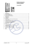
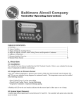
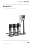
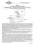
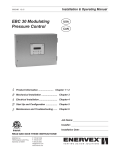
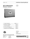
Service instructions
Hydro MPC
1.
Type identification ........................................................................................................................... 2
1.1
1.2
1.3
1.4
Nameplate ........................................................................................................................................................... 2
Nameplate, IO 351............................................................................................................................................... 3
Nameplate, CU 351 ............................................................................................................................................. 4
Configuration file label ......................................................................................................................................... 5
2.
Technical data.................................................................................................................................. 6
2.1
2.2
2.3
2.4
Pressure .............................................................................................................................................................. 6
Temperature ........................................................................................................................................................ 6
Relative humidity ................................................................................................................................................. 6
Sound pressure ................................................................................................................................................... 6
3.
CU 351 and IO 351 ........................................................................................................................... 7
3.1
3.2
Functions of terminals, CU 351 ........................................................................................................................... 7
Functions of terminals, IO 351A and IO 351B ..................................................................................................... 8
4.
Fault correction tools .................................................................................................................... 27
4.1
4.2
4.3
4.4
MPC/CU 351 LEDs and alarm relay .................................................................................................................. 27
MPC display....................................................................................................................................................... 27
R100 .................................................................................................................................................................. 32
PC Tool E-products ........................................................................................................................................... 34
5.
Factory configuration of Hydro MPC ........................................................................................... 35
5.1
5.2
Necessary equipment ........................................................................................................................................ 35
Factory configuration of Hydro MPC.................................................................................................................. 35
6.
7.
8.
Danfoss frequency converters ..................................................................................................... 47
CUE ................................................................................................................................................. 47
MGE................................................................................................................................................. 47
96646712 0609
GB
1 / 47
1. Type identification
This section show the type key, the nameplate and the codes that can appear in the variant code.
As codes can be combined, a code position may contain more than one code (letter).
Note
1.1 Nameplate
1
2
Model:
Serial No.:
3
4
Mains supply:
5 bar
Max. oper. press.:
Q Max.:
7 m3h
T Medium:
H Min.:
P
No.
Fixed speed pumps: 9
12
E-pumps:
Pilot pump:
15
oC
Un
kW
V
10
11
13
14
16
17
18
Order No.:
Options:
IP 25
Weight:
6
8 m
19
20
21
22
23
24
26 kg
Made in
28
96584435
27
Fig. 1
Pos.
TM03 1741 3105
Type:
Nameplate, booster system
Description
Pos.
Description
1
Type designation
13
Motor power in kW for pumps with frequency converter
2
Model
14
Nominal voltage in V for pumps with frequency converter
3
Serial number
15
Number of pilot pumps
4
Supply voltage
16
Motor power in kW for pilot pump
5
Maximum operating pressure in bar
17
Nominal voltage in V for pilot pump
6
Liquid temperature in °C
18
Order number
m3/h
19-24 Options
7
Maximum flow rate in
8
Minimum head in metres
25
9
Number of mains-operated pumps
26
Weight in kg
10
Motor power in kW for mains-operated pumps
27
CE-mark
11
Nominal voltage in V for mains-operated pumps
28
Country of origin
12
Number of pumps with frequency converter
2 / 47
Enclosure class
47
Type key
Example
Hydro MPC -E /G /NS 3 CRIE 5-8 (* 3x380-415 V, 50/60Hz, N, PE
Type range
Subgroups:
Pumps with integrated frequency converter (0.37-22 kW) one per pump: -E
Pumps with Grundfos CUE frequency converter (30 kW and above) one per pump: -E
Pumps with external Grundfos CUE frequency converter: -F
Mains-operated pumps (start/stop): -S
Manifold material:
: Stainless steel
/G : Galvanised steel
/OM: Other materials
Suction manifold:
: With suction manifold
/NS : Without suction manifold
Number of pumps with integrated frequency converter and pump type
Number of mains-operated pumps and pump type
Supply voltage, frequency
(* Code for custom-built solution.
IO 351A
Serial No.
96161720 - VO1
P.c.
4
100-240 Vac 50/60Hz - max. 9W
UN
!
3
5
OPEN TYPE PROCESS
CONTROL EQUIPMENT
30 XP
Made in Denmark
1
Type
Product No.
2
Nameplate, IO 351A
IO 351B
Serial No.
96161730 - VO1
P.c.
100-240 Vac 50/60Hz - max. 9W
UN
!
3
30 XP
OPEN TYPE PROCESS
CONTROL EQUIPMENT
Made in Denmark
Fig. 3
96161750
Fig. 2
TM03 1016 2205
Type
Product No.
2
5
4
TM03 1017 2205
1
96161750
1.2 Nameplate, IO 351
Nameplate, IO 351B
Pos. Description
1
Type designation
2
Product/version number
3
Permissible supply voltage, frequency
and maximum power consumption
4
Production code (year, week)
5
Serial number
Type key
Code Meaning
IO
3
5
1
IO
Input-output unit
35
Controller series
1
Model number
A
For pumps with fixed speed
B
For pumps with fixed speed and pumps in F-systems controlled by
external frequency converters or the CUE, or as input-output module
3 / 47
B
Type
Product No.
2
CU 351O
Serial No.
96161620 - VO1
P.c.
100-240 Vac 50/60Hz - max. 18W
UN
3
!
5
4
OPEN TYPE PROCESS
CONTROL EQUIPMENT
2KDO
Made in Thailand
Fig. 4
TM03 1015 2305
1
96161750
1.3 Nameplate, CU 351
Nameplate, CU 351
Pos. Description
1
Type designation
2
Product number
3
Rated voltage, frequency and power
4
Production code (year, week)
5
Serial number
Type key
Code Meaning
CU
Control unit
35
Controller series
1
Model number
O
For panel mounting
CU
3
4 / 47
5
1
O
47
1.4 Configuration file label
The configuration label shows the configuration file numbers programmed in the CU 351.
See section 5. Factory configuration of Hydro MPC.
1. Control MPC
3. Hydro MPC
1
3
4. H-MPC options 5. Pump data
2
4
5
CONFIGURATION STEPS - PLEASE FOLLOW THE NUMBERS
Fig. 5
96586126
TM03 1742 3105
2. C-MPC options
Configuration file label
Pos. Description
1
Control MPC - GSC file
2
Control MPC options - GSC files
3
Hydro MPC - GSC file
4
Hydro MPC options - GSC files
5
Pump data - GSC files
Note
A GSC (Grundfos Standard Configuration) file is a configuration data file.
5 / 47
2. Technical data
2.1 Pressure
Inlet pressure
Hydro MPC booster systems can operate with a positive inlet pressure (precharged pressure system) or with a negative
inlet pressure (i.e vacuum at the inlet manifold).
Calculation of the inlet pressure is recommended in these cases:
• Water is drawn through long pipes.
• Water is drawn from depths.
• Inlet conditions are poor.
In this manual, the term ’inlet pressure’ is defined as the pressure/vacuum which can be
measured immediately before the booster system.
Note
To avoid cavitation, make sure that there is a minimum inlet pressure on the suction side of the booster system. The
minimum inlet pressure in bar can be calculated as follows:
p s > H v + ρ × g × 10 × NPSH + H s – p b
-5
ps
= The required minimum inlet pressure in bar read from a pressure gauge on the suction side of the booster
system.
Hv
= Vapour pressure of the pumped liquid in bar.
p
= Density of the pumped liquid in kg/m3.
g
= Gravitational acceleration in m/s2.
NPSH = Net Positive Suction Head in metres head.
NPSH can be read from the NPSH curve at the maximum performance at which the pump will run.
(See installation and operating instructions for CR, CRI, CRN.)
Hs
= Safety margin = minimum 0.1 bar.
pb
= Barometric pressure in bar. Normal barometric pressure is 1.013 bar.
Maximum inlet pressure
See the CR, CRI, CRN installation and operating instructions (96462123) delivered together with this booster system.
Operating pressure
As standard, the maximum operating pressure is 16 bar.
On request, Grundfos offers Hydro MPC booster systems with a maximum operating pressure higher than 16 bar.
2.2 Temperature
Liquid temperature: 0 °C to +70 °C
Ambient temperature: 0 °C to +40 °C
2.3 Relative humidity
Max. relative humidity: 95 %
2.4 Sound pressure
For sound pressure level, see the installation and operating instructions for the CR pumps.
The sound pressure level for a number of pumps can be calculated as follows:
Lmax.
=
Lpump + (n – 1) x 3.
Lmax.
=
Maximum sound pressure level.
Lpump
=
Sound pressure level for one pump.
n
=
Number of pumps.
6 / 47
47
3. CU 351 and IO 351
3.1 Functions of terminals, CU 351
70
71
72
73
74
75
DO1, C
DO1, NO
DO1, NC
DO2, C
DO2, NO
DO2, NC
50
51
53
54
57
58
+24V
AI 1
+24V
AI 2
AI 3
GND
Common operating relay
External
GENIbus
(option)
*3
Internal
GENIbus
10 11 12 13 14 B Y A
A1 Y1 B1
PE
Neutral
Line
RS485, B
RS485, GND
DI 1
GND
DI 2
GND
DI 3
*2
RS485, A
*5
RS485, A
RS485, GND
RS485, B
*4
*1
*6
Common alarm relay
L N
TM03 1742 3105
*7
Fig. 6
Functions of terminals, CU 351
Hydro MPC default settings
*1
External start/stop
*2
Water shortage, pressure/level switch
*3
Discharge pressure
*4
Inlet pressure (deactivated if no sensor is connected)
*5
Configurable analog input (deactivated if no sensor is connected)
*6
PC Tool connection, TTL
*7
Ethernet connection
7 / 47
3.2 Functions of terminals, IO 351A and IO 351B
3.2.1 IO 351A
3C
4A
TM040220 5107
2
3A
1
Fig. 7
Terminal groups
The module can be divided into these groups:
Group
Group
Group
Group
1:
2:
3A:
3C:
4A:
Connection of supply voltage
Digital outputs 1-3
Digital inputs
GENIbus
Inputs for PTC sensor or thermal switch
3.2.2 IO 351B
5
3C
4B
4A
2
TM03 2110 3705
3B
3A
1
Fig. 8
Terminal groups
The module can be divided into these groups:
Group
Group
Group
Group
Group
1:
2:
3A:
3B:
3C:
4A, 4B:
5:
Connection of supply voltage
Digital outputs 1-3
Digital inputs
Analog inputs and outputs
GENIbus
Inputs for PTC sensor or thermal switch
Digital outputs 4-7
3.2.3 Overview of inputs and outputs of modules
Type
Analog input
Analog output
Digital input
PTC input
Digital output
Pump module A
Pump module B
IO module B
Not used
3
3
3
Not used
3
9
6
7
2
Not used
9
Not used
7
8 / 47
47
The table below shows the modules and the GENIbus number of the individual system types.
System type and number of pumps
E
ES up to four pumps
ES five to six pumps
ED up to five pumps
ED six pumps
EDF up to six pumps
EF up to three pumps
EF four to six pumps
F up to three pumps
F four to six pumps
S up to three pumps
S four to six pumps
Module required in addition to the CU 351 GENIbus number
A
B
A
B
B
B
B+B
B
B+B
A
B
General module
Operating light module
General module + operating light module
31
31
31
31
31
31
31 + 32
31
31 + 32
31
31
41
41
41 + 42
3.2.4 System type and IO module variants
System type
Maximum number
of pumps
E
6
4
ES
6
5
ED
6
EF
6
EDF
6
F
6
3
S
6
GENIbus address
Pump number
Controller/module
Module
CU 351
CU 351
IO 351A
CU 351
IO 351B
CU 351
IO 351A
CU 351
IO 351B
CU 351
IO 351B
IO 351B
CU 351
IO 351B
CU 351
IO 351B
IO 351B
CU 351
IO 351A
CU 351
IO 351B
31
31
31
31
31
32
31
31
32
31
31
IO 351B
2 x IO 351B
415)
41, 42 6)
E-Pump
1
2
3
4
5
6
1-6
1
1
1-2
1-2
-
E1)
E1)
E1)
E1)
E1)
E1)
S2)
S2)
EF3)
S2)
-
S2)
S2)
S2)
E1)
S2)
S2)
S2)
S2)
E1)
E1)
S2)
S2)
S2)
E1)
E1)
S2)
S2)
S2)
EF3) EF3) EF3)
EF3) EF3)
EF3) EF3) S2)
S2)
S2)
F/S4) F/S4) F/S4)
F/S4) F/S4) F/S4)
S2)
S2)
S2)
S2)
S2)
S2)
S2)
S2)
S2)
-
Data exchange, for instance to a PLC
E1)
Accessory
All
1) E
= 0.37 - 22 kW are E-pumps with integrated frequency converter.
30 - 55 kW are variable-speed pumps controlled by Grundfos CUE frequency converters.
2) S
= Mains-operated pump.
3) EF = Variable-speed pump controlled by an external frequency converter (not CUE).
4) F/S = Mains-operated pump or variable-speed pump controlled via a common frequency converter.
5) Interface module or operating module.
6) Interface module and operating module.
9 / 47
3.2.5 Internal and external connections
This section shows the internal and external connections. The section is split up according to the various system types.
Abbreviations used:
DI: Digital input
DO: Digital output
AO: Analog output
AI: Analog input
C: Common.
E systems, CU 351
Terminal Designation
Data
Diagram for standard configuration
10
DI 1
11
GND
10
12
DI 2
11
13
GND
CU 351
Digital input
Ext. stop
12
Water shortage
13
14
DI 3
A
RS485 A
Y
RS485 Y
14
CU 351
A
GENIbus (external)
B
RS485 B
A1
RS485 A
Y1
RS485 Y
Y
CU 351
A1
GENIbus (internal)
B1
Y1
RS485 B
L
Phase conductor
N
Neutral conductor
Option
B
B1
CU 351
L
Mains supply
N
PE
PE
70
DO1, C
71
DO1, NO
70
72
DO1, NC
71
73
DO2, C
74
DO2, NO
73
75
DO2, NC
74
75
50
+24 VDC
51
AI 1
50
53
+24 VDC
51
54
AI 2
57
AI 3
54
58
GND
57
58
PE
CU 351
System alarm
72
Digital output
System operation
CU 351
Pressure sensor
53
Analog input
10 / 47
47
ES systems
Group
Terminal Designation
L
L
N
1
N
Data
Diagram for standard configuration
Phase conductor
1 x 100-240 VAC ±10 %, 50/60 Hz
IO 351
L
Neutral conductor
N
L
N
PE
PE
2
3A
76
DO 1, 2, 3 C
IO 351
76
DO 1, 2, 3 C
76
77
DO 1 NO
79
DO 2 NO
81
DO 3 NO
10
DI 1
12
DI 2
14
DI 3
15
GND
76
Relay contact, NO
Maximum load: 240 VAC, 2 A
Minimum load: 5 VDC, 10 mA
Common
77
P2 on/off
79
P3 on/off
81
P4 on/off
IO 351
Digital input
The terminals must only be connected to voltages of maximum 16 Vrms and
22.6 Vpeak or 35 VDC.
10
Ext. stop P2
12
Ext. stop P3
14
Ext. stop P4
15
Common, GND
Fit jumpers instead of the external stops for which the controller is designed.
53
+ 24 V
55
GND
57
AI 1
3A
60
AI 2
Supply to sensor. Max. 50 mA
IO 351
53
55
Cannot be used
Input for analog signal, 0/4-20 mA or
0-10 V
57
60
The terminals must only be connected to voltages of maximum 16 Vrms and
22.6 Vpeak or 35 VDC.
A
RS485 A
A
RS485 A
Y
3C
IO 351
RS485 GND*
Y
RS485 GND*
B
RS485 B
B
RS485 B
GENIbus (internal)
(Fix the screen with a cable clamp.)
A
Y
B
CU 351
A1
Y1
B1
Functional earth
* GND is separated from other earth connections.
4A
30
PTC 1
32
PTC 2
34
35
IO 351
30
PTC P2
PTC 3
32
PTC P3
GND, PTC
34
PTC P4
35
GND, PTC
Input for PTC sensor or thermal switch
Fit jumpers if no PTC sensor or thermal switch is connected.
The terminals must only be connected to voltages of maximum 16 Vrms and
22.6 Vpeak or 35 VDC.
11 / 47
Group
3B
Terminal Designation
16
DI 4
17
GND
Data
Diagram for standard configuration
Digital input
18
AO 4
Analog output, 0-10 V
20
DI 5
Digital input
Cannot be used
21
GND
22
AO 5
Analog output, 0-10 V
24
DI 6
Digital input
25
GND
26
AO 6
42
DI 7
44
DI 8
46
DI 9
47
GND
Analog output
42
44
Digital input
Ext. stop P5
Ext. stop P6
46
47
Fit jumpers instead of the external stops for which the controller is designed.
4B
36
PTC 4
38
PTC 5
IO 351
Input for PTC sensor or thermal switch
36
PTC P5
PTC P6
40
PTC 6
38
41
GND, PTC
40
Fit jumpers if no PTC sensor or thermal switch is connected.
41
GND, PTC
The terminals must only be connected to voltages of maximum 16 Vrms and
22.6 Vpeak or 35 VDC.
5
82
DO 4 NO
83
DO 4 C
83
DO 4 C
84
DO 5 NO
85
DO 5 C
85
DO 5 C
86
DO 6 NO
87
DO 6 C
87
DO 6 C
88
DO 7 NO
89
DO 7 C
IO 351
Relay contact, NO
Maximum load: 240 VAC, 2 A
Minimum load: 5 VDC, 10 mA
12 / 47
47
82
83
83
84
85
85
86
87
87
88
89
P5 on/off
Common
P6 on/off
Common
ED systems
Group
Terminal Designation
L
L
N
1
N
Data
Diagram for standard configuration
Phase conductor
1 x 100-240 VAC ±10 %, 50/60 Hz
IO 351
L
Neutral conductor
N
L
N
PE
PE
2
3A
76
DO 1, 2, 3 C
76
DO 1, 2, 3 C
76
77
DO 1 NO
76
79
DO 2 NO
81
DO 3 NO
10
DI 1
12
DI 2
14
DI 3
15
GND
IO 351
Relay contact, NO
Maximum load: 240 VAC, 2A
Minimum load: 5 VDC, 10 mA
Common
77
P3 on/off
79
P4 on/off
81
P5 on/off
IO 351
Digital input
The terminals must only be connected to voltages of maximum 16 Vrms
and 22.6 Vpeak or 35 VDC.
10
Ext. stop P3
12
Ext. stop P4
14
Ext. stop P5
15
Common, GND
Fit jumpers instead of the external stops for which the controller is
designed.
53
+ 24 V
55
GND
57
AI 1
3A
60
AI 2
Supply to sensor. Max. 50 mA
IO 351
53
55
Cannot be used
Input for analog signal, 0/4-20 mA or
0-10 V
57
60
The terminals must only be connected to voltages of maximum 16 Vrms
and 22.6 Vpeak or 35 VDC.
3C
A
RS485 A
A
RS485 A
Y
RS485 GND*
Y
RS485 GND*
B
RS485 B
B
RS485 B
IO 351
GENIbus (internal)
(Fix the screen with a cable clamp.)
A
Y
B
CU 351
A1
Y1
B1
Functional earth
* GND is separated from other earth connections.
4A
30
PTC 1
32
PTC 2
34
35
IO 351
30
PTC P3
PTC 3
32
PTC P4
GND, PTC
34
PTC P5
35
GND, PTC
Input for PTC sensor or thermal switch
Fit jumpers if no PTC sensor or thermal switch is connected.
The terminals must only be connected to voltages of maximum 16 Vrms
and 22.6 Vpeak or 35 VDC.
13 / 47
Group
3B
Terminal Designation
16
DI 4
17
GND
Data
Diagram for standard configuration
Digital input
18
AO 4
Analog output, 0-10 V
20
DI 5
Digital input
Cannot be used
21
GND
22
AO 5
Analog output, 0-10 V
24
DI 6
Digital input
25
GND
26
AO 6
42
DI 7
44
DI 8
46
DI 9
47
GND
Analog output
42
44
Digital input
Ext. stop P6
46
47
Fit jumpers instead of the external stops for which the controller is
designed.
4B
36
PTC 4
38
PTC 5
40
PTC 6
38
41
GND, PTC
40
IO 351
Input for PTC sensor or thermal switch
Fit jumpers if no PTC sensor or thermal switch is connected.
36
PTC P6
41
GND, PTC
The terminals must only be connected to voltages of maximum 16 Vrms
and 22.6 Vpeak or 35 VDC.
5
82
DO 4 NO
83
DO 4 C
83
DO 4 C
84
DO 5 NO
85
DO 5 C
85
DO 5 C
86
DO 6 NO
87
DO 6 C
87
DO 6 C
88
DO 7 NO
89
DO 7 C
IO 351
82
83
83
84
85
85
86
87
87
88
89
Relay contact, NO
Maximum load: 240 VAC, 2 A
Minimum load: 5 VDC, 10 mA
14 / 47
47
P6 on/off
Common
EDF systems
Group
Terminal Designation
L
L
N
1
N
Data
Diagram for standard configuration
Phase conductor
1 x 100-240 VAC ±10 %, 50/60 Hz
IO 351
L
Neutral conductor
N
L
N
PE
PE
2
3A
76
DO 1, 2, 3 C
76
DO 1, 2, 3 C
76
77
DO 1 NO
76
79
DO 2 NO
81
DO 3 NO
10
DI 1
12
DI 2
14
DI 3
15
GND
IO 351
Relay contact, NO
Maximum load: 240 VAC, 2A
Minimum load: 5 VDC, 10 mA
Common
77
P4 on/off, mains
79
P5 on/off, mains
81
P6 on/off, mains
IO 351
Digital input
The terminals must only be connected to voltages of maximum 16 Vrms and
22.6 Vpeak or 35 VDC.
10
Ext. stop P1
12
Ext. stop P2
14
Ext. stop P3
15
Common, GND
Fit jumpers instead of the external stops for which the controller is designed.
53
+ 24 V
55
GND
57
AI 1
3A
60
AI 2
Supply to sensor. Max. 50 mA
IO 351
53
55
Cannot be used
Input for analog signal, 0/4-20 mA or
0-10 V
57
60
The terminals must only be connected to voltages of maximum 16 Vrms and
22.6 Vpeak or 35 VDC.
A
RS485 A
A
RS485 A
Y
3C
IO 351
RS485 GND*
Y
RS485 GND*
B
RS485 B
B
RS485 B
GENIbus (internal)
(Fix the screen with a cable clamp.)
A
Y
B
CU 351
A1
Y1
B1
Functional earth
* GND is separated from other earth connections.
4A
30
PTC 1
32
PTC 2
34
35
IO 351
30
PTC P1
PTC 3
32
PTC P2
GND, PTC
34
PTC P3
35
GND, PTC
Input for PTC sensor or thermal switch
Fit jumpers if no PTC sensor or thermal switch is connected.
The terminals must only be connected to voltages of maximum 16 Vrms and
22.6 Vpeak or 35 VDC.
15 / 47
Group
3B
Terminal Designation
Data
Diagram for standard configuration
16
DI 4
17
GND
Digital input
18
AO 4
Analog output, 0-10 V
20
DI 5
Digital input
IO 351
VFD1, ready
VFD1, GND
VFD1, speed
VFD2, ready
VFD2, GND
VFD2, speed
Analog output
16
17
18
20
21
22
23
24
25
26
42
44
Ext. stop P4
Digital input
21
GND
22
AO 5
Analog output, 0-10 V
24
DI 6
Digital input
25
GND
26
AO 6
42
DI 7
44
DI 8
46
DI 9
47
GND
46
47
Ext. stop P5
Ext. stop P6
Common, GND
Fit jumpers instead of the external stops for which the controller is designed.
4B
36
PTC 4
38
PTC 5
IO 351
Input for PTC sensor or thermal switch
36
PTC P4
PTC P5
40
PTC 6
38
41
GND, PTC
40
PTC P6
41
GND, PTC
Fit jumpers if no PTC sensor or thermal switch is connected.
The terminals must only be connected to voltages of maximum 16 Vrms and
22.6 Vpeak or 35 VDC.
5
82
DO 4 NO
83
DO 4 C
83
DO 4 C
84
DO 5 NO
85
DO 5 C
85
DO 5 C
86
DO 6 NO
87
DO 6 C
87
DO 6 C
88
DO 7 NO
89
DO 7 C
IO 351
Relay contact, NO
Maximum load: 240 VAC, 2 A
Minimum load: 5 VDC, 10 mA
16 / 47
47
82
83
83
84
85
85
86
87
87
88
89
VFD1, start
Common
VFD2, start
Common
P3 on/off, mains
Common
EF systems, module B1
Group
Terminal Designation
L
L
N
1
N
Data
Diagram for standard configuration
Phase conductor
1 x 100-240 VAC ±10 %, 50/60 Hz
IO 351
L
Neutral conductor
N
L
N
PE
PE
2
76
DO 1, 2, 3 C
76
DO 1, 2, 3 C
77
DO 1 NO
79
DO 2 NO
81
IO 351
76
76
Relay contact, NO
Maximum load: 240 VAC, 2A
Minimum load: 5 VDC, 10 mA
77
Cannot be used
79
DO 3 NO
81
3A
10
DI 1
12
DI 2
14
DI 3
15
GND
IO 351
Digital input
The terminals must only be connected to voltages of maximum 16 Vrms and
22.6 Vpeak or 35 VDC.
10
Ext. stop P1
12
Ext. stop P2
14
Ext. stop P3
15
Common, GND
Fit jumpers instead of the external stops for which the controller is designed.
53
+ 24 V
55
GND
57
AI 1
3A
60
AI 2
Supply to sensor. Max. 50 mA
IO 351
53
55
Cannot not be used
Input for analog signal, 0/4-20 mA or
0-10 V
57
60
The terminals must only be connected to voltages of maximum 16 Vrms and
22.6 Vpeak or 35 VDC.
3C
A
RS485 A
A
RS485 A
Y
RS485 GND*
Y
RS485 GND*
B
RS485 B
B
RS485 B
IO 351
GENIbus (internal)
(Fix the screen with a cable clamp.)
A
Y
B
CU 351
A1
Y1
B1
Functional earth
* GND is separated from other earth connections.
4A
30
PTC 1
32
PTC 2
34
35
IO 351
30
PTC P1
PTC 3
32
PTC P2
GND, PTC
34
PTC P3
35
GND, PTC
Input for PTC sensor or thermal switch
Fit jumpers if no PTC sensor or thermal switch is connected.
The terminals must only be connected to voltages of maximum 16 Vrms and
22.6 Vpeak or 35 VDC.
17 / 47
Group
3B
4B
Terminal Designation
Data
Diagram for standard configuration
16
DI 4
17
GND
Digital input
18
AO 4
Analog output, 0-10 V
20
DI 5
Digital input
IO 351
21
GND
22
AO 5
Analog output, 0-10 V
24
DI 6
Digital input
25
GND
26
AO 6
42
DI 7
44
DI 8
46
DI 9
16
17
18
20
21
22
23
24
25
26
Analog output
VFD1, ready
VFD1, GND
VFD1, speed
VFD2, ready
VFD2, GND
VFD2, speed
VFD3, ready
VFD3, GND
VFD3, speed
42
44
46
47
Digital input
47
GND
36
PTC 4
38
PTC 5
40
PTC 6
38
41
GND, PTC
40
IO 351
Input for PTC sensor or thermal switch
Fit jumpers if no PTC sensor or thermal switch is connected.
36
41
The terminals must only be connected to voltages of maximum 16 Vrms and
22.6 Vpeak or 35 VDC.
5
82
DO 4 NO
83
DO 4 C
83
DO 4 C
84
DO 5 NO
85
DO 5 C
85
DO 5 C
86
DO 6 NO
87
DO 6 C
87
DO 6 C
88
DO 7 NO
89
DO 7 C
IO 351
Relay contact, NO
Maximum load: 240 VAC, 2 A
Minimum load: 5 VDC, 10 mA
18 / 47
47
82
83
83
84
85
85
86
87
87
88
89
VFD1, start
Common
VFD2, start
Common
VFD3, start
Common
EF systems, module B2
Group
Terminal Designation
L
L
N
1
N
Data
Diagram for standard configuration
Phase conductor
1 x 100-240 VAC ±10 %, 50/60 Hz
IO 351
L
Neutral conductor
N
L
N
PE
PE
2
76
DO 1, 2, 3 C
76
DO 1, 2, 3 C
77
DO 1 NO
79
DO 2 NO
81
IO 351
76
76
Relay contact, NO
Maximum load: 240 VAC, 2A
Minimum load: 5 VDC, 10 mA
77
Cannot be used
79
DO 3 NO
81
3A
10
DI 1
12
DI 2
14
DI 3
15
GND
IO 351
Digital input
The terminals must only be connected to voltages of maximum 16 Vrms and
22.6 Vpeak or 35 VDC.
10
Ext. stop P4
12
Ext. stop P5
14
Ext. stop P6
15
Common, GND
Fit jumpers instead of the external stops for which the controller is designed.
53
+ 24 V
55
GND
57
AI 1
3A
60
AI 2
Supply to sensor. Max. 50 mA
IO 351
53
55
Cannot be used
Input for analog signal, 0/4-20 mA or
0-10 V
57
60
The terminals must only be connected to voltages of maximum 16 Vrms and
22.6 Vpeak or 35 VDC.
3C
A
RS485 A
A
RS485 A
Y
RS485 GND*
Y
RS485 GND*
B
RS485 B
B
RS485 B
IO 351
GENIbus (internal)
(Fix the screen with a cable clamp.)
A
Y
B
CU 351
A1
Y1
B1
Functional earth
* GND is separated from other earth connections.
4A
30
PTC 1
32
PTC 2
34
35
IO 351
30
PTC P4
PTC 3
32
PTC P5
GND, PTC
34
PTC P6
35
GND, PTC
Input for PTC sensor or thermal switch
Fit jumpers if no PTC sensor or thermal switch is connected.
The terminals must only be connected to voltages of maximum 16 Vrms and
22.6 Vpeak or 35 VDC.
19 / 47
Group
3B
4B
Terminal Designation
Data
Diagram for standard configuration
16
DI 4
17
GND
Digital input
18
AO 4
Analog output, 0-10 V
20
DI 5
Digital input
IO 351
Analog output
16
17
18
20
21
22
23
24
25
26
Digital input
42
44
21
GND
22
AO 5
Analog output, 0-10 V
24
DI 6
Digital input
25
GND
26
AO 6
42
DI 7
44
DI 8
46
DI 9
VFD4, ready
VFD4, GND
VFD4, speed
VFD5, ready
VFD5, GND
VFD5, speed
VFD6, ready
VFD6, GND
VFD6, speed
46
47
47
GND
36
PTC 4
38
PTC 5
40
PTC 6
38
41
GND, PTC
40
IO 351
Input for PTC sensor or thermal switch
Fit jumpers if no PTC sensor or thermal switch is connected.
36
41
The terminals must only be connected to voltages of maximum 16 Vrms and
22.6 Vpeak or 35 VDC.
5
82
DO 4 NO
83
DO 4 C
83
DO 4 C
84
DO 5 NO
85
DO 5 C
85
DO 5 C
86
DO 6 NO
87
DO 6 C
87
DO 6 C
88
DO 7 NO
89
DO 7 C
IO 351
Relay contact, NO
Maximum load: 240 VAC, 2 A
Minimum load: 5 VDC, 10 mA
20 / 47
47
82
83
83
84
85
85
86
87
87
88
89
VFD4, start
Common
VFD5, start
Common
VFD6, start
Common
F systems, module B1
Group
Terminal Designation
L
L
N
1
N
Data
Diagram for standard configuration
Phase conductor
1 x 100-240 VAC ±10 %, 50/60 Hz
IO 351
L
Neutral conductor
N
L
N
PE
PE
2
3A
76
DO 1, 2, 3 C
76
DO 1, 2, 3 C
77
DO 1 NO
79
DO 2 NO
81
DO 3 NO
10
DI 1
12
DI 2
14
DI 3
15
GND
IO 351
76
76
Relay contact, NO
Maximum load: 240 VAC, 2A
Minimum load: 5 VDC, 10 mA
Common
77
P1 on/off, mains
79
P2 on/off, mains
81
P3 on/off, mains
IO 351
Digital input
The terminals must only be connected to voltages of maximum 16 Vrms and
22.6 Vpeak or 35 VDC.
10
Ext. stop P1
12
Ext. stop P2
14
Ext. stop P3
15
Common, GND
Fit jumpers instead of the external stops for which the controller is designed.
53
+ 24 V
55
GND
57
AI 1
3A
60
AI 2
Supply to sensor. Max. 50 mA
IO 351
53
55
Cannot be used
Input for analog signal, 0/4-20 mA or
0-10 V
57
60
The terminals must only be connected to voltages of maximum 16 Vrms and
22.6 Vpeak or 35 VDC.
A
RS485 A
A
RS485 A
Y
3C
IO 351
RS485 GND*
Y
RS485 GND*
B
RS485 B
B
RS485 B
GENIbus (internal)
(Fix the screen with a cable clamp.)
A
Y
B
CU 351
A1
Y1
B1
Functional earth
* GND is separated from other earth connections.
4A
30
PTC 1
32
PTC 2
34
35
IO 351
30
PTC P1
PTC 3
32
PTC P2
GND, PTC
34
PTC P3
35
GND, PTC
Input for PTC sensor or thermal switch
Fit jumpers if no PTC sensor or thermal switch is connected.
The terminals must only be connected to voltages of maximum 16 Vrms and
22.6 Vpeak or 35 VDC.
21 / 47
Group
3B
Terminal Designation
Data
Diagram for standard configuration
16
DI 4
17
GND
Digital input
18
AO 4
Analog output, 0-10 V
20
DI 5
Digital input
IO 351
Analog output
16
17
18
20
21
22
23
24
25
26
Digital input
42
44
21
GND
22
AO 5
Analog output, 0-10 V
24
DI 6
Digital input
25
GND
26
AO 6
42
DI 7
44
DI 8
46
DI 9
47
GND
46
47
VFD1, GND
VFD1, speed
VFD, ready
VFD, GND
Fit jumpers instead of the external stops for which the controller is designed.
4B
36
PTC 4
38
PTC 5
40
PTC 6
38
41
GND, PTC
40
IO 351
Input for PTC sensor or thermal switch
Fit jumpers if no PTC sensor or thermal switch is connected.
36
41
The terminals must only be connected to voltages of maximum 16 Vrms and
22.6 Vpeak or 35 VDC.
5
82
DO 4 NO
83
DO 4 C
83
DO 4 C
84
DO 5 NO
85
DO 5 C
85
DO 5 C
86
DO 6 NO
87
DO 6 C
87
DO 6 C
88
DO 7 NO
89
DO 7 C
IO 351
Relay contact, NO
Maximum load: 240 VAC, 2 A
Minimum load: 5 VDC, 10 mA25
22 / 47
47
82
83
83
84
85
85
86
87
87
88
89
P1 on/off, VFD
Common
P2 on/off, VFD
Common
P3 on/off, VFD
Common
VFD start
Common
F systems, module B2
Group
Terminal Designation
L
L
N
1
N
Data
Diagram for standard configuration
Phase conductor
1 x 100-240 VAC ±10 %, 50/60 Hz
IO 351
L
Neutral conductor
N
L
N
PE
PE
2
3A
76
DO 1, 2, 3 C
76
DO 1, 2, 3 C
76
77
DO 1 NO
76
79
DO 2 NO
81
DO 3 NO
10
DI 1
12
DI 2
14
DI 3
15
GND
IO 351
Relay contact, NO
Maximum load: 240 VAC, 2A
Minimum load: 5 VDC, 10 mA
Common
77
P4 on/off, mains
79
P5 on/off, mains
81
P6 on/off, mains
IO 351
Digital input
The terminals must only be connected to voltages of maximum 16 Vrms and
22.6 Vpeak or 35 VDC.
10
Ext. stop P4
12
Ext. stop P5
14
Ext. stop P6
15
Common, GND
Fit jumpers instead of the external stops for which the controller is designed.
53
+ 24 V
55
GND
57
AI 1
3A
60
AI 2
Supply to sensor. Max. 50 mA
IO 351
53
55
Cannot be used
Input for analog signal, 0/4-20 mA or
0-10 V
57
60
The terminals must only be connected to voltages of maximum 16 Vrms and
22.6 Vpeak or 35 VDC.
A
RS485 A
A
RS485 A
Y
3C
IO 351
RS485 GND*
Y
RS485 GND*
B
RS485 B
B
RS485 B
GENIbus (internal)
(Fix the screen with a cable clamp.)
A
Y
B
CU 351
A1
Y1
B1
Functional earth
* GND is separated from other earth connections.
4A
30
PTC 1
32
PTC 2
34
35
IO 351
30
PTC P4
PTC 3
32
PTC P5
GND, PTC
34
PTC P6
35
GND, PTC
Input for PTC sensor or thermal switch
Fit jumpers if no PTC sensor or thermal switch is connected.
The terminals must only be connected to voltages of maximum 16 Vrms and
22.6 Vpeak or 35 VDC.
23 / 47
Group
3B
4B
Terminal Designation
Data
Diagram for standard configuration
16
DI 4
17
GND
Digital input
18
AO 4
Analog output, 0-10 V
20
DI 5
Digital input
IO 351
Analog output
16
17
18
20
21
22
23
24
25
26
Digital input
42
44
21
GND
22
AO 5
Analog output, 0-10 V
24
DI 6
Digital input
25
GND
26
AO 6
42
DI 7
44
DI 8
46
DI 9
46
47
47
GND
36
PTC 4
38
PTC 5
40
PTC 6
38
41
GND, PTC
40
IO 351
Input for PTC sensor or thermal switch
36
41
Fit jumpers if no PTC sensor or thermal switch is connected.
The terminals must only be connected to voltages of maximum 16 Vrms and
22.6 Vpeak or 35 VDC.
5
82
DO 4 NO
83
DO 4 C
83
DO 4 C
84
DO 5 NO
85
DO 5 C
85
DO 5 C
86
DO 6 NO
87
DO 6 C
87
DO 6 C
88
DO 7 NO
89
DO 7 C
IO 351
Relay contact, NO
Maximum load: 240 VAC, 2 A
Minimum load: 5 VDC, 10 mA
24 / 47
47
82
83
83
84
85
85
86
87
87
88
89
P4 on/off, VFD
Common
P5 on/off, VFD
Common
P6 on/off, VFD
Common
S systems
Group
Terminal Designation
L
L
N
1
N
Data
Diagram for standard configuration
Phase conductor
1 x 100-240 VAC ±10 %, 50/60 Hz
IO 351
L
Neutral conductor
N
L
N
PE
PE
2
3A
76
DO 1, 2, 3 C
76
DO 1, 2, 3 C
77
DO 1 NO
79
DO 2 NO
81
DO 3 NO
10
DI 1
12
DI 2
14
DI 3
15
GND
IO 351
76
76
Relay contact, NO
Maximum load: 240 VAC, 2A
Minimum load: 5 VDC, 10 mA
Common
77
P1 on/off, mains
79
P2 on/off, mains
81
P3 on/off, mains
IO 351
Digital input
The terminals must only be connected to voltages of maximum 16 Vrms and
22.6 Vpeak or 35 VDC.
10
Ext. stop P1
12
Ext. stop P2
14
Ext. stop P3
15
Common, GND
Fit jumpers instead of the external stops for which the controller is designed.
53
+ 24 V
55
GND
57
AI 1
3A
60
AI 2
Supply to sensor. Max. 50 mA
IO 351
53
55
Cannot be used
Input for analog signal, 0/4-20 mA or
0-10 V
57
60
The terminals must only be connected to voltages of maximum 16 Vrms and
22.6 Vpeak or 35 VDC.
A
RS485 A
A
RS485 A
Y
3C
IO 351
RS485 GND*
Y
RS485 GND*
B
RS485 B
B
RS485 B
GENIbus (internal)
(Fix the screen with a cable clamp.)
A
Y
B
CU 351
A1
Y1
B1
Functional earth
* GND is separated from other earth connections.
4A
30
PTC 1
32
PTC 2
34
35
IO 351
30
PTC P1
PTC 3
32
PTC P2
GND, PTC
34
PTC P3
35
GND, PTC
Input for PTC sensor or thermal switch
Fit jumpers if no PTC sensor or thermal switch is connected.
The terminals must only be connected to voltages of maximum 16 Vrms and
22.6 Vpeak or 35 VDC.
25 / 47
Group
3B
Terminal Designation
Data
Diagram for standard configuration
16
DI 4
17
GND
Digital input
18
AO 4
Analog output, 0-10 V
20
DI 5
Digital input
IO 351
Analog output
16
17
18
20
21
22
23
24
25
26
Digital input
42
44
21
GND
22
AO 5
Analog output, 0-10 V
24
DI 6
Digital input
25
GND
26
AO 6
42
DI 7
44
DI 8
46
DI 9
47
GND
46
47
Ext. stop P4
Ext. stop P5
Ext. stop P6
Common, GND
Fit jumpers instead of the external stops for which the controller is designed.
4B
36
PTC 4
38
PTC 5
IO 351
Input for PTC sensor or thermal switch
36
PTC P4
PTC P5
40
PTC 6
38
41
GND, PTC
40
PTC P6
41
GND, PTC
Fit jumpers if no PTC sensor or thermal switch is connected.
The terminals must only be connected to voltages of maximum 16 Vrms and
22.6 Vpeak or 35 VDC.
5
82
DO 4 NO
83
DO 4 C
83
DO 4 C
84
DO 5 NO
85
DO 5 C
85
DO 5 C
86
DO 6 NO
87
DO 6 C
87
DO 6 C
88
DO 7 NO
89
DO 7 C
IO 351
Relay contact, NO
Maximum load: 240 VAC, 2 A
Minimum load: 5 VDC, 10 mA
82
83
83
84
85
85
86
87
87
88
89
P4, on/off
Common
P5, on/off
Common
P6, on/off
Common
3.2.6 CU 351 and IO 351 installation and operating instructions
See WinCAPS or WebCAPS | Service | Hydro MPC | CU 351 or IO 351 | installation and operating instructions.
26 / 47
47
4. Fault correction tools
4.1 MPC/CU 351 LEDs and alarm relay
See WinCAPS or WebCAPS | Service | Hydro MPC | installation and operating instructions.
4.2 MPC display
4.2.1 Status
The first status display is shown below. This display is shown when the Hydro MPC is switched on, and it appears when
the buttons of the control panel have not been touched for 15 minutes.
F
G
H
E
A
B
D
Fig. 9
TM03 8947 3807
C
Status menu
Description
No settings can be made in this menu.
The current value (process value, PV) of the control parameter, usually the discharge pressure, is shown in the upper
right corner (G) together with the selected setpoint (SP) (H).
The upper half of the display (A) shows a graphic illustration of the Hydro MPC booster system and part of the system.
The selected measuring parameters are shown with sensor symbol and current value. The current value of the control
parameter, usually the discharge pressure, is shown under the pressure sensor symbol.
The lower display half (B) shows
• the latest current alarm, if any, and the fault cause together with the fault code in brackets
• system status with current operating mode and current source
• pump status with current operating mode and manual/auto.
Note: If a fault has occurred, the symbol
will be shown in the alarm line (C) together with the cause and alarm code,
for instance Overtemperature (64).
• If the fault is related to one of the pumps, the symbol
will also be shown in front of the status line (D) of the pump
in question. At the same time the symbol
will be flashing instead of the pump symbol (E). The symbol
will be
shown to the right in the top line of the display (F). As long as a fault is present, this symbol will be shown in the top
line of all displays. Note: Selecting "System" or pump indicating the alarm bell does not lead to the alarm indication, but to a status!
• Display "3.1 - Current alarms" is shown. Go to the alarm list and troubleshoot accordingly.
To open a menu line, mark the line with
or
, and press
.
The display makes it possible to open status displays showing
• current alarms
• system status
• status of each pump.
27 / 47
TM03 2292 3707
Alarm log (3.2)
The alarm log can store up to 24 warnings and alarms.
Fig. 10 Alarm log
Description
Here warnings and alarms are shown.
For every warning or alarm, the following is shown:
• Whether it is a warning
or an alarm .
• Where the fault occurred. System, Pump 1, Pump 2, etc.
• In case of input-related faults, the input is shown.
• What the cause of the fault is, and the alarm code in brackets: Water shortage (214), Max. pressure (210), etc.
• When the fault occurred: Date and time.
• When the fault disappeared: Date and time. If the fault still exists, date and time are shown as --...--.
• The latest warning/alarm is shown at the top of the display.
4.2.2 Passwords
Passwords can be set to prevent unauthorized change of settings in the menus Operation and Settings.
See the Hydro MPC Installation and operating instructions.
Both passwords are deactivated. If a password is activated, the factory setting is "1234".
Service passwords
If a customer password is set and not available for a Grundfos service engineer, the booster system can be unlocked
by using the Grundfos service code "6814". Please protect this code, and avoid unauthorized to know this code.
28 / 47
47
4.2.3 Alarm list
Check all current alarm codes before starting the fault correction.
MPC alarm indication
*Protocol description
Phase failure, pump
Associated
Alarm
device and
Description/cause
code
device number
2
Pump 1-6
Undervoltage
7
Pump 1-6
Undervoltage, pump
40
Pump 1-6
Undervoltage, pump
42
Pump 1-6
Undervoltage, pump
73
Pump 1-6
Overvoltage, pump
32
Pump 1-6
Overload, associated
device
48
Pump 1-6
Overload, associated
device
50
Pump 1-6
Overload, associated
device
51
Pump 1-6
Overload, associated
device
54
Pump 1-6
Too high motor
temperature
65,
70
Pump 1-6
Too high motor
temperature
67
Pump 1-6
Other fault, associated
device
76
Pump 1-6
Limit 1 exceeded
190
Measured
parameter
HSD = hardware shutdown.
There has been a fault,
and the permissible
number of restarts for
the fault type has been
exceeded.
• Fault in mains
supply.
• Terminal box
defective.
Mains voltage is too low
at start.
Faulty mains voltage at
the time of cutting in the
terminal box.
- Fall in mains supply.
- Mains supply failure
while motor is running.
Mains voltage is too high
at start.
Heavy overload has
caused software shutdown (SSD).
MPF = motor protection
function.
The built-in motor
protection has detected
a sustained overload
(MPF 60 sec. limit).
Heavy overload (Imax.
very high).
Pump blocked at start.
The built-in motor
protection has detected
a transitory overload
(MPF 3 sec. limit).
PTC sensor in the motor
has signalled
overtemperature.
Remedy
Check that all three
mains phases are within
a 15 V window.
• Restore mains
supply.
• Replace terminal
box.
Bring voltage back to
prescribed level.
Restore proper mains
supply.
Restore proper mains
supply.
Bring voltage back to
prescribed level.
Check and possibly
reduce the load.
Check and possibly
reduce load/improve
cooling.
Alarm/warning
Action type
Auto
Warning
Auto
Warning
Auto
Warning
Auto
Warning
Auto
Warning
Auto
Warning
Auto
Warning
Auto
Warning
Auto
Warning
Auto
Warning
Auto
Warning
Auto
Warning
Auto
Warning
Deblock the pump.
Check and possibly
reduce load/improve
cooling.
Check and possibly
reduce load/improve
cooling.
Check and possibly
reduce load/improve
Terminal box has
cooling.
indicated
(Temperature during
overtemperature.
operation can be read via
PC Tool E-products.)
Try to reset the fault:
1. Switch off the
supply voltage.
2. Wait until all diodes
Internal communication
are out.
error has occurred in the
3. Switch in the supply
pump.
voltage.
If this does not remedy
the fault, replace the
terminal box.
The measured parameRemove the cause of the
ter has exceed the limit
fault.
set.
29 / 47
Reset
type 1)
Alarm/warning
Auto/
manual Stop/unchanged
MPC alarm indication
*Protocol description
Associated
Alarm
device and
Description/cause
code
device number
Limit 2 exceeded
191
Measured
parameter
Pressure relief
219
System
Pressure build-up fault
215
System
Pumps outside duty
range
208
System
Pilot pump fault
Water shortage
*Water shortage
Water shortage
*Water shortage
216
Pilot pump
Remedy
The measured parameter has exceed the limit
set.
The monitored pressure
could not be reduced
sufficiently.
The pressure set cannot
be reached within the
configured time.
214
Pilot pump fault.
The pre-pressure switch
detects water shortage.
Pressure high
*Pressure above max.
pressure
Pressure low
*Pressure below min.
pressure
Check limit and pipes.
- Check wires.
- Check the pump.
1. Check the actual
pressure and the
corresponding
settings.
2. Check the sensor/
switch, wiring and
input according to
the wiring diagram.
3. Check the sensor/
switch.
Unchanged
Auto
Warning
Auto/
manual
Auto/
manual
Unchanged
Stop
Warning
Unchanged
Alarm
Auto/
manual
204
Warning
Alarm
The operating pressure
is below the
Booster system programmable lowpressure alarm limit.
Primary sensor
and/or
redundant
sensor
Warning
Auto/
manual
211
003
Unchanged
Alarm/warning
Auto/
manual Stop/unchanged
210
External fault
*External fault
Action type
Warning
Auto
Auto/
manual
203
Alarm/warning
Alarm/warning
Auto/
manual Stop/unchanged
The operating pressure
is above the
programmable highpressure alarm limit.
Alarm, all pumps
*Alarm, all pumps
Dissimilar sensor signals
*Dissimilar sensor
signals
Reduce the pressure to
below the limit.
The pump is running outCheck the system.
side the defined range.
The pre-pressure (or the
level in the feed tank) is
below its programmable
warning limit.
The pre-pressure (or the
level in the feed tank) is
below its programmable
alarm limit.
206
Remove the cause of the
fault.
Reset
type 1)
Fast stop
(overrule min.
seq. time)
Alarm/warning
Stop/unchanged
Troubleshoot according
to the alarm message/
code:
All pumps, set to Auto,
Alarm
1. System.
are stopped due to a
2. Pumps installed.
pump alarm.
Use fault-finding for
Auto
the pump.
1. Check the GENIbus
wires, for instance
Pumps are not indicating
Stop
connection and
alarm.
polarisation.
The fault reading can be
Alarm/warning
reset by means of the
The digital input set to
Auto/
R100 when the digital
’external fault’ has been
input is no longer closed. manual
or is still closed.
Stop/unchanged
Reset by pressing "+" or
"-".
1. Check the wiring
Warning
and input according
Primary feedback sensor
to the wiring
value (pressure) is
Auto
diagram.
inconsistent with
2. Check the sensor
redundant feedback
Unchanged
output according to
sensor value.
the value measured.
30 / 47
47
MPC alarm indication
*Protocol description
Fault, primary sensor
*Closed loop feedback
sensor signal fault
Fault sensor
*General (measurement)
sensor signal fault
Internal fault CU 351
*Real time clock out of
order
Fault, ethernet
*Ethernet: No address
from DHCP server
Fault, ethernet
*Ethernet: Auto disabled
due to misuse
FLASH parameter
verification error
*FLASH parameter
verification error
Other fault, associated
device
IO 351 internal fault
*Hardware fault type 2
VFD not ready
*VFD not ready
Communication fault
*Pump communication
fault
Device alarms
1) Reset
type, either:
Associated
Alarm
device and
Description/cause
code
device number
Remedy
A fault in the sensor
assigned to the
feedback control has
been detected.
1. Check the wiring
and input according
to the wiring
diagram.
2. Check the sensor
output according to
the value measured.
Error in the settings of
the sensor assigned to
the controller.
Check the primary
sensor settings.
The signal (for instance
4 to 20 mA) from one of
the analog sensors is
outside the selected
signal range.
1. Check the wiring
and input according
to the wiring
diagram.
2. Check the sensor
output according to
the measured value.
157
The real-time clock in
the CU 351 is out of
order.
Replace the CU 351.
231
No address from DHCP
server.
089
088
232
Primary sensor
CU 351
IO 351B as
IO module
CU 351
Auto-disabled due to
misuse.
Alarm/warning
Action type
Alarm
Auto
Stop
Warning
Auto
Unchanged
Warning
Communication error.
Contact the system
integrator.
Auto
Unchanged
083
Verification error in the
Replace the CU 351.
CU 351 FLASH memory.
83
Setting data not correct.
Hardware fault in the
IO 351A.
080
IO 351
Hardware fault in the
IO 351B.
213
010
Pump 1-6
CU 351
Pump 1-6
IO 351
From
Pump 1-6
device
Other fault, associated
device
See Current alarms, and
identify the faulty IO 351
module from the alarm
message. Replace the
module.
1. Check for VFD
alarm.
The VFD signal relay do
2. Check the wiring
not release the VFD for
and input according
operation.
to the wiring
diagram.
See Current alarms, and
identify the faulty device
from the alarm message.
1. Check power
No GENIbus
supply.
communication with a
2. Check GENIbus
device connected to the
cable connection.
CU 351.
3. Check that the
device GENIbus
number is correct,
using the R100.
The device is in alarm.
See Current alarms, and
identify the faulty device
from the alarm message.
1. Fault-find according
to the Service
instructions for the
device.
• "Auto acknowledge" (auto)
• "Auto acknowledge" or "Manual acknowledge" (auto/man)
2)
Reset
type 1)
System goes to operating mode "Stop" (no delay (< 0.5 s) between pump disconnections).
31 / 47
Warning
Warning
Auto
Unchanged
Warning
Auto
Unchanged
Warning
Auto
Unchanged
Warning
Auto
Unchanged
4.3 R100
4.3.1 R100 menu for Hydro MPC, IO 351A and IO 351B (configured as pump module)
Displays marked like
this can only be opened
by means of the service
code.
32 / 47
47
4.3.2 R100 menu for Hydro MPC, IO 351B
(configured as general-purpose installation and operating instructions)
Displays marked like
this can only be opened
by means of the service
code.
33 / 47
4.4 PC Tool E-products
The Grundfos PC Tool E-products, version V05 or later, supports the Hydro MPC control and the components included.
A detailed PC Tool Help assistant is available in the tool program, and a user manual can be printed in PDF format from
the tool. The tool can be connected to the CU 351 control unit of the Hydro MPC booster system and communicate with
IO units and MGE pumps. The network list of the tool shows the units which are capable of communicating with the
application in question.
The tool supports the following functions:
4.4.1 Network list
This is a list of all GENIbus products connected to the network. Clicking the [Network list] button in the toolbar allows
you to toggle between the network list expanded and collapsed.
4.4.2 Monitor
This function gives an overview and details of the operating status of the product.
Output
If the expected output function does not take place according to the graphical presentation, it may be due to the following
faults:
• Defective component connected to the output. Check the component according to the wiring diagram.
• The output from the IO module does not function according to the graphical presentation. Check the physical output.
Input
If the expected input function does not take place according to the graphical presentation, it may be due to the following
faults:
• The input signal is not as shown in the graphical presentation. Check that the signal is OK on the input terminal.
• The input of the IO module is defective. Replace the IO module.
• The CU 351 is defective.
4.4.3 Standard configuration
The standard configuration function allows you to select the appropriate standard configuration file for the product and
send the file to the product.
It is possible to import a Grundfos Standard Configuration (GSC) file library via Tools | Update configuration files.
From factory, the MPC booster system is configured/programmed for the application.
If an IO module is replaced, it will automatically be configured from the CU 351 when the booster system is restarted.
(Remember to give the new unit the correct Genibus address by means of the R100).
If replaced, a CU 351 module must be configured to the application in question. Follow the instructions in the "HELP
assistant".
Standard configuration files are included in the tool when it is installed for the first time.
Subsequently, it is the user’s responsibility to download the current version of the "Standard configuration file library".
See section 4.4.6 Updating configuration files.
4.4.4 Custom configuration
The custom configuration function enables you to change selected standard configuration settings to a custom
configuration.
Custom configuration should be considered as an expert tool to be used for changing/adjusting standard data.
4.4.5 Data logging
Data logging of all data takes place continuously. In the net list, you can select the data to be visible. When the PC Tool
is shut down, you will be asked whether you want to save your data log.
4.4.6 Updating configuration files
You can import an updated library of the standard configuration files from Tools | Update configuration files. If the
selected library is the same as or older than the one already installed, a warning allows you to either skip the update or
proceed to overwrite the existing library. Update GSC Files opens a dialogue, allowing you to browse for the zipped
GSC files library.
Note: If your computer is connected to a Grundfos network, the dialogue offers an automatic update. When you select
the automatic update, the PC Tool will find the updated GSC library on the Grundfos network. Accordingly, you need
not browse for the library.
34 / 47
47
5. Factory configuration of Hydro MPC
5.1 Necessary equipment
The following equipment is needed:
1. R100, SW version 14, Nov.01, 2005 or later
2. PC Tool E-Product, version V05 or later
3. PC Tool Link adapter.
5.2 Factory configuration of Hydro MPC
The configuration consists of these steps:
5.2.1 Setting the GENIbus address in IO 351 module, if any.
5.2.2 Configuration of the CU 351.
5.2.3 Configuration of external frequency converter(s), if any.
5.2.4 Configuration of E-pump(s), if any.
5.2.1 Setting the GENIbus number in IO 351 modules, if any
Depending on the Control MPC system type and Control MPC options, the control panel is equipped with none or up to
four IO 351A/B modules.
The modules present will have the designation numbers A1, A2, A01 or A03.
These units must have a GENIbus number according to the designation table, Table 1.
Module with designation number
Address of module
A1 (pump module - 1)
31
A2 (pump module - 2)
32
Control MPC option GSC file to download
A01 (interface module)
41
96592481
A03 (operating light module)
41
96592487
A03 (operating light/pilot pump module)
41
96782280
A03 (operating light/pressure relief module)
41
96782282
A01+A03 (interface module and operating light module)
41 + 42
96592488
A01+A03 (interface module and operating light/pilot pump
module)
41 + 42
96782283
A01+A03 (interface module and operating light/pressure
relief module)
41 + 42
96782284
Table 1 Designation table
TM03 9972 4707
To assign GENIbus numbers to the IO 351 module(s), if any, proceed as follows:
1. Turn on the power supply to the Control MPC.
2. Turn on the R100 and point it at the IR window of the first IO 351 module to make contact with this unit.
Note: If there is more than one IO 351, move close to the IR window to make sure that only one unit is communicating
with the R100 at a time.
Fig. 11 IR window of the IO 351
3. Go to the first display in the installation menu “Number, IO351” with the R100. See fig. 12. Set the address of
the module according to the designation table 1.
35 / 47
TM03 9973 4707
Fig. 12 Installation menu “Number, IO351”
4. Send the number to the unit by pressing the OK button on the R100.
5. Switch off the R100.
6. Repeat points 2 to 5 for each IO 351 module.
5.2.2 Configuration of the CU 351
To make the system work properly, the CU 351 in the Control MPC must be configured with a number of GSC files
(Grundfos Standard Configuration files).
• Control MPC requires a “Control MPC GSC file” which includes information about the system type in question
(E, ES, ED, etc.), and the number of main pumps in the system.
• Control MPC based on one or two IO 351B modules with the designation numbers A01 and A03 requires
“Control MPC-options GSC file”.
• Hydro MPC GSC file describes the discharge pressure sensor range and the dry-running protection type.
• Hydro MPC fitted with a redundant primary sensor requires “Hydro MPC options GSC file”.
• A “Pump Data GSC file” describing the performance curve of the pump in question.
It is important to notice that the configuration has to be done in the right order:
1. Control MPC
2. Control MPC options, if any.
3. Hydro MPC
4. Hydro MPC options, if any
5. Pump data.
Configuration of Control MPC
Example: Hydro MPC-ES with three pumps CRI(E) 5-8.
Control MPC has two options, "Interface I/O module" and "Operation lights module".
Hydro MPC has one option, “Redundant sensor, 16 bar”.
The printed label of GSC files will look like fig. 13.
96307032
2. C-MPC options
96592488
3. Hydro MPC
96307209
4. H-MPC options 5. Pump data
96592497
CONFIGURATION STEPS - PLEASE FOLLOW THE NUMBERS
96307221
96586126
TM04 2155 2108
1. Control MPC
Fig. 13 Example of a printed label of GSC files
Note 1
After each GSC file download (if no further configurations are to be made), restart the CU 351 unit by pressing ’Restart’
in the right bottom of the PC Tool.
Note 2
When “Restart” is pressed, the CU 351 will initialise.
A progress bar indicating how far the initialisation is in per cent appears in the display. This procedure will take about
25 sec.
Step-by-step configuration of Control MPC
1. Set all automatic circuit breakers covering the pumps to off.
2. Connect the PC Tool to the service connection on the back of the CU 351. See fig. 14.
36 / 47
47
TM03 9967 4707
Fig. 14 Service connection of the CU 351
3. Turn on the power supply to the Control MPC.
4. Start the PC Tool E-products.
5. When communication has been established, the PC Tool ‘Network list’ will display the icons for the CU 351
and all IO 351 module(s) if any.
6. Select CU 351 in the ‘Network list’.
7. Select the PC Tool function ‘Standard configuration’.
8. Go to section ‘Search by’, and select ‘Number’.
9. Find the relevant GSC file number from table 2.
Type the GSC file number in the ‘Configuration No.’ field, and click ‘Search Now’.
1. Control MPC
Number of
pumps
1
2
3
4
5
6
E
ES
96307025
96307026
96307027
96307028
96307029
96307030
96307031
96307032
96307033
96307034
96307035
ED
EF
96307036
96307037
96307038
96307039
96307040
96307041
96307042
96307043
96307044
96307045
EDF
F
S
96307046
96307047
96307048
96307049
96307050
96307051
96307052
96307053
96307054
96307055
96307056
96307057
96307058
96307059
96307060
96307061
Table 2 "Control MPC" GSC files
10. Select the file from the ‘Configuration files’ field, and press ‘Send’.
11. Check that the selected configuration file number is now shown in the label in the PC Tool, Standard
Configuration under ‘1. Control MPC’, indicating that the CU 351 has received and stored the file. See fig. 15.
1. Control MPC
3. Hydro MPC
96307032
4. H-MPC options 5. Pump data
CONFIGURATION STEPS - PLEASE FOLLOW THE NUMBERS
96586126
TM04 2155 2108
2. C-MPC options
Fig. 15 “Control MPC” on GSC files label
Configuration of Control MPC options, if any
Configuration of control MPC options require that the configuration of the Control MPC has taken place.
Configure the option with the correct GSC file:
1. Find the relevant GSC file number from table 3.
Type the GSC file number in the ‘Configuration No.’ field, and click ‘Search Now’.
37 / 47
2. Control MPC options
IO 351B interface addr. 41 gsc
Operating light addr. 41 gsc
Int. + operating light addr. 41+42 gsc
Pilot pump addr. 41 gsc
Pressure relief addr. 41 gsc
Int. +pilot pump addr. 41+42 gsc
Int. +pressure relief addr. 41+42 gsc
96592481
96592487
96592488
96782280
96782282
96782283
96782284
Table 3 “Control MPC Options” GSC files
2. Select the file from the ‘Configuration files’ field, and press ‘Send’.
3. Check that the selected configuration file number is now shown in the label in the PC Tool,
Standard Configuration under ‘2. C-MPC Options’, indicating that the CU 351 has received and stored the file.
See fig. 16.
1. Control MPC
3. Hydro MPC
96307032
2. C-MPC options
4. H-MPC options 5. Pump data
CONFIGURATION STEPS - PLEASE FOLLOW THE NUMBERS
96586126
TM04 2155 2108
96592488
Fig. 16 “Control MPC options” on GSC files label
Configuration of Hydro MPC
Configuration of Hydro MPC requires that the configuration of the Control MPC and Control MPC options, if any, has
taken place.
To configure the CU 351 with the correct Hydro MPC GSC file:
1. Find the relevant GSC file number from table 4.
Type the GSC file number in the ‘Configuration No.’ field, and click ‘Search Now’.
3. Hydro MPC
Water shortage protection
No protection
0-1 bar
0-4 bar
0-6 bar
0-10 bar
0-16 bar
0-25 bar
0-40 bar
Pressure/level switch
Sensor range
0-10 bar
Sensor range
0-16 bar
Sensor range
0-25 bar
Sensor range
0-40 bar
96307198
96307199
96307200
96307201
96307202
96307205
96307206
96307207
96307208
96307209
96307210
96307212
96307213
96307214
96307215
96307216
96307217
96307203
96307204
96307211
96307218
96611747
96611748
96611749
96611760
96611761
96611762
96611763
96611764
96611765
Table 4 “Hydro MPC” GSC files
2. Select the file from the ‘Configuration files’ field, and press ‘Send’.
3. Check that the selected configuration file number is now shown on the label in the PC Tool, Standard
Configuration under ‘3. Hydro MPC’, indicating that the CU 351 has received and stored the file. See fig. 17.
38 / 47
47
1. Control MPC
3. Hydro MPC
96307032
96307209
2. C-MPC options
4. H-MPC options 5. Pump data
CONFIGURATION STEPS - PLEASE FOLLOW THE NUMBERS
96586126
TM04 2155 2108
96592488
Fig. 17 “Hydro MPC” on GSC files label
Configuration of Hydro MPC options
A redundant primary sensor fitted in the booster system requires a “Hydro MPC Option” GSC file.
1. Find the relevant GSC file number from Table 5.
Type the GSC file number in the ‘Configuration No.’ field, and click ‘Search Now’.
4. Hydro MPC options
Redundant sensor, 1 bar
Redundant sensor, 4 bar
Redundant sensor, 6 bar
Redundant sensor, 10 bar
Redundant sensor, 16 bar
Redundant sensor, 25 bar
96592493
96592494
96592495
96592496
96592497
96592498
Table 5 “Hydro MPC Options” GSC files
2. Select the file from the ‘Configuration files’ field, and press ‘Send’.
3. Check that the selected configuration file number is now shown in the label in the PC Tool,
Standard Configuration under ‘4. H-MPC Options’, indicating that the CU 351 has received and stored the file.
See fig. 18.
96307032
2. C-MPC options
96592488
3. Hydro MPC
96307209
4. H-MPC options 5. Pump data
96592497
CONFIGURATION STEPS - PLEASE FOLLOW THE NUMBERS
96586126
Fig. 18 “Hydro MPC options” on GSC files label
39 / 47
TM04 2155 2108
1. Control MPC
Configuration of pump data
A “pump data” GSC file contains information about the pumps performance curve.
Some of the functions in the Control/Hydro MPC use this information to work properly.
1. Find the relevant GSC file number from table 6.
Type the GSC file number in the ‘Configuration No.’ field, and click ‘Search Now’.
5. Pump data
CR(E) 3
CR(E) 3-2
CR(E) 3-3
CR(E) 3-4
CR(E) 3-5
CR(E) 3-6
CR(E) 3-7
CR(E) 3-8
CR(E) 3-9
CR(E) 3-10
CR(E) 3-11
CR(E) 3-12
CR(E) 3-13
CR(E) 3-15
CR(E) 3-17
CR(E) 3-19
CR(E) 3-21
CR(E) 3-23
CR(E) 3-25
CR(E) 3-27
CR(E) 3-29
CR(E) 3-31
CR(E) 3-33
CR(E) 3-36
96397459
96397460
96397461
96397462
96397463
96397464
96397465
96397466
96307219
96397467
96397468
96397469
96397470
96397471
96397472
96397473
96397474
96397475
96397476
96397477
96397478
96397479
96397480
CR(E)15
CR(E) 15-1
CR(E) 15-2
CR(E) 15-3
CR(E) 15-4
CR(E) 15-5
CR(E) 15-6
CR(E) 15-7
CR(E) 15-8
CR(E) 15-9
CR(E) 15-10
CR(E) 15-12
CR(E) 15-14
CR(E) 15-17
96700488
96397514
96397515
96397516
96307225
96397517
96397518
96397519
96397520
96397521
96397522
96397523
96397524
CR(E) 5
CR(E) 5-2
CR(E) 5-3
CR(E) 5-4
CR(E) 5-5
CR(E) 5-6
CR(E) 5-7
CR(E) 5-8
CR(E) 5-9
CR(E) 5-10
CR(E) 5-11
CR(E) 5-12
CR(E) 5-13
CR(E) 5-14
CR(E) 5-15
CR(E) 5-16
CR(E) 5-18
CR(E) 5-20
CR(E) 5-22
CR(E) 5-24
CR(E) 5-26
CR(E) 5-29
CR(E) 5-32
CR(E) 5-36
CR(E) 10
96397481
96397482
96307220
96624122
96397483
96397484
96307221
96397485
96307222
96397486
96397487
96397488
96397489
96397490
96397491
96397492
96397493
96397494
96397495
96397496
96397497
96397498
96397499
CR(E) 10-1
CR(E) 10-2
CR(E) 10-3
CR(E) 10-4
CR(E) 10-5
CR(E) 10-6
CR(E) 10-7
CR(E) 10-8
CR(E) 10-9
CR(E) 10-10
CR(E) 10-12
CR(E) 10-14
CR(E) 10-16
CR(E) 10-18
CR(E) 10-20
CR(E) 10-22
CR(E)20
CR(E) 20-1-2
CR(E) 20-2
CR(E) 20-3
CR(E) 20-4
CR(E) 20-5
CR(E) 20-6
CR(E) 20-7
CR(E) 20-8
CR(E) 20-10
CR(E) 20-12
CR(E) 20-14
CR(E) 20-17
96397500
96397501
96307223
96397502
96397503
96307224
96397504
96397505
96397506
96397507
96397508
96397509
96397510
96397511
96397512
96397513
CR(E)32
96700489
96397525
96397526
96397527
96307226
96397528
96397529
96397530
96397531
96397532
96397533
96397534
CR(E) 32-1-1
CR(E) 32-1
CR(E) 32-2-2
CR(E) 32-2
CR(E) 32-3-2
CR(E) 32-3
CR(E) 32-4-2
CR(E) 32-4
CR(E) 32-5-2
CR(E) 32-5
CR(E) 32-6-2
CR(E) 32-6
CR(E) 32-7-2
CR(E) 32-7
CR(E) 32-8-2
CR(E) 32-8
CR(E) 32-9-2
CR(E) 32-9
CR(E) 32-10-2
CR(E) 32-10
CR(E) 32-11-2
CR(E) 32-11
CR(E) 32-12-2
CR(E) 32-12
CR(E) 32-13-2
CR(E) 32-13
CR(E) 32-14-2
CR(E) 32-14
40 / 47
47
96397535
96397536
96397537
96397538
96397539
96397540
96397541
96307227
96397543
96397544
96397545
96397546
96397547
96397548
96397549
96397550
96397551
96397552
96397734
96397553
96397735
96397554
96397736
96397555
96397737
96397556
96397738
96397557
CR(E) 45
CR(E) 45-1-1
CR(E) 45-1
CR(E) 45-2-2
CR(E) 45-2
CR(E) 45-3-2
CR(E) 45-3
CR(E) 45-4-2
CR(E) 45-4
CR(E) 45-5-2
CR(E) 45-5
CR(E) 45-6-2
CR(E) 45-6
CR(E) 45-7-2
CR(E) 45-7
CR(E) 45-8-2
CR(E) 45-8
CR(E) 45-9-2
CR(E) 45-9
CR(E) 45-10-2
CR(E) 45-10
CR(E) 45-11-2
CR(E) 45-11
CR(E) 45-12-2
CR(E) 45-12
CR(E) 45-13-2
CR(E) 64
96397558
96397559
96397560
96307228
96397561
96307229
96397562
96307230
96397563
96397564
96397565
96397566
96397567
96397568
96397569
96397570
96397571
96397572
96397573
96397574
96397575
96397576
96397577
96397578
96397579
CR(E) 64-1-1
CR(E) 64-1
CR(E) 64-2-2
CR(E) 64-2-1
CR(E) 64-2
CR(E) 64-3-2
CR(E) 64-3-1
CR(E) 64-3
CR(E) 64-4-2
CR(E) 64-4-1
CR(E) 64-4
CR(E) 64-5-2
CR(E) 64-5-1
CR(E) 64-5
CR(E) 64-6-2
CR(E) 64-6-1
CR(E) 64-6
CR(E) 64-7-2
CR(E) 64-7-1
CR(E) 64-7
CR(E) 64-8-2
CR(E) 64-8-1
CR(E) 90
96397580
96397581
96397582
96397583
96397584
96397585
96397586
96397587
96307231
96397588
96397589
96397590
96397591
96397592
96397593
96397594
96397595
96397596
96397597
96397598
96397599
96397600
CR(E) 90-1-1
CR(E) 90-1
CR(E) 90-2-2
CR(E) 90-2
CR(E) 90-3-2
CR(E) 90-3
CR(E) 90-4-2
CR(E) 90-4
CR(E) 90-5-2
CR(E) 90-5
CR(E) 90-6-2
CR(E) 90-6
96397601
96397602
96397603
96397604
96397605
96307232
96397606
96397607
96397608
96397609
96397610
96397611
Table 6 “Pump Data” GSC files
2. Select the file from the ‘Configuration files’ field, and press ‘Send’.
3. Check that the selected configuration file number is now shown in the label in the PC Tool, Standard
Configuration under ‘5.Pump Data’, indicating that the CU 351 has received and stored the file. See fig. 19.
96307032
2. C-MPC options
96592488
3. Hydro MPC
96307209
4. H-MPC options 5. Pump data
96592497
96307221
CONFIGURATION STEPS - PLEASE FOLLOW THE NUMBERS
96586126
TM04 2155 2108
1. Control MPC
Fig. 19 “Pump data” on GSC files label
4. Restart the CU 351 unit by pressing, “Restart” in the right bottom of the PC Tool.
Note
When “Restart” is pressed, the CU 351 will initialise.
A progress bar indicating how far the initialisation is in per cent appears in the display. This procedure will take about
25 sec.
5.2.3 Configuration of external frequency converters, if any
The manufacturer's factory settings of the external frequency converter(s) used in MPC F, EF and EDF must be
changed to the Grundfos settings before the MPC is ready for test.
To configure the external frequency converter:
1. Turn on the power supply to the frequency converter(s) by means of the automatic circuit breaker.
2. For each frequency converter, do the settings as described in the table below.
41 / 47
VLT 2800
Press [QUICK MENU] + [+] to access all parameters.
Factory setting
Grundfos setting
Value or number in
display of VLT
Parameter
Function
001
Value or number in
display of VLT
Function
Language
Value
Number of
function
English
[0]
Value
Number of
function
-**
-
Language
Variable
torque low
[2]
Variable
torque
medium
[3]
Constant
torque
[1]
Motor power
-
-
Motor power
-***
-
103
Motor voltage
230/400V
-
Motor voltage
-***
-
104
Motor frequency
Motor frequency
-***
-
105
Motor current
-
Motor current
-***
-
106
Rated motor speed
-
Rated motor speed
-***
-
Thermistor
trip, LC filter connected*
[2]
No thermal
protection,
LC filter not
connected*
[0]
101
102
128
Torque characteristic
50 Hz
No
protection
*
Thermal motor protection
[0]
Torque characteristic
Thermal motor protection
136
Slip compensation
100 %
-
Slip compensation
0%
-
202
Output frequency high limit
132 Hz
-
Output frequency high limit
-****
-
205
Max. reference
50 Hz
-
Max. reference
-****
-
207
Ramp-up time 1
3 sec.
-
Ramp-up time 1
1 sec.
-
208
Ramp-down time 1
3 sec.
-
Ramp-down time 1
303
Digital input 19
Reversing
405
Reset function
Manual
reset
412
Variable switching
frequency
Without
LC-filter
[9]
[0]
[2]
*
Thermistor function used for thermal protection of LC filter.
**
For information about languages available, see relevant documentation.
Digital input 19
Reset function
Variable switching frequency
1 sec.
-
Thermistor,
LC filter
connected*
[25]
No function,
LC filter not
connected*
[0]
Automatic
reset x 10
[10]
LC-filter
connected
[3]
Without LCfilter
[2]
*** Use data from the Hydro MPC booster system.
**** 51 Hz for a 50 Hz supply and 61 Hz for a 60 Hz supply.
Factory settings of VLT 2800
To recall the factory settings of all parameters, follow the procedures below:
1. Disconnect the power supply.
2. Press and hold [QUICK MENU] + [+] + [CHANGE DATA] and reconnect the power supply.
3. All parameters are now factory-set, except the fault log.
42 / 47
47
VLT 6000
Press [EXTEND MENU] to access all parameters.
Factory setting
Grundfos setting
Value or number in
display of VLT
Value or number in
display of VLT
Parameter
Function
Function
Value
001
102
103
104
105
106
Language
Motor power
Motor voltage
Frequency
Motor current
Rated motor speed
117
ETR trip1
Number of
function
50 Hz
-
-
-
4
202
205
206
207
303
323
400
Max. frequency
Max. reference frequency
Ramp-up time
Ramp-down time
Reverse
Alarm
Manual reset
50 Hz
50 Hz
-
1
8
0
408
ASFM, modulating switch
frequency
-
0
*
Thermistor function used for thermal protection of LC/RFI filter.
**
For information about languages available, see relevant documentation.
Language
Motor power
Motor voltage
Frequency
Motor current
Rated motor speed
Thermistor trip,
LC filter connected*
No thermal protection,
LC filter not connected *
Max. frequency
Max. reference frequency
Ramp-up time
Ramp-down time
No function
Ready
Auto reset x 10
LC filter connected
LC filter not connected
Value
Number of
function
-**
-***
-***
-***
-***
-***
-
-
2
-
0
-****
-****
1 sec.
1 sec.
-
0
1
6
2
0
*** Use data from the Hydro MPC booster system.
**** 51 Hz for a 50 Hz supply and 61 Hz for a 60 Hz supply.
Factory settings of VLT 6000
To recall the factory settings of all parameters, follow one of the procedures below:
1. Set the parameter 620 to (3).
2. Disconnect the power supply.
3. Reconnect the power supply.
4. All parameters are now factory-set, except the fault log.
or
1. Disconnect the power supply.
2. Press and hold [DISPLAY MODE] + [CHANGE DATA] + [OK] and reconnect the power supply.
3. All parameters are now factory-set, except the fault log.
43 / 47
VLT FC 100
Press [EXTEND MENU] to access all parameters.
Factory setting
Grundfos setting
Value or number in the
display of VLT
Parameter
Function
Number of
function
Language
Motor speed unit
Motor power
Motor voltage
Motor frequency
Motor current
Motor nominal speed
English
RPM
50 Hz
1460 rpm
[0]
[0]
-
190
Motor thermal protection
ETR Trip 1
[4]
1420
Max. output frequency
Max. reference
Ramp 1 Ramp Up Time
Ramp 1 Ramp Down Time
Digital input 19
Relay 1
Relay 2
Reset mode
1401
Switching frequency
540
*
Function
Value
001
002
120
122
123
124
125
419
303
341
342
511
Value or number in the
display of VLT
100 Hz
50 Hz
Reversing
Alarm
Running
Manual reset
[10]
[9]
[5]
[0]
4.0 Hz
[6]
Value
Language
-**
Motor speed unit
Hz
Motor power
-***
Motor voltage
-***
Motor frequency
-***
Motor current
-***
Motor nominal speed
-***
Thermistor trip,
Thermistor trip
LC filter connected*
No thermal protection,
No protection
LC filter not connected*
Max. output frequency
51 Hz
Max. reference
-****
Ramp 1 Ramp Up Time
1 sec.
Ramp 1 Ramp Down Time
1 sec.
No operation
Relay 1
Drive Ready
Relay 2
Control Ready
Auto Reset x 10
5.0 Hz
Switching frequency
-
Number
of
function
[1]
[2]
[0]
[0]
[2]
[1]
[10]
[7]
Thermistor function used for thermal protection of LC/RFI filter.
** For information about languages available, see relevant documentation.
*** Use data from the Hydro MPC booster system.
**** 51 Hz for a 50 Hz supply and 61 Hz for a 60 Hz supply.
Factory setting of VLT FC 100
To recall the factory settings of all parameters, follow one of the procedures below:
1. Set the parameter 14-22.
2. Press [OK].
3. Select “Initialisation” (for NLCP select “2”).
4. Press [OK].
5. Disconnect the power supply.
6. Reconnect the power supply.
7. All parameters are now factory-set, expect RFI 1, protocol, address, baud rate, minimum response delay,
maximum response delay, maximum inter.char delay, operating data, historic log and fault log.
or
1. Disconnect the power supply.
2. Press and hold [STATUS] + [MAIN MENU] + [OK] and reconnect the power supply.
3. All parameters are now factory-set, expect operating hours, the number of power-ups and overtemp’s and
overvolt’s.
44 / 47
47
5.2.4 Step-by step configuration of E-pump(s), if any
Before the Hydro MPC system is ready for test, the E-pumps have to be set.
• Turn on the power supply to the E-pumps by means of the automatic circuit breaker.
• Set with R100 the GENIbus number to the same number as that of the pump.
(Number = 1 for pump No 1, etc.)
Note: The pumps are numbered from left to right, always starting with the E-pumps.
Pump
No 2
Pump
No 3
GrA0533
Pump
No 1
Fig. 20 The pumps are numbered from left to right.
•
If a PC with PC Tool E-products is already connected via the service connection on the back of the CU 351,
start at point 4.
If not, start from point 1.
1. Connect your PC with PC Tool to the service connection on the back of the CU 351.
2. Start PC Tool E-products.
3. When communication has been established, the PC Tool ‘Network list’ will display the icons for the
pumps installed.
4. Select the pump you want to configure from the ‘Network list’.
5. Select the PC Tool function ‘Standard configuration’.
6. Go to section ‘Search by’ and select ‘Number’.
7. Find the relevant GSC.file number from table 7.
Application
MGE 1Ph HM2MKII (Model C)
MGE 3Ph HM3MKII (Model D)
MGE 3Ph HMLarge (Model F)
GSC file number
95139670
95139671
95139672
Table 7 : Pumps GSC files
8. Type the GSC file number in the ‘Configuration No.’ field and click ‘Search Now’.
9. Select the file from the ‘Configuration files’ field and click ‘Send’.
10. Repeat points 4 to 9 for each E-pump.
45 / 47
Configuration of the CUE(s) in Hydro MPC, if any
The manufacturer's factory settings of the CUE used in control MPC must be changed to the Control-MPC settings
before it is ready to test.
To configure the CUE:
1.
2.
3.
4.
5.
6.
7.
8.
TM044628 1809
9.
Switch off the power supply to the CUE(s) by means of the belonging automatic circuit breaker.
Connect the PC-Tool to the GENIbus terminals of the CUE which you want to configure.
Turn on the power supply to the CUE.
Start the PC-Tool E-products.
When communication has been established, the PC Tool ‘Network list’ will display the icon for the
CUE.
Select the CUE in the 'Network list'.
Select the PC Tool function 'Custom configuration'.
Go to section 'GENIbus' and set the 'unit number' to the same number as that of the CUE.
(Number = 1 for CUE no.1, etc.)
Note: Point 7 and 8 is not necessary for the CUE in Hydro MPC-F
Go to section 'General', select the 'Pump Family' and type the 'Motor' data. See figure 7.
N.B: "Motor data" to be read from motor's name plate
Fig. 21 Select ’Pump Family’ and ’Motor’ from Custom configuration (General)
10. Select the PC Tool function 'Standard configuration'
11. Go to section 'Search by' and select 'Number'.
12. Type the GCS.file number '96890456' in the 'Configuration No.' field and click 'Search Now'.
13. Select the file from the 'Configuration files' field and click 'Send'.
14. Turn on the power supply to the next CUE by the belonging automatic circuit breaker and repeat points
6 to 13 for each CUE.
46 / 47
47
6. Danfoss frequency converters
For further documentation on Danfoss frequency converters, see the manual supplied with the frequency converter, or
download it from http://www.danfoss.com.
7. CUE
Service instructions, see WebCAPS.
Service instructions, extended, see the GTI.
8. MGE
Service instructions, see WebCAPS.
Service instructions, extended, see the GTI.
47 / 47