1
IUNION SWITCH & SIGNALl[m)
645 Russell Street
Batesburg, SC 29006
Service Manual
6134
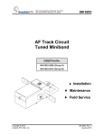
Operation, Installation and Maintenance
AFO-IIC
Audio Frequency Overlay System
Transmitter N451052-29XX
Receiver N451052-31XX
Track Coupling Unit N451052-190X
June 1985
© 1981, 1984, 1985, Union Switch & Signal Inc.
Printed in USA
An ANSALDO Signal Company
Revision Index
This service manual supersedes all previously issued manuals.. Please destroy all
outdated manuals.
SM6134 (06/85)
Revision
04/81
Revision
12/84
Revision
06/85
UNION SWITCH & SIGNAL
~
CONTENTS
Section
I
II
I
GENERAL INFORMATION
PURPOSE
1.1
DESCRIPTION
1.2
1. 2.1
General
1. 2. 2
Track Circuit Operation
Circuit Protection
1. 2. 3
1.3
AFO-IIC RECEIVER (N451052-31XX)
General
1. 3 .1
1. 3. 2
Input Filter Board (N451522-53XX)
1. 3. 3
Demodulator/Relay Driver Board
(N451522-68XX)
1.3.4
Specifications
1.4
RECEIVER RELAY
AFO-IIC TRANSMITTER (N451052-29XX)
1. 5
1. 5 .1
General
Transmitter Board (N451522-45XX)
1. 5. 2
Specifications
1. 5. 3
AUXILIARY EQUIPMENT
1. 6
Track Coupling Units (N451052-19XX)
1. 6 .1
1. 6. 2
Blocking Reactor
1-5
1-5
1-6
1-6
1-6
1-6
1-8
1-8
1-8
APPLICATION
2.1
FREQENCY SELECTION
General
2 .1.1
Compatibility with Motion Monitor
2 .1. 2
Compatibility With Coupling Units
2 .1. 3
Basic Application Rules
2 .1. 4
2.2
RECEIVER RELAY
TRACK COUPLING UNITS
2.3
2.4
BLOCKING REACTOR
General Applications
2.4.1
AFO and Microcode Compatibility
2.4.2
TRACK LEADS AND POWER SUPPLY
2.5
LIGHTNING PROTECTION
2.6
General
2.6.1
Track Terminal Protection
2.6.2
Battery Line Protection
2.6.3
SURGE-RIPPLE FILTERS
2.7
2-1
2-1
2-1
2-1
2-3
2-3
2-4
2-4
2-4
2-4
2-4A
2-6
2-9
2-9
2-9
2-9
2-11/12
1-1
1-1
1-1
1-1
1-1
1-3
1-3
1....:3
1-3
1-5
III INSTALLATION AND ADJUSTMENTS
3.1
WIRING CONNECTIONS
3.1.1
AFO-IIC Transmitter
3.1.2
AFO-IIC Receiver
3.1.3
Track Coupling Units
3.1.4
Blocking Reactor
3.2
EQUIPMENT ADJUSTMENTS
3-1
3-1
3-1
3-1
3-1
3-5
3-5
IV
4-1
4-1
4-1
4-1
4-2
4-2
4-2
FIELD MAINTENANCE
GENERAL
4.1
REQUIRED TEST EQUIPMENT
4.2
INSPECTION AND INITIAL CHECKS
4.3
MAINTENANCE PROCEDURES
4.4
Equipment Substitution Method
4.4.1
Voltage Measurement Method
4.4.2
i
(Rev. 6/85)
m
UNION SWITCH & SIGNAL
CONTENTS (Cont'd)
Section
v
I
SHOP MAINTENANCE
5.1
GENERAL
5.2
TRANSMITTER UNIT N451052-29X-X
Detailed Circuit Description
5.2.1
5.2.2
Required Test Equipment
5.2.3
Test Set-Up
5.2.4
Procedure Comments
Procedure Steps
5.2.5
5.2.6
Procedure Follow-Up
5.3
RECEIVER UNIT N451052-31XX TEST PROCEDURES
5.3.1
Detailed Circuit Descriptions
Required Test Equipment
5.3.2
Test Set-Ups
5.3.3
Procedure Comments
5.3.4
5.3.5
Procedure Steps
5.3.6
Procedure Follow-Up
5.4
TRACK COUPLING UNIT
Required Test Equipment
5.4.1
5.4.2
Test Set-Up
Test Procedure Comments
5.4.3
Test Procedure
5.4.4
Procedure Follow-Up
5.4.5
5.5
BLOCKING REACTOR
APPENDIX A
A. l
A.1.1
A. l. 2
A. 2
A.3
A.3.1
A.3.2
A.3.3
A.3.4
A.3.5
A. 4
A.5
A.5.1
A.5.2
A. 6
A. 7
A. 7 .1
A.7.2
5-1
5-1
5-1
5-1
5-2
5-2
5-2
5-9
5-10
5-10
5-10
5-13
5-14
5-15
5-21
5-22
5-23
5-23
5-23
5-23
5-24
5-25/26
5-25/26
Parts List
UNIT PART NUMBERS
Frequency-Classed Units
Miscellaneous Units
AFO-IIC RECEIVER BASIC ASSEMBLY
RECEIVER PRINTED CIRCUIT BOARDS
Standard Vs. Frequency-Determining Components
Input Filter PCB N451522-5302 to -5321,
Standard Components
Input Filter PCB N451522-5302 to -5321,
Frequency-Determining Components
Demodulator/Relay Driver PCB N451522-6802
to -6808, Standard Components
Demodulator/Relay Driver PCB N451522-6802 to
-6808, Frequency-Determining Components
AFO-IIC TRANSMITTER BASIC ASSEMBLY
TRANSMITTER PRINTED CIRCUIT BOARD
Transmitter PCB N451522-4502 to -4521,
Standard Components
Transmitter PCB N451522-4502 to -4521,
Frequency-Determining Components
TRACK COUPLING UNIT BASIC ASSEMBLY
TRACK COUPLING UNIT COMPONENT BOARD
N451053-580X
Standard Components
Frequency-Determining Components
ii
A-1
A-1
A-1
A-2
A-4
A-4
A-4
A-6
A-8
A-8
A-10
A-12
A-12
A-14
A-16
A-18
A-18
A-18
(Rev. 6/85)
UNION SWITCH & SIGNAL
OJ
ILLUSTRATIONS
.-c;:;,'\
!
Figure
Page
1-1
Typical AFO-IIC Track Circuit Operation
1-2
1-2
Typical AFO-IIC Highway Crossing Layout With
Overlapping Track Circuits
1-2
1-3
AFO-IIC Receiver Block Diagram
1-4
1-4
AFO-IIC Transmitter Block Diagram
1-7
2-1
Maximum Block Length
2-5
2-2
Requirements for Blocking Reactor
2-7
2-3
Applications of Reactor to AFO-IIC Track
Circuits
2-8
2-4
Track Lead Lightning Protection:
and Receiver
Transmitter
2-10
2-5
Track Lead Lightning Protection:
Units and Connections
Coupling
2-10
2-6
Power Supply Lightning Protection
2-10
3-1
Typical Wire Connections for Transmitter and
Receiver
3-2
3-2
Track Coupling Unit Internal Wiring
Connections, Groups 1 and 2 (N451052-1901
and -1902)
3-3
3-3
Track Coupling Unit Internal Wiring
Connections, Groups 3 and 4 (N451052-1903
and -1904)
3-4
5-1
AFO-IIC Transmitter Unit Schematic Diagram
5-3/4
5-2
Transmitter Test Set-Up
5-5
5-3
Physical Locations of Transmitter Test Points
5-6
5-4
Schematic Locations of Transmitter Test Points
5-7
5-5
Transmitter Test Oscillograms
5-8
5-6
AFO-IIC Receiver Unit Schematic Diagram
5-11/12
5-7
Receiver Test Set-Up using Matched Transmitter and Receiver
5-14
iii
ffi
UNION SWITCH & SIGNAL
ILLUSTRATIONS (Cont'd)
Figure
I 5-8
Page
Receiver Test Set-Up Using Function Generator and Audio Amplifier
5-16
5-9
Physical Locations of Receiver Test Points
5-17
5-10
Schematic Locations of Receiver Test Points
5-18
5-11
Receiver Test Oscillograms
5-19/20
5-12
Track Coupling Unit Test Set-Up
5-24
A-1
AFO-IIC Receiver Basic Assembly and Chassis
Wiring
A-3
A-2
Input Filter PCB Component Layout
A-5
A-3
Demodulator/Input Driver ~CB Component Layout
A-9
A-4
AFO-IIC Transmitter Basic Assembly and
Chassis Wiring
A-11
A-5
Transmitter PCB Component Layout
A-13
A-6
Track Coupling Unit Basic Main Assembly and
Chassis Wiring
A-17
A-7
Track Coupling Unit Component Board Assembly
A-19
TABLES
Page
Table No.
2-1
Basic Audio Frequency Ranges
2-2
3-2
Selected Compatible Frequencies of AFO-II
and Motion Monitor Equipment
2-2
3-1
Coupling Unit Internal Terminal Board
Connections
3-2
iv
(Rev. 6/85)
·1
UNION SWITCH & SIGNAL
w
SECTION I
GENERAL INFORMATION
1.1
PURPOSE
This manual describes the principles of Audio Frequency Overlay
(AFO-IIC) track circuits and provides application information for
the AFO-IIC equipment. This information is essential for planning
AFO-IIC installations. It includes track circuit·data necessary for
laying out track circuits and frequency allocation rules which are
necessary to provide optimum efficiency of operation.
1.2
1.2.1
DESCRIPTION
General
The AFO-IIC is designed to provide train detection in territories
without insulated rail joints, so long as certain warnings and
application rules are observed. These are described in Sections I
and II of this manual. AFO-IIC can be used for highway crossing
application or for continuous train detection in signal systems.
The AFO-IIC Transmitter signal is amplitudemodulated to provide immunity to noise in the rails. All AFO-IIC
Transmitters and Receivers are fully transistorized and operate from
a de power supply ranging from 9.5 to 16.2 volts. The term "audio
frequency" refers to the frequencies within the audio range
(20-20,000 Hz). The term "overlay" refers to the AFO signal
superimposed or overlaid on the existing track circuit.
All circuitry in the transmitter and receiver units is mounted on
printed circuit boards. The boards are hard-wired to external
terminals and enclosed in sheet steel housings designed for shelf,
wall or rack mounting. AAR terminal strips are provided for
external circuit connections.
1.2.2
Track Circuit Operation
The AFO track circuit detects the presence of a train through loss
of the audio frequency signal, which is shunted by the train axles.
This is shown in Figure 1-1. The track circuit is composed of a
transmitter, receiver and receiver relay. The transmitter
introduces an audio signal of a specific assigned frequency into the
track through two wires connected directly to the rails. This point
defines one end of the AFO track circuit. The receiver only
responds to a specific assigned frequency. It is also connected to
the rails with two wires; this point defines the other end of the
AFO track circuit. Upon receiving the proper frequency, the
receiver detects, amplifies, and rectifies the signal to provide an
output to operate an external relay. The contacts of the relay are
then employed in the same fashion as conventional track relay
contacts. The transmitter and receiver require a de power source
for operation. ·
6°134, p. 1-1
EB
UNION SWITCH & SIGNAL
UNOCCUPIED TRACK CIRCUIT
OCCUPIED TRACK CIRCUIT
RECEIVER
DC POWER
SOURCE
~'" ...........,~
:
:
,,,uununum,:
DC POWER
SOURCE
RELAY
RELAY
c
CONTROLLED
CIRCUITS
~,
I
~CONTROLLED
CIRCUITS
n
.)HIUtttttlllfttH,..,
°'i ..................~
ENERGIZED
Figure 1-1.
AFO SIGNAL
DEENERGIZED
SHUNTED
Typical AFO-IIC Track Circuit Operation
2 TRACK SIGNAL
1 TRACK SIGNAL
•
TRANSMITTER #2 FREQUENCY
TRANSMITTER #1 FREQUENCY
•
J L
1 TRACK
AFO-IIC
TRANSMITTER
#1
Figure 1-2.
6134, p. 1-2
c,
z
AFO-IIC
RECEIVER
00
en
0
er
#2
0
TRACK
RELAY
#2
c,
><(
3
:c
:i:
AFO-IIC
RECEIVER
#1
AFO-IIC
TRANSMITTER
#2
TRACK
RELAY
#1
Typical AFO-IIC Highway Crossing Layout With Overlapping
Track Circuits
UNION SWITCH & SIGNAL
A series of AFO-IIC track circuits can be superimposed on a track
section (see Figure 2-3). Each track circuit is designed to operate
independently without interference from other AFO-IIC or de track
circuits. This is most important where adjacent highway crossings
have overlapping approach limits. Also, it allows an overlap at the
crossing for an island circuit, as shown in Figure 1-2.
1.2.3
Circuit Protection
Surge protection is provided within the receiver and transmitter for
both the de line and track lead inputs. Refer to Section 2.6 for
lightning protection requirements.
Reverse polarity protection is also included. If battery polarity
is accidentally reversed, a protective fuse will blow which
disconnects the unit from the battery supply. This is intended to
prevent power loss to other equipment.
1.3
AFO-IIC RECEIVER (N451052-31XX)
1.3.1
General
The AFO-IIC Receiver operates over a de battery voltage range of 9.5
to 16.2 volts. In case of battery failure, the receiver is designed
to not be damaged from the battery charger rectifier or cause the
receiver relay to be falsely energized. A sensitivity adjustment is
built into the receiver unit to obtain the proper shunting
characteristics for each track circuit. The AFO-IIC Receiver is
housed with all circuit components mounted on two printed circuit
boards:
Input Filter and Demodulator-Relay Driver. Both boards are
mounted on the top plate, by means of a support bracket, and
enclosed within the housing. The design of the AFO-IIC Receiver
provides increased immunity from potential traction control choppers
and traction power supply interference in electrical railroads. The
receiver design also provides increased immunity from radio
interference.
I
1.3.2
Input Filter Board (N451522-53XX)
(See Figure 1-3)
The signal from the track is applied to a high selectivity band-pass
filter on the Input Filter board.
Its input is a low impedance,
series-tuned circuit which rejects de or low frequency ac voltages
present from any existing track circuit. The filtered AFO signal is
then applied to a gain adjustment circuit which includes a
"sensitivity" potentiometer. The gain is adjusted at installation
to establish the track circuit shunting sensitivity. The signal is
then applied to a tuned step-up transformer, then demodulated by the
envelope detector. Its output is then fed into the impedance
matching circuit to provide a low impedance source to the modulation
band-pass filter on the next board.
(Rev. 6/85)
6134, p. 1-3
m
UNION SWITCH & SIGNAL
AFO-IIC
TRANSMITIER
,r
-
-
-
- -
- - --
- - -
AFO RECEIVER
-
-
-
-
-
-
-
-
-
l
I
HIGH SEL.
BANDPASS
FILTER
-
-
GAIN
ADJUSTMENT
TUNED
STEP-UP
TRANSFORMER
~
I
II
~
.
SENSITIVITY
IMPEDANCE
MATCHING
STAGE
.....-
I
I
--
ENVELOPE
DETECTOR
I
I
+DC
- -- -- - - - -- - - -- -- --
r
MODULATION
FREQUENCY ,--+
BANDPASS
FILTER
DC MAKER
&
OSCILLATOR
--.
INPUT Fl LTER
BOAR D
-DC
-- -- -- -- - - ---
--
AMPLIFIER
RECTIFIER
&
NEG-DC MAKER
--
+DC
-DC
--
..,__
--- -
-
-
-
--
-
- -
-
'
-
-
-
- - - -
,--.. I+
400-soo n
_J
--- -
AFO
TRACK RELAY
(TYPICAL: US&S PN-150B, PN150BH, DN-22BH, DN-11B)
Figure 1-3.
6134, p. 1-4
-,
REVERSE
BATIERY &
SURGE
PROTECTION
_J
DEMODULATOR/RELAY
DRIVER BOARD
I
AFO-IIC Receiver Block Diagram
+BATIERY
---BATIERY
UNION SWITCH & SIGNAL
1.3.3
Demodulator/Relay Driver Board (N451522-68XX)
m
(See Figure 2-3)
At the Demodulator/Relay Driver board, the recovered envelope of the
signal is filtered to pass only the assigned modulation frequency.
A negative de voltage is developed from the rectified output to
power a high frequency oscillator which acts as a level detector.
The output of the oscillator is amplified and again rectified to
develop a negative de voltage to drive the relay.
Also included on the Demodulator/Relay Driver board is power surge
protection circuitry at the battery connection to protect the solid
state electronics against voltage spikes. Reversed battery
protection is also included.
1.3.4
I
1.4
Specifications
Input Voltage:
9.5 - 16.2 Vdc
Input Current:
0.07 amp. at 12 Vdc
Output Voltage:
(400 ohm load)
5.05 Vdc minimum (with 3 mV RMS
input signal and 9.5 volts battery)
Signal Sensitivity:
3.0 + 0.3 millivolts RMS minimum
detectable signal (14.1 + 2.0
millivolts P-P during the period of
the modulation cycle when the signal
is at a maximum)
Input Impedance (Track):
1.25 ohm at center of assigned
frequency (nominal)
Output Load:
400 or 500 ohm Relay
Bandwidth:
-3 db at +4.0% of assigned frequency
Operating Frequencies:
Refer to Table 3-1
Temperature Range:
-4ooc to +11°c (-40°F to
+160°F)
Surge Protection:
Built-in
Dielectric Breakdown Test
3000 Vdc rms at 60 Hz between track
leads and input (battery) leads.
RECEIVER RELAY
A 400 or 500 ohm, biased de relay is typically used as a receiver
relay for the AFO-IIC system. Refer to section 2.2 for recommended
relays and application data.
(Rev. 6/85)
6134, p. 1-5
m
UNION SWITCH & SIGNAL
1.5
AFO-IIC TRANSMITTER (N451052-29XX)
1.5.1
General
The AFO-IIC Transmitter has a fixed output. It operates on a de
battery voltage range of 9.5 to 16.2 volts. The modulated signal is
designed to provide noise immunity for the circuit and reduce
battery consumption by the transmitter. The AFO-IIC Transmitter
contains one printed circuit board: Transmitter.·
1.5.2
Transmitter Board (N451522-45XX)
(See Figure 1-4)
The Transmitter board accomplishes four functions, including
generation of the basic carrier frequency, generation of the
modulation rate frequency, summing of the carrier and modulation
signals and voltage amplification.
The fundamental carrier signal is generated at the carrier.
oscillator and is ·coupled to a summing circuit. A modulation
oscillator generates the modulating signal. It is coupled to the
summing circuit where it causes the carrier signal to increase and
decrease in amplitude at the modulation rate. The signal, after
being coupled through a buffer stage, is of very low energy level
and requires several stages of current and voltage amplification.
The final stage of amplification transforms the high impedance
output of the emitter follower and provides low impedance coupling
to the track through a two transistor push-pull power amplifier.
The amplifier has at its output a series resonant circuit. The
series-resonant circuit allows easy passage of the modulated carrier
frequency signal and inhibits passage of any unwanted signals, such
as harmonics.
1.5.3
Specifications
Input Voltage:
9.5 - 16.2 Vdc
Input Current:
(2 ohm output load)
0.40 +.06 amp. at 12 V input
Output Voltage:
(2 Ohm(load, 12.0V battery)
5.0 + 0.4 VP-P during "ON" period
of modulation.
Output Impedance:
(Norn. at center of
assigned frequency)
1 Ohm
Operating Frequencies:
Refer to Table 3-1
Tempe~ature Range:
-4o 0 c to +11oc (-4ooF to
+160°F)
Surge Protection:
Built-in
Min. Ballast Resistance:
3 ohm/1000 Ft.
6134 I P• 1-6
UNION SWITCH & SiGNAL
b:::I ,
AFO
RECEIVER
f
-
r
------,
I
OUTPUT
TRANSFORMER
WITH
RESONANT
OUTPUT CIRCUIT
J•
EMITTER
FOLLOWER
AMPLIFIER
DRIVER
TRANSFORMER
EMITTER
FOLLOWER
AMPLIFIER
BUFFER STAGE
WITH
CURRENT GAIN
CARRIER
OSCILLATOR
SUMMING
CIRCUIT
WITH TUNED OUTPUT
MODULATION
RATE
OSCILLATOR
TRANSMITTER BOARD
----------------~
Figure 1-4.
AFO-IIC Transmitter Block Diagram
6134, p. 1-7
b'j·
UNION SWITCH & SIGNAL
1.6
AUXILIARY EQUIPMENT
1.6.1
Track Coupling Units (N451052-19XX)
A Track Coupling unit is used when the AFO signal must be passed
around insulated joints and the existing track circuit energy must
be blocked. This unit uses transformer-coupling to pass the AFO
signal to the next track section. Redundant blocking of de passage
is accomplished by both the transformer and series components to
provide vitality of the system. When insulated joints need to be
traversed, the frequency of an AFO-IIC transmitter-receiver pair on
either side of the joint must be the same as the coupling unit.
Four coupling units are available. Each is capable of passing several different distinct frequencies {three units pass six frequencies,
one passes four frequencies; see Figure 3-2). The units have tuned
taps for each frequency in its group. Thus, a different unit is required for each frequency to be passed around the insulated joints.
The frequency-determining taps are located inside the unit and must
be connected to the proper taps as determined by the selected operating frequency. The Track Coupling Unit has the same housing and
mounting options as the AFO-IIC receiver and transmitter. Table 3-1
contains general part number references for the Track Coupling Units.
1.6.2
Blocking Reactor
The Blocking Reactor blocks the AFO signal while passing de and low
frequency ac. Reactor N451036-0302 is recommended for this
application. It has a de resistance of 0.01 ohm and a current
rating of 7 amperes. This reactor may be mounted on a relay rack in
a PN-250 space or on a wall or shelf. Dimensions are 8" x 5"
mounting plate with a depth of 3-5/8". Refer to section 2.4 for
various applications to AFO-IIC track circuits.
WARNING
AFO EQUIPMENT IS DESIGNED TO OPERATE OVER A NORMALLY EXPECTED VARIETY OF ENVIRONMENTAL CONDITIONS.
HOWEVER ELECTRIC PROPULSION EQUIPMENT EMPLOYING
PHASE CONTROL OR CHOPPER CONTROL MAY CREATE AN EXCESSIVE AMOUNT OF ELECTROMAGNETIC INTERFERENCE IN
THE AUDIO SPECTRUM, THUS CAUSING IMPROPER AND POTENTIALLY UNSAFE OPERATION OF THE AFO RECEIVERS.
SIMILARLY, THE OPERATION OF HAND-HELD RADIO TRANSMITTERS IN THE VICINITY OF OPEN WAYSIDE HOUSINGS
MAY CAUSE SUFFICIENT RADIO INTERFERENCE TO RESULT
IN POTENTIALLY UNSAFE OPERATION OF AFO AND OTHER
ELECTRONIC DETECTION EQUIPMENT.
Proper application of AFO equipment under the conditions described
above requires special engineering analysis. Contact the US&S
District Sales representative to discuss possible audio frequency
interference of the AFO equiupment in the customer's application.
6134, p. 1-8
UNION SWITCH & SIGNAL
{lJ
SECTION II
APPLICATION
2.1
FREQENCY SELECTION
2.1.1
General
The AFO-IIC System provides transmitter and receiver units with all
frequencies between 800 and 5000 Hz. The frequency spectrum is
divided into 20 groups, as shown in Table 2-1. The desired
frequencies of the transmitter and receiver units are selected in
accordance with unit part numbers. Refer to section A.1.1 for these
part numbers.
WARNING
THERE MUST BE At LEAST A 25% SEPARATION BETWEEN THE
ASSIGNED FREQUENCIES OF ANY EQUIPMENT CONNECTED TO
THE TRACK, WITHIN A COMMON BLOCK, BETWEEN INSULATED
JOINTS. IN A TWO-TRACK SYSTEM, THE FREQUENCY SEPARATION OF TRACK 1 AND TRACK 2 UNITS MUST NOT BE LESS
THAN 5%. OTHERWISE, A HAZARD MAY BE CREATED THAT
COULD LEAD TO UNSAFE OPERATION.
Ideally, frequency selection of AFO-IIC units should be staggered.
When designing an AFO-IIC system, observe the following rules:
1.
Obtain optimum separation from the sum and difference
frequencies of assigned AFO-IIC frequencies.
2.
Avoid harmonics up to the fifth harmonic of AFO-IIC frequencies.
3.
Minimize harmonic mixing and the mixing of harmonics with the
assigned AFO-IIC frequencies.
4.
Obtain optimum separation from the 60 cycle power frequency and
its harmonics and the mixing of these with AFO-IIC frequencies.
2.1.2
Compatibility with Motion Monitor
Table 2-2 shows the frequency compatibility between some preselected AFO-IIC and Motion Monitor frequencies. Other AFO-IIC
frequency allocations must follow these rules:
1.
Avoid AFO frequencies which are a harmonic of the Motion Monitor
frequency, up to the seventh harmonic.
2.
Obtain optimum separation from the 60 cycle power frequency and
its harmonics, and the mixing of these with Motion Monitor
frequencies·and its harmonics.
6134, p. 2-1
t:::tJ
UNION SWITCH & SIGNAL
Table 2-1.
Frequency
Range
Designation
FR
FR
FR
FR
FR
FR
FR
FR
FR
FR
FR
FR
FR
FR
FR
FR
FR
FR
FR
FR
Basic Audio Frequency Ranges
AFO-IIC
Coupling Unit
Frequency
1
2
3
4
5
6
7
8
9
10
11
12
13
14
15
16
17
18
19
20
870, 885, 930, 945
980, 1050
1120
1180, 1215
1285, 1330
1420, 1520
1660
1860, 1945
2140
2365
2540
2720
3360, 3410
Table 3-2.
Modulation
Rate
800-875
876-960 ·
961-1055
1056-1155
1156-1265
1266-1385
1386-1520
1521-1665
1666-1825
1826-2000
2001-2190
2191-2400
2401-2630
2631-2885
2886-3160
3161-3465
3466-3800
3801-4165
4166-4560
4561-5000
18
18
22
22
22
27
27
27
39
39
39
49
49
49
68
68
68
94
94
94
Selected Compatible Frequencies of AFO-II and Motion
Monitor Equipment
AFO-II Frequency
930
1050
885
1330
1050
1120
2140
930
6134 I P• 2-2
Frequency
Range
and
and
and
and
and
and
and
and
3410
3360
1860
3360
2540
2720
1420
3410
Hz
Hz
Hz
Hz
Hz
Hz
Hz
Hz
Motion Monitor Frequency
207
230
390
390
390
405
405
405
Hz
Hz
and
and
and
and
and
and
570
570
570
630
630
630
Hz
Hz
Hz
Hz
Hz
Hz
UNION SWITCH & SIGNAL
2.1.3
t:i::J
Compatibility With Coupling Units
Compatible AFO-IIC and Track Coupling Unit frequencies are shown in
Table 2-1. Frequencies not compatible with the AFO-IIC Track
Coupling Units must be applied in a track section where it is not
necessary to bypass an insulated joint.
2.1.4
Basic Application Rules
Certain basic rules must be followed in the application of AFO-IIC
track circuit equipment to ensure maximum effectiveness and
security. These are as follows:
1.
Do not repeat the same frequency on the same track unless the
track circuits are separated by two pairs of insulated joints.
a.
If a coupling unit is used to bypass a set of insulated
joints, these joints may not be counted in applying
Rule 1 above.
b.
Frequency separation between adjacent AFO-IIC pairs
in the same block must be at least 25% apart.
2.
The same AFO-IIC frequency must not be located adjacent on
parallel tracks.
3.
When more than one highway crossing is involved in an AFO
layout, a ripple-free power supply must be provided for the
transmitters.
Surge-Ripple Filter N451036-0702 is available for insertion between
the transmitter and the power supply (refer to section 2.7).
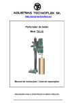
In selecting and applying the frequencies, the required length of
the track circuit must also be considered since the AFO signal
attenuation in the track circuit is directly proportional to the
frequency. Figure 2-1, a block length versus frequency curve, shows
the maximum effective block length permitted for the AFO-IIC
equipment.
NOTE
For each coupling unit used in an AFO-IIC track circuit, the effective length of that track circuit is
reduced by 500 feet.
6134, p. 2-3
UNION SWITCH & SIGNAL
Figure 2-1 represents the maximum lengths for adjusting the track
circuit at 3, 5 and 20 ohms ballast resistance and does not consider
the increase in receding ringing distance resulting from a drop in
ballast resistance.
2.2
RECEIVER RELAY
The AFO-IIC receiver incorporates an electroniq level detector which
is designed to simplify relay requirements. US&S relays DN-22BH or
the PN-150BH are recommended for the AFO-IIC receiver relay. However,
other 400 to 500 ohm relays such as the US&S PN-150B (N322500-701) or
the DN-llB (N274069) can be used with the AFO-II equipment.
2.3
TRACK COUPLING UNITS
Three Track Coupling Units are provided to pass any one of the six
frequencies in the group for which either is tuned and connected,
(refer to Table 2-1). A fourth Track Coupling Unit is capable of
passing four frequencies. All other frequencies are rejected. Refer
to section 6.X for part number and frequency cross-references. See
Figures 3-2 and 3-3 for coupling unit wiring connections.
NOTE
Since each Track Coupling Unit has tuned internal taps
for each frequency in its class, one unit is required·
for each frequency passed around the insulated joint pair.
Each time an AFO-IIC signal is coupled around insulated joints, the
effective length of the AFO track circuit is reduced by an average of
200 to 300 feet, depending on the location of the unit within the
track circuit.
Due to severe restriction of effective track circuit lengths,
coupling units cannot be used to bypass insulated joints in the
higher frequencies.
2.4
2.4.1
I
BLOCKING REACTOR
General Application
Blocking Reactors are used to block the AFO signal while passing de
and low frequency ac. For example: to prevent shunting the AFO
signal through the battery, a Blocking Reactor must be installed in
series with one lead of an existing de battery rail connection which
occurs near an AFO-IIC track circuit. The purpose of the reactor is
to block the AFO signal while passing de and low frequency ac. See
View "A" of Figure 2-3. This is not necessary if an AFO-IIC track
circuit occurs near the relay end of an existing de track circuit.
The coils in the relay will provide the necessary impedance to block
the AFO signal. See Figure 2-3 for other applications.
6134, p. 2-4
(Rev. 6/85)
/~
UNION SWITCH & SIGNAL
2.4.2
AFO and Microcode Compatibility
In applications where Microcode is overlayed on AFO-IIC track
circuits, a blocking reactor may be required to prevenet shunting
the AFO signal. When the Microcode is confined within the AFO track
circuit, blocking reactor No. 1 listed below is recommended.
Where the Microcode in a particular application is operating near
the upper limit of its distance range (see Microcode application
service manual No. 6195), blocking reactor No • .2 listed below is
recommended. The blocking reactor is installed in series with one
of Microcodes track leads.
The determination when to use blocking reactors in Microcode
applications outside the confinement of the AFO track circuit is
decided by the following steps:
1.
By knowing the frequency of the adjoining AFO-IIC unit.
2.
And by calculating the critical distance "D" (Diagram A) beyond
which no reactor is required at a particular AFO frequency using
the formula below:
=
D
1300
v
(in feet)
f
Where f
=
KHz
AFO-IIC frequency is 0.885 KHz
Example:
Thus Distance D
=
.!lQQ
v:aas
= 1382
feet
This means that when a microcode is located within 1382 feet from
either a AFO-IIC transmitter or receiver (885 Hz) it is required
to have a reactor in series with one of its track leads.
Here again the selection of the No. 1 reactor is recommended.
However if as described above, the block length of the Microcode
is near its upper limit of its advertised distance range the use
of No. 2 blocking reactor will suffice.
In fact~ if the
Microcode distant requirement is really critical, two No. 2
blocking reactors may be paralleled when microcode is located at
least
"D"
feet from the adjacent AFO unit.
-2-
I~
AREA WHERE BLOCKING REACTOR IS REQUIRED
I
"D"
I
I
-
I!~
·1
I
MICROCODE
I I
I
AFO-TX
,...
"D"
!1
-
l
I
I
AFO-RX
I
Diagram a - Microcode Application
(Rev. 6/85)
6134, p. 2-4A
ffi
UNION SWITCH & SIGNAL
Blocking Reactor No. 1
N451036-0302, inductance of 1.9 mh and has a DC resistance of
0.01 ohm.
Blocking Reactor No. 2
N451036-1701, inductance of 1.0 mh and has a DC resistance of
0.01 ohm.
6134, p. 2-4B
(Rev. 6/85)
UNION SWITCH & SIGNAL
m
6000
MAXIMUM T. C. LENGTH TO OBTAIN
3 MV AT THE RECEIVER WITH .06 OHM
SHUNT AND VARIOUS BALLAST CONDITIONS IN OHMS PER 1000 FT.
5000
~
w
:C
z
>u
zw
4000
::>
0
w
a:
u.
e:>
z
3000
~a:
w
0
0..
2000
1000
1
2
3
4
5
6
7
8
TRACK CIRCUIT LENGTH IN THOUSAND FEET
Figure 2-1.
Maximum Block Length
6134, p. 2-5
m
UNION SWITCH & SIGNAL
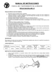
The need for the reactor depends upon the impedance presented by the
existing de equipment, their leads, their distance from the AFO-IIC
track circuit, and the AFO-IIC frequency employed. One reactor is
effective for all AFO frequencies. Figure 2-2 shows the
relationship between minimum impedance, AFO-IIC frequency, and
distance. For example, if the AFO frequency is 1330 Hz and the
distance is 200 feet, a reactor must be installed if the impedance
in path A, B, C and Dis less than 0.7 ohm.
Blocking Reactors may also be used for applications as shown in
Views "B" to "D", Figure 2-3.
View "B" - Allows the de track circuit to be shunted by a switch
circuit controller without shunting the AFO signal.
View "C" - Defines the AFO track circuit at a specific point with
insulated joints and allows the de circuit .to pass.
View "D" - Keeps the AFO signal out of the fouling circuit at a
turnout.
2.5
TRACK LEADS AND POWER SUPPLY
Leads from the AFO-IIC units to the track should be arranged to
minimize their series inductance. Unsheathed single wires may be
used in pairs, provided that they are twisted, (3 twists per foot)
or kept together within the same conduit. Metal-sheathed single
wires should not be used. Sheathed wire or conduit is not required
for AFO-IIC wiring within the wayside housing. A Transmitter and
Receiver Unit of the same frequency should have its own leads to the
track.
The battery charger rectifier leads should be wired directly to the
battery and then to the power busses or equipment to prevent the
battery from being removed from the circuit due to a broken wire,
and to ensure a ripple-free power supply.
A resistor should never be placed in the power lead to a transmitter
or receiver, since the total power lead resistance must be less than
0.15 ohm for transmitters and 0.5 ohm for receivers. If either of
these values is exceeded, or if a signal (or ripple) greater than
0.5 volt peak-to-peak exists on the power leads, a surge-ripple
filter must be employed.
The following total lead wire resistances are the maximum
permissible for maximum track circuit length and minimum "receding
ringing" distance:
1.
2.
3.
4.
5.
6.
Transmitter to Rails
Receiver to Rails
Receiver to Relay
Battery to Receiver
Battery to Transmitter
Coupling Unit to Rails (Each End)
6134, p. 2-6
.15 ohm
0.15 ohm
25.00 ohms
0.5 ohm
0.15 ohm
0.15 ohm
UNION SWITCH & SIGNAL
ttJ
MINUMUM REQUIRED IMPEDANCE IN OHMS
OF CIRCUIT A-8-C-D
TO APPROXIMATE EXISTING IMPEDANCE,
ADD RESISTANCE OF A-B- AND C-D.
l....•--d--·---1
A
AFO-+-
TRACK
---1----1
D
c
TRANSMITTER
OR RECEIVER
TRACK
BATTERY
w
u
z
~
l.Ot---11Ht-~rT-t--'r't--"ll""t-""""'-.-t----,~--+---+-~-+~
~
~
f1
f2
=
=
=
=
=
=
=
=
=
885 Hz
930 Hz
f3
10!l) Hz
f4
1120 Hz
fS
1330 Hz
f6
1420 Hz
f7
1860 Hz
f8
21-40 Hz
f9
2540 Hz
= 2120 Hz
fl1 = 3360 Hz
fl2 = 3410 Hz
f13 = 4565 Hz
fl 4 = !l:>90 Hz
no
0
600
DISTANCE "d" IN FEET
Figure 2-2.
Requirements for Blocking Reactor
6134, p. 2-7
m
UNION SWITCH & SIGNAL
TRACK
AFO AND DC 1~
I
1
: REACTOR
AFO-IIC
I
----1:
2 ~
DC BATTERY
VIEW "A"
TRANSMITTER
OR
RECEIVER
AFOAND D C -
TRACK
REACTOR
VIEW "B"
AFO
AND DC
DC
. ONLY
TRACK
OR
AFO AND
DC
DC
ONLY TRACK
.
1 1A-..::r~Tr::::.,.=¥=:'lrt:...62
REACTOR
~l:::¥¥~i......l.2
VIEW "C"
REACTOR
AFO
AND DC
AFO AND DC
· TRACK
DC ONLY
REACTOR
VIEW "D"
Figure 2-3.
6134, p. 2-8
Applications of Reactor to AFO-IIC Track Circuits
UNION SWITCH a SIGNAL
2.6
2.6.1
ti:j
LIGHTNING PROTECTION
General
In order to limit surge voltages from lightning, it is important to
use suitable arresters between any points of exposure. This is best
accomplished using a shunt arrester between the track leads to each
unit and series arresters from each track lead to a common ground
bus. The bus should be connected directly to the·housing signal
poles and all grounds at the location to limit the surge voltage
between any connections on the equipment or between the equipment
and the housing.
NOTE
Ground wires should be short and without sharp bends.
Each of the series arresters should limit the surge voltage across
itself to less than 1500 volts (peak) to prevent the voltage between
any two points from exceeding 3000 volts (peak).
2.6.2
Track Terminal Protection
Lightning damage can occur from surges entering the AFO-IIC units
either through the track terminals or through the battery
terminals. These terminals must be protected as follows:
The track terminals of each AFO-IIC Transmitter and Receiver should
be protected by both series and shunt lightning arresters as shown
in Figure 2-4 and the coupling unit as shown in Figure 2-5.
Reference 1 in these figures should be a US&S USGA Arrester with a
minimum breakdown rating of 500 peak volts and a maximum rating of
1300 peak volts.
Reference 2 should be a US&S USGA Arrester with a minimum breakdown
rating of 75 peak volts and a maximum rating of 200 peak volts.
Ground connections, reference 3, should be made to the common low
voltage ground bus system that includes grounds at cases or houses.
Make ground connections and jumpers with i6 AWG wire. Messenger
wire or metallic sheath of cable, if used, may serve as tie-in
between cases or houses.
2.6.3
Battery Line Protection
Although the AFO-IIC Transmitter and Receiver have built-in surge
suppression, they require additional protection across the power
supply. This is accomplished by using the USG Shunt Arrester,
reference 2 of Figure 2-6, across the power leads to the AFO-IIC
equipment.
6134, p. 2-9
m
UNION SWITCH & SIGNAL
TRACK
AFO-IIC
RECEIVER
AFO-IIC
TRANSMITTER
3
3
0
N451552-0302, USG-A ARRESTER (WITH TERM. BLOCK)
©
N451552-0101, USG-A ARRESTER
Figure 2-4.
-
@
TWIST PAIR
GROUNOBUS
Track Lead Lightning Protection:
Receiver
TO TRANSMITTER
Transmitter and
TO RECEIVER -
Q)
2
3
0
0
3
4
COUPLING UNIT
3
N451552-0302, USG-A ARRESTER (WITH TERM. BLOCK)
N451552-0101, USG-A ARRESTER
Figure 2-5.
©
GROUNDBUS
TWIST PAIR
Track Lead Lightning Protection:
Connections
Coupling Units and
DC POWER BUS
+
AFO-B
.t.
©
AFO-N }
TO AFO-IIC UNITS
N451552-0301 USG-A SHUNT ARRESTER (WITH TERM. BLOCK)
Figure 2-6.
6134, p. 2-10
::::0
Power Supply Lightning Protection
UNION SWITCH & SIGNAL
2.7
W
SURGE-RIPPLE FILTERS
Normal operation of AFO-IIC Transmitters and Receivers directly from
a rectifier is not recommended since reliability of filter
components will decrease due to excessive ripple. If the battery
supply has a ripple or an ac signal greater than 0.5V peak-to-peak,
a surge-ripple filter must be used. If more than one filter is
required because of current capacity, all transmitters should be
connected to one filter and all receivers to another filter.
A transmitter and receiver of the same frequency should not be
connected to the same surge-ripple filter, nor should they be
connected to the same battery unless a surge-ripple filter is
employed to isolate their power leads. This requirement is
satisfied by placing a surge-ripple filter in the power leads to
either unit, but preferably the receiver. When more than one
transmitter/receiver pair is powered from the same source,
connecting all the receivers to one filter (up to the filter's
current capacity) will satisfy the reqtiirement.
Refer to Table 6-1 for Surge-Ripple Filter part number.
6134, p. 2-11/12
UNION SWITCH & SIGNAL
~
SECTION III
INSTALLATION AND ADJUSTMENTS
NOTE
All AFO-IIC equipment must be installed in accordance
with approved application plans.
CAUTION
LEAVE DC POWER FOR ALL AFO-IIC EQUIPMENT DISCONNECTED
UNTIL INITIAL EQUIPMENT ADJUSTMENTS ARE COMPLETE,
(section 3.2), OTHERWISE EQUIPMENT DAMAGE MAY RESULT.
3.1
WIRING CONNECTIONS
3.1.1
AFO-IIC Transmitter (See Figure 3-1)
1.
Connect the positive and negative power supply to terminals #1
and i2, respectively. Make certain to observe correct polarity
(+de il, -de i2).
2.
Connect the track leads to terminals #3 and i4.
3.1.2
AFO-IIC Receiver (See Figure 3-1)
1.
Connect the positive and negative power supply to terminals il
and i2, respectively. Make certain to observe correct polarity
(+de il, -de #2).
2.
Connect the track leads to terminals #3 and #4.
3.
Connect the+ and - relay leads to receiver terminals #5 and i6,
respectively. Make certain to observe correct polarity.
3.1.3
Track Coupling Units (See Figures 2-5, 3-2 and 3-3)
The Track Coupling Unit selection, groups 1, 2, 3 and 4 (refer to
Table 3-1) is based on the class of the frequency for which it is
used. Total track lead resistance should be kept below 0.15 ohm per
pair. The coupling units should not be used within 100 feet of a
receiver or transmitter. One unit is required for each frequency to
be passed around the insulated joints.
Before connecting a coupling unit to the track, set the proper as·
frequency as follows:
1.
Remove the unit from the sheet metal cover and locate the four
wires on terminal strips (within the cover). The connections of
these wires are used to set up desired frequency. See Table 3-1
and Figures· 3-2 and 3-3.
6134, p. 3-1
m
UNION SWITCH & SIGNAL
TRACK
ARRESTERS
ARRESTERS
BATT.+
BATT.+
5
BATT.-
BATT.-
Figure 3-1.
+
6
4
TRACK
RELAY
RECEIVER
Typical Wire Connections for Transmitter and Receiver.
2.
Connect the black and brown wires to one of the assigned
frequencies as indicated on terminals one to eight.
3.
Connect the white and blue wires only when one of the first
three frequencies in each group located in Table 3-1 are
assigned. When not assigned, these wires should be connected to
the spare terminal 4.
4.
Reassemble the unit in its sheet metal cover.
Table 3-1.
Coupling Unit Internal Terminal Board Connections
Frequency
Connect Wire (Color) On Terminal
(Hz)
Group
Group
Group
Group
1
2
3
4
-----
------
885
1050
1330
1860
2540
3360
-------
930
1120
1420
2140
2720
3410
-------
6134, p. 3-2
--
--
870
980
1180
1285
1660
1945
--
945
--
1215
--
1520
2365
Black to
Term. #
1
2
3
6
7
8
1
2
3
6
7
8
Brown to
Term. #
1
2
3
6
7
8
1
2
3
6
7
8
White to
Term. #
1
2
3
4
4
4
1
2
3
4
4
4
Blue to
Term. #
1
2
3
4
4
4
1
2
3
4
4
4
UNION SWITCH & SIGNAL
BK.
TRACK INPUT
LEAD 1
L1
L2
870
870
w.
p
~
980
G.
C1
~
I sv.
Y.
1285
0.
W.I
1660
A.
1945
BR.
C2
8
TRACK OUTPUT
LEAD 1
3
C3
1180
3
R.
b'j
C4
OUTPUT
INPUT
w.
TRACK INPUT
LEAD2
TRACK OUTPUT
LEAD 2
4
CIRCUIT DIAGRAM FOR BOARD #3 N451053-5803
BK.
TRACK INPUT
LEAD 1
~
L1
L2
945
945
Y.
Y.
A.
.2
Cl
1215
3
SPARE
{·
o.
es
se
~
C2
8
TRACK OUTPUT
LEAD 1
3
o.•}
1215
6
•1
2·~
C3
SPARE
6
1520
A.
2365
BR.
1520
R.
2365
BR.
1•
!!:.;
C4
8
INPUT
OUTPUT
TRACK OUTPUT
LEAD 2
TRACK INPUT
LEAD 2
CIRCUIT DIAGRAM FOR BOARD #4 N451053-5804
Figure 3-2.
Track Coupling Unit Internal Wiring Connections
Groups 1 and 2 (N451052-1901 and -1902)
6134, p. 3-3
m
UNION SWITCH & SIGNAL
TRACK INPUT
LEAD 1
t---+--B_K_e--t
Ll
L2
885
885
~
BK. , _ _ _ _R_.---ti---t
TRACK OUTPUT
3
LEAD 1
C3
Cl
~
C2
INPUT
TRACK INPUT
LEAD 2
OUTPUT
2 l--+-0-·-------------'
w.
.._-------------t---t
4
TRACK OUTPUT
LEAD2
CIRCUIT DIAGRAM FOR BOARD #1 N451053-5801
Ll
930
L2
930
~
TRACK INPUT
LEAD 1
t--+-BK_._..,.-1
~
Cl
,su.
C2
______
R._ _ _-1
3
C3
TRACK OUTPUT
LEAD 1
..!,
C4
INPUT
OUTPUT
w.
.....------------t---t
TRACK INPUT
LEAD 2
4
TRACK OUTPUT
LEAD 2
CIRCUIT DIAGRAM FOR BOARD #2 N451053-5802
Figure 3-3.
6134, p. 3-4
Track Coupling Unit Internal Wiring Connections
Groups 3 and 4 (N451052-1903 and -1904)
UNION SWITCH & SIGNAL
tij-.
After making the proper internal connections, connect the unit to
the track as follows (see Figure 2-5):
1.
Connect track leads from terminals 1 and 2 to the rails on the
transmitter side of the insulated joints.
2.
Connect track leads from terminals 3 and 4 to the rails on the
receiver side of the insulated joints.
3.1.4
Blocking Reactor (See Figure 2-3)
Ase required by the application, connect the Blocking Reactor in
series with one side of a circuit or track lead using terminals 1
and 2.
3.2
EQUIPMENT ADJUSTMENTS
NOTE
Do not proceed with the following adjustments until all
wiring connections have been completed.
Initial adjustments must be made as follows:
1. · Using a voltmeter, check for correct output voltage on the de
supply that will be used at the transmitter and receiver
(nominal 12 volts).
2.
Connect de power to all AFO-IIC equipment; make ce.rtain to
observe proper polarity.
NOTE
The equipment will not be damaged if de power is applied
with the wrong polarity, but the protective fuses will
be blown and must be replaced before further operation.
3.
Connect a de voltmeter (minimum 10,000 ohms/volt sensitivity and
a 0-10 volt range) across the relay terminals.
4.
When power is applied, a de voltage of at least 5.5 volts should
be developed across the receiver relay terminals. If the
voltage is not at least 5.5 volts, loosen the lock nut on the
receiver's sensitivity adjustment and turn the shaft clockwise
until the voltage is as specified. Then lightly tighten the
lock nut.
NOTE
If at least 5.5 volts cannot be obtained, check all
connections on the transmitter, receiver, track coupling
units,·and reactors.
6134, p. 3-5
m
UNION SWITCH & SIGNAL
NOTE
The AFO-IIC receiver incorporates an electronic level
detector in the relay driver circuit. The hysteresis
of this circuit, when operated near its threshold, is
relatively narrow and therefore quite sensitive to environmental changes. From a maintenance standpoint,
it would be tedious to readjust the circuit every time
a small change has taken place in the intervening period. Therefore, it is recommended that the AFO-IIC
approach track circuit be initially adjusted for a
shunting sensitivity in excess of .06 ohms. Typically,
a value between .07 and .10 ohms is desirable.
5.
Connect a 0.08 ohm resistance shunt across the rails at the
receiver track connections. Use rail clamps to insure a good
contact.
NOTES
In no case should the AFO-IIC Receiver be adjusted for a
shunt of less than 0.06 ohm resistance. If a higher
Resistance shunt is used, the overlap distance will be
increased proportionately.
The following adjustment should be made when the ballast
is in good condition (20 ohms or higher per one thousand
feet). This should avoid any appreciable decrease in
shunting sensitivity with any further improvement in
ballast. Also, all batteries must be fully charged and
all track equipment connected when the adjustment is made.
6.
Loosen the receiver sensitivity adjustment lock nut and adjust
the receiver sensitivity so that the relay just drops out with
the shunt in place. Observe and record the voltmeter reading.
7.
Tighten the sensitivity adjustment lock nut and check the
voltmeter to see that such tightening has not changed the
voltmeter reading. If necessary, loosen the nut, readjust the
sensitivity and tighten the nut again.
8.
Remove the track shunt.
9.
Observe and record the voltmeter reading.
The relay should then pick up.
10. Check that the circuit shunts with a 0.06 ohm shunt at the
transmitter end of the circuit.
NOTES
If a ttansmitter or receiver is ever removed or replaced in service, the circuit must be readjusted
according to the above procedure.
6134, p. 3-6
UNION SWITCH & SIGNAL
tl1
Multiple receivers are frequently used to provide
several track circuits with one transmitter. The
shunting of each receiver must be adjusted individually. Adjustment of one receiver will not appreciably affect the adjustment of another receiver.
10. After completing all adjustments, a check should be made
throughout the AFO track circuit, end to end, to insure that the
track relay will shunt down with a 0.06 ohm shunt anywhere
within the limits of the track circuit (between the transmitter
and all receivers.)
6134, p. 3-7/8
UNION SWITCH & SIGNAL
w
SECTION IV
FIELD MAINTENANCE
4.1
GENERAL
Repairs to AFO-IIC transmitters, receivers and related equipment
should not be attempted in the field. A defective unit should be
replaced with a properly working spare, and then repaired.
Defective units may be returned to US&S for repair or replacement.
A Returned Material Report (RMR) form may be obtained through any
district sales office. Faulty units may be isolated either through
direct substitution with spare units, or by taking input and output
voltage measurements on the installed units. Substitution of
complete units is recommended.
NOTE
If an AFO-IIC Transmitter, Receiver or Receiver relay
must be replaced, the associated track circuit must be
readjusted as described in section 3.2.
4.2
REQUIRED TEST EQUIPMENT
A de voltmeter is required for all types of AFO-IIC field
maintenance. The voltmeter is used to check battery supply
voltage. When a spare transmitter and receivers of the proper
frequency are carried to the installation, no other test equipment
is required. When spares are not available, a multimeter is
required. The multimeter should have a 10,000 ohms per volt minimum
input impedance, a 0-2.5 vac RMS range, and a 0-50 Vdc range.
4.3
INSPECTION AND INITIAL CHECKS
The following inspections and checks may be performed in accordance
with the customer's scheduled inspections of related field equipment:
1.
Check the condition of the cases, terminals and wiring for
impact damage, cracks, loose components, frayed insulation etc.
2.
Check all lightning arresters for any clearly damaged or
destroyed units. use the multimeter to check the continuity of
the intact arresters. A shorted arrester should be replaced.
3.
using a de voltmeter, check the battery voltage for 9.5 to 16.2
volts. The voltage reading must be within this range for proper
operation of the AFO equipment.
4.
Shunt·the track circuit and check the control relay voltage with
a de voltmeter. Compare it with the last recorded reading.
6134, p. 4-1
4.4
MAINTENANCE PROCEDURES
4.4.1
Equipment Substitution Method
Where a spare transmitter and receiver of the correct frequency are
available, the following method may be used to determine the cause of
failure or improper operation of an AFO tr~ck circuit installation.
a.
Check the battery for a reading of 9.5 to 16.2 volts.
b.
Substitute a spare transmitier for the original and check
operation. If operation is not correct, go to s~ep step c.
c.
Substitute a spare receiver for the original, adjust per section
3.2 and check operation. If operation is now correct, reconnect
the original transmitter and check operation again (both
receiver and transmitter could be defective). Readjust the
track circuit again per section 3.2.
·
d.
If neither the battery, transmitter, or receiver are faulty,
check the track bootleg connections and the AFO relay. A defective Track Coupling Unit may be a cause of the difficulty. Check
all terminals used in the coupling unit to ensure proper connection. Refer to section 3.1.3 for coupling unit wire connections.
4.4.2
Voltage Measurement Method
Receiver and transmitter output voltages may be measured to
determine the condition of these units, as follows:
a.
Check the battery voltage for 9.5 to 16.2 volts.
b.
using the 10,000 ohms-per-volt de voltmeter, measure the
receiver output voltage at terminals #5 and #6 for a value equal
to or higher than the pickup voltage of the AFO relay. If this
voltage is at the pick-up voltage or above, the difficulty may
be in the AFO relay or wiring between the unit and the relay.
c.
If the voltmeter reading at terminals #5 and #6 shows low
voltage, recheck the track circuit adjustment per section 3.2.
d.
If the proper receiver output voltage is not obtained, disconnect the transmitter from the track circuit. Place a 2.0 ohm
load across the transmitter output terminals and measure the
transmitter output ac voltage. Since the signal is modulated,
the reading should be taken with an oscilloscope. The output
should be approximately 5.0 volts P-P during the "on" period of
the modulation. If a VOM is used to read the output, then the
voltage should be above 0.9 volt RMS. If the voltage is less
than these values, the transmitter is faulty and should be
replaced. If neither the transmitter or receiver is faulty, the
problem may be in the track leads or connections, or in the rail
bond connections.
6134, p. 4-2
. UNION SWITCH & SIGNAL
ID
SECTION V
SHOP MAINTENANCE
5.1
GENERAL
Because of the vital functions performed by the AFO-IIC equipment,
shop maintenance should only be performed by properly equipped and
trained personnel. Maintenance procedures in this section consist
of separate verifications of the transmitter, receiver and track
coupling units. The transmitter and receiver test procedures begin
with the units fully assembled. The units are then disassembled
during these procedures to access circuit board test points. When
the AFO-IIC transmitter or receiver is disassembled, the maintainer
should examine the circuit boards for the condition of the fuses,
burned wires or components, loose or missing components, broken
component leads and broken wires. Refer to Appendix A for wiring
diagrams of these units. The circuit boards should also be checked
for physical damage. Faulty units should be returned to US&S for
repair and/or recalibration.
5.2
5.2.1
TRANSMITTER UNIT N451052-29XX
Detailed Circuit Description (See Figure 5-1)
The carrier frequ~ncy is determined by Tl and Cl, typically
adjustable via Tl over an approximate 20% variation in frequency.
R4 in conjunction with the turns ratio in Tl is chosen for an
approximate 110% feedback, a compromise between failure to oscillate
and continued oscillation should Dl fail to open. The modulation
frequency is fixed at one of six chosen rates and chiefly comprises
ICl acting as a Twin-Tee oscillator. The 8 volt P-P output is
controlled by the Zener voltage of Dl (approximately 4 Vdc). This
is intended to assure operation of Dl by incorporating it into the
tank circuit of the carrier oscillator. Transistor Q2 acts as a
collector-modulated mixer. The combined signal is buffered through
Q3 and passes through Rll to have the low frequency components
filtered out by cs. Ll and CS are tuned to the carrier frequency
and adjustable via Ll over a an approximate 20% frequency range.
Rll is the gain adjusting resistor. The signal passing through C6
IC2
now appears as a conventional 100% amplitude modulated signal.
is used primarily as a buffer stage into transistors Q4 and QS and
receives feedback from their common emitter output. The feedback
from the output allows the stage to operate class C, improving
efficiency. ca couples the signal into T2, which is used as a
driver transformer to Q6 and Q7, the output transistors. Both Q6
and Q7 act as emitter followers to drive T3, the output
transformer. D3 and D4, bias the bases of Q6 and Q7 slightly
positive to avoid crossover distortion in the output. The output
filter of·Cll and L2 is tuned to the carrier frequency.
6134, p. 5-1
-"
~
UNION SWITCH & SIGNAL
5.2.2
Required Test Equipment
Device
Specifications
Oscilloscope:
(Tektronics
2215 or equivalent)
- Bandwidth: 50 MHz
- Time base:
.05 usec. to 0.5
sec./div.
- Time base accuracy: + 4%
- Voltage accuracy: + 4%
- Sensitivity: 2 mV/div.
Frequency Counter:
(Hewlett
Packard 5307A or equivalent)
- Freq. range: 5 Hz to 2 MHz
- CPM Mode: 50 to 100 counts/
minute
- Input impedance: 1.0 megohm
Input sensitivity (min): 10 mV
RMS
Power Supply:
equivalent)
*Resistor:
valent)
5.2.3
(HP 6267B or
(Dale RH-10 or equi-
- Voltage range: Oto 40 Vdc
- Current range:
0 to 10 amps
- Ripple at any given output within
above range: less than 10 mv P-P
- 2.0 Ohm, 10 watt,+ 1% tolerance
(US&S J735519-0624)
Test Set-Up
Figure 5-2 shows the test set-up for the AFO-IIC Transmitter.
Before turning on the power supply, make certain the voltage
adjustment is set to minimum. Then turn power supply on and adjust
to 12 + 0.1 Vdc.
5.2.4
Procedure Comments
The AFO-IIC transmitter is set by adjusting the peak-to-peak output
voltage to relatively narrow limits across a fixed 2.0 ohm load.
This allows the voltage spread on various units to be small near the
output stage of the transmitter. This spread, however, will become
increasingly large (due to compiling of variations) toward the front
or carrier (modulator) end of the transmitter. DC voltage levels of
all measured ac signals must fall within+ 10% of those levels shown
in the waveform of the test point in question unless otherwise noted.
Certain tests are verified with oscilloscope waveform diagrams
(oscillograms), which represent the typical waveforms and voltage
levels present at various points in the AFO-IIC Transmitter
circuitry. The oscillograms are shown in Figure 5-5. Figures 5-3
and 5-4 show the physical and schematic locations, respectively, of
the receiver. test points. The oscillograms represent typical
6134, p. 5-2
UNION SWITCH & SIGNAL
-- ---- - - - - - - - - -
----
- - - - - - - - - - - - - --- -
---
- --- - -- -
--- - --- -
----
-~-
--------~
306>
B+
Rl8
R6A
R6
I
I
05
IN4003
LI
RIO
RIZ
IK
330K
FUSE
I
I
R5
C4
CZ
I
1®
Rl7
IOO"'
cs
W
+
Cit.
.0033UF
Cl3
IOOUF
2:0V
C3
R7
RI
12o<D
Rll.e.
Rl5
IOK
R9
IOK
R II
C6
• 82UF
R2
3-3K
ca
I 5UF
DI
IN4730A
T2
Rl3
I SOK
R3
IOK
Rl4
15K
02
IN4003
~ - - - - --- - ---- - --- -
/ \ . 'F451522·90XX)
L.2.:iF451522-45XX
- - - - - - - - - - - - ----
F4Sl522-45XX
----
---
_J
WARNING
THIS IS A VITAL SAFETv CIRCUIT. ANY
CIRCUIT CHANGE OP 3UBSflTUTION
CAN COMPROMISE ' E SAFE PER·
FORMANCE OF THIS .:IRCU{T. ALL
COMPONENTS SHALL BE Re'.PLACED
ONLY BY THOSE SPECIFIED ON THE
US&S BILL OF MATERIAL.
/;\_ TRANSMITTERS WITH SUFFIXES -2901 THRU ·2920 (NOW ·2965 THRU -2987) REQUIRE A SINGLE PCB (F451522-45XX). THE
l..:.:::. UNBRACKETED NOMENCLATURE IS VALID.
SPECIAL HIGH POWER APPLICATION TRANSMITTER£ WITH SUFFIXES -2935 THRU -2944 REQUIRE TWO PCB'S
(F451522-45XX AND F451522-90XX). THE BRACKETED NOMENCLATURE IS VALID: THE UNBRACKETED COMPONENTS ARE
DELETED FROM PCB F451522-45X)(. THESE BOARDS ARE NOf COVERED IN THIS MANUAL.
THE SECONDARY CIRCUIT OF THE OUTPUT TRANSFORMER T3 HAS ONE (1) EXTRA TAP FOR SUFFIXES -2935 THRU
-2944 AND IS SHOWN SEPARATELY.
0451318-0301. Rev. 6
Figure 5-1.
(Rev.
6/85)
AFO-IIC Transmitter Unit
Schematic Diagram
6134, p. 5-3/4
UNION SWITCH & SIGNAL
~
waveforms and voltages generated. in the AFO-IIC transmitter. Small
variations in the actual waveforms and voltages may occur with the
particular unit under test. These are acceptable for test results.
NOTE
The oscilloscope horizontal sweep rate settings required
to produce the represented waveforms will vary, depending on the selected frequency and code r~te of the AFO-II
unit under test. Except where noted, the oscilloscope
time base is the same for all waveform diagrams. Battery
voltage 12 +.l Vdc. The oscilloscope probe input impedance is 10 megohms.
OSCILLOSCOPE
PROBE
GND
TRANSMITIER
3
2
4
OUTPUT LOAD
2Q10W
10/o TOL.
TO TRANSMITIER PCB
JUNCTIONS: C3/R5 AND R8/D2
WHEN SPECIFIED IN TEST
+
DC POWER
SUPPLY
12, +.1
voe
FREQUENCY
COUNTER
Figure 5-2.
Transmitter Test Set-Up
6134, p. 5-5
UNION SWITCH & SIGNAL
Connection Point Numbers:
1 - 7
7
r
"ON ·111s
·o:nu
·zH
L
3
Figure 5-3.
6134, p. 5-6
-,
I
s
Physical Locations of Transmitter Test Points
UNION SWITCH & SIGNAL
·-·-:,-..,
Connection Point Numbers:
-
1
t:t:J
7
:
I
~= I
--------
""
I
I
I
I
I
~c
I
I ..
I
5! mi
I
~ll>
v
~
u~il
an
I
I
~
I
&
-
-0
I
II
I
II
I
I
I
I
I
I
I
I.
I
&
~
.
~!
I
I
~~
_!
L---~----------- ., ___ j
Figure 5-4.
I
I
Schematic Locations of Transmitter Test Points
6134, p. 5-7
UNION SWITCH & SIGNAL
CONNECTION
POINT #1
VERT.
1.0 V/DIV.
CONNECTION
POINT #5
VERT.
0.5 V/DIV.
\
\
--
'\.
OV-
OV-
,,
,
I
CONNECTION
POINT #2
VERT.
2.0 V/DIV.
.
.....
• •
,,,111
~-
•
' .1J
i
'•\
J
I
··-· ··-·
,,
Fl
...
OV-
CONNECTION
POINT #6
VERT.
2.0 V/DIV.
;Ju lllllJJ
OV-
\1,
'I
...
,l ... .... '-··· ..... '•.IJ!!
I
CONNECTION
POINT #3
VERT.
0.5 V/DIV.
CONNECTION
POINT #7
VERT.
1.0 V/DIV.
OV-
OVCONNECTION
POINT #4
1.0 V/OIV.
,,- ,_
'
,
_ _ _ _ _ _ .i:
--
-....
·-
',
-- -- -- -- -- --==.:&-:===-- --
-- -- -- --
CONNECTION POINT #4: EXPANDED WAVEFORM,
VICINITY OF SCOPE DIVISIONS 2 AND 3
f
OV-
Figure 5-5.
6134, p. 5-8
Transmitter Test Oscillograms
UNION SWITCH & SIGNAL
5.2.5
tij
Procedure Steps
Operation
Verification
1. Connect the frequency counter to the junction of C3 and
RS, and AAR terminal 2 (-de).
1.
Frequency should be within 1%
of modulation rate. Check
value against Table 2-1. If
modulation frequency exceeds
1% limit, go to section 5.2.6.
2. Connect the frequency counter
to the junction of RS and D2,
and AAR terminal 2.
2.
Carrier frequency should be
within 0.4% of its specified
frequency. If carrier frequency exceeds the 0.4% limit,
go to section 5.2.6.
NOTE
For a quick check, go to step 6 and verify that the
level of the output waveform is correct. If not, continue with step 3.
3. Connect oscilloscope to Connection Point 2 shown in Figures 5-3 and 5-4.
3.
Amplitude of modulated carrier
signal should be 8.8 + 0.8
volts P-P. See Fig. 5-5, oscillogram #2 for general shape
and de level of waveform. If
P-P and de values are incorrect, go to section 5.2.6.
4. Connect oscilloscope to connection Point 3 shown in Figures 5-3 and 5-4.
4.
Amplitude of modulated carrier
signal should be 1.55 + 0.2
volts P-P. See Fig. 5~5, oscillogram #3 for general shape
and de level of waveform. If
P-P and de values are incorrect, go to section 5.2.6.
5. Connect oscilloscope to Connection Point 5 shown in Figures 5-3 and 5-4.
5.
Amplitude of modulated carrier
signal should be 2.8 + 0.3
volts P-P. See Fig. 5-5, oscillogram #5 for general shape
and de level of waveform. If
P-P and de values are incorrect, refer to section 5.2.6.
6. Connect oscilloscope to Connection Point 7 shown in Figures 5-3 and 5-4.
5.
Amplitude of modulated carrier
signal should be 5.0 + 0.4
volts P-P. See Fig. 5-5, oscillogram #7 for general shape
and de level of waveform. If
P-P and de values are incorrect, refer to section 5.2.6.
6134, p. 5-9
UNION SWITCH & SIGNAL
5.2.6
Procedure Follow-Up
A failure of any step in the above procedure can be caused by a variety of circuit or component defects. Failure to meet the frequency
tolerance requirement in steps 1 and 2 may be due to a long-term
drift of associated components in the respective oscillator circuits.
When an AFO-IIC transmitter fails the verification test, it should
be returned to US&S for repair and recalibratio_n. This is
particularly true if any of the following components are defective:
Inductors Ll, L2
Transformer Tl
Capacitors Cl, C2, C3, C4, CS,
Cll, CllA
Transistor Ql
Integrated Circuit !Cl
Zener Diode Dl
Resistors R2, R3, R4, RS, R6, R6A
R7, R7A, R8, R9, Rll,
RllA, Rl7
These components either directly or indirectly affect the tuning of
the carrier and modulation oscillators and gain adjustment.
5.3
5.3.1
RECEIVER UNIT N451052-31XX TEST PROCEDURES
Detailed Circuit Descriptions (See Figure 5-6)
Input Filter Board N451522-53XX - The track signal is applied to
this board through a low impedance, series-tuned filter comprised of
Cl and Ll. Along with the above components, C2, C3, C4, T2, L3, and
T4 make-up a narrow band-pass filter.
The filter passes the amplified carrier with its modulation side bands, but rejects noise and
adjacent channel signals. The output of the filter is terminated by
network Rl, R2 and R4, which imposes (within limits) a constant load
to the filter.
R2 provides a level adjustment to compensate for variations from filter to filter. Step-up transformer TS sufficiently
increases the signal level to enable detector Dl to operate in its
linear region at low temperatures. Network R3, Rl3 is used for factory adjustment of the receiver for minimum sensitivity. The R8,
R9, RlO, C7, and ca circuit shifts the de operating level to about
half the battery supply voltage. Ql and Q2 make up an emitterfollower circuit which tr1msforms the impedance to a suffieient
output level. To prevent potential electrical interference, which
could result in energizing the relay, the Darlington's circuit (Ql
and Q2) acts as a signal limiter circuit whose output is limited to
approximately 1.5 Vpp. Extraneous electrical impulses are limited
to the 1.5 Vpp therefore having no effect on the demodulator circuit
(!Cl) on the Demodulator/Relay Driver board.
Demodulator/Relay Driver Board N451522-68XX - The output of the
Input Filter board is resistively-coupled to the active band-pass
filter, consisting of !Cl and associated circuitry. The filter
amplifies the modulation frequency but rejects noise and adjacent
channel signals. CS, C6, 02 and 03 produce a negative de from the
output signal to operate a low-power oscillator, which acts as a
6134, p. 5-10
(Rev. 6/85)
UNION SWITCH & SIGNAL
.,-·-·-·-·-·-·-·-·-·-·-·-·-·-·-·-·-·-·-·-·-·-·-·-·-·-·-·-·-·-·-·-·-·-·-·-·-·-·,
.
UJ
r·---·-·---·-·-·-·-·-·-·-·-·-·-·-·-·-·-·-·-·-·-·-·-·-·-·-----·-·-·-·-·-·-·-·-·-·-·-·-·-·-·-·-·-·-·-·1
TPI
ex
C4
CZ
TP3
C3
R3
B
Cl
TPI
LS
B+
T4
T2
8
13
Rl2
4.42K
1%
A
Cl7
.oos
MFD
T2
J4
TP2
2
12
J3
RI I
39K
RS
39K
L2
RG
20K
RIO
TPS
TP3
R9
S20K
1%
TPG
• IUF
IM•
4TER
RIG
2.7K
CIG
_lo,
MFD
TP2
Rl3
4.42K
I%
C3
J17UF
20V
+
+ C4
iOOUF
20V
RI I
cs
RS
2.7M
TP4
02
&rs
RIS
IN4003
IK
TPS
B+
cs
CG
D2
IN914A
Rl2
TBD
Rl9
2K
TS
D2
f"'
-
R20
2.2M
TPG
CIO
D4
20V
D3
I N4003
RIB
IOK
RIG
IOOK
.OIUF
C7
.OIUF
.QIUF
Rl9
470
"f "'
TP7
R21
IM
R24
C9
-
2N59G2
TP4
Rl7
IOOK
T4
R22
IOK
L3
IOK
R23
IOK
Cl2
DG
IUF
IN2SI
TPS
LS
R-
G
DS
IN4003
Cl I
106BUF
D1
IN281
-
-
-
-
-
BOARD I
INPUT FILTER
N451522-53XX
~
BOARD 2
DEMODULATOR/RELAY DRIVER
N451522-G8XX
~------·-·-·-·-·- -·-·-·-·-·-·-·-·-·-·-·-·-·-·-·-·-·-·-·-·-·-·-·-·-·-·-·-·-·- . ·-·-·-·-·-·-·-·-·-·-·-·-·-·-·-·-·-·-·-·-·-·-·-·-·-·-·-·-·-·-·-·-·-·-·-·-·-·-·-·-·-·-·-·
NOTE,
© • AAR TERMINAL
4
WARNING
THIS IS A VITAL SAFETY CIRCUIT. ANY
CIRCUIT CHANGE OR SUBSTITUTION
CAN COMPROMISE THE SAFE PER·
FORM~NCE OF THIS CIRCUIT. ALL
COMPONENTS SHALL BE REPLACED
ONLY BY THOSE SPECIFIED ON THE
US&S BILL OF MATERIAL
D451318;1101 (Rev.8)
Figure 5-6.
(Rev. 6/85)
AFO-IIC Receiver Unit
Schematic Diagram
6134, p. 5-11/12
UNION SWITCH & SIGNAL
level detector. The 22 KHz output signal of the oscillator is
amplified by Q2, Q3, Q4 and QS. The signal is then rectified and
filtered by Cl2, Cl3, D6 and D7 to produce a negative de voltage
sufficient to energize the AFO relay. To guard against false pickup
of the track relay due to radio interference, inductive beads L2-L8
were inserted in line with the leads from the receiver box.
Capacitors Cl4 - Cl7 are used for additional decoupling. Dl
provides reverse battery protection, and C4 provides power surge
protection at the battery connection. Network Rl2, Rl3, provides a
reference voltage for ICl while C3 further dampens any noise riding
the battery line.
I
5.3.2
Required Test Equipment
Specifications
Device
Oscilloscope:
(Tektronics
2215 or equivalent)
-
Bandwidth:
50 MHz
Time base:
.05 usec. to .5 sec./div.
Time base accuracy: + 4%
Voltage accuracy: + 4%
Sensitivity: 2 mV/div.
Frequency Counter:
(HP
5307A or equivalent}
-
Freq. range:
5 Hz to 2 MHz
CPM Mode:
50 to 100 counts/minute
Input impedance: 1.0 megohm
Input sensitivity (min): 10 mV RMS
Power Supply:
equivalent)
(HP 6267B or
- Voltage range:
0 to 40 Vdc
0 to 10 amps
- Current range:
- Ripple at any given output within
above range: less than 10 mV P-P
DC Voltmeter:
or equivalent)
(Simpson 260
- Voltage range:
Oto 5000 V
- Input resistance: 20,000 ohms/Vdc,
5,000 ohms/Vac
- Accuracy: + 2%
- Ohmmeter resistance range: 0 to 20
megohms, 3 ranges
- Ohmmeter accuracy: + 2% F.S. (de),
3% F.S. (ac)
Function Generator:
(Wavetek 146 or equivalent)
-
Relay:
- US&S PN-150B (N322500-901)
PN-150BH (N322511-006)
(Rev. 6/85)
Internal AM capability
Frequency range:
.0005 Hz to 10 Mhz
Output impedance: 50 ohms
Output voltage: 10 volts P-P into 50
ohm load
- Sine distortion: Less than 0.5%
(10 Hz to 100 Khz)
6134, p. 5-13
UNION SWITCH & SIGNAL
Audio Power Amplifier:
(Macintosh Model MC2100 or
equivalent)
- Power output:
20.5 volts RMS across
4 ohm load
- Output impedance:
4 ohms
- Rated power band:
20 to 20,000 Hz
- Total harmonic distortion: Less than
0.25%
Resistors:
*(Dale RH-10 or equivalent)
*(Dale RS-5 or equivalent)
-
*Potentiometer:
- lK Ohm
7.5
1.3
2.0
1.0
Ohm,
Ohm,
Ohm,
Ohm,
1 Watt, non-inductive
1 Watt, non-inductive
10 Watt,+ 1% tolerance
5 Watt, +-1% tolerance
*Required only for test set-up with matched transmitter and receiver.
5.3.3
Test Set-Ups
An AFO-IIC Receiver unit under test requires (a) an input signal
equivalent to the signal supplied by the transmitter unit at the
field installation, and (b) that this signal have the proper
impedance. This may be done with the matching AFO-IIC Transmitter
or a function generator.
Figure 5-7 shows the equipment set-up for the matched transmitter
and receiver units. This method of checking receiver sensitivity in
this manner is not very accurate.
In general, the transmitter is
not an ideal source due to the makeup of the output stage. To avoid
crossover distortion, the bases 0£ the transmitter output stage
consisting of Q6 and Q7 are biased slightly positive by means of
1KO
POT
AFO-IIC TRANSMITIER
AFO-IIC RECEIVER
20
20
10W
10W
6
4
+
POWER
SUPPLY
Figure 5-7.
6134, p. 5-14
\ ___/
MATCHING FREQUENCY
+
POWER
SUPPLY
+
TRACK
RELAY
Receiver Test Set-Up Using Matched Transmitter and
Receiver
UNION SWITCH & SIGNAL
diodes D3 and D4 (refer to section 5.2.1 for transmitter circuit
description). As a result, the transmitter output signal is
overmodulated by an amount that can vary from one unit to the next,
and depends on the forward characteristics of the two diodes in
question. In some cases, therefore, the transmitter would require
more signal level during the "on" part of the period in order to
provide the receiver with the same energy level. This "Go/No-Go"
method of testing of the receiver can result in its sensitivity
having a relatively wide range of 2.7 and 4.3 millivolts RMS as
measured with a true RMS voltmeter.
The lK ohm potentiometer in this set-up must be adjusted so that the
signal at scope test point 11 (see page 5-19/20) is at 0.29 + 0.03
volts P-P. To accomplish this, change the oscilloscope's vertical
deflection adjustment to 0.1 V/div. ac. The receiver input level at
this point in time should not exceed 4.3 millivolts RMS, as measured
with a true RMS voltmeter.
Figure 5-8 shows the receiver unit test set-up with a function
generator and audio power amplifier. The 7.5 and 1.3 ohm resistors
must be non-inductive. The carrier and modulation frequencies
developed on the function generator must be set according to those
of the receiver under test. The index of modulation must be 95% or
better, as measured with an oscilloscope across terminals 3 and 4 of
the receiver. On the audio power amplifier, use only the lowest
output impedance tap, preferably 2.0 or 4.0 ohm. Leave power off
and the receiver disconnected until specified in the test
procedure. When turning on power, set the power supply to its
minimum voltage, then adjust to 12 + 0.1 Vdc.
5.3.4
Procedure Comments
The following procedure is based on the test set-up shown in Figure
5-8. Certain tests are verified with oscilloscope waveform diagrams
(oscillograms), which represent the typical waveforms and voltage
levels present at various points in the AFO-IIC Receiver circuitry.
The oscillograms are shown in Figure 5-11. Figures 5-9 and 5-10
show the physical and schematic locations, respectively, of the
receiver test points. The oscillograms represent typical waveforms
and voltages generated in the AFO-IIC receiver. Small variations in
the actual waveforms and voltages may occur with the particular unit
under test. These are acceptable for test results.
NOTE
The oscilloscope horizontal sweep rate settings required to produce the represented waveforms will vary,
depending on the selected frequency and code rate of
the AFO-II unit under test. Except where noted, the
oscilloscope time base is the same for all waveform
diagrams. Battery voltage 12 +.l Vdc. The oscilloscope probe input impedance is~lO megohms. The receiver
input signal is approximately twice the indicated input
sensitivity (6 + 0.3 millivolts RMS).
6134, p. 5-15
w
UNION SWITCH & SIGNAL
+BATT.
DC
POWER
SUPPLY
FREQUENCY
COUNTER
12, +.1
-BATT.
voe
0
7.501W
I_/
~---
FUNCTION
GENERATOR
(CARRIER AND
MODULATION)
....
AUDIO
POWER
AMPLIFIER
TRACK LEAD
#1
.~
.•• 1.301W TRACK
LEAD #2
+RELAY
-RELAY
AUDIO
FREQUENCY
VOLTMETER
Figure 5-8.
6134 I
P• 5-16
'
l)>
3
0
4
0
5
0
6
AFO-IIC
RECEIVER
OSCILLOSCOPE
•
RELAY
\.,L. _ _
2
,,--_l..J
'....!- - -
,.,~
~ 1 X1 PROBE
- - _ _J I
-----'
Receiver Test Set-Up Using Function Generator and Audio
Amplifier
~
.
(l)
<:
°'
........
(X)
connection Point Numbers:
8 - 17
u,
r-:
(1
;:;
83®
N451522-53
n
I
I
"
HZ.
10 :;: [
I
I
{
•
\
n ., f)
r'
~;
:) [
~ C,.J 0::
.,r. R" TP70 QC :::0 C
~4 ..
J
g· ;8~~fl
+ ;;:/:
R1.,
~D
c
R14
.... -
C9
01:ti..fl n
;;
DD
o;:
J
8
RS
ICI
{
I
21
:
L.J
L
R9
(
(
02
-0:J-
[
}
Cl
+
.
~
{ J
tR J \ }}
~o
..,_., a:o
(~
IPSO
'
n
ii
u u
CJ"
u
LI
Rl8
Rl6
Rll
Cl
[
8
RZO
{
(
!Pl
Q
.
n
........
.--'-,
14 12 15
°'.....w
\OS
/
l(l
~
16
'i
·\... .,/
04
,.'i 03
\... .,/
,. , "'
'-,-J~LJy"'
RZI
07
+v~.1
;:; .--'-,
.--'-,
}
<{ }
\
13
a N
~~
.--'-, I oz '
\J
. . ,. .
S
J
-( IJ-
f
](}
R6
.--'-,
[ )
+
C4
,-,
LZ
Cl3
l;J
Cl
JJ
le
~r',+{
}
)
[
+ :
J-
}
n [
)o
03
-a:
(
QTP8
QcRIZ
LJT~2
Y
-0:J-
04
}
Cl6
cs[
C6.
{
} Rl3
R8
RIO
OTPI
QTP9
Rl4
'-,-J
.... ..J
~(_)
11 ·
}
RII
~
REV. 8
HZ,
-0:Dl()o
II.--'-,
o_-o.: ~
~~
} .--'-,
{
I
to
u~~
(
~
L__J
0
Qo Qo Q!: :::
:
R~o No [ J~[ J ~
II:.!
0TP4
nnnu"'
L
~
UN4SI 522-68
L.....J L.....J L.....J L:__J L.....J L.....J FREQUENCY
}
CZ
I
DEMODULATOR ANO
RELAY DRIVER PCB
RI
...._._.,_,
:i
t'(I
L~--N--hL,Lhlhlh o.J®
TP3
Cll
Rl5
A
Ko Mo rQ oQ Jo Ho
Qr o
(
:LJ~~\
J Su Rio"
C J
···,
r
~
M
R.F~ S 0d: ~ ~~~'- /
R9
a
~
;;;
'(_0,..,9
FREQUENCY
. ~:
.
REV.
l~--:1n"
006
.
INPUT FILTER
17
1;:1"'
~
c
z
5
z
~
~:c
..
,;,.
I!"
"d
.
en
u,
I
,...l>
ci
z
.....
-..J
Figure 5-9.
Physical Locations of Receiver Test Points
~
UNION SWITCH & SIGNAL
Figure 5-10.
6134, p. 5-18
Schematic Locations of Receiver Test Points
(Rev. 6/85)
UNION SWITCH & SIGNAL
CONNECTION
POINT #8
VERT.
'i
0.5 V/DIV.
I
i
OV-
.
''
••u,
',. _.,..
,, ,,
-
~
/
:
'
-~
' '.
".
.
., '
:'.'-.
~
~
•"
'!
....
CONNECTION
POINT #11
VERT.
1.0 V/DIV.
....
' ,.
,, ,,
_
ov-
..
--
,..
.. -
llh.
I
I
.
CONNECTION
POINT #14
VERT.
0.5 V/DIV.
I
'·
--
CONNECTION
POINT #15
VERT.
0.5 V/DIV.
'1
/
\
'·
I
\
.
,.
OV-
.I
\
\
-
l
l
i
.
+··· ll-.
-
-
i
.Ll l\..~\.,I .\..~ l\ \., \ -~~\.\.
i
...
!
;
II
I
I
I
!
-
I
............ ,,
CONNECTION
POINT #16
VERT.
2.0 V/DIV.
,.
.
i
OV-
.....
CONNECTION
POINT #13
VERT.
0.5 V/DIV.
-.\., I
-
\
OV-
.
..
• •
CONNECTION
POINT #17
VERT.
2.0 V/DIV.
OV-
OV-
,.
i
·,
I
OV-
\ ...... .,/
,.
1111
BY 10X
-
\
"""":
,. fll Ill' I
"' I
I
CONNECTION
POINT #12
VERT.
2.0 V/DIV.
~
?
. ,.
'"' "" ""~"' '"'
I
CONNECTION
POINT #9
VERT.
0.2 V/DIV.
~"''•
I!
OV-
CONNECTION
POINT #10
VERT.
1.0 V/DIV.
CONNECTION
POINT #16
VERT.
2.0 V/DIV.
OSCILLOSCOPE
TIME BASE
INCREASED
~
.
--
.
.
.·
•.
I
.
"
..
.
.
.·
•.
-
-
t
!
OV-
Figure 5-11.
Receiver Test Oscillograms
6134, p. 5-19/20
UNION SWITCH & SIGNAL
5.3.5
ti:J
Procedure Steps
Operation
Verification
1.
Loosen the receiver sensitivity adjustment lock nut and
adjust the potentiometer for
maximum sensitivity.
1.
2.
Set the carrier function generator for continuous output
at the assigned carrier frequency+ 0.2%, and adjust the
power amplifier output level
to 3.0 millivolts RMS;
2.
3.
Turn on the amplitude modulation, adjust to the assigned
modulation frequency+ 0.5%,
and adjust amplifier output
level to 3.0 + 0.3 mV RMS.
3.
4.
Connect oscilloscope across
the receiver input terminals.
(i3 and i4).
4.
The scope should show the
index of modulation adjusted
to at least 95% or better, but
not exceeding 100%.
5.
Connect a high impedance input probe of the oscillosope
to oscilloscope Connection
Point 9 shown in Figures 5-9
and 5-10 (TP5 on board 1).
5.
Amplitude of signal should be
0.26 V P-P or higher. See
Figure 5-11, oscillogram #9,
for general shape de of waveform.
If P-P value is incorrect, go to section 5.3.6.
6.
Connect a high impedance input probe of the oscillosope
to oscilloscope Connection
Point 11 shown in Figures 5-9
and 5-10 (turret lug "E").
6.
Amplitude of signal should be
0.29 + .03 V P-P. See Figure
5-11 oscillogram 11 for general shape and de level of
waveform. If P-P value is
incorrect, go to section 5.3.6
The
the
the
R2)
ohmmeter reading (between
black and orange wires of
sensitivity potentiometer
should be O ohms.
NOTE
DC voltages of all the measured ac signals must fall
within+ 10% of those levels shown in the test point
oscillogram in question, unless otherwise noted.
7.
Connect oscilloscope to Connection Point 12 shown in Fig·
ures 5-9 and 5-10 (TP4 on)
board 2).
7.
Amplitude of signal should be
4.9 + .07 V P-P. See Figure
5-11~ oscillogram #12 for general shape and de level of
waveform. If P-P value is
incorrect, go to section 5.3.6
6134, p. 5-21
ffi
UNION SWITCH & SIGNAL
Operation
Verification
8.
Connect.oscilloscope to Con8.
nect1ori PO-iQt 14 shown in Figures 5-9 and 5-1.() -(TP6 on
board 2).
Average amplitude of 22 Khz
signal should be 0.55 + 0.1 v
P-P. DC level should be -2.0
+ 0.3 Vdc. See Figure 5-11,
oscillogram #14 for general
shape and de level of waveform. If P-P value is incorrect, go to section 5.3.6.
9.
Connect oscilloscope to Con9.
nection Point 16 shown in Figures 5-9 and 5-10 (TP7 on
board 2).
Amplitude of 22 KHz signal
should be 10.4 + 1.0 V P-P.
See Figure 5-11-oscillogram 16
for general shape and de level
of waveform. If P-P value is
incorrect, go to section 5.3.6
10. Connect a de voltmeter across 10; The receiver relay should be
AAR terminals 6 (R-) and 5 (R+)
energized and the de ·voltage
(see Figure 5-10).
falls between 5.5 and 8.0 Vdc.
5.3.6
Procedure Follow-Up
Failure of any step from 5 through 10 can indicate a number of
circuit or component defects. If the receiver does not satisfy step
6, steps 1 through 5 should be rechecked. If the step 5 result does
not meet the 0.03 volts P-P tolerance, but shows 0.25 volts P-P
instead, return to step 3 and readjust the power amplifier output
level to 3.3 millivolts RMS. This is the upper allowable limit of
the receiver's input level. Then recheck step 6. A shift in the
carrier and or modulation frequency equal to their allowable
tolerances could affect the signal level in step 6.
When an AFO-IIC receiver fails the verification test, it should be
returned to US&S for repair and recalibration. This is particularly
true if any of the following components are defective:
Input Filter Board
Demodulator/Relay Driver Board
Inductors Ll, L3
Transformers T2, T4, TS
Capacitors Cl, C2, C3, C4, CS,
ex
·
Resistors R3, R13
Integrated circuit ICl
Capacitors Cl, C2
Resistors R4, RS, R6, R7, R9, RlO
These components either directly or indirectly affect the tuning of
the narrow band-pass filter, demodulator circuit and gain adjustment.
6134, p. 5-22
UNION SWITCH & SIGNAL
5.4
5.4.1
TRACK COUPLING UNIT
Required Test Equipment
Device
Specifications
Frequency Counter:
(HP
5307A or equivalent)
-
Function Generator:
(Wavetek 146 or equivalent)
-
Analog Voltmeter:
(HP
3400A or equivalent)
- 10 Hz to 10 Mhz true RMS voltmeter
- Voltage range: 1 mV to 300 V F.S.,
12 ranges
- DB range: -72 to +452 dBm
- Input impedance: 10 megohms
Audio Power Amplifier:
(Macintosh Model MC2100 or
equivalent)
- Power output: 20.5 V RMS across
4 ohm load
- Output impedance: 4 ohms
- Rated power band: 20 to 20,000 Hz
- Total harmonic distortion: Less
than 0.25%
*Resistor:
equivalent)
- 1.0 Ohm, 5 Watt,+ 1% tolerance
(US&S J587796)
5.4.2
ID
(Dale RS-5 or
Freq. range:
5 Hz to 2 MHz
CPM Mode:
50 to 100 counts/minute
Input impedance: 1.0 megohm
Input sensitivity (min): 10 mV RMS
Internal AM capability
Frequency range:
.0005 Hz to 10 Mhz
Output impedance: 50 ohms
Output voltage: 10 volts P-P
into 50 ohm load
- Sine distortion: Less than 0.5%
(10 Hz to 100 Khz)
Test Set-Up
The test equipment set up for the track coupling unit is shown in
Figure 5-12. The signal generator should be adjusted to the
frequency of the coupling unit under test. Refer to Table 3-1 and
Figures 3-2 and 3-3 for frequency data.
5.4.3
Test Procedure Comments
The test procedure for the Track Coupling unit consists of a
measurement of the output level across output terminals 3 and 4. A
function generator and audio power amplifier are used to simulate
the track signal. Adjustments of this input are included in the
test to allow a certain margin of error in the tuning of the unit.
6134, p. 5-23
f:H
UNION SWITCH & SIGNAL
FUNCTION
GENERATOR
FREQUENCY
COUNTER
2010W
0
AAA
TTT
1
AUDIO
POWER
AMPLIFIER
3 0
I
TRACK
COUPLING
UNIT
0
2
4
I
I
0
I
I
_ _ _ _ _ _ _ _ _ _ JI
-----
1.on
•• 5W
I>
1%
I
I
I
_ _ _ _ _ _ _ _ _ _ _J
AUDIO
FREQUENCY
VOLTMETER
Figure 5-12.
5.4.4
Track Coupling Unit Test Set-Up
Test Procedure
Operation
1.
Adjust the
fier until
across AAR
equals 1.0
2.
Using the audio frequency
voltmeter, measure the output level across the 1.0 ohm
5 watt load resistor.
6134, p. 5-24
Verification
audio power ampli- 1.
the input level
terminals 1 and 2
+ .01 volts RMS.
2.
The meter should show a reading between 0.29 and 0.75
volts RMS for units with suffix numbers -5801 and -5802,
and 0.41 to 1.0 volts RMS for
for units with suffix numbers
-5803 and -5804. If this test
is not successful, continue
with step 3.
(Rev. 6/85)
I
UNION SWITCH & SIGNAL
Verification
Operation
3.
using the vernier control on 3.
the function generator, adjust frequency until the output level across the 1.0 ohm
load resistor is at a maximum
(peaked).
4.
Readjust input level per Step 4.
1.
5.
Repeat Step 2.
5.4.5
w
5.
The frequency which creates·a
maximum output should be within 0.7% of the selected frequency of the unit under test.
If this test is not successful
continue with step 4.
Same as step 2.
Procedure Follow-Up
Failure of the coupling unit to meet the frequency or output level
specifications can be attributed to ariy of the components in the
unit. The most likely are the capacitors. A coupling unit·that
fails the above tests should be returned to US&S for repair and
recalibration. No attempt should be made to replace components and
return the unit to service.
5.5
BLOCKING REACTOR
The AFO Blocking Reactor is not serviceable, either in the field or
at the factory. If defective, it should be replaced with a new unit.
6134, p. 5-25/26
SERVICE MANUAL
Appendix A
6134
Parts List
for
AFO-IIC
Audio Frequency Overlay System
and
Support Equipment
DECEMBER, 1984
ID0001F-DN0003F
B-6/85-250-2314-1
llNTED IN USA
(Rev. June, 1985)
UNION SWITCH &SIGNAL DIVISION
AMERICAN STANDARD INC./ SWISSVALE, PA 15218
UNION SWITCH & SIGNAL
A.l
UNIT PART NUMBERS
A.1.1
Frequency-Classed Units
Frequency
Range (Hz)
Carrier
Mod.
AFO-IIC
Transmitter
AFO-IIC
Receiver
N451052-
N451052-
Track
Coupling
Unit
11
870
885
930
945
980
1050
1120
1180
1215
1285
1330
1420
1520
1660
1860
1945
2140
2365
2540
2720
3360
3410
4565
A.1.2
18
18
18
18
22
22
22
22
22
27
27
27
27
27
39
39
39
49
49
49
68
68
94
2965
2966
2967
2968
2969
2970
2971
2972
2973
2974
2975
2976
2977
2978
2979
2980
2981
2982
2983
2984
2985
2986
2987
3165
3166
3167
3168
3169
3170
3171
3172
3173
3174
3175
3176
3177
3178
3179
3180
3181
3182
3183
3184
3185
3186
3187
--
1
II
I
I
1901
1901
1901
1901
1901
I
-1902
1902
1902
---
----
1902
--
1902
1902
1902
I 1901
I
N451052(Groups)
12
13
---
--
1901 I
1901
--
-1901
-1901
1901
--
----
---1902
---
1902
1902
1902
--
--
14
--
1903
1903
1903
1903
1903
1904
1904
1904
1903
1903
1903
1904
1904
--
----
1903
1903
1903
----
--
--
--
--
1904
1904
1904
---
--
--
1904
---
--
--
--
--
--
--
--
Miscellaneous Units
Item
I
m
Blocking Reactor
Blocking Reactor
Surge Ripple Filter
Lightning Arrester
Lightning Arrester
Lightning Arrester
Lightning Arrester
(Rev. 6/85)
Description
All AFO-IIC Frequencies
All AFO-IIC Frequencies
(Microcode Application)
12 Vdc/2.5 amps
32 Vdc/25 Vac
250 Vdc/175 Vac
32 Vdc/25 Vac, W/Term. Block
250 Vdc/175 Vac, W Term. Block
US&S Part No.
N451036-0302
N451036-1701
N451036-0702
N451552-0101
N451552-0201
X451552-0301
X451552-0302
6134, p. A-1
UNION SWITCH & SIGNAL
A.2
AFO-IIC RECEIVER BASIC ASSEMBLY (See Figure A-1)
Item
I
I
I
Description
. --,
US&S Part No.
1
2
3
4
5
6
7
8
9
10
11
12
13
14
15
16
17
18
19
20
21
22
23
Box
Bracket, Support
Cover
Bracket, Mounting
Block, Terminal
Holder, Fuse
Fuse, 1/8 Amp
Grommet
Screw, 10-32 x 5/8 Rd. Stl.
Washer, #10 Lk. Stl.
Nut, 10-32 Hex. Stl.
Potentiometer, lOOK Ohm, 1/4 w (R2)
Screw, 1/4-20 x 1/2 Rd. Stl.
Washer, 1/4 Lk. Stl.
Nut, 1/4-20 Hex Stl.
Screw, 10-32 x 1/2 Rd. Stl.
Washer
Nut, 14-24, Hex, Brass
Terminal
Nut, 14-24 Hex, Brass
Screw, 6-32 x 1/4 Rd. Stl.
Washer, 6 Shakeproof Lk. Stl.
Washer, 3/8 Lk. Int. Tooth Steel
R451053-5101
R451053-5201
M451053-6001
M451053-5501
Ml81830
J071889
J071075
J751173
J052566
J047733
J048172
J620850-0057
J052642
J047775
J480265
J052565
J047818
J480300
J730044
J480301
J525055
J047713
J475210
25
26
27
28
29
30
31
32
33
34
35
Wire, #20 (Red)
Wire, #20 (White)
Wire, #20 (Orange)
Wire, #20 (Blue)
Wire, #20 (Yellow)
Wire, #20 (Brown)
Wire, #20 (Black)
Wire, #20 (Green)
Wire, #20 (Violet)
PCB, Input Filter
PCB, Demodulator/Input Driver
A045219-0002
A045219-0003
A045219-0004
A045219-0006
A045219-0007
A045219-0009
A045219-0001
A045219-0005
A045219-0010
N451522-53XX*
N451522-68XX**
* Refer to section A.3.2 for part numbers
**Refer to section A.3.4 for part numbers
6134, p. A-2
(Rev. 6/85)
;
I
I
UNION SWITCH & SIGNAL
F451052-30, Rev. 5
.i
I
-------::c:-::~=:.
.
.......
r"':..~'::I'--
-----------
l"fl1'1'T'f
I
l•
:
,,----...
/ ~ \1NC.n,,,:,E
\ Q, 10..
:
'
'f••Cl\1,.CADI
.
+ Rt:.t...AY
::=:Jf:.~:
- RE.LAY
:~::
:'th:;
~:
~j
~-....1•
;;-,_-,_-.,-;-_-_t3:
AFO-II C
RECEIVER
CA"t~ltf'°lll:Q,_
:
.:
,;_Hz..
V,E ..
·A·
I
-- ______ ::.~---.ll
8
13, 14,15
3
16, 10
:+~
,,"
1
I
,J
I
ol
I
~
,,ol'
I
"
~-~.
·-'~
I
.,,'·
r'
h
1
1:
!~.
::.,
1lh
I
I
I
II
::,,
....
II
II
••
I
,,:,
·:
I
I
I
I
I
16,10
I
I
-~,...·
,:u
::;:
....,
..,,
.,,,:
...
,:11
~,,,
...,:
...,
,,,,
::
I
.
,,,.
:•::
..,_
...''"!11
:+,·:,,.,
21,22----,
...
::~
...
:,,,
. . . 11•,
·-· =-_- ---'•
••
I
I
~"'-=L
35
34
~':!!!?:!.
POT
PC.8 NO-Z.
DU10D/U..LA"I DllVR
~Q
ITRA.C.I(
LltcB I
$1.N51TIVITY
25-33
f><-"'~.---!=~-'"'lc. P/C. BoARO 1t.z.
I""--=-----'"'--~ - 8A"rTIEllY
l'"'-~--'------=-~+RltLA.Y
TRAC.t'C
LEAD t
®
tT~A.,C
LE,...;.£Nb
i,,.t1R1NG. 01AG.RA.M
AFO-U C REC..ElVE.R
Figure A-1.
@'AAR TERMINAL
AFO-IIC Receiver Basic Assembly and Chassis Wiring
6134, p. A-3
UNION SWITCH & SIGNAL
A.3
RECEIVER PRINTED CIRCUIT BOARDS
A.3.1
Standard Vs. Frequency-Determining Components
The parts listed in this section are divided into "Standard" and
"Frequency-Determining" cateogories. Standard components have the
same operating values for all boards, regardless of the selected
frequencies. Frequency-Determining components have variable
operating values to define the frequency and mo~ulation rate of the
board. These are listed according to the defined frequency and
basic part number for the board.
A.3.2
Input Filter PCB N451522-5302 to -5321, Standard Components
(See Figure A-2)
Item
Cl,C2,C3
C4,C5
C6
I
I
ex
C7
C8
C9
Dl
D2
Ll,T2,L3
T4,T5
Rl
I ~!
I
R6
R7
R8
R9, RlO
Rll
Rl2
Rl3
Rl4
Rl5
Rl6
Rl7
Rl8
Rl9
Ql, Q2
Descr1pt1on
US&S Part No.
Capacitor
Capacitor, 0.022 mFd, 10%, 100 Vdc
Capacitor, TBD
Capacitor, 0.1 mfd, 200 Vdc
Capacitor, 0.1 mfd, 200 Vdc, 4LD
Capacitor, 10 mfd, 20 WVdc
Diode, Schottky, 1N6263
Diode, 1N914A
Inductor
Resistor, l.2K Ohms, 5%, l/4W
Resistor, TBD
Resistor, 5.6K Ohms, 5%, l/4W
Varistor, Disc, 1/4 W, 15 Vdc
Resistor
Resistor, 270K Ohms, 5%, 1/2 W
Resistor, 2.7 Megohm, 5%, 1/2 w
Resistor, 820K Ohms, 5%, 1/2 W
Resistor, lOOK Ohms, 5%, 1/2 W
Resistor, TBD
Resistor, 1 Megohm, 5%, 1/4 W
Resistor, TBD
Resistor, 13K Ohms, 5% 1/2 W
Resistor, 2.7K Ohms, 5%, 1/4 W, 4 Ter.
Resistor, 22K Ohms, 5%, 1/4 w, 4 Ter.
Resistor, TBD
Resistor, 2K Ohms, 5%, 1/2 W
Transistor, 2N5962-18
*
J706844
J702280
J709145-0211
J706373
J726150-0127
J726031
*
J735519-0342
J735519-0343
J735534
*
J720760
J735519-0074
J720776
J720838
J735519-0345
J735254
J735519-0319
J735519-0360
J721080
J731398-0040
*Frequency-Determining part; refer to section A.3.3 for
part numbers.
TBD values determined during assembly and testing.
6134, p. A-4
(Rev. 6/85)
UNION SWITCH & SIGNAL
ffi
INPUT FILTER
N451522-53
FREQUENCY
REV.8
HZ.
_
---,
CD
__08_
en
-
-
I
-f
"'CJ
R9
0
~
:J
(
I
,.. 11
en
N
CD O
Rll C J
[ J ~n
'"
a:
R12
R~
r,
RCD
~ ~
en
)
R14
C9
-t
~
n°~nU~ [~
Uuu
R13
n
CD
la,0. .
-~•
:)n [
R16
L__J; R15
TP70 QC :0 C :J
~4
~ = [ J+
'° 8en
.;8;:~u1
D
I
WV
U~~
C=J
•
•
I
m
I"'"
c
n
><
I
I
n
::::,
~
Qc Qo
,~,--,--... -.;
I :::
' •
I
J
o~
:OD~
21_---
__...-......_
o\
]~~~
•
;
'°
'°
.......
CD
en
en
.
m
Figure A-2.
(Rev. 6/85)
Input Filter PCB Component Layout
6134, p. A-5
UNION SWITCH & SIGNAL
A.3.3
Input Filter PCB N451522-5302 to -5321, Frequency-Determining
Components
:i 'u
t
ttl
Gi~
.i
1-+--+--+--l-l-+--+--+--1--ll--1-4--1--1---l-1-+.
o2f'3;1,fo:;'g
I~ 1' ~ ~ ~- '!' ~ ~ '!' ~
iii
r-.~'!it~!:'l~~l:l
"f 4' ~If~ 'f 'r iA
~ 3 ~ ~ l•+--+--+--1-1--+--+--+--1--ll--l-4--+--l---1-1-4--- ~
!
i~ t
-
...
-o
~3; "'...
0
:!:f~
:>-4
l/\
"';!:i '
6134, p. A-6
i
....
II' 0
...,n "''.R
... '8 ...0 ...0 "' "',n0 ..,,n =
If\
"' '" "' "'
I
rn ,t
0
.!)
<I)
II\
I
,I\
()
()
1(1
I
I
I
I
I
I
I
I
Cl\
ii,
,n
I
!
.. ;;; "''f "'... '"'...1' "'"'"' "'"'
"'
"'"' "'
I
I
.!)
,n
I
r::- ~
I
0
~
I
I
··- .__,.__
(Rev. 6/85)
UNION SWITCH & SIGNAL
A.3.4
Demodulator/Relay Driver PCB N451522-6802 to -6808, Standard
Components (See Figure A-3)
Item
I
I
m
Cl, 2
C3, 5
C4, 6
C7, 8, 9, 10
Cll
Cl2, 13
Cl4,15,16
Cl7
Dl, 2, 3, 5
04
06, 7
!Cl
Ll
L2 thru LB
Ql, 2
Q3
Q4
Q5
Rl, 2, 3, 4, 9
RS, 10
R6
R7
RB, 11
Rl2, 13
Rl4
Rl5
Rl6, 17
Rl 8 , 2 2 , 2 3 , 2 4
Rl9, 25
R20
R21
Description
Capacitor
Capacitor, 47 mFd, 10%, 20 Vdc
Capacitor, 100 mFd, 10%, 20' Vdc
Capacitor, 0.01 mFd, 5%, 100 Vdc
Capacitor, 0.068 mFd, 5%, 100 Vdc
Capacitor, 1 mFd, 10%, 35 Vdc
Capacitor, 0.01 mFd, 500 V
Capacitor, 0.005 mFd, 400 V
Diode, 1N4003
Diode, Zener, 1N748A, 3.9 Vdc, 5%
Diode, 1N281
Operational Amplifier LM224J
Inductor, 10,000 micro-H
Inductor
Transistor, 2N5962-18
Transistor, PN3644-5
Transistor, 2N2270
Transistor, 2N4037
Resistor, 38.3K Ohms, 1%, 1/4 W
Resistor, TBD
Resistor, 20K Ohms, 1%, 1/4 W
Resistor, 1 Megohm, 5%, 1/2 W
Resistor, 39K Ohms, 5%, 1/2 W
Resistor, 4.42K Ohms, 1%, 1/2 W
Resistor, 20 Ohms, 5%, 1/2 W
Resistor, lK Ohms, 5%, 1/2 W
Resistor, lOOK Ohms, 5%, 1/2 W
Resistor, lOK Ohms, 5%, 1/2 W
Resistor, 470 Ohms, 5%, 1/2 W
Resistor, 2.2 Megohm, 5%, 1/2 W
Resistor, 1 Megohm, 5%, 1/2 W
US&S Part No.
*
J706254
J706416
J706589
J706569
J706387
J706647
J709145-0011
J723555
J726150-0071
J723881
J715029-0262
J703315
J709602
J731398-0040
J731283
J731186
J731291
J735519-0350
J735519-0351
J735519-0345
J720765
J735519-0173
J072276
J720882
J720838
J720883
J721065
J720845
J720839
*Frequency-Determining part; refer to section A.3.5 for part numbers.
TBD-Values determined during assembly and testing.
(Rev. 6/85)
6134, p. A-7
UNION SWITCH & SIGNAL
A.3.5
Demodulator/Relay Driver PCB N451522-6802 to -6808, FrequencyDetermining Components
PCB
(Basic:
-6801)
I
-6802
-6803
-6804
-6805
-6806
-6807
-6808
6134, p. A-8
Modulation
Frequency
(Hz)
18
22
27
39
49
68
94
Capacitors Cl, C2
Description
US&S Part No.
0.22 mFd.
0.18 mFd.
0.15 mFd.
0.10 mFd.
0.082 mFd.
0.056 mFd.
0.039 mFd.
J709145-0337
J709145-0139
J709145-0138
J709145-0262
J709145-0149
J709145-0073
J709145-0150
(Rev. 6/8 5)
UNION SWITCH & SIGNAL
r
Ko Mo Fo Go Jo Ho
TP3
L3
L4
LS
LG
RI
I'")
N
Ct'.
Ct'.
C2
{[
}
r1-,
}
Rl3
L
{RS}
_J
RIO
)
}
{
J
{[
)+Cl
(=:)
{
}
[
J
C7
Figure A-3.
(Rev. 6/85)
-[
C4
]]- 07
r-,
L2
~
(\
+v ~ /as
TP7
0
(~
v
R7 [
r1-, \__ /
04
N
Ct'.
<.O
r1-,
y
TP5 0
}-
J
~:+{
}
J
Cl
~
()
{[}-
{
LI
L
[ )+
D2
{[}-
RIG
n[
R9
{
+
4
D
}
r1.
L_j y
CG.
{
CIJ
0~12
[ J
Cl 7
QTP9
O TPB
Rl4
}
~
OTPI
DI OD
{
~
REY. 8
HZ.
UN45 I 522-68
FREQUENCY
}-
R5
!Cl
[
®
DEMODULATOR AND
RELAY DR I VER PCB
]~[ ]~
{
{
D3
53
L....JL....JL....JL....JL....JL_J
,..........
C5
LB
111111111111
{ }
II
L7
m
~g ~n n
r1-,
01
et:
a,
o
( \Y
u
u
, J
l_J l_J
{
}
RIB
{
}
Rl7
[
ca
R20
J
{ }
{ }
u
R21
Demodulator/Input Driver PCB Component Layout
6134, p. A-9
ffi
UNION SWITCH & SIGNAL
A.4
AFO-IIC TRANSMITTER BASIC ASSEMBLY (See Figure A-4)
Item
US&S Part No.
10
11
12
13
14
15
16
17
18
19
20
21
Box
Bracket, Support
Cover
Bracket, Mounting
Block, Terminal
Holder, Fuse
Fuse, 2 Amp
Grommet
Screw, 10-32 x 5/8 Rd. Stl.
Washer, #10 Lk. Stl.
Nut, 10-32 Hex. Stl.
Screw, 1/4-20 x 1/2 Rd. Stl.
Washer, 1/4 Lk. Stl.
Nut, 1/4-20 Hex Stl.
Screw, 10-32 x 1/2 Rd. Stl.
Washer
Nut, 14-24, Hex, Brass
Terminal
Nut, 14-24, Hex, Brass
Screw, 6-32 x 1/4 Rd. Stl.
Washer, 6 Shakeproof Lk. Stl.
R451053-5101
R451053-5201
M451053-5603
M451053-5501
Ml81831
J071889
J710026
J751169
J052566
J047733
J048172
J052642
J047775
J480265
J052565
J047818
J480300
J730044
J480301
J525055
J047713
23
24
25
26
27
Wire, # 20 (Red}
Wire, #20 (White}
Wire, #20 (Brown)
Wire, #20 (Yellow)
Transmitter PCB
A045219-0002
A045219-0003
A045219-0009
A045219-0007
1
2
3
4
5
6
7
8
9
I
Description
*
*Refer to section A.4.X for part numbers.
6134, p. A-10
(Rev. 6/85)
UNION SWITCH & SIGNAL
c::[J
F451052-28, Rev. 2
8
3
19
2
17 5
~it:"
\
16--r-T.....
18-
I -._--,111:.T
9, 10, 11
AFO-llC
TR~lf:,M ITTl::R .,
rR(Q.
.:::!..,.::::::::.. ________
3
--::--=-
IO?'
-------c.-:.-_-i
12, 13, 14
6,7
27
15,10··
.iL.:
,,:- .
.
:+~
: ~
.; ~.
",,"
:·+·::
h
1
,.,,
:'
.,,,
•
I
,,
20, 21-----i....
,, ~
I
I
I
I
:,
,;-:v'
~':.=_:{.:--_-----
.
1h
,::
w
It
II
11
f
..
",,,:
.
I
I
I
I
I
I
I
:'
:"'
O
.
I
. .
,!.±...:
.. J....
..
,,
I
I
",,
4---. :,
..
r...,,
I
I
,.,:~
15,10
I
~
:~:
··:!
::
..,:
:u,11,
I
I
I
I
I
tlt1
I
!t--r----- -r-JI
11
11
"..
I
I
I
':-------'
II
,0
II
~:,
#.,...
1j,
:L
_________'iJ!
------_:J:..t~~
r-----..,
:,11
~--.
. ------L- I
-$.
·--
ll6(NO
TWISTlD PAHi
UI TUMINAl
23-26
Ptl.AIO II C
TIANSMITTlR
WIRING DIAGRAM
AU II C TUNSMITT[I!
Figure A-4.
AFO-IIC Transmitter Basic Assembly and Chassis Wiring
6134, p. A-11
UNION SWITCH & SIGNAL
A.5
TRANSMITTER PRINTED CIRCUIT BOARD
NOTE
Refer to section A.3.1 for description of "Standard"
vs. "Frequency-Determining" components.
A.5.1
Transmitter PCB N451522-4502 to -4521, Standard Components
(See Figure A-5)
Item
I
I
Cl, 5
C2, 3
C4
C6
C7
ca, 13
C9, 10, 12
Cll, llA
Cl3
Dl
02, 4, 5
03
!Cl
IC2
Ll
L2
Ql, 3
Q2
Q4
Q5
Q6, 7
I
Rl
R2
R3, 9, 15
R4, 5
R6, 6A
R7, 7A
R8
RlO
Rll, llA
Rl2
Rl3
Rl4, 16
Rl7
Rl8
Tl
T2
T3
Description
Capacitor
Capacitor, 0.1 mFd, 5%, 200 Vdc
Capacitor, 0.22 mFd, 5%, 200 Vdc
Capacitor, 0.82 mFd, 10%, 50 Vdc
Capacitor, 82 pFd, 5%, 300 Vdc
Capacitor, 15 mFd, 10%, 20 Vdc
Capacitor, 0.0033 mFd, 2%, 200 Vdc
Capacitor
Capacitor, 100 mFd, Tant, 10%, 20 Vdc
Diode, Zener, 1N4730A, 3.9 Vdc
Diode, 1N4003
Diode, Gl432
Operational Amplifier, 3160T
Operational Amplifier, 3130T
Inductor
Inductor
Transistor, 2N5087
Transistor, 2N5210
Transistor, 2N2270
Transistor, 2N4037
Transistor, MJlOOO
Resistor, 120 Ohms, 5%, 2 W
Resistor, 3.3K Ohms, 5%, 1/2 W
Resistor, lOK Ohms, 5%, 1/2 W
Resistor
Resistor, TBD
Resistor, TBD
Resistor, 47K Ohms, 5%, 1/2 W
Resistor, lK Ohm, 5%, 1/2 W
Resistor, TBD
Resistor, 330K Ohms, 5%, 1/2 W
Resistor, 150K Ohms, 5%, 1/2 W
Resistor, 15K Ohms, 5%, 1/2 W
Resistor, 100 Ohms, 5%, 1/2 W
Resistor, 30 Ohms, 5%, 1/2 W
Transformer
Transformer
Transformer
US&S Part No.
*
J706827
J709144-0091
J709145-0328
J706939
J706891
J709145-0082
*
J706416
J726150-0120
J723555
J723881
J715029-0223
J715029-0128
*
*
J731398-0027
J731398-0026
J731186
J731291
J731427
J735519-0058
J720888
J720883
*
J720846
J720882
J720890
J720840
J720885
J721194
J723586
*
N451030-3551
N451039-3801
*Frequency-Determining part; refer to section A.5.2 for
part numbers.
6134, p. A-12
(Rev. 6/85)
UNION SWITCH & SIGNAL
r
r :_fj=
01 ~ ) n.
_J
11
n n--"
Ln ...
"T ~
1
n
"
1
L- __J
1
ll ~L J.
m:::1
°1
cs
~'"' I 1 1
u=; c:-I r l, 11
R12
C::::J
,~
Rt~_JR&A
.0
R5
.
u
0
D
.
r- -:,
I
u'l·i\....AI
1
,c,
L...10
I
n
LI u-
n
E
0F
I
II
I
II
II
.
r- -,
II
I
~0-
CID
)'5..., I /
~ ./ I \
/
,~ I ' - - os
\.../04
j
(
J
l
-
/
/
II '---··
04
Ir
l
1
\
J
g ~
os n ,.., e:. ;
1
LJ +AO
I
1
N
:c
2
~
: \...._ _./
\. ______ J\. ______ ~
Figure A-5.
)
/
I 03 :,::::
_J ,,,.--........._
-0-7 -
I1
,11
· I
II
""
r---
L
1
'\
c: :J
c ::J c :J
R 1 4 f - - - - - - ° ' 1 , - - - - - - , .. ( .
rlml -- ) 11 --1 1n, '
C9
I
...L._J
/
(, 0
I
I
1
1 JL _1-1
'-·--,
-,
I
-1....
\.,
0
O
II
. ~ )~ ~_r -"-· __:· i_
/
ffi +IJL"i (
L
nr -
I
06
CB
O
-,r-- --,
H
UI
01
:nA-;n:ri9~),_
o- ...,o
r,R'3u
C7U("\~ /IC2
C12
r-----,
JI
--,c2 0
,,L Jul JL1..Jn1
C4
R6LJ.
~ ~~ 1
~
r
nr lnrl
R3LJLJR2
..:
R~
ttj
c13
05
t:I '
C::::J
R18
1
:..J
Rn
_J
Transmitter PCB Component Layout
6134, p. A-13
~
u,
c
z
6
N
I
>
•
°'w
r-1
•
..
~
tO
•
(') 1-3
O l"'1
>I
tO ::,
a
lll
O C/l
::,(1) aI-'•
r-1
~
::, rt
rt rt
C/l (1)
l"'1
SUFFIX
FIJEQ
HZ
-4502
- 4503
- 4504
- 4505
• 4506
- 4507
• 4508
- 4509
• 4510
• 4511
• 4512
• 4513
• 4514
• 4515
• 4516
• 4517
• 4518
• 4519
• 4520
• 4521
800 TO 815
8H TO 960
91, I TO 1055
1056 TO 1155
1154 TO 1265
1266 TO 138.5
138& TO 1520
1521 TO IH.S
IU6 TO 1825
1826 TO 2000
2001 TO 2190
2191 TO 24-00
2401 To mo
2'31 TO 2885
2S86 TO 3160
3161 TO 3465
344& TO 3800
3801 lO 41&0
416110 4560
451,ITO 5000
BASIC 80
N451522·4501
R4
R.5
PART NO
J1210&4
J72101,4
J 7210"4
J121080
J121080
J121080
J 121064
OMM PART NO
I.SK J12017.5
I.SIC J720775
I.SK J120893
2K J720893
ZK J12 0893
2K J 720 768
1-S'K J 120 768
1,51< J 7207"8
2K J
ZK J 720 764
2K J 120764
3.3K .J 720888
3.3K J 720888
3.3K J 72 0888
HK J7212.S5
lJK J 721255
3.JK J721255
3.JK J121254
3.3K J721254
3.3K J721254
J 1210,4
J 721080
N451522· 4.SOI
J rnoao
J 121080
J 720888
J 720888
J 720888
J 120888
J 720888
J 720188
J 120888
J 120888
J 72088 8
non•
Cl,C5
OMM PART NO
8.2K J701,143
6.2K J 701, 743
6.8K J706143
UK J 106143
6.81( J 70656?.
5.&K J 106562
.5.&K J 70(,5(, Z
HK J 70Ut, 2
3.9K J 106549
3.9K J 706549
3.91< J 701,549
3.31< J 10&549
3.lK J 701,.549
3.JK J 10&549
2.4K J '106549
2.4K J 706549
Z.4K J 106549
UK J 10&549
UK J 106.549
UK J 10654'
C11
MrD PART NO
• 22 J 709033
.22 J 109033
.2? J709033
.22 J706811,
.12 J70'8H,
.IZ J706816
.12 J"l06816
.12 J,J0/,838
.033 J 706838
.033 J106811
.033 J 70&838
.033 J 70&811
.033 J 10b638
.033 J 70'838
.033 J 10&83 8
.033 J 101,811
.033 J 709034
.033 J 706838
.OlJ J 106838
.033 J109034
l 1
CIIA
MFO PART NO
10
J '!0!1033
10
J 709033
10
J706811,
J706816
8
J10'838
8
J 70683 8
8
J709034
8
!,
J706817
J 706811
5
J70903'1
4
5
J 10,034
4
5
.5
.s
4
3
5
.s
3
----J109051,
--J l090S&
L2
Tl
MIO 0451030
SH. 0451030
SH. 0451030
SH.
10 N451030-4£1111 44 N451030·444l 44 N461030·4421 44
·442:
-440!
IO
·4448
·444!
-m
8
·44U
·4411
·444~
·'431
8
s
·44tt
·444~
·443.
·4413
•445(
·443
s
·445(
·4414
3
·44l
·U.\•
4
·4415
·44541
-4434
·4416
·4451
4
3
·4451
·4417
·4'3
·4418
·4451
·4431
·441S
·40'
·4452
3
-u.ti
·4421
·4452
·44S2
·4441
•4421
-.ut.
·442Z
·4453
·4423
·44'3
·445
·4424
·'44
.33
·44Sl
·4454
·444
··'425
·4426
·445'
·444
.33 N45103N'2l 44 N451030· 445' H N451030· 4-44 44
-
l't1
(')
to
~
~
u,
r-1
u,
N
N
1
~
u,
0
N
rt
0
--
u,
-
.
-
-
I
~
N
r-1
l'%j
l"'1
(1)
i,Q
c(1)
::,
0
'<I
t:I
(1)
rt
(1)
l"'1
aI-'•
::,
I-'•
::s
I.Q
~
)
z
~::c
•cien
z
>
r
UNION SWITCH & SIGNAL
w
THIS PAGE INTENTIONALLY LEFT BLANK
6134, p. A-15
UNION SWITCH & SIGNAL
A.6
TRACK COUPLING UNIT BASIC ASSEMBLY (See Figure A-6)
Description
Item
1
2
3
4
5
6
7
8
9
I
10
11
12
13
14
15
16
17
18
19
20
22
Box
Bracket, Support
Cover
Bracket, Mounting
Block, Terminal
Board, Component
Grommet, Rubber, 1/2 in.
Screw, 10-32 x 5/8 Rd. Stl.
Washer, #10 Lk. Stl.
Nut, 10-32 Hex. Stl.
Screw, 1/4-20 x 1/2 Rd. Stl.
Washer, 1/4 Lk. Stl.
Nut, 1/4-20 Hex Stl.
Screw, 10-32 x 1/2 Rd. Stl.
Washer
Nut~ 14-24, Hex, Brass
Terminal
Nut, 14-24, Hex, Brass
Screw, 6-32 x 3/8 Rd. Stl.
Washer, #6 Shakeproof Lk., Stl.
Capacitors (Selected at Manufacture)
(1.0 mFd, 200 Vdc
(0.5 mFd, 200 Vdc
(0.1 mFd, 200 Vdc
(0.05 mFd, 400 Vdc
(0.01 mFd, 400 Vdc
Wire, #20 (Red)
Wire, 120 (Orange)
Wire, #20 (Yellow)
Wire, #20 (Green)
US&S Part No.
·R451053-5101
R451053-5201
M451053-5602
M451053-5501
Ml81831
*
J751169
J052566
J047733
J048172
J052642
J047775
J480265
J052565
J047818
J480300
J730044
J480301
J525031
J047713
J701760
J701073
J706181
J701573
J701572
A045219-0002
A045219-0004
A045219-0007
A045219-0005
*Refer to section A.7.
6134, p. A-16
(Rev. 6/85)
UNION SWITCH & SIGNAL
F451052-19, Rev. 15
7
--- ----- ---- ---
~---~-,•
I
11
:
I
'
0-
18
I
2-+------IIIL
17
I
8,9, 10
AFO-IIB
'.:OUPUNG UI\IT
II
3
,...,:1=-~~h.-~~~~~~·~
.
,:ic . ~ - : : : : -: - _-: ~ - - - - - ·-~-~-=--~~:~-_:-_~-~_-~:~-~_=-~-_-=-~-=.~4--fl11
'
'
I
I
I
...
-
,,,,
1
1
:'
I
I
I~
I
t:L:.
I
I
--·--
f;.-<·,._._~
..:-..:,:::.:.---'_;
I
·:'r"":.:
i._1.-_-=.:.::.:!..
:+~
:
~
I
"
I
I
I
'
I
I
I
:
I
I
I
'II
I
I
I
I
I
I
I
,'
14,9
I
I
I
::r:
:: ..=_,{_:_-_- -- --
v,.,ltR1NC.
(Rev. 6/85)
:~
~~:
$..jj' ___________¥.
':IJ
,•,
l+H
- - - - - -_-_ J:.:-£.-~
AJ:"O-J:t B
Figure A-6.
:
:I .•+.!
- I
19, 2'1\-------li'--' :!
I
~
~
I
I
I
•·
·1.
~
I
I
1...:.+:
4
-·'
I
I
I
I
I
II
'•11
-$.
OIA.G.RA.M
CoUPLJNC:.
Ur•oT
Track Coupling Unit Basic Main Assembly and Chassis
Wiring
6134, p. A-17
UNION SWITCH & SIGNAL
A.7
TRACK COUPLING UNIT COMPONENT BOARD N451053-580X
(See Figure A-7)
A.7.1
Standard Components
Description
Item
US&S Part No.
M377206
Ml62571
M328033
J052637
J457077
J047733
J048172
J724317
J525097
J047996
J047662
J048148
N451039-1202
J052531
J047681
J048166
J730039
A045010-0004
A045010-0001
A045010-0003
A045010-0005
Turret Lug
Washer, Felt
Washer, Insulated
Screw, 10-32 x 3-1/2 Rd. Stl.
Washer, #10 Flt., Stl.
Washer, #10 Lk. Stl.
Nut, 10-32 Hex Stl.
Strip, terminal
Screw, 6-32 x 1 Rd. Stl.
Washer, #6 Flt. Stl.
Washer, #6 Lk. Stl.
Nut, 6-32 Hex Stl.
Transformer
Screw, 8-32 x 1/2 Rd. Stl.
Washer, #8 Lk. Stl.
Nut, 8-32 Hex. Stl.
Terminal
Wire, #18 Teflex (White}
Wire, #18 Teflex (Black}
Wire, #18 Teflex (Red}
Wire, #18 Teflex (Blue)
Inductor, Torodial
Capacitor
1
2
3
4
5
6
7
8
9
10
11
12
13
, 14
15
16
17
18
19
20
21
22
23
*
*
*Frequency-determining part: refer to section A.7.2 for part numbers.
A.7.2
Frequency-Determining Components
Unit No.
N451052-
PCB No.
N451053-
Torodial
Inductor
(Ll, L2)
Capacitor
1901
5801
N398916-001
Cl, 3 (1.0 mFd, 200 Vdc}: J701760
C2, 4 (2.0 mFd, 200 Vdc}: J702617
1902
5802
N398916-002
Cl, 3 (1.0 mFd, 200 Vdc): J701760
C2, 4 (2.0 mFd, 200 Vdc): J702617
1903
5803
N438610
Cl,3 (10 mFd, 200 Vdc): J709033
1904
5804
N438610-001
Cl,3 (10 mFd, 200 Vdc}: J709033
6134, p. A-18
(Rev. 6/85}