1
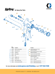
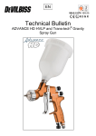
Operating manual
for
automaticspray valve ASV
Read this manual carefully before installing, operating or servicing this equipment.
Keep always handy for further use.
ALFRED SCHÜTZE Apparatebau GmbH
- Spritztechnik – Spraytechnology Hannoversche Straße 69-71, 28309 Bremen – Germany;
Postfach 44 86 48, 28286 Bremen - Germany
Tel.: 0049 (0)421 / 43510-0; Fax: 0049 (0)421 / 43510-43
Internet: http://www.schuetze-gmbh.de
E-Mail: [email protected]
1 Introduction
The automatic spray valve ASV is designed and constructed for application of thin materials f.i. release
agents, oils, colours and in version KLS also for glues and adhesives. Depending on position of
continuously adjustable regulation of sprayjet, this spray valve sprays from round- to 90° flatspray.
Depending on viscosity of fluid, the application can be adjusted individually via nozzle dimension,
atomizing air pressure, material pressure and the continuously adjustable sprayjet regulation. The
supply of atomizing air, control air and material should be done via three hoses (with remote-controlled
regulation of sprayjet = four hoses). Spray valves are precision tools. Always keep clean and observe
minimum instructions to maintain a long useful life of the valve.
2 Safety
2.1 Duties of the user
•
•
The user must read this service manual carefully before performing any operations.
Application and service operations should not be carried out if the user is not absolutely sure of
the purpose and consequence of the operations.
2.2 Definitive Use
The automatic spray valve ASV is a pneumatically controlled needle valve. It is suitable for continuously
or intermittent use. They are not suitable for spraying aggressive fluids like acid, alkaline solutions,
cleaning agents, chemicals etc.. In case of doubt, please contact the manufacturer.
2.3 Warning against danger
This operating manual warns users of operations which may put their health at risk. The warnings are
indicated by combinations of text and symbols corresponding to the different danger classes.
WARNING!
Signs a possible dangerous situation.
If you don´t avoid, death or severe injuries can follow.
CAUTION!
Indicates a situation which may be dangerous.
Failure to heed the caution may result in personal injury. This indication is also used where material
damage is possible.
IMPORTANT!
Indicates tips for usage and other helpful information.
3 Function Description
The automatic spray valve ASV is pneumatically controlled: air open; spring return.
The spraying material is to be fed to the valve via pressure tank or pump. The separate controlled
atomizing air atomizes the material to a spray jet. Depending on position of continuously adjustable
sprayjet regulation, the valve sprays from a round- up to a 90° flatspray.
4 Installation
The automatic spray valve ASV can be installed in any position. For solid attachment the use of clamp
(option, drawing no.: 15.0) is recommend. Vibration of the equipped machine to the valve should be
limited as far as possible. Vibrations of the valve caused by fast intermitting cycles require solid and
massive installation.
4.1 Hose connection and assembly
Connect hoses for atomizing air and control air to seperatly control valves (pressure reducers and
solenoids). Then fluidhose to material pressure tank or other means of feeding fluid as under:
•
atomizing air, marked with “Z” (draw.-no.: 6.0, hose blue):
Î
to 2/2 way solenoid
•
control air,
marked with “S” (draw.-no.: 6.0, hose black):
Î
to 3/2 way solenoid
•
fluid,
marked with “M” (draw.-no.: 6.0, hose transparent):
Î
to feeding device
OPTIONAL:
•
•
remote-controlled regulation of sprayjet,
Î
to 2/2 way solenoid
material circulation,
Î
back to feeding device
(draw.-no.: 16.0, hose blue):
(draw.-no.: 6.0, hose black):
4.2 Spray pattern regulation
Turn the spray pattern regulator (7.0) to adjust the spray pattern. Turn anti-clockwise for a wider jet
spray and clockwise for a rounder spray. The adjustment is continuous, not in steps.
Optionally the spray pattern regulation can be done pneumatically controlled. For this option turn spray
pattern regulator (7.0) clockwise completely.
Now the regulation of atomizing air for the cone holes can be done via additional air connection M5
(16.0) via pressure regulator remote-controlled.
4.3 Operating instructions
CAUTION !
Never point the sprayjet against persons. Wearing eye protection is strongly
recommended. Spraying procedures cause noises depending on the used pressure.
If necessary, wearing of ear protection is recommend.
WARNING !
Danger caused by combustible and noxious spraying material. Safety instructions on
fluid can and material data of fluid manufacturer must definitely be observed.
The automatic spray valve ASV needs 3,5 – 6 bar control air pressure. Atomizing air pressure and
material pressure should be as low as possible. In any case, please observe the regulations of the
professional/trade association having liability for industrial safety and insurance.
When you are certain, that fluid pressure stands up to the nozzle, actuate 2/2 way solenoid for
atomizing air. After that actuate 3/2 way solenoid for control air. This way you reveive socalled “pre-air”
prior to opening fluid flow. After each cycle solenoids are to actuate in reverse order, so you will still
have “purging-air” after needle has closed nozzle and fluid flow was stopped. This prevent fluid to form
out drops instead of being atomized.
Set atomizing air pressure and fluid pressure according to required spray droplet sizes. Two separate
pressure reducers must be available. Intermittend use as well as continuous use is possible. Maximal
40 cycles per second are possible (under optimal working conditions).
IMPORTANT !
The quantity of fluid flow can be adjusted by the regulating knob (draw.-no.: 13.0).
Turning this knob in anti-clockwise turn
= more fluid flow
Turning this knob in clockwise turn
= less fluid flow
Do not over-tight the regulating knob.
IMPORTANT !
To avoid damages to nozzle and needle adjust decrease of fluid flow (turning
regulating knob 16.0 clockwise) only when fluid is emitted from the nozzle. This is the
only way to observe the steady reduction of fluid flow until an absolute stop of fluid.
Going on to turn the regulating knob clockwise would at once push the needle into the
nozzle to such an extant that both parts could be damages.
It is harmless to leave fluid within the valve (no connection to outside air), if system stays under
pressure.
5 Repair and Maintance
Before starting maintenance or repair work, ensure that all air operated tools are disconnected from the
air supply.
WARNING !
Danger caused by combustible and noxious spraying material. Safety instructions on
fluid can and material data of fluid manufacturer must definitly be observed.
WARNING !
Before opening the spray valve it has to be disconnected from the air and fluid
supply. Otherwise ejected elements can cause danger.
The automatic spray valve ASV is a high precision tool. Always keep clean and observe minimum
instructions to maintain a long and useful life of valve. We recommend lubricating moveable parts
regularly, and greasing threads, especially the nozzle threads, when replacing or cleaning the nozzle. It
is recommended to use clean and filtered application fluid only. Also atomizing air should be clean.
Control air should be slightly oiled.
5.1 Cleaning
To clean valve, spray solvent until pure solvent leaves nozzle. Do not submerge entire valve in solvent.
At longer working interruptions it is advisable to clean air cap and nozzle by putting these parts only into
solvent. If necessary use a soft brush. Moving parts and threads should alway be greased slightly.
The spray valve should be cleaned using an appropiate thinner. To clean small drill holes, use our
special nozzle cleaning needles.
These spray valves are high precision tools. Always keep clean and observe minimum instructions to
maintain a long and useful life of valve.
We recommend lubricating moveable parts regularly, and greasing threads, especially the nozzle
threads, when replacing or cleaning the nozzle.
5.2 Possible case of failure: Needle sticks
•
•
•
•
Check, if sufficient control / operating air is supplied (3,5 - 6 bar).
Check, if o-ring (9.1) is in propper order.
Check, if needle is dirted by f.i. glue residues or sticks within needle gasket (8.1 / 8.4) or within
nozzle.
Check, if minimum of travel of needle is set.
Troube shooting.
•
•
If drops form on the nozzle, either needle or nozzle is worn out and should be replaced. Or
needle is not closing properly f.i. because particle residues within nozzle.
If there is an uneven or not steady spray jet, make sure that nozzle is screwed in tight. Other
reason could also be dirt residue within air cap.
5.3 Changing the nozzle set
IMPORTANT!
Nozzles, gaskets and gasket seats can be damaged. Do not use metallical aid to
remove and insert those parts.
A nozzle set includes needle (9.0), nozzle (3.0) and air cap (2.0).
If nozzle size is to be changed, always change all these three parts. Change the complete set also
when only one of the parts is defect.
Disconnect all air operated tools from the air supply.
•
Take off closing plate (14.0) by unscrewing screws (12.0).
•
Pull out needle spring (10.0) and needle (9.0).
•
Take off air cap (2.0) after unscrewing collar ring (1.0).
•
Screw out nozzle (3.0) with wrench, size SW 6. Before unscrewing nozzle, please
observe that needle is never under spring pressure.
Reassemble in reverse order.
To prevent damage to the needle seat during replacement, the needle (9.0) must only be inserted into
firmly installed nozzle.
5.4 Changing needle gasket
IMPORTANT!
Gaskets and gasket seats can be damaged. Do not use metallical aid to
remove and insert those parts.
approx.50 mm
Before starting maintenance or repair work, ensure that all air operated tools are disconnected from the
air supply.
Take of closing plate (14.0) by unscrewing screws (12.0). Pull out needle spring (10.0) and needle
(9.0). Then unscrew retainer (8.0).
After unscrewing retainer (8.0) all o-rings and gaskets (8.1 / 8.2 / 8.4 / 8.5) can be changed. The o-ring
(9.1) can be changed from the needle piston.
Reassemble in reverse order.
Square 30x30
ø20
10
Clamp (OPTION)
40.5
approx.72.5 mm
approx.45 mm
Connection for fluid circulation (OPTION)
6.0
16.0
17.0
1.0
2.0
15.0
3.0
4.0
15.2
15.1
18.0 8.1
5.0
8.2
8.3
6.0
8.4
7.1
8.5
7.2
8.0
7.0
9.0
9.1
14.0
14.4
12.0
11.0
14.3
14.2
14.1
10.0
13.1
13.2
14.1
14.2
14.3
13.0
6. Spareparts list
draw.-no.:
1.0
2.0
2.1
3.0
4.0
5.0
6.0
7.0
7.1
7.2
8.0
8.1
8.2
8.3
8.4
8.5
9.0
9.1
10.0
11.0
12.0
13.0
13.1
13.2
14.0
14.1
14.2
14.3
14.4
15.0
15.1
15.2
16.0
17.0
18.0
part-number:
410028
*
*
*
510345
220300
*
380032
380033
640003
810054
640155
640317
810053
640026
640316
*
640007
820076
320318
610055
320668
320609
610034
511021
610017
820077
650004
510346
910015
910014
610042
220089
610063
610249
Quantity
1
1
1
1
1
1
3/4
1
1
1
1
1
1
1
1
2
1
1
1
1
2
1
1
1
1
2
2
2
1
1
1
2
1
1
1
Description
collar ring, ø 23 x 10mm
aircap, flatspray, ø 20 x 14,5mm
aircap, roundspray, ø 20 x 11mm
nozzle, stainless steel, ø 12 x 18mm
valve body ASV, stainless steel, complete
screw, stainless steel, 1/8"
screw for material and air
regulating screw (round-/flatspray regulation), complete
regulating screw, M6x0,5 x 11mm
o-ring 4 x 1 / Viton
retainer, complete
shaped gasket 3,0 x 2,15 x 1,35
o-ring 7 x 1,5 / Viton
retainer, ø 14,94 x 19,5mm
o-ring 2,9 x 1,78 / Viton
o-ring 13 x 1 / Viton
needle, complete
o-ring 14 x 1,78 / Viton
spring 0,9 x 24mm
ratchet screw, ø 13 x 18,5mm
screw DIN 7991 M4 x 10
regulating knob, stainless steel, complete
regulating knob, ø 20 x 9mm, stainless steel
pin DIN 915 M4 x 6
closing plate, complete
pin DIN 913 M3 x 3
spring 0,4 x 5,5mm
ball, stainless steel, ø 2,5mm
closing plate, stainless steel, 30 x 30 x 10,5mm
clamp, complete (OPTION)
clamp, 21,5 x 25 x 15mm
screw DIN 6912 M5 x 14
screw M5, SW8 x 19mm, complete (OPTION)
screw M5, complete with seal
pin DIN 915 M3 x 3
* Please find part-numbers on page 8.
When ordering nozzle sets, please specify dimension.
Available dimensions: 0,2 / 0,3 / 0,5 / 0,8 / 1,0 / 1,2 / 1,5 / 2,0 / 2,5 mm ∅
nozzle set = needle, nozzle and aircap.
If nozzle size is to be changed, always change all these three parts. Change the complete set also
when only one of the parts is defect.
6.1 part-numbers for needles, nozzles and aircaps
*needles
draw.-no.
9.0
9.0
9.0
9.0
9.0
9.0
9.0
9.0
part.-no.
110884
110885
110886
110887
110888
110889
110890
110891
*nozzles
description
0,2/0,3mm
0,5mm
0,8mm
1,0mm
1,2mm
1,5mm
2,0mm
2,5mm
draw.-no.
3.0
3.0
3.0
3.0
3.0
3.0
3.0
3.0
3.0
part-no.
210110
210111
210112
210113
210114
210115
210116
210117
210118
* aircap / flatspray 90° (standard version)
draw.-no.
2.0
2.0
2.0
2.0
part.-no.
310238
310239
310240
310241
description
for nozzle 0,2-1,0mm
for nozzle 1,2-1,5mm
for nozzle 1,8-2,0mm
for nozzle 2,5mm
* aircap / flatspray 60°
draw.-no.
2.0
2.0
2.0
2.0
part.-no.
310234
310235
310236
310237
description
for nozzle 0,2-1,0mm
for nozzle 1,2-1,5mm
for nozzle 1,8-2,0mm
for nozzle 2,5mm
* aircap / roundspray 15°
draw.-no.
2.1
2.1
2.1
2.1
part-no.
310034
310035
310080
310091
description
for nozzle 0,2-1,0mm
for nozzle 1,2-1,5mm
for nozzle 1,8-2,0mm
for nozzle 2,5mm
* screw for material and air
draw.-no. part-no.
6.0
220022
6.0
220243
description
screw with nut SW 13x28mm / 1/8" - 6/4 (standard)
screw with nut SW 13x28mm / 1/8" - 8/6
description
0,2mm
0,3mm
0,5mm
0,8mm
1,0mm
1,2mm
1,5mm
2,0mm
2,5mm
7. Technical data
measurements
= approx. 50mm x 45mm x 72,5mm lenght
weight
= approx. 305 g
air consumption (standard version) = approx. 111 ltr. per minute (3 bar; 0,3 mm nozzle;
flatspray aircap; 2m hose length)
air consumption (remote-controlled) = approx. 133 ltr. per minute (3 bar; 0,3 mm nozzle;
Flatspray aircap; 2m hose length)
control air pressure
= minimum: 3,5 bar , maximum 6 bar
atomizing air pressure
= as required
material pressure
= max. 10 bar
Special designs on request. Technical alterations reserved. May 2009.
8. Manufacturer declaration
The automatic spray valve ASV is constructed and produced by
ALFRED SCHÜTZE Apparatebau GmbH, Hannoversche Straße 69-71, 28309 Bremen – Germany
in accordance with the guidelines and standards of DIN EN 292. This spray valve can be combined with
other modules or machines, which comply to DIN EN 292, without limiting the conformity.
Place
Bremen
Date
29.05.2009
Signature of manufacturer